EP4034966B1 - Display devices of computing devices - Google Patents
Display devices of computing devices Download PDFInfo
- Publication number
- EP4034966B1 EP4034966B1 EP19947353.9A EP19947353A EP4034966B1 EP 4034966 B1 EP4034966 B1 EP 4034966B1 EP 19947353 A EP19947353 A EP 19947353A EP 4034966 B1 EP4034966 B1 EP 4034966B1
- Authority
- EP
- European Patent Office
- Prior art keywords
- housing
- display device
- computing device
- magnetic track
- magnetic
- Prior art date
- Legal status (The legal status is an assumption and is not a legal conclusion. Google has not performed a legal analysis and makes no representation as to the accuracy of the status listed.)
- Active
Links
Images



Classifications
-
- G—PHYSICS
- G06—COMPUTING OR CALCULATING; COUNTING
- G06F—ELECTRIC DIGITAL DATA PROCESSING
- G06F1/00—Details not covered by groups G06F3/00 - G06F13/00 and G06F21/00
- G06F1/16—Constructional details or arrangements
- G06F1/1613—Constructional details or arrangements for portable computers
- G06F1/1615—Constructional details or arrangements for portable computers with several enclosures having relative motions, each enclosure supporting at least one I/O or computing function
- G06F1/1616—Constructional details or arrangements for portable computers with several enclosures having relative motions, each enclosure supporting at least one I/O or computing function with folding flat displays, e.g. laptop computers or notebooks having a clamshell configuration, with body parts pivoting to an open position around an axis parallel to the plane they define in closed position
-
- G—PHYSICS
- G06—COMPUTING OR CALCULATING; COUNTING
- G06F—ELECTRIC DIGITAL DATA PROCESSING
- G06F1/00—Details not covered by groups G06F3/00 - G06F13/00 and G06F21/00
- G06F1/16—Constructional details or arrangements
- G06F1/1613—Constructional details or arrangements for portable computers
- G06F1/1615—Constructional details or arrangements for portable computers with several enclosures having relative motions, each enclosure supporting at least one I/O or computing function
- G06F1/1624—Constructional details or arrangements for portable computers with several enclosures having relative motions, each enclosure supporting at least one I/O or computing function with sliding enclosures, e.g. sliding keyboard or display
-
- G—PHYSICS
- G06—COMPUTING OR CALCULATING; COUNTING
- G06F—ELECTRIC DIGITAL DATA PROCESSING
- G06F1/00—Details not covered by groups G06F3/00 - G06F13/00 and G06F21/00
- G06F1/16—Constructional details or arrangements
- G06F1/1613—Constructional details or arrangements for portable computers
- G06F1/1633—Constructional details or arrangements of portable computers not specific to the type of enclosures covered by groups G06F1/1615 - G06F1/1626
- G06F1/1637—Details related to the display arrangement, including those related to the mounting of the display in the housing
-
- G—PHYSICS
- G06—COMPUTING OR CALCULATING; COUNTING
- G06F—ELECTRIC DIGITAL DATA PROCESSING
- G06F1/00—Details not covered by groups G06F3/00 - G06F13/00 and G06F21/00
- G06F1/16—Constructional details or arrangements
- G06F1/1613—Constructional details or arrangements for portable computers
- G06F1/1633—Constructional details or arrangements of portable computers not specific to the type of enclosures covered by groups G06F1/1615 - G06F1/1626
- G06F1/1637—Details related to the display arrangement, including those related to the mounting of the display in the housing
- G06F1/1647—Details related to the display arrangement, including those related to the mounting of the display in the housing including at least an additional display
-
- G—PHYSICS
- G06—COMPUTING OR CALCULATING; COUNTING
- G06F—ELECTRIC DIGITAL DATA PROCESSING
- G06F1/00—Details not covered by groups G06F3/00 - G06F13/00 and G06F21/00
- G06F1/16—Constructional details or arrangements
- G06F1/1613—Constructional details or arrangements for portable computers
- G06F1/1633—Constructional details or arrangements of portable computers not specific to the type of enclosures covered by groups G06F1/1615 - G06F1/1626
- G06F1/1675—Miscellaneous details related to the relative movement between the different enclosures or enclosure parts
- G06F1/1681—Details related solely to hinges
Definitions
- notebook computers, or laptops are one of the more widely used devices and generally employ a clamshell-type design consisting of two housings connected together at a common end via hinges, for example.
- a first housing includes a display device to provide a viewable display to a user
- a second housing or base member includes an area for user input (e.g., touchpad and keyboard).
- the viewable display may be a touchscreen (e.g., touchscreen laptop), allowing the user to interact directly with what is displayed by touching the screen with simple or multi-touch gestures.
- TW M 579 314 U describes an electronic device comprising first, second and third bodies, wherein the second body is pivotally arranged on the first body, and the third body is located between the first body and the second body and can be partially removed from the second body.
- US 2011/023272 A1 describes a hinge mechanism and an electronic device therewith.
- the second display device 110 may synchronously move with the rotation of the first housing 104.
- a first end 116 of the second display device 110 may slide along a surface of the second housing 108 and a second end 114 of the second display device 110 may slide along a surface of the first housing 104.
- the synchronized movement of the second display device 110 may allow for the second end 114 of the second display device 110 to cover at least a substantial portion of the bottom bezel on the first housing 104 as the first housing 104 is rotated, thereby providing a seamless look between the first display device 106 and second display device 110, as illustrated.
- a magnetic track 120 is disposed in the second housing 108, to provide an attracting force to hold the first end 116 of the second display device 110 in contact with the surface of the second housing 108.
- a magnetic member 122 may be included in the second housing 110 to be magnetically attached along the magnetic track 120.
- a magnetic track 124 may be disposed in the first housing 104, to provide an attracting force to hold a portion of the second display device 110 in contact with the surface of the first housing 104, for example, the second end 114 of the second display device 110.
- a magnetic member 126 may be included in the second housing 110 to be magnetically attached along the magnetic track 124.
- FIGs. 2A-D illustrate synchronized movement of the second display device 110 of computing device 100 as the first housing 104 is rotated open, according to an example.
- the computing device 100 is closed, where the first housing 104 is closed onto the second housing 108.
- the second display device 110 is disposed within a cavity of the second housing 108.
- Magnetic member 122 is magnetically attached to magnetic track 120 and magnetic member 124 is magnetically attached to magnetic track 124.
- FIG. 2B as the first housing 104 is rotated open, magnetic member 122 remains magnetically attached to magnetic track 120 and magnetic member 124 remains magnetically attached to magnetic track 124.
- magnetic member 126 correspondingly moves along magnetic track 124.
- the movement of the second display device 110 may be synchronized with the rotation of the first housing 104.
- the viewing angle of the second display device 110 may be raised from the flat position illustrated in FIG. 2A , which may be desirable for a user while utilizing the computing device 100.
- the raised viewing angle of the second display device 110 may reduce neck fatigue and discomfort for the user.
- magnetic member 122 continues to move further along magnetic track 120, for example, to the end of the magnetic track 120, and magnetic member 126 correspondingly moves along magnetic track 124 as well. Similar to how the computing device 100 is opened, the second display device 110 may return into the cavity of the second housing 108 when the first housing 104 is rotated back closed.
- the second display device 110 may cover at least a substantial portion of the bottom bezel on the first housing 104 as the first housing 104 is rotated, for example, via the magnetic tracks 120, 124 and their associated magnets 122, 126.
- a seamless look may be provided between the first display device 106 and second display device 110, essentially reducing the gap between the second display device 110 and first display device 106, which may be desirable to a user.
- the elevation of the portion of the "C" deck including the secondary display device 110 creates a gap underneath as illustrated, for example, to allow for additional thermal venting. As a result, more air may flow through the computing device 100, through the opening or gap created when the portion of the "C" deck including the secondary display device 110 is lifted.
- the connector 112 may include a spring mechanism 302 to bias the connector 112 towards the first housing 104 and, as a result, to cause the second end 114 of the second display device 110 to slide along a surface of the first housing 104 while the first housing 104 is rotated relative to the second housing 108.
- the arrangement of the spring mechanism 302 may vary, and is not limited to the arrangement illustrated.
- FIGs. 4A-B illustrate synchronized movement of the second display device 110 of computing device 300 as the first housing 104 is rotated open, according to an example.
- the computing device 300 is closed, where the first housing 104 is closed onto the second housing 108.
- the second display device 110 is disposed within a cavity of the second housing 108.
- Magnetic member 122 is magnetically attached to magnetic track 120.
- spring mechanism 302 may be held under tension while the computing device 300 is closed, in order to bias the connector 112 towards the first housing 104 as it is rotated (e.g., see FIG. 4B ).
- spring mechanism 302 may bias the connector 112 towards the first housing 104 and, as a result, cause the second end 114 of the second display device 110 to slide along a surface of the first housing 104.
- magnetic member 122 moves further along magnetic track 120, compared to the position illustrated in FIG. 4A .
- the spring mechanism 302 may continue to be held under tension while the first housing 104 is rotated open, in order for the connector 112 to remain biased towards the first housing 104.
- the second display device 110 may return into the cavity of the second housing 108 when the first housing 104 is rotated back closed.
- spring mechanisms or magnetic members, or a combination of them were described in order to provide synchronized movement of a second display device in response to rotation of a first housing relative to the second housing, other mechanisms may be relied upon as well.
- gear mechanisms may be relied on to provide for the synchronized movement.
- examples described may include various components and features. It is also appreciated that numerous specific details are set forth to provide a thorough understanding of the examples. However, it is appreciated that the examples may be practiced without limitations to these specific details. In other instances, well known methods and structures may not be described in detail to avoid unnecessarily obscuring the description of the examples. Also, the examples may be used in combination with each other.
Landscapes
- Engineering & Computer Science (AREA)
- Theoretical Computer Science (AREA)
- Computer Hardware Design (AREA)
- Physics & Mathematics (AREA)
- Human Computer Interaction (AREA)
- General Engineering & Computer Science (AREA)
- General Physics & Mathematics (AREA)
- Mathematical Physics (AREA)
- Devices For Indicating Variable Information By Combining Individual Elements (AREA)
Description
- The emergence and popularity of mobile computing has made portable computing devices, due to their compact design and light weight, a staple in today's marketplace. Within the mobile computing realm, notebook computers, or laptops, are one of the more widely used devices and generally employ a clamshell-type design consisting of two housings connected together at a common end via hinges, for example. In most cases, a first housing includes a display device to provide a viewable display to a user, while a second housing or base member includes an area for user input (e.g., touchpad and keyboard). In addition, the viewable display may be a touchscreen (e.g., touchscreen laptop), allowing the user to interact directly with what is displayed by touching the screen with simple or multi-touch gestures.
TW M 579 314 U US 2011/023272 A1 describes a hinge mechanism and an electronic device therewith. - The scope of the invention is defined by the appended claims.
-
-
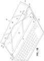
FIGs. 1A-B illustrate a computing device including a first display device and a second display device, according to an example; -
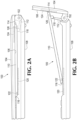
FIGs. 2A-D illustrate synchronized movement of the second display device of computing device as the first housing is rotated open, according to an example; -
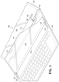
FIG. 3 illustrates a mechanism for allowing synchronized movement of a second display device in response to rotation of a first housing relative to a second housing, according to an example; and -
FIGs. 4A-B illustrate synchronized movement of the second display device of computing device as the first housing is rotated open, according to an example. - Examples disclosed herein provide an additional display device for computing devices, such as the notebook computer described above. As an example, the additional display device, or secondary display device may be disposed in a second housing of the computing device, separate from the primary display device disposed in the first housing of the computing device. As an example, the secondary display device may be included on a "C" deck of a notebook computer (e.g., a topside of the base member). As will be further described, the portion of the "C" deck including the secondary display device may be elevated as the first housing is rotated with respect to the second housing, thereby providing an appropriate viewing angle of the secondary display device. In addition, movement or elevation of the secondary display device may be synchronized with the opening and closing of the computing device, such that the primary and secondary display devices may provide a seamless look. In addition to providing a desirable viewing angle as the computing device is opened, the elevation of the portion of the "C" deck including the secondary display device creates a gap underneath to allow for additional thermal venting, to allow for more efficient cooling. As a result, more air may flow through the computing device, through the opening or gap created when the portion of the "C" deck including the secondary display device is lifted.
- With reference to the figures,
FIG. 1A illustrates acomputing device 100 including afirst display device 106 and asecond display device 110, according to an example. As illustrated, thefirst display device 106 is disposed in afirst housing 104 of the computing device, and thesecond display device 110 is disposed in asecond housing 108 that is rotatably coupled to thefirst housing 104 via ahinge 102. As illustrated, thesecond display device 110 may be included on a "C" deck of thecomputing device 100, or a topside of the second housing 108 (e.g., base member of a notebook computer). - As will be further described, as the
first housing 104 is rotated opened or closed, thesecond display device 110 may synchronously move with the rotation of thefirst housing 104. For example, in response to a rotation of thefirst housing 104 relative to thesecond housing 108, afirst end 116 of thesecond display device 110 may slide along a surface of thesecond housing 108 and asecond end 114 of thesecond display device 110 may slide along a surface of thefirst housing 104. As a result, the synchronized movement of thesecond display device 110 may allow for thesecond end 114 of thesecond display device 110 to cover at least a substantial portion of the bottom bezel on thefirst housing 104 as thefirst housing 104 is rotated, thereby providing a seamless look between thefirst display device 106 andsecond display device 110, as illustrated. - Referring to
FIG. 1B , portions of thecomputing device 100 are illustrated in phantom, in order to provide details on the mechanism for allowing synchronized movement of thesecond display device 110 in response to rotation of thefirst housing 104 relative to thesecond housing 108, according to an example. Aconnector 112 is coupled to thehinge 102 and thesecond display device 110. As illustrated, theconnector 112 is pivotally attached to thesecond display device 110, for example, at 118. As will be further described, magnetic members may allow for the synchronized movement of thesecond display device 110 in response to rotation of thefirst housing 104 relative to thesecond housing 108. - Referring to
FIG. 1B , amagnetic track 120 is disposed in thesecond housing 108, to provide an attracting force to hold thefirst end 116 of thesecond display device 110 in contact with the surface of thesecond housing 108. As an example, amagnetic member 122 may be included in thesecond housing 110 to be magnetically attached along themagnetic track 120. Similarly, amagnetic track 124 may be disposed in thefirst housing 104, to provide an attracting force to hold a portion of thesecond display device 110 in contact with the surface of thefirst housing 104, for example, thesecond end 114 of thesecond display device 110. As an example, amagnetic member 126 may be included in thesecond housing 110 to be magnetically attached along themagnetic track 124. The arrangement of the magnetic tracks and associated magnetic members may vary, and are not limited to the arrangement illustrated. As a result ofmagnetic tracks magnets second display device 110 may be possible in response to rotation of thefirst housing 104 relative to thesecond housing 108, as will be illustrated inFIGs. 2A-D . -
FIGs. 2A-D illustrate synchronized movement of thesecond display device 110 ofcomputing device 100 as thefirst housing 104 is rotated open, according to an example. Referring toFIG. 2A , thecomputing device 100 is closed, where thefirst housing 104 is closed onto thesecond housing 108. In this position, thesecond display device 110 is disposed within a cavity of thesecond housing 108.Magnetic member 122 is magnetically attached tomagnetic track 120 andmagnetic member 124 is magnetically attached tomagnetic track 124. Referring toFIG. 2B , as thefirst housing 104 is rotated open,magnetic member 122 remains magnetically attached tomagnetic track 120 andmagnetic member 124 remains magnetically attached tomagnetic track 124. However, asmagnetic member 122 moves further alongmagnetic track 120, compared to the position illustrated inFIG. 2A ,magnetic member 126 correspondingly moves alongmagnetic track 124. As a result, the movement of thesecond display device 110 may be synchronized with the rotation of thefirst housing 104. - Referring to
FIG. 2B , bymagnetic member 126 moving further up themagnetic track 124 as thefirst housing 104 is rotated open, the viewing angle of thesecond display device 110 may be raised from the flat position illustrated inFIG. 2A , which may be desirable for a user while utilizing thecomputing device 100. The raised viewing angle of thesecond display device 110 may reduce neck fatigue and discomfort for the user. Referring toFIG. 2C , as thefirst housing 104 continues to be opened,magnetic member 122 continues to move further alongmagnetic track 120, for example, to the end of themagnetic track 120, andmagnetic member 126 correspondingly moves alongmagnetic track 124 as well. Similar to how thecomputing device 100 is opened, thesecond display device 110 may return into the cavity of thesecond housing 108 when thefirst housing 104 is rotated back closed. - In addition to providing a desirable viewing angle, the
second display device 110 may cover at least a substantial portion of the bottom bezel on thefirst housing 104 as thefirst housing 104 is rotated, for example, via themagnetic tracks magnets first display device 106 andsecond display device 110, essentially reducing the gap between thesecond display device 110 andfirst display device 106, which may be desirable to a user. - In addition to providing a desirable viewing angle as the
computing device 100 is opened, the elevation of the portion of the "C" deck including thesecondary display device 110 creates a gap underneath as illustrated, for example, to allow for additional thermal venting. As a result, more air may flow through thecomputing device 100, through the opening or gap created when the portion of the "C" deck including thesecondary display device 110 is lifted. - In addition to the gap created underneath the
second display device 110, area in the cavity of thesecond housing 108, by thefirst end 116 of thesecond display device 110, becomes available for use as well. As an example, a component may be disposed in the cavity of thesecond housing 108, available for use whensecond display device 110 is elevated out of the cavity. Examples of such components include, but are not limited to, an input device, an output device, or a structure associated with thermal management ofcomputing device 100. For example, the components may be a set of keys for input, a set of vents for thermal management, or an audio component, such as a set of speakers for output - Referring to
FIG. 2D , in addition to followingmagnetic track 120, if an opposing force is applied to overcome the magnetic attraction betweenmagnetic track 120 andmagnetic member 122, the angle of thesecond display device 110 may be adjusted by lifting up the second display device from itsfirst end 116, as illustrated. Similarly, an opposing force may be applied to overcome the magnetic attraction betweenmagnetic track 124 andmagnetic member 126, in order to separate thesecond display device 110 from thefirst housing 104 at itssecond end 116. -
FIG. 3 illustrates portions of acomputing device 300 in phantom, in order to provide details on the mechanism for allowing synchronized movement of thesecond display device 110 in response to rotation of thefirst housing 104 relative to thesecond housing 108, according to an example. Elements of thecomputing device 300 may be similar tocomputing device 100 and, as a result, may share the reference numbers for such elements. As an example, aconnector 112 may be coupled to thehinge 102 and thesecond display device 110. As illustrated, theconnector 112 may be pivotally attached to thesecond display device 110, for example, at 118. - As an example, in order to allow for the synchronized movement of the
second display device 110 in response to rotation of thefirst housing 104 relative to thesecond housing 108, theconnector 112 may include aspring mechanism 302 to bias theconnector 112 towards thefirst housing 104 and, as a result, to cause thesecond end 114 of thesecond display device 110 to slide along a surface of thefirst housing 104 while thefirst housing 104 is rotated relative to thesecond housing 108. The arrangement of thespring mechanism 302 may vary, and is not limited to the arrangement illustrated. - In addition to the
spring mechanism 302, in order to allow for the synchronized movement of thesecond display device 110, amagnetic track 120 may be disposed in thesecond housing 108, to provide an attracting force to hold a portion of thesecond display device 110 in contact with the surface of thesecond housing 108, for example, thefirst end 116 of thesecond display device 110. As an example, amagnetic member 122 may be included in thesecond housing 110 to be magnetically attached along themagnetic track 120. As a result of the combined effort from thespring mechanism 302 and the magnetic members (i.e.,magnetic track 120 and associated magnetic member 122), synchronized movement of thesecond display device 110 may be possible in response to rotation of thefirst housing 104 relative to thesecond housing 108, as will be illustrated inFIGs. 4A-B . -
FIGs. 4A-B illustrate synchronized movement of thesecond display device 110 ofcomputing device 300 as thefirst housing 104 is rotated open, according to an example. Referring toFIG. 4A , thecomputing device 300 is closed, where thefirst housing 104 is closed onto thesecond housing 108. In this position, thesecond display device 110 is disposed within a cavity of thesecond housing 108.Magnetic member 122 is magnetically attached tomagnetic track 120. In addition,spring mechanism 302 may be held under tension while thecomputing device 300 is closed, in order to bias theconnector 112 towards thefirst housing 104 as it is rotated (e.g., seeFIG. 4B ). - Referring to
FIG. 4B , as thefirst housing 104 is rotated open,spring mechanism 302 may bias theconnector 112 towards thefirst housing 104 and, as a result, cause thesecond end 114 of thesecond display device 110 to slide along a surface of thefirst housing 104. in addition, by relying on thespring mechanism 302 to bias theconnector 112 towards thefirst housing 104,magnetic member 122 moves further alongmagnetic track 120, compared to the position illustrated inFIG. 4A . As an example, thespring mechanism 302 may continue to be held under tension while thefirst housing 104 is rotated open, in order for theconnector 112 to remain biased towards thefirst housing 104. Similar to how thecomputing device 300 is opened, thesecond display device 110 may return into the cavity of thesecond housing 108 when thefirst housing 104 is rotated back closed. - Although spring mechanisms or magnetic members, or a combination of them were described in order to provide synchronized movement of a second display device in response to rotation of a first housing relative to the second housing, other mechanisms may be relied upon as well. For example, gear mechanisms may be relied on to provide for the synchronized movement.
- It is appreciated that examples described may include various components and features. It is also appreciated that numerous specific details are set forth to provide a thorough understanding of the examples. However, it is appreciated that the examples may be practiced without limitations to these specific details. In other instances, well known methods and structures may not be described in detail to avoid unnecessarily obscuring the description of the examples. Also, the examples may be used in combination with each other.
- Reference in the specification to "an example" or similar language means that a particular feature, structure, or characteristic described in connection with the example is included in at least one example, but not necessarily in other examples. The various instances of the phrase "in one example" or similar phrases in various places in the specification are not necessarily all referring to the same example.
- It is appreciated that the previous description of the disclosed examples is provided to enable any person skilled in the art to make or use the present disclosure. Various modifications to these examples will be readily apparent to those skilled in the art, and the generic principles defined herein may be applied to other examples without departing from the scope of the disclosure. Thus, the present disclosure is not intended to be limited to the examples shown herein but is to be accorded the widest scope consistent with the principles and novel features disclosed herein.
Claims (8)
- A computing device (100) comprising:a hinge (102);a first housing (104) comprising a first display device (106);a second housing (108) rotatably coupled to the first housing via the hinge, the second housing comprising a magnetic track (120);a second display device (110) disposed in the second housing;a connector (112) coupled to the hinge and the second display device, wherein the connector is pivotally attached to the second display device;wherein, in response to a rotation of the first housing relative to the second housing:a first end (116) of the second display device is to remain magnetically attached to the second housing via the magnetic track of the second housing; andeither:a second end (114) of the second display device is to remain magnetically attached to the first housing via a magnetic track (124) of the first housing; ora spring mechanism (302) of the connector is to cause the second end of the second display device to slide along a surface of the first housing, wherein the spring mechanism is to bias the connector toward the first housing.
- The computing device of claim 1 wherein, in response to the rotation of the first housing relative to the second housing, the second end of the second display device is to remain magnetically attached to the first housing via the magnetic track of the first housing.
- The computing device of claim 2, wherein the first end of the second display device comprises a first magnetic member (122) to remain magnetically attached to the magnetic track of the second housing, and the second end of the second display device comprises a second magnetic member (126) to remain magnetically attached to the magnetic track of the first housing.
- The computing device of claim 3, wherein the first magnetic member to remain magnetically attached to the magnetic track of the second housing comprises the first end of the second display device to slide along a surface of the second housing.
- The computing device of claim 4, wherein the second magnetic member to remain magnetically attached to the magnetic track of the first housing comprises the second end of the second display device to slide along a surface of the first housing.
- A computing device as claimed in claim 1 wherein:
the connector comprises the spring mechanism to bias the connector toward the first housing, wherein, in response to the rotation of the first housing relative to the second housing, the spring mechanism is to cause the first end of the second display device to slide along a surface of the first housing. - The computing device of claim 6, wherein the spring mechanism is held under tension in order to bias the connector toward the first housing.
- The computing device of claim 6, wherein the second end of the second display device comprises a magnetic member (122) to remain magnetically attached to the magnetic track of the second housing.
Applications Claiming Priority (1)
| Application Number | Priority Date | Filing Date | Title |
|---|---|---|---|
| PCT/US2019/053414 WO2021061148A1 (en) | 2019-09-27 | 2019-09-27 | Display devices of computing devices |
Publications (3)
| Publication Number | Publication Date |
|---|---|
| EP4034966A1 EP4034966A1 (en) | 2022-08-03 |
| EP4034966A4 EP4034966A4 (en) | 2023-06-07 |
| EP4034966B1 true EP4034966B1 (en) | 2024-07-03 |
Family
ID=75166182
Family Applications (1)
| Application Number | Title | Priority Date | Filing Date |
|---|---|---|---|
| EP19947353.9A Active EP4034966B1 (en) | 2019-09-27 | 2019-09-27 | Display devices of computing devices |
Country Status (5)
| Country | Link |
|---|---|
| US (1) | US11971744B2 (en) |
| EP (1) | EP4034966B1 (en) |
| CN (1) | CN114585988B (en) |
| TW (1) | TWI740652B (en) |
| WO (1) | WO2021061148A1 (en) |
Families Citing this family (7)
| Publication number | Priority date | Publication date | Assignee | Title |
|---|---|---|---|---|
| EP4022411A4 (en) * | 2019-08-29 | 2023-05-10 | Hewlett-Packard Development Company, L.P. | Computing device mechanisms |
| USD1072805S1 (en) * | 2020-03-30 | 2025-04-29 | Compal Electronics, Inc. | Notebook computer |
| TWM604534U (en) * | 2020-05-22 | 2020-11-21 | 宏碁股份有限公司 | Electronic device |
| TWI730809B (en) * | 2020-06-12 | 2021-06-11 | 和碩聯合科技股份有限公司 | Portable electronic device |
| TWM604421U (en) * | 2020-07-02 | 2020-11-21 | 宏碁股份有限公司 | Electronic device |
| CN117420888A (en) * | 2023-10-31 | 2024-01-19 | 联想(北京)有限公司 | A functional component and electronic device |
| USD1123920S1 (en) * | 2024-02-29 | 2026-04-28 | Lenovo (Beijing) Limited | Laptop computer |
Family Cites Families (25)
| Publication number | Priority date | Publication date | Assignee | Title |
|---|---|---|---|---|
| US6295038B1 (en) * | 1998-04-16 | 2001-09-25 | Carlton S. Rebeske | Laptop computer |
| ATE288100T1 (en) * | 1999-05-28 | 2005-02-15 | Jopet Gmbh & Co Kg | PRESENTATION DEVICE |
| US6853543B1 (en) * | 2001-10-26 | 2005-02-08 | Bellsouth Intellectual Property Corporation | Pop-up laptop keyboard |
| US6667878B2 (en) | 2002-01-30 | 2003-12-23 | David A. Ponx | Double screen laptop |
| US7136282B1 (en) * | 2004-01-06 | 2006-11-14 | Carlton Rebeske | Tablet laptop and interactive conferencing station system |
| TWI355883B (en) * | 2009-02-20 | 2012-01-01 | Asustek Comp Inc | Portable electronic device |
| US8108970B2 (en) * | 2009-07-28 | 2012-02-07 | Shin Zu Shing Co., Ltd. | Hinge mechanism and an electronic device therewith |
| KR200458261Y1 (en) | 2009-12-22 | 2012-02-29 | 박정기 | Portable Computer with a few of Moniter by using sliding part |
| CN102096444A (en) * | 2010-12-28 | 2011-06-15 | 富泰华工业(深圳)有限公司 | Electronic device with liftable keyboard |
| US9335793B2 (en) * | 2011-01-31 | 2016-05-10 | Apple Inc. | Cover attachment with flexible display |
| US8503174B2 (en) | 2011-02-04 | 2013-08-06 | Research In Motion Limited | Magnetic slider mechanism for electronic devices and methods of use |
| EP3734408A1 (en) | 2011-02-10 | 2020-11-04 | Samsung Electronics Co., Ltd. | Portable device comprising a touch-screen display, and method for controlling same |
| US9477269B2 (en) * | 2014-09-23 | 2016-10-25 | Dell Products, Lp | Book-style sliding pivot hinge |
| US9898048B2 (en) | 2016-01-20 | 2018-02-20 | Nanoport Technology Inc. | Interconnectable electronic device with magnetic rail |
| US20180189012A1 (en) | 2016-12-31 | 2018-07-05 | Yinjia FANG | Double Screen Laptop |
| US20180210504A1 (en) * | 2017-01-23 | 2018-07-26 | George Moser | Laptop computer with multiple integrated displays |
| US9983637B1 (en) * | 2017-03-10 | 2018-05-29 | Dell Products L. P. | Hinge with 180 degree range for computing device with multiple displays |
| US11249516B2 (en) * | 2017-06-27 | 2022-02-15 | Lenovo (Singapore) Pte. Ltd. | Multiple display device with rotating display |
| US10296053B1 (en) | 2018-07-31 | 2019-05-21 | Dell Products, L.P. | Multi-form factor information handling system (IHS) with attachable keyboard |
| TWI697818B (en) * | 2018-08-23 | 2020-07-01 | 緯創資通股份有限公司 | Portable electronic device and method of controlling a display screen of a display module |
| TWI704445B (en) * | 2018-08-24 | 2020-09-11 | 仁寶電腦工業股份有限公司 | Notebook computer with functional body |
| US10936020B2 (en) * | 2018-08-24 | 2021-03-02 | Compal Electronics, Inc. | Electronic device and expansion device |
| US10534407B2 (en) * | 2018-09-25 | 2020-01-14 | Intel Corporation | On-demand torque engagement mechanism for second display adjustability |
| TWM579314U (en) | 2019-02-25 | 2019-06-11 | 華碩電腦股份有限公司 | Electronic device |
| WO2021236064A1 (en) * | 2020-05-19 | 2021-11-25 | Hewlett-Packard Development Company, L.P. | Hinges with rotational moving bars |
-
2019
- 2019-09-27 WO PCT/US2019/053414 patent/WO2021061148A1/en not_active Ceased
- 2019-09-27 CN CN201980101777.8A patent/CN114585988B/en active Active
- 2019-09-27 US US17/615,357 patent/US11971744B2/en active Active
- 2019-09-27 EP EP19947353.9A patent/EP4034966B1/en active Active
-
2020
- 2020-09-17 TW TW109132134A patent/TWI740652B/en not_active IP Right Cessation
Also Published As
| Publication number | Publication date |
|---|---|
| WO2021061148A1 (en) | 2021-04-01 |
| TW202117490A (en) | 2021-05-01 |
| CN114585988B (en) | 2024-08-27 |
| EP4034966A1 (en) | 2022-08-03 |
| US11971744B2 (en) | 2024-04-30 |
| CN114585988A (en) | 2022-06-03 |
| TWI740652B (en) | 2021-09-21 |
| EP4034966A4 (en) | 2023-06-07 |
| US20220229467A1 (en) | 2022-07-21 |
Similar Documents
| Publication | Publication Date | Title |
|---|---|---|
| US11971744B2 (en) | Display devices of computing devices | |
| US8908364B2 (en) | Portable computer | |
| US10877516B2 (en) | Electronic device | |
| US11262794B2 (en) | Electronic apparatus | |
| US8991011B2 (en) | Hinge mechanism | |
| US11169575B2 (en) | Retractable feet for computing devices | |
| CN106415428B (en) | Computing device with rotatable display member | |
| CN103967924B (en) | Electronic device and pivot module thereof | |
| US20130127730A1 (en) | Portable Computer | |
| JP5700573B2 (en) | Electronics | |
| US20220397933A1 (en) | Computing device mechanisms | |
| US8824128B2 (en) | Flexible circuit board shielding device for electronic apparatus | |
| US20170068285A1 (en) | Hinge assembly for a computing device | |
| US10317951B2 (en) | Hinge mechanism for a computing device | |
| US8315042B2 (en) | Electronic device | |
| WO2021221600A1 (en) | Display devices of computing devices | |
| EP3161578B1 (en) | Computing device with a rotatable display member | |
| CN201810654U (en) | Rotary shaft component and electronic device | |
| TWI585577B (en) | Portable electronic device | |
| CN1231825C (en) | Magnetic locking device and computer and electronic equipment with the device | |
| CN100442963C (en) | Sliding module, sliding cover device and electronic device with sliding cover | |
| EP3137963B1 (en) | Hinge assembly for a computing device | |
| TWI736323B (en) | Electronic device | |
| TWM601511U (en) | Electronic device | |
| TWM539065U (en) | Electronic device |
Legal Events
| Date | Code | Title | Description |
|---|---|---|---|
| STAA | Information on the status of an ep patent application or granted ep patent |
Free format text: STATUS: THE INTERNATIONAL PUBLICATION HAS BEEN MADE |
|
| PUAI | Public reference made under article 153(3) epc to a published international application that has entered the european phase |
Free format text: ORIGINAL CODE: 0009012 |
|
| STAA | Information on the status of an ep patent application or granted ep patent |
Free format text: STATUS: REQUEST FOR EXAMINATION WAS MADE |
|
| 17P | Request for examination filed |
Effective date: 20220325 |
|
| AK | Designated contracting states |
Kind code of ref document: A1 Designated state(s): AL AT BE BG CH CY CZ DE DK EE ES FI FR GB GR HR HU IE IS IT LI LT LU LV MC MK MT NL NO PL PT RO RS SE SI SK SM TR |
|
| DAV | Request for validation of the european patent (deleted) | ||
| DAX | Request for extension of the european patent (deleted) | ||
| A4 | Supplementary search report drawn up and despatched |
Effective date: 20230510 |
|
| RIC1 | Information provided on ipc code assigned before grant |
Ipc: H05K 7/00 20060101ALI20230503BHEP Ipc: G06F 1/16 20060101AFI20230503BHEP |
|
| GRAP | Despatch of communication of intention to grant a patent |
Free format text: ORIGINAL CODE: EPIDOSNIGR1 |
|
| STAA | Information on the status of an ep patent application or granted ep patent |
Free format text: STATUS: GRANT OF PATENT IS INTENDED |
|
| INTG | Intention to grant announced |
Effective date: 20240124 |
|
| GRAS | Grant fee paid |
Free format text: ORIGINAL CODE: EPIDOSNIGR3 |
|
| GRAA | (expected) grant |
Free format text: ORIGINAL CODE: 0009210 |
|
| STAA | Information on the status of an ep patent application or granted ep patent |
Free format text: STATUS: THE PATENT HAS BEEN GRANTED |
|
| AK | Designated contracting states |
Kind code of ref document: B1 Designated state(s): AL AT BE BG CH CY CZ DE DK EE ES FI FR GB GR HR HU IE IS IT LI LT LU LV MC MK MT NL NO PL PT RO RS SE SI SK SM TR |
|
| REG | Reference to a national code |
Ref country code: CH Ref legal event code: EP |
|
| REG | Reference to a national code |
Ref country code: DE Ref legal event code: R096 Ref document number: 602019054835 Country of ref document: DE |
|
| REG | Reference to a national code |
Ref country code: LT Ref legal event code: MG9D |
|
| REG | Reference to a national code |
Ref country code: NL Ref legal event code: MP Effective date: 20240703 |
|
| PG25 | Lapsed in a contracting state [announced via postgrant information from national office to epo] |
Ref country code: PT Free format text: LAPSE BECAUSE OF FAILURE TO SUBMIT A TRANSLATION OF THE DESCRIPTION OR TO PAY THE FEE WITHIN THE PRESCRIBED TIME-LIMIT Effective date: 20241104 |
|
| REG | Reference to a national code |
Ref country code: AT Ref legal event code: MK05 Ref document number: 1700500 Country of ref document: AT Kind code of ref document: T Effective date: 20240703 |
|
| PG25 | Lapsed in a contracting state [announced via postgrant information from national office to epo] |
Ref country code: NL Free format text: LAPSE BECAUSE OF FAILURE TO SUBMIT A TRANSLATION OF THE DESCRIPTION OR TO PAY THE FEE WITHIN THE PRESCRIBED TIME-LIMIT Effective date: 20240703 |
|
| PG25 | Lapsed in a contracting state [announced via postgrant information from national office to epo] |
Ref country code: PT Free format text: LAPSE BECAUSE OF FAILURE TO SUBMIT A TRANSLATION OF THE DESCRIPTION OR TO PAY THE FEE WITHIN THE PRESCRIBED TIME-LIMIT Effective date: 20241104 Ref country code: NL Free format text: LAPSE BECAUSE OF FAILURE TO SUBMIT A TRANSLATION OF THE DESCRIPTION OR TO PAY THE FEE WITHIN THE PRESCRIBED TIME-LIMIT Effective date: 20240703 |
|
| PG25 | Lapsed in a contracting state [announced via postgrant information from national office to epo] |
Ref country code: NO Free format text: LAPSE BECAUSE OF FAILURE TO SUBMIT A TRANSLATION OF THE DESCRIPTION OR TO PAY THE FEE WITHIN THE PRESCRIBED TIME-LIMIT Effective date: 20241003 |
|
| PG25 | Lapsed in a contracting state [announced via postgrant information from national office to epo] |
Ref country code: GR Free format text: LAPSE BECAUSE OF FAILURE TO SUBMIT A TRANSLATION OF THE DESCRIPTION OR TO PAY THE FEE WITHIN THE PRESCRIBED TIME-LIMIT Effective date: 20241004 Ref country code: FI Free format text: LAPSE BECAUSE OF FAILURE TO SUBMIT A TRANSLATION OF THE DESCRIPTION OR TO PAY THE FEE WITHIN THE PRESCRIBED TIME-LIMIT Effective date: 20240703 Ref country code: PL Free format text: LAPSE BECAUSE OF FAILURE TO SUBMIT A TRANSLATION OF THE DESCRIPTION OR TO PAY THE FEE WITHIN THE PRESCRIBED TIME-LIMIT Effective date: 20240703 |
|
| PG25 | Lapsed in a contracting state [announced via postgrant information from national office to epo] |
Ref country code: BG Free format text: LAPSE BECAUSE OF FAILURE TO SUBMIT A TRANSLATION OF THE DESCRIPTION OR TO PAY THE FEE WITHIN THE PRESCRIBED TIME-LIMIT Effective date: 20240703 |
|
| PG25 | Lapsed in a contracting state [announced via postgrant information from national office to epo] |
Ref country code: LV Free format text: LAPSE BECAUSE OF FAILURE TO SUBMIT A TRANSLATION OF THE DESCRIPTION OR TO PAY THE FEE WITHIN THE PRESCRIBED TIME-LIMIT Effective date: 20240703 |
|
| PG25 | Lapsed in a contracting state [announced via postgrant information from national office to epo] |
Ref country code: IS Free format text: LAPSE BECAUSE OF FAILURE TO SUBMIT A TRANSLATION OF THE DESCRIPTION OR TO PAY THE FEE WITHIN THE PRESCRIBED TIME-LIMIT Effective date: 20241103 Ref country code: AT Free format text: LAPSE BECAUSE OF FAILURE TO SUBMIT A TRANSLATION OF THE DESCRIPTION OR TO PAY THE FEE WITHIN THE PRESCRIBED TIME-LIMIT Effective date: 20240703 |
|
| PG25 | Lapsed in a contracting state [announced via postgrant information from national office to epo] |
Ref country code: HR Free format text: LAPSE BECAUSE OF FAILURE TO SUBMIT A TRANSLATION OF THE DESCRIPTION OR TO PAY THE FEE WITHIN THE PRESCRIBED TIME-LIMIT Effective date: 20240703 Ref country code: CZ Free format text: LAPSE BECAUSE OF FAILURE TO SUBMIT A TRANSLATION OF THE DESCRIPTION OR TO PAY THE FEE WITHIN THE PRESCRIBED TIME-LIMIT Effective date: 20240703 |
|
| PG25 | Lapsed in a contracting state [announced via postgrant information from national office to epo] |
Ref country code: ES Free format text: LAPSE BECAUSE OF FAILURE TO SUBMIT A TRANSLATION OF THE DESCRIPTION OR TO PAY THE FEE WITHIN THE PRESCRIBED TIME-LIMIT Effective date: 20240703 Ref country code: RS Free format text: LAPSE BECAUSE OF FAILURE TO SUBMIT A TRANSLATION OF THE DESCRIPTION OR TO PAY THE FEE WITHIN THE PRESCRIBED TIME-LIMIT Effective date: 20241003 |
|
| PG25 | Lapsed in a contracting state [announced via postgrant information from national office to epo] |
Ref country code: RS Free format text: LAPSE BECAUSE OF FAILURE TO SUBMIT A TRANSLATION OF THE DESCRIPTION OR TO PAY THE FEE WITHIN THE PRESCRIBED TIME-LIMIT Effective date: 20241003 Ref country code: PL Free format text: LAPSE BECAUSE OF FAILURE TO SUBMIT A TRANSLATION OF THE DESCRIPTION OR TO PAY THE FEE WITHIN THE PRESCRIBED TIME-LIMIT Effective date: 20240703 Ref country code: NO Free format text: LAPSE BECAUSE OF FAILURE TO SUBMIT A TRANSLATION OF THE DESCRIPTION OR TO PAY THE FEE WITHIN THE PRESCRIBED TIME-LIMIT Effective date: 20241003 Ref country code: LV Free format text: LAPSE BECAUSE OF FAILURE TO SUBMIT A TRANSLATION OF THE DESCRIPTION OR TO PAY THE FEE WITHIN THE PRESCRIBED TIME-LIMIT Effective date: 20240703 Ref country code: IS Free format text: LAPSE BECAUSE OF FAILURE TO SUBMIT A TRANSLATION OF THE DESCRIPTION OR TO PAY THE FEE WITHIN THE PRESCRIBED TIME-LIMIT Effective date: 20241103 Ref country code: HR Free format text: LAPSE BECAUSE OF FAILURE TO SUBMIT A TRANSLATION OF THE DESCRIPTION OR TO PAY THE FEE WITHIN THE PRESCRIBED TIME-LIMIT Effective date: 20240703 Ref country code: GR Free format text: LAPSE BECAUSE OF FAILURE TO SUBMIT A TRANSLATION OF THE DESCRIPTION OR TO PAY THE FEE WITHIN THE PRESCRIBED TIME-LIMIT Effective date: 20241004 Ref country code: FI Free format text: LAPSE BECAUSE OF FAILURE TO SUBMIT A TRANSLATION OF THE DESCRIPTION OR TO PAY THE FEE WITHIN THE PRESCRIBED TIME-LIMIT Effective date: 20240703 Ref country code: ES Free format text: LAPSE BECAUSE OF FAILURE TO SUBMIT A TRANSLATION OF THE DESCRIPTION OR TO PAY THE FEE WITHIN THE PRESCRIBED TIME-LIMIT Effective date: 20240703 Ref country code: CZ Free format text: LAPSE BECAUSE OF FAILURE TO SUBMIT A TRANSLATION OF THE DESCRIPTION OR TO PAY THE FEE WITHIN THE PRESCRIBED TIME-LIMIT Effective date: 20240703 Ref country code: BG Free format text: LAPSE BECAUSE OF FAILURE TO SUBMIT A TRANSLATION OF THE DESCRIPTION OR TO PAY THE FEE WITHIN THE PRESCRIBED TIME-LIMIT Effective date: 20240703 Ref country code: AT Free format text: LAPSE BECAUSE OF FAILURE TO SUBMIT A TRANSLATION OF THE DESCRIPTION OR TO PAY THE FEE WITHIN THE PRESCRIBED TIME-LIMIT Effective date: 20240703 |
|
| REG | Reference to a national code |
Ref country code: DE Ref legal event code: R119 Ref document number: 602019054835 Country of ref document: DE |
|
| PG25 | Lapsed in a contracting state [announced via postgrant information from national office to epo] |
Ref country code: SM Free format text: LAPSE BECAUSE OF FAILURE TO SUBMIT A TRANSLATION OF THE DESCRIPTION OR TO PAY THE FEE WITHIN THE PRESCRIBED TIME-LIMIT Effective date: 20240703 Ref country code: DK Free format text: LAPSE BECAUSE OF FAILURE TO SUBMIT A TRANSLATION OF THE DESCRIPTION OR TO PAY THE FEE WITHIN THE PRESCRIBED TIME-LIMIT Effective date: 20240703 Ref country code: RO Free format text: LAPSE BECAUSE OF FAILURE TO SUBMIT A TRANSLATION OF THE DESCRIPTION OR TO PAY THE FEE WITHIN THE PRESCRIBED TIME-LIMIT Effective date: 20240703 |
|
| PG25 | Lapsed in a contracting state [announced via postgrant information from national office to epo] |
Ref country code: MC Free format text: LAPSE BECAUSE OF FAILURE TO SUBMIT A TRANSLATION OF THE DESCRIPTION OR TO PAY THE FEE WITHIN THE PRESCRIBED TIME-LIMIT Effective date: 20240703 Ref country code: EE Free format text: LAPSE BECAUSE OF FAILURE TO SUBMIT A TRANSLATION OF THE DESCRIPTION OR TO PAY THE FEE WITHIN THE PRESCRIBED TIME-LIMIT Effective date: 20240703 |
|
| PG25 | Lapsed in a contracting state [announced via postgrant information from national office to epo] |
Ref country code: SK Free format text: LAPSE BECAUSE OF FAILURE TO SUBMIT A TRANSLATION OF THE DESCRIPTION OR TO PAY THE FEE WITHIN THE PRESCRIBED TIME-LIMIT Effective date: 20240703 Ref country code: IT Free format text: LAPSE BECAUSE OF FAILURE TO SUBMIT A TRANSLATION OF THE DESCRIPTION OR TO PAY THE FEE WITHIN THE PRESCRIBED TIME-LIMIT Effective date: 20240703 |
|
| REG | Reference to a national code |
Ref country code: CH Ref legal event code: PL |
|
| PLBE | No opposition filed within time limit |
Free format text: ORIGINAL CODE: 0009261 |
|
| STAA | Information on the status of an ep patent application or granted ep patent |
Free format text: STATUS: NO OPPOSITION FILED WITHIN TIME LIMIT |
|
| PG25 | Lapsed in a contracting state [announced via postgrant information from national office to epo] |
Ref country code: LU Free format text: LAPSE BECAUSE OF NON-PAYMENT OF DUE FEES Effective date: 20240927 |
|
| 26N | No opposition filed |
Effective date: 20250404 |
|
| GBPC | Gb: european patent ceased through non-payment of renewal fee |
Effective date: 20241003 |
|
| PG25 | Lapsed in a contracting state [announced via postgrant information from national office to epo] |
Ref country code: DE Free format text: LAPSE BECAUSE OF NON-PAYMENT OF DUE FEES Effective date: 20250401 |
|
| PG25 | Lapsed in a contracting state [announced via postgrant information from national office to epo] |
Ref country code: GB Free format text: LAPSE BECAUSE OF NON-PAYMENT OF DUE FEES Effective date: 20241003 |
|
| REG | Reference to a national code |
Ref country code: BE Ref legal event code: MM Effective date: 20240930 |
|
| PG25 | Lapsed in a contracting state [announced via postgrant information from national office to epo] |
Ref country code: BE Free format text: LAPSE BECAUSE OF NON-PAYMENT OF DUE FEES Effective date: 20240930 |
|
| PG25 | Lapsed in a contracting state [announced via postgrant information from national office to epo] |
Ref country code: FR Free format text: LAPSE BECAUSE OF NON-PAYMENT OF DUE FEES Effective date: 20240930 |
|
| PG25 | Lapsed in a contracting state [announced via postgrant information from national office to epo] |
Ref country code: CH Free format text: LAPSE BECAUSE OF NON-PAYMENT OF DUE FEES Effective date: 20240930 |
|
| PG25 | Lapsed in a contracting state [announced via postgrant information from national office to epo] |
Ref country code: IE Free format text: LAPSE BECAUSE OF NON-PAYMENT OF DUE FEES Effective date: 20240927 |
|
| PG25 | Lapsed in a contracting state [announced via postgrant information from national office to epo] |
Ref country code: SE Free format text: LAPSE BECAUSE OF FAILURE TO SUBMIT A TRANSLATION OF THE DESCRIPTION OR TO PAY THE FEE WITHIN THE PRESCRIBED TIME-LIMIT Effective date: 20240703 |
|
| PG25 | Lapsed in a contracting state [announced via postgrant information from national office to epo] |
Ref country code: CY Free format text: LAPSE BECAUSE OF FAILURE TO SUBMIT A TRANSLATION OF THE DESCRIPTION OR TO PAY THE FEE WITHIN THE PRESCRIBED TIME-LIMIT; INVALID AB INITIO Effective date: 20190927 |
|
| PG25 | Lapsed in a contracting state [announced via postgrant information from national office to epo] |
Ref country code: HU Free format text: LAPSE BECAUSE OF FAILURE TO SUBMIT A TRANSLATION OF THE DESCRIPTION OR TO PAY THE FEE WITHIN THE PRESCRIBED TIME-LIMIT; INVALID AB INITIO Effective date: 20190927 |
|
| PG25 | Lapsed in a contracting state [announced via postgrant information from national office to epo] |
Ref country code: TR Free format text: LAPSE BECAUSE OF FAILURE TO SUBMIT A TRANSLATION OF THE DESCRIPTION OR TO PAY THE FEE WITHIN THE PRESCRIBED TIME-LIMIT Effective date: 20240703 |
|
| PG25 | Lapsed in a contracting state [announced via postgrant information from national office to epo] |
Ref country code: SI Free format text: LAPSE BECAUSE OF FAILURE TO SUBMIT A TRANSLATION OF THE DESCRIPTION OR TO PAY THE FEE WITHIN THE PRESCRIBED TIME-LIMIT Effective date: 20240703 |
|
| PG25 | Lapsed in a contracting state [announced via postgrant information from national office to epo] |
Ref country code: LT Free format text: LAPSE BECAUSE OF FAILURE TO SUBMIT A TRANSLATION OF THE DESCRIPTION OR TO PAY THE FEE WITHIN THE PRESCRIBED TIME-LIMIT Effective date: 20240703 |