EP4034924B1 - Unitary carrier for holographic components - Google Patents
Unitary carrier for holographic components Download PDFInfo
- Publication number
- EP4034924B1 EP4034924B1 EP20912540.0A EP20912540A EP4034924B1 EP 4034924 B1 EP4034924 B1 EP 4034924B1 EP 20912540 A EP20912540 A EP 20912540A EP 4034924 B1 EP4034924 B1 EP 4034924B1
- Authority
- EP
- European Patent Office
- Prior art keywords
- component carrier
- optical component
- receive
- receptacle
- support member
- Prior art date
- Legal status (The legal status is an assumption and is not a legal conclusion. Google has not performed a legal analysis and makes no representation as to the accuracy of the status listed.)
- Active
Links
Images







Classifications
-
- G—PHYSICS
- G02—OPTICS
- G02B—OPTICAL ELEMENTS, SYSTEMS OR APPARATUS
- G02B23/00—Telescopes, e.g. binoculars; Periscopes; Instruments for viewing the inside of hollow bodies; Viewfinders; Optical aiming or sighting devices
- G02B23/02—Telescopes, e.g. binoculars; Periscopes; Instruments for viewing the inside of hollow bodies; Viewfinders; Optical aiming or sighting devices involving prisms or mirrors
- G02B23/10—Telescopes, e.g. binoculars; Periscopes; Instruments for viewing the inside of hollow bodies; Viewfinders; Optical aiming or sighting devices involving prisms or mirrors reflecting into the field of view additional indications, e.g. from collimator
- G02B23/105—Sighting devices with light source and collimating reflector
-
- F—MECHANICAL ENGINEERING; LIGHTING; HEATING; WEAPONS; BLASTING
- F41—WEAPONS
- F41G—WEAPON SIGHTS; AIMING
- F41G1/00—Sighting devices
- F41G1/30—Reflecting-sights specially adapted for smallarms or ordnance
-
- G—PHYSICS
- G02—OPTICS
- G02B—OPTICAL ELEMENTS, SYSTEMS OR APPARATUS
- G02B23/00—Telescopes, e.g. binoculars; Periscopes; Instruments for viewing the inside of hollow bodies; Viewfinders; Optical aiming or sighting devices
- G02B23/02—Telescopes, e.g. binoculars; Periscopes; Instruments for viewing the inside of hollow bodies; Viewfinders; Optical aiming or sighting devices involving prisms or mirrors
- G02B23/10—Telescopes, e.g. binoculars; Periscopes; Instruments for viewing the inside of hollow bodies; Viewfinders; Optical aiming or sighting devices involving prisms or mirrors reflecting into the field of view additional indications, e.g. from collimator
-
- G—PHYSICS
- G02—OPTICS
- G02B—OPTICAL ELEMENTS, SYSTEMS OR APPARATUS
- G02B5/00—Optical elements other than lenses
- G02B5/18—Diffraction gratings
- G02B5/1814—Diffraction gratings structurally combined with one or more further optical elements, e.g. lenses, mirrors, prisms or other diffraction gratings
-
- G—PHYSICS
- G02—OPTICS
- G02B—OPTICAL ELEMENTS, SYSTEMS OR APPARATUS
- G02B5/00—Optical elements other than lenses
- G02B5/18—Diffraction gratings
- G02B5/1842—Gratings for image generation
-
- G—PHYSICS
- G02—OPTICS
- G02B—OPTICAL ELEMENTS, SYSTEMS OR APPARATUS
- G02B7/00—Mountings, adjusting means, or light-tight connections, for optical elements
- G02B7/003—Alignment of optical elements
- G02B7/004—Manual alignment, e.g. micromanipulators
-
- G—PHYSICS
- G03—PHOTOGRAPHY; CINEMATOGRAPHY; ANALOGOUS TECHNIQUES USING WAVES OTHER THAN OPTICAL WAVES; ELECTROGRAPHY; HOLOGRAPHY
- G03H—HOLOGRAPHIC PROCESSES OR APPARATUS
- G03H1/00—Holographic processes or apparatus using light, infrared or ultraviolet waves for obtaining holograms or for obtaining an image from them; Details peculiar thereto
- G03H1/0005—Adaptation of holography to specific applications
-
- G—PHYSICS
- G03—PHOTOGRAPHY; CINEMATOGRAPHY; ANALOGOUS TECHNIQUES USING WAVES OTHER THAN OPTICAL WAVES; ELECTROGRAPHY; HOLOGRAPHY
- G03H—HOLOGRAPHIC PROCESSES OR APPARATUS
- G03H2222/00—Light sources or light beam properties
- G03H2222/10—Spectral composition
- G03H2222/12—Single or narrow bandwidth source, e.g. laser, light emitting diode [LED]
-
- G—PHYSICS
- G03—PHOTOGRAPHY; CINEMATOGRAPHY; ANALOGOUS TECHNIQUES USING WAVES OTHER THAN OPTICAL WAVES; ELECTROGRAPHY; HOLOGRAPHY
- G03H—HOLOGRAPHIC PROCESSES OR APPARATUS
- G03H2222/00—Light sources or light beam properties
- G03H2222/50—Geometrical property of the irradiating beam
- G03H2222/53—Collimated beam
-
- G—PHYSICS
- G03—PHOTOGRAPHY; CINEMATOGRAPHY; ANALOGOUS TECHNIQUES USING WAVES OTHER THAN OPTICAL WAVES; ELECTROGRAPHY; HOLOGRAPHY
- G03H—HOLOGRAPHIC PROCESSES OR APPARATUS
- G03H2223/00—Optical components
- G03H2223/23—Diffractive element
-
- G—PHYSICS
- G03—PHOTOGRAPHY; CINEMATOGRAPHY; ANALOGOUS TECHNIQUES USING WAVES OTHER THAN OPTICAL WAVES; ELECTROGRAPHY; HOLOGRAPHY
- G03H—HOLOGRAPHIC PROCESSES OR APPARATUS
- G03H2223/00—Optical components
- G03H2223/24—Reflector; Mirror
-
- G—PHYSICS
- G03—PHOTOGRAPHY; CINEMATOGRAPHY; ANALOGOUS TECHNIQUES USING WAVES OTHER THAN OPTICAL WAVES; ELECTROGRAPHY; HOLOGRAPHY
- G03H—HOLOGRAPHIC PROCESSES OR APPARATUS
- G03H2227/00—Mechanical components or mechanical aspects not otherwise provided for
- G03H2227/03—Means for moving one component
-
- G—PHYSICS
- G03—PHOTOGRAPHY; CINEMATOGRAPHY; ANALOGOUS TECHNIQUES USING WAVES OTHER THAN OPTICAL WAVES; ELECTROGRAPHY; HOLOGRAPHY
- G03H—HOLOGRAPHIC PROCESSES OR APPARATUS
- G03H2270/00—Substrate bearing the hologram
- G03H2270/30—Nature
- G03H2270/31—Flexible
Definitions
- a sight may be employed, for example, with small arms such as bows, rifles, shotguns, handguns, mounted machine guns, and grenade launchers, etc., and may assist an operator to locate and maintain focus on a target.
- Sights have been developed in many different forms and utilizing various features.
- sights have been developed that present the operator with a hologram which may assist the operator with locating and focusing on an object.
- US 6 490 060 B1 is directed to a lightweight holographic sighting device for use on firearms and bows wherein optical elements are mounted separately upon a base.
- the US 9 243 868 B1 is directed to internal aiming components of an holo-graphic sight comprising an optical lens assembly featuring a laser diode, a reflector, a collimating reflector, a holographic grating and an image hologram.
- the US 2015/267997 A1 is directed to a holographic image apparatus for use with a weapon, wherein optical elements are arranged on a carrier. Additionally, the US 2016/003996 A1 is directed to components within a holographic sighting device preferably for use on firearms, wherein optical components comprise a laser diode, a mirror, a reflective collimator, a holographic integrated grating, a filter de-vice and a hologram.
- the unitary optical component carrier may comprise a single body with a plurality of receptacles for receiving optical components configured to generate a hologram.
- the unitary optical component carrier may comprise a first receptacle configured to receive a laser diode, a second receptacle configured to receive a mirror, a third receptacle configured to receive a collimating optic, a fourth receptacle configured to receive a grating, and a fifth receptacle configured to receive an image hologram.
- Each of the receptacles may comprise a plurality of surfaces against which the corresponding optical component may be positioned.
- Light may be communicated from the laser diode to the image hologram via the mirror, collimating optic, and the grating.
- the unitary optical component carrier provides mechanical stability and maintains the relative positioning of the optical components received in the plurality of receptacles.
- the unitary optical component carrier may be integrally formed with a support member that extends upward from a base.
- the support member is flexible, and the unitary optical component carrier may be moveable in horizontal and vertical directions relative to the base.
- the support member may comprise a first portion extending upward relative to the base, a second portion extending away from the unitary optical component carrier, a third portion extending toward and integrally formed with the unitary optical component carrier, and a joint formed between the second and third portion.
- the first portion may be flexible and the unitary optical component carrier angularly moveable, with the first portion serving as a fulcrum, in a horizontal direction relative to the base.
- the unitary optical component carrier When horizontal pressure is applied to the unitary optical component carrier, the unitary optical component carrier may be angularly displaced horizontally with the first portion of the support member serving as a fulcrum.
- the joint between the second and third portions may be flexible and the unitary optical component carrier angularly moveable, with the joint serving as a fulcrum, in a vertical direction relative to the base.
- the unitary optical component carrier When vertical pressure is applied to the unitary optical component carrier, the unitary optical component carrier may be angularly displaced vertically with the joint portion serving as a fulcrum.
- the mechanical stability of the unitary optical component carrier maintains the relative positioning of the optical components during displacement.
- Holographic sights may employ a series of optical components to generate a hologram for presentation to the operator.
- a holographic sight may employ a laser diode that generates a light beam, a mirror that deflects the light beam, a collimating optic that receives the deflected light beam and directs collimated light, a grating that receives the collimated light and reflects light toward an image hologram that has been recorded with an image and which displays the image to the operator of the sight. Operation of the holographic sight requires that the optical components be in the intended relative positions, including distance and orientation, relative to each other. Even small variances from the intended position of even one of the optical components may negatively impact the generation of a hologram for use by the operator of the sight.
- Holographic sights may position optical components relative to each other by affixing them to structures in a holographic sight.
- optical components such as, for example, the collimating optic and the hologram image may be affixed to an interior of a holographic sight housing.
- the mirror may be positioned on a podium extending from a base to which the sight housing is attached.
- the grating may be affixed to a moveable plate configured to rotate relative to the sight housing. Because the optical components are attached to different components which themselves may be moveable relative to each other, it may be difficult to place the optical components in their intended positions even in a controlled manufacturing environment.
- any of the structures to which the optical components are attached may move the optical components from their intended positions causing degradation in the reconstruction of the hologram.
- the housing to which the collimating optic and hologram are attached receives an external blow
- the housing and the optical components attached to it may be moved by the external blow from their intended positions which may degrade the quality of the hologram.
- the structures to which the optical components are attached may be made from different materials and may react differently to changes in temperature.
- the holographic sight housing to which a collimating optic and hologram image may be attached may be made of steel and the podium to which the mirror component may be attached may be made from aluminum. Steel and aluminum may expand and contract in response to temperatures changes at different rates.
- the optical components attached to the structures, due to the different rates of thermal expansion and contraction, may be displaced from their intended positions which may degrade the quality of the hologram.
- the unitary optical component carrier may comprise a body with a plurality of receptacles that are configured to receive optical components therein and to maintain the relative position of the optical components.
- the unitary optical component carrier may comprise a first receptacle configured to receive a laser diode, a second receptacle configured to receive a mirror, a third receptacle configured to receive a collimating optic, a fourth receptacle configured to receive a grating, and a fifth receptacle configured to receive an image hologram.
- the unitary optical component carrier may be mechanically stable, and the optical components received therein may be maintained in their intended relative positions. Displacement of the optical components due to displacement of separate receiving structures is eliminated.
- the unitary optical component carrier may be made of a material that has a low coefficient of thermal expansion (CTE) and may, therefore, be resistant to displacement of the optical components due to changes in temperature.
- CTE coefficient of thermal expansion
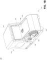
- FIGs 1A and 1B depict front and rear views, respectively, of an example holographic sight 100.
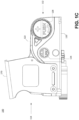
- FIGs 1C and 1D depict side views of the example holographic sight 100.
- the holographic sight 100 may be adapted to be removably attached to a suitable device such as, for example, a firearm.
- the holographic sight 100 may comprise a base 110 that is configured to releasably engage with corresponding components on a firearm in order to secure the holographic sight 100 to the firearm.
- the holographic sight 100 comprises a front end 112 and a rear end 114.
- An operator of the holographic sight 100 may look through a back window 116 situated at the rear end 114 and an aligned front window 118 situated at the front end 112.
- the area visible to the operator through the back window 116 and the aligned front window 118 may be referred to as a viewing area.
- the holographic sight 100 is adapted to impose a holographic image in the viewing area defined by the back window 116 and the front window 118.
- An elevation adjustment control 120 may be accessible via an opening formed in a housing 122 of the holographic sight 100.
- An azimuth adjustment control 124 may be accessible via an opening formed in the base 110.
- An operator may turn the elevation adjustment control 120 to adjust the vertical location of the hologram as viewed from the back window 116.
- An operator may turn the azimuth adjustment control 124 to adjust the horizontal location of the hologram as viewed from the back window 116.
- a battery cap 128 may be removed to provide access to an opening configured to receive a battery which may provide electrical power to the holographic sight 100.
- a night vision button 162 and up-down buttons 164 may extend through apertures formed in the base 110.
- An operator of the holographic sight may depress the night vision button 162 and/or the up/down buttons 164 to change the operating characteristics of the holographic sight 100. For example, depressing a particular button or combination of buttons may cause the holographic sight 100 to change its on/off state, change the brightness of the hologram, and/or toggle between normal and night vision modes
- the laser diode 134 may be configured to generate visible light which is directed toward and received at the mirror 136.
- the mirror 136 may be configured to reflect light received from the laser diode 134 toward the collimating optic 138.
- the collimating optic 138 may be configured to receive reflected light from the mirror 136 and to direct collimated light to the grating 140.
- the collimating optic 138 may be, for example, transmissive or reflective.
- the grating 140 which may be, for example, a diffraction grating, may be configured to receive the collimated light from the collimating optic 138 and to reflect diffracted light toward the image hologram 142.
- the image hologram 142 may be configured to receive light from the grating 140 and project a hologram image which may be viewed in the viewing area of the holographic sight 100.
- the holographic sight 100 displays the hologram to the operator who looks through the viewing area presented by the rear window 116.
- the hologram image may be configured to assist an operator in locating and targeting an object.
- the hologram may be a reticle, although other images may be employed.
- a collar 146 which may be referred to as a laser diode shoe, may be formed in a cylindrical shape with an interior surface having an associated interior diameter and an exterior surface having an associated exterior diameter.
- the laser diode 134 may be positioned within the collar 146 and form a frictional fit with the interior surface of the collar 146.
- a ring 148 may be positioned around the exterior surface of the collar 146 and form a frictional fit with the exterior surface of the collar 146.
- the ring 148 is received within a corresponding receptacle of the optical chassis 132.
- the ring 148 may form a frictional fit with opposing walls comprised in the corresponding receptacle of the optical chassis 132.
- a laser diode hold press may be used to apply pressure to the collar 146 during insertion of the laser diode 134, the collar 146, and the ring 148 into the corresponding receptacle of the optical chassis 132.
- the housing 122 further envelopes a bridge 152 which may be mechanically coupled to the base 110.
- the bridge 152 may form an opening 190 into which at least a portion of the first receptacle of the optical chassis 132 extends.
- An elevation adjuster assembly 154 and an azimuth adjuster assembly 156 may extend through openings 159 formed in the bridge 152 to engage portions of the first receptacle of the optical chassis 132.
- the elevation adjustment control 120 may engage with the elevation adjuster assembly 154 via an opening or aperture 155 formed in the housing 122.
- the opening or aperture 155 in the housing 122 may be formed to allow the elevation adjustment control 120 to engage with elevation adjuster assembly 154 without interference by the housing 122.
- An operator of the holographic sight 100 may turn the elevation adjustment control 120, which causes the elevation adjuster assembly 154 to increase or decrease the length of the assembly extending into the opening 190 formed by the bridge 152 and thereby increase or decrease a force applied to the first receptacle of the optical chassis 132.
- the azimuth adjustment control 124 engages with the azimuth adjuster assembly 156 via an opening 157 formed in the base 110.
- the opening 157 in the base 110 may be formed to allow the azimuth adjustment control 124 to engage with azimuth adjuster assembly 156 without interference by the base 110.
- An operator of the holographic sight 100 may turn the azimuth adjustment control 124, which causes the azimuth adjuster assembly 156 to increase or decrease the length of the assembly extending into the opening 190 formed by the bridge 152 and thereby increase or decrease a force applied to the first receptacle of the optical chassis 132,
- the housing 122 may further envelop a printed circuit board assembly 160 comprising electronics configured to power and control the holographic sight 100.
- a night vision button 162 and up-down buttons 164 may extend through a spacer 166 to engage the printed circuit board assembly 160.
- the night vision button 162 and the up-down buttons 164 may extend through corresponding openings in the base 110.
- the buttons may interface with the printed circuit board assembly 160 to change the operating characteristics of the holographic sight 100. For example, depressing a particular button or combination of buttons may cause the printed circuit board assembly 160 to change the on/off state, change the brightness of the hologram, and/or toggle between normal and night vision modes.
- the elevation adjustment control 120 may interface with the elevation adjuster assembly 154 to apply force to a portion of the optical chassis 132 and thereby adjust the elevation of the optical chassis 132.
- the azimuth adjustment control 124 may interface with the azimuth adjuster assembly 156 to apply force to a portion of the optical chassis 132 and thereby adjust the angular horizontal orientation of the optical chassis 132 relative to the base 110.
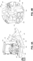
- FIG. 4A depicts an isolated perspective view of an example optical chassis 132 attached to the base 110 and with the optical components removed.
- FIG. 4B depicts an enlarged view of a portion of the example optical chassis 132.
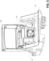
- FIG. 5 depicts a reverse perspective view of the optical chassis 132 attached to the base 110.
- the optical chassis 132 may comprise an attachment flange 220, a support member 222 integrally formed with the attachment flange 220 and extending upward from the attachment flange 220, and a unitary optical component carrier 224 integrally formed with the support member 222.
- the attachment flange 220 may be secured to the base 110 using a suitable manner which may comprise, for example, screws that extend through openings in the attachment flange 220 and into corresponding receptacles in the base 110.
- the support member 222 and the unitary optical component carrier 224 may be suspended relative to the base 110 by the attachment flange 220.
- the support member 222 of the optical chassis 132 may comprise one or more portions that are flexible such that the unitary optical component carrier 224 may be angularly moveable in horizontal and/or vertical directions relative to the attachment flange 220 and the base 110.
- the support member 222 may be compliant so as to allow for adjustment of the position of the unitary optical component carrier 224 relative to the attachment flange 220 and base 110 and thereby allow for adjusting the location of the hologram created in the operator's field of view.
- the support member 222 may comprise a first wall 240 extending upward relative to the attachment flange 220 and integrally formed with the attachment flange 220.
- the support member 222 may further comprise a second wall 244 and a flexible member 246 coupled between the first wall 240 and the second wall 244.
- the second wall 244 and the flexible member 246 may be supported by the first wall 240.
- the second wall 244 may be free to angularly move horizontally, with the flexible member 246 as a fulcrum, relative to the attachment flange 220 and base 110.
- the flexible member 246 may be coupled to the first wall 240 near the center of the first wall 240 and may be coupled to the second wall 244 near the center of the second wall 244.
- the flexible member 246 When a horizontal force is applied to the second wall 244, the flexible member 246 may be flexed or twisted allowing the second wall 244 to move or be angularly displaced horizontally relative to the first wall 240 with the flexible member 246 being a fulcrum of the movement.
- Horizontal force applied to the optical component carrier 224 may be communicated to the second horizontal wall 244 and may result in angular horizontal movement around or about the flexible member 246 of second wall 244 and the optical component carrier 224 relative to the first wall 240 and the attachment flange 220.
- the support member 222 may further comprise a first horizontal member 247 integrally formed with the second wall 244 and extending away from the unitary optical component carrier 224, a second horizontal member 248 extending toward the unitary optical component carrier 224, and a joint member 249 integrally formed with the first horizontal member 247 and the second horizontal member 248.
- the first horizontal member 247, the joint member 249, and the second horizontal member 248 may be integrally formed and together provide vertical flexibility to the unitary optical component carrier 224 relative to the attachment flange 220 and the base 110.
- the second horizontal member 248 may be flexible in a vertical direction relative to the first horizontal member 247.
- the joint member 249 may be flexible and allow for vertical movement of the second horizontal member 248 relative to the first horizontal member 247.
- the second horizontal member 248 When vertical pressure is applied to the second horizontal member 248, it may move or be displaced in a vertical direction relative to the first horizontal member 247, the attachment flange 220, and the base 110. The movement may be angular with the joint member 249 serving as a fulcrum. Vertical force applied to the unitary optical component carrier 224 may be communicated to the second horizontal member 248 and result in vertical angular movement or displacement around or about the joint member 249 of the unitary optical component carrier 224 and the second horizontal member 248 relative to the first horizontal member 247 and the attachment flange 220. As illustrated in the FIGs, multiple instances of the first horizontal member 247 and the second horizontal member 248 may be comprised in the support member 222.
- FIG. 6 depicts a perspective view of the example unitary optical component carrier 224 attached to the base 110 and with the optical components 134, 136, 138, 140, and 142 attached.
- FIG. 7 depicts the example unitary optical component carrier 224 with optical components 134, 136, 138, 140, and 142 exploded.
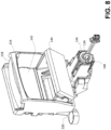
- FIG. 8 depicts a perspective view of the example unitary optical component carrier with optical components attached and without the base 110.
- FIG. 9 depicts the example optical component carrier without the base 110 and with the optical components 134, 136, 138, 140, and 142 exploded.
- the unitary optical component carrier 224 comprises a body that may serve as a bench or rack to which the optical components are attached.
- the unitary optical component carrier 224 may be integrally formed with the support member 222 which may be integrally formed with the attachment flange 220.
- the unitary optical component carrier 224 comprises a rigid body and may be substantially resistant to changes in relative distances between the optical components.
- the unitary optical component carrier 224 may be resistant to distortion and may move substantially in unison with the relative distances between the optical components 134, 136, 138, 140, and 142 remaining substantially unchanged.
- the unitary optical component carrier 224 may be made from a material that has a relatively low coefficient of thermal expansion. As a result, the relative distance between the optical components may remain substantially the same over a wide spectrum of temperature environments.
- unitary optical component carrier 224 may be manufactured from titanium.
- the unitary optical component carrier 224 may comprise a plurality of receptacles 230, 232, 234, 236, 238 configured to receive optical components.
- Each of the receptacles 230, 232, 234, 236, and 238 comprises one or more surfaces configured to receive corresponding surfaces of the appropriate optical components.
- the surface to surface mounting results in precise locating of the optical components relative to the unitary optical component carrier 224 and to each other.
- the receptacles 230, 232, 234, 236, and 238 are configured to allow the corresponding optical components to be applied from the exterior of the unitary optical component carrier 224. Mounting of the optical components from the exterior may be performed by an automated means such as, for example, by robotic handling.
- FIG. 10 depicts an isolated view of an example first receptacle 230 of an example unitary optical component carrier 224 with the laser diode 134, the collar 146, and the ring 148 aligned for insertion into the first receptacle.
- the first receptacle 230 may comprise a first set of opposing side walls 250A and 250B and a second set of opposing side walls 252A and 252B.
- the first set of opposing side walls 250A and 250B and the second set of opposing side walls 252A and 252B form a receptacle for receiving the laser diode 134. Openings 251 may be formed between adjacent sidewalls 250 and 252 which may allow opposing side walls 250A and B to be flexed apart from each other.
- the external surfaces of the sidewalls 250A, B and the sidewalls 252A, B may be substantially flat or planar and configured to receive forces.
- the sidewall 250A may comprise a substantially flat or planar external surface and may be abutted by a projection from elevation adjustment assembly 154.
- the projection of the elevation adjustment assembly 154 may apply a force in a vertical direction relative to the attachment flange 220 and the base 110.
- the sidewall 252A may comprise a substantially flat or planar external surface and may be abutted by a projection from the azimuth adjuster assembly 156.
- the projection of the azimuth adjuster assembly 156 may apply a force in a horizontal direction relative to the attachment flange 220 and the base 110.
- the laser diode 134 which may comprise a plurality of component parts, may be positioned within the collar 146.
- the collar 146 may be formed in a substantially cylindrical shape with an interior surface and an external surface.
- the interior surface of the collar 146 may be sized to receive and form a frictional interference fit with the laser diode 134.
- the ring 148 may also be formed in a substantially cylindrical shape with an interior surface and an external surface.
- the interior surface of the ring 148 may be sized and shaped to form a frictional interference fit with the external surface of the collar 146.
- the assembled combination of the diode 146, the collar 146, and the ring 148 may be inserted into the receptacle 230.
- the external surface of the ring 148 may form a frictional interference fit with internal sides of opposing side walls 250A, B and 252A, B.
- the external diameter of the ring 148 may be larger than the opening formed by the opposing side walls 250A,B and 252A, B. Accordingly, the opposing side walls 250A, B and 252A, B may flex outward to accommodate ring 148.
- FIG. 11 depicts an isolated view of an example second receptacle 232 of an example unitary optical component carrier 224 with the mirror 136 aligned for insertion into the second receptacle 232.
- the second receptacle 232 may comprise a plurality of surfaces, which may be referred to as datums, that are configured to abut corresponding surfaces of the mirror 136.
- the second receptacle 232 may comprise a first surface 260, a second surface 262, and a third surface 264 against which corresponding surfaces of the mirror may abut.
- the first surface 260, the second surface 262, and the third surface 264 may be positioned relative to each other so as to limit the movement of the mirror 136 in two or more dimensions and thereby provide relatively precise location of the mirror 136 relative to the unitary optical component carrier 224.
- An adhesive such as, for example, a glue or cement substance, may be applied to the surfaces 260, 262, and 264 of the second receptacle 232 and/or the corresponding surfaces of the mirror 136 that abut the surfaces of the second receptacle 232.
- FIG. 12 depicts an isolated view of an example third receptacle 234 of an example unitary optical component carrier 224 with a collimating optic 138 aligned for insertion into the third receptacle 234.
- the third receptacle 234 may comprise a plurality of surfaces or datums that are configured to abut corresponding surfaces of the collimating optic 138.
- the third receptacle 234 may comprise a first surface 270, a second surface 272, and a third surface 274 against which corresponding surfaces of the collimating optic 138 may abut.
- the first surface 270, the second surface 272, and the third surface 274 may be positioned relative to each other so as to limit the movement of the collimating optic 138 in two or more dimensions and thereby provide relatively precise location of the collimating optic 138 relative to the unitary optical component carrier 224.
- An adhesive such as, for example, a glue or cement substance, may be applied to the surfaces 270, 272, and 274 of the third receptacle 234 and/or the corresponding surfaces of the collimating optic 138 that abut the surfaces of the third receptacle 234.
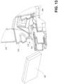
- FIG. 13 depicts an isolated view of an example fourth receptacle 236 of an example unitary optical component carrier 224 with a grating 140 aligned for insertion into the fourth receptacle 236.
- the grating 140 may be, for example, a diffraction grating such as, for example, a holographic grating.
- the fourth receptacle 236 may comprise a plurality of surfaces or datums that are configured to abut corresponding surfaces of the grating 140.
- the fourth receptacle 236 may comprise a first surface 276, a second surface 278, and a third surface 280 against which corresponding surfaces of the mirror may abut.
- the first surface 276, the second surface 278, and the third surface 280 may be positioned relative to each other so as to limit the movement of the grating 140 in two or more dimensions and thereby provide relatively precise location of the grating 140 relative to the unitary optical component carrier 224.
- An adhesive such as, for example, a glue or cement substance, may be applied to the surfaces 276, 278, and 280 of the fourth receptacle 236 and/or the corresponding surfaces of the grating 140 that abut the surfaces of the fourth receptacle 236.
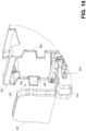
- FIG. 14 depicts an isolated view of an example fifth receptacle 238 of an example unitary optical component carrier 224 with an image hologram 142 aligned for insertion into the fifth receptacle 238.
- the fifth receptacle 238 may comprise a plurality of surfaces or datums that are configured to abut corresponding surfaces of the image hologram 142.
- the fifth receptacle 238 may comprise a first surface 282, a second surface 284, and a third surface 286 against which corresponding surfaces of the image hologram 142 may abut.
- the first surface 282, the second surface 284, and the third surface 286 may be positioned relative to each other so as to limit the movement of the image hologram 142 in two or more dimensions and thereby provide relatively precise location of the image hologram 142 relative to the unitary optical component carrier 224.
- An adhesive such as, for example, a glue or cement substance, may be applied to surfaces 282, 284, and 286 of the fifth receptacle 238 and/or the corresponding surfaces of the image hologram 142 that abut the surfaces of the fifth receptacle 238.
- a holographic sight comprising a unitary optical component carrier.
- the unitary optical component carrier may comprise a first receptacle configured to receive a laser diode, a second receptacle configured to receive a mirror, a third receptacle configured to receive a collimating optic, a fourth receptacle configured to receive a grating, and a fifth receptacle configured to receive an image hologram.
- the unitary optical component carrier provides mechanical stability and maintains the relative positioning of the optical components applied to it.
- a holographic sight comprising a unitary optical component carrier.
- the unitary optical component carrier may comprise a plurality of receptacles that are configured to receive optical components therein.
- the unitary optical component carrier may be mechanically rigid, and the optical components received therein may be maintained in their intended relative positions. Displacement of the optical components due to movement of separate receiving structures is eliminated. To the extent the unitary optical component carrier may be displaced, the rigidity of the unitary optical component carrier causes all the components to be displaced and the relative position of the optical components to be maintained.
- the unitary optical component carrier may be made of a material that has a low coefficient of thermal expansion (CTE) and may, therefore, be resistant to displacement of the optical components due to changes in temperature.
- CTE coefficient of thermal expansion
Landscapes
- Physics & Mathematics (AREA)
- Optics & Photonics (AREA)
- General Physics & Mathematics (AREA)
- Astronomy & Astrophysics (AREA)
- Engineering & Computer Science (AREA)
- General Engineering & Computer Science (AREA)
- Optical Couplings Of Light Guides (AREA)
- Telescopes (AREA)
- Mounting And Adjusting Of Optical Elements (AREA)
- Holo Graphy (AREA)
Description
- Identifying and focusing on an object located at a distance may be facilitated by use of a sight. A sight may be employed, for example, with small arms such as bows, rifles, shotguns, handguns, mounted machine guns, and grenade launchers, etc., and may assist an operator to locate and maintain focus on a target.
- Sights have been developed in many different forms and utilizing various features. For example, sights have been developed that present the operator with a hologram which may assist the operator with locating and focusing on an object. For example,
US 6 490 060 B1 is directed to a lightweight holographic sighting device for use on firearms and bows wherein optical elements are mounted separately upon a base. TheUS 9 243 868 B1 US 2015/267997 A1 is directed to a holographic image apparatus for use with a weapon, wherein optical elements are arranged on a carrier. Additionally, theUS 2016/003996 A1 is directed to components within a holographic sighting device preferably for use on firearms, wherein optical components comprise a laser diode, a mirror, a reflective collimator, a holographic integrated grating, a filter de-vice and a hologram. - Disclosed herein is a holographic sight having the features of independent claim 1. The unitary optical component carrier may comprise a single body with a plurality of receptacles for receiving optical components configured to generate a hologram. For example, the unitary optical component carrier may comprise a first receptacle configured to receive a laser diode, a second receptacle configured to receive a mirror, a third receptacle configured to receive a collimating optic, a fourth receptacle configured to receive a grating, and a fifth receptacle configured to receive an image hologram. Each of the receptacles may comprise a plurality of surfaces against which the corresponding optical component may be positioned. Light may be communicated from the laser diode to the image hologram via the mirror, collimating optic, and the grating. The unitary optical component carrier provides mechanical stability and maintains the relative positioning of the optical components received in the plurality of receptacles.
- The unitary optical component carrier may be integrally formed with a support member that extends upward from a base. According to the invention, the support member is flexible, and the unitary optical component carrier may be moveable in horizontal and vertical directions relative to the base. The support member may comprise a first portion extending upward relative to the base, a second portion extending away from the unitary optical component carrier, a third portion extending toward and integrally formed with the unitary optical component carrier, and a joint formed between the second and third portion. The first portion may
be flexible and the unitary optical component carrier angularly moveable, with the first portion serving as a fulcrum, in a horizontal direction relative to the base. When horizontal pressure is applied to the unitary optical component carrier, the unitary optical component carrier may be angularly displaced horizontally with the first portion of the support member serving as a fulcrum. The joint between the second and third portions may be flexible and the unitary optical component carrier angularly moveable, with the joint serving as a fulcrum, in a vertical direction relative to the base. When vertical pressure is applied to the unitary optical component carrier, the unitary optical component carrier may be angularly displaced vertically with the joint portion serving as a fulcrum. The mechanical stability of the unitary optical component carrier maintains the relative positioning of the optical components during displacement. - This Summary is provided to introduce a selection of concepts in a simplified form that are further described herein in the Detailed Description. This Summary is not intended to identify key features or essential features of the claimed subject matter, nor is it intended to be used to limit the scope of the claimed subject matter. Other features are described herein.
- The foregoing summary and the following additional description of the illustrative embodiments may be better understood when read in conjunction with the accompanying exemplary drawings. It is understood that the potential embodiments of the disclosed systems and implementations are not limited to those depicted. Furthermore, like reference numerals in the figures indicate like elements,
-
FIG.s 1A ,1B ,1C , and1D depict perspective views of an example assembled holographic sight. -
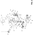
FIG. 2 is an exploded view of an example holographic sight. -
FIG. 3 is a perspective view of an example partially assembled holographic sight. -
FIG. 4A is a perspective view of an example optical chassis attached to an example base. -
FIG. 4B is a detailed view of a portion of the optical chassis. -
FIG. 5 is a perspective view of an example optical chassis attached to an example base. -
FIG. 6 is a perspective view of an example optical chassis attached to an example base and with optical components attached. -
FIG. 7 is a perspective view of an example optical chassis attached to an example base and with optical components exploded. -
FIG. 8 is a perspective view of an example optical chassis with optical components attached. -
FIG. 9 is a perspective view of an example optical chassis with optical components exploded. -
FIG. 10 is a perspective view of a portion of an example optical chassis configured to receive a laser diode. -
FIG. 11 is a perspective view of a portion of an example optical chassis configured to receive a mirror. -
FIG. 12 is a perspective view of a portion of an example optical chassis configured to receive a collimating optic. -
FIG. 13 is a perspective view of a portion of an example optical chassis configured to receive a grating. -
FIG. 14 is a perspective view of a portion of an example optical chassis configured to receive an image hologram. - Holographic sights may employ a series of optical components to generate a hologram for presentation to the operator. For example, a holographic sight may employ a laser diode that generates a light beam, a mirror that deflects the light beam, a collimating optic that receives the deflected light beam and directs collimated light, a grating that receives the collimated light and reflects light toward an image hologram that has been recorded with an image and which displays the image to the operator of the sight. Operation of the holographic sight requires that the optical components be in the intended relative positions, including distance and orientation, relative to each other. Even small variances from the intended position of even one of the optical components may negatively impact the generation of a hologram for use by the operator of the sight.
- Holographic sights may position optical components relative to each other by affixing them to structures in a holographic sight. For example, optical components such as, for example, the collimating optic and the hologram image may be affixed to an interior of a holographic sight housing. The mirror may be positioned on a podium extending from a base to which the sight housing is attached. The grating may be affixed to a moveable plate configured to rotate relative to the sight housing. Because the optical components are attached to different components which themselves may be moveable relative to each other, it may be difficult to place the optical components in their intended positions even in a controlled manufacturing environment. Furthermore, movement of any of the structures to which the optical components are attached may move the optical components from their intended positions causing degradation in the reconstruction of the hologram. For example, in a scenario the housing to which the collimating optic and hologram are attached receives an external blow, the housing and the optical components attached to it may be moved by the external blow from their intended positions which may degrade the quality of the hologram.
- The structures to which the optical components are attached may be made from different materials and may react differently to changes in temperature. For example, the holographic sight housing to which a collimating optic and hologram image may be attached may be made of steel and the podium to which the mirror component may be attached may be made from aluminum. Steel and aluminum may expand and contract in response to temperatures changes at different rates. The optical components attached to the structures, due to the different rates of thermal expansion and contraction, may be displaced from their intended positions which may degrade the quality of the hologram.
- Applicant discloses herein a holographic sight that employs a unitary optical component carrier. The unitary optical component carrier may comprise a body with a plurality of receptacles that are configured to receive optical components therein and to maintain the relative position of the optical components. The unitary optical component carrier may comprise a first receptacle configured to receive a laser diode, a second receptacle configured to receive a mirror, a third receptacle configured to receive a collimating optic, a fourth receptacle configured to receive a grating, and a fifth receptacle configured to receive an image hologram. The unitary optical component carrier may be mechanically stable, and the optical components received therein may be maintained in their intended relative positions. Displacement of the optical components due to displacement of separate receiving structures is eliminated. The unitary optical component carrier may be made of a material that has a low coefficient of thermal expansion (CTE) and may, therefore, be resistant to displacement of the optical components due to changes in temperature.
-
FIGs 1A and1B depict front and rear views, respectively, of an exampleholographic sight 100.FIGs 1C and1D depict side views of the exampleholographic sight 100. Theholographic sight 100 may be adapted to be removably attached to a suitable device such as, for example, a firearm. Theholographic sight 100 may comprise a base 110 that is configured to releasably engage with corresponding components on a firearm in order to secure theholographic sight 100 to the firearm. - The
holographic sight 100 comprises afront end 112 and arear end 114. An operator of theholographic sight 100 may look through aback window 116 situated at therear end 114 and an alignedfront window 118 situated at thefront end 112. The area visible to the operator through theback window 116 and the alignedfront window 118 may be referred to as a viewing area. Theholographic sight 100 is adapted to impose a holographic image in the viewing area defined by theback window 116 and thefront window 118. - An
elevation adjustment control 120 may be accessible via an opening formed in ahousing 122 of theholographic sight 100. Anazimuth adjustment control 124 may be accessible via an opening formed in thebase 110. An operator may turn theelevation adjustment control 120 to adjust the vertical location of the hologram as viewed from theback window 116. An operator may turn theazimuth adjustment control 124 to adjust the horizontal location of the hologram as viewed from theback window 116. Abattery cap 128 may be removed to provide access to an opening configured to receive a battery which may provide electrical power to theholographic sight 100. - A
night vision button 162 and up-downbuttons 164 may extend through apertures formed in thebase 110. An operator of the holographic sight may depress thenight vision button 162 and/or the up/downbuttons 164 to change the operating characteristics of theholographic sight 100. For example, depressing a particular button or combination of buttons may cause theholographic sight 100 to change its on/off state, change the brightness of the hologram, and/or toggle between normal and night vision modes - The
holographic sight 100 may further comprise ahood 170. Thehood 170 may be positioned over and around a portion of thehousing 122 and may be mechanically attached to thebase 110. Thehood 170 may be configured to protect thehousing 122 from impacts. -
FIG. 2 provides an exploded view of theholographic sight 100. Thehousing 122 may be mechanically coupled to thebase 110 and may have aseal 130 positioned therebetween. Thehousing 122 envelopes components of theholographic sight 100. For example, thehousing 122 may envelop anoptical chassis 132 which may also be mechanically coupled to thebase 110. Theoptical chassis 132 may comprise a rigid body with a plurality of receptacles for receiving optical components employed to create a holographic image. For example, theoptical chassis 132 may comprise a body with receptacles for receiving each of alaser diode 134, amirror 136, acollimating optic 138, agrating 140, and animage hologram 142. Thelaser diode 134 may be configured to generate visible light which is directed toward and received at themirror 136. Themirror 136 may be configured to reflect light received from thelaser diode 134 toward thecollimating optic 138. Thecollimating optic 138 may be configured to receive reflected light from themirror 136 and to direct collimated light to thegrating 140. Thecollimating optic 138 may be, for example, transmissive or reflective. The grating 140, which may be, for example, a diffraction grating, may be configured to receive the collimated light from thecollimating optic 138 and to reflect diffracted light toward theimage hologram 142. Theimage hologram 142 may be configured to receive light from the grating 140 and project a hologram image which may be viewed in the viewing area of theholographic sight 100. Theholographic sight 100 displays the hologram to the operator who looks through the viewing area presented by therear window 116. The hologram image may be configured to assist an operator in locating and targeting an object. For example, the hologram may be a reticle, although other images may be employed. - A
collar 146, which may be referred to as a laser diode shoe, may be formed in a cylindrical shape with an interior surface having an associated interior diameter and an exterior surface having an associated exterior diameter. Thelaser diode 134 may be positioned within thecollar 146 and form a frictional fit with the interior surface of thecollar 146. Aring 148 may be positioned around the exterior surface of thecollar 146 and form a frictional fit with the exterior surface of thecollar 146. Thering 148 is received within a corresponding receptacle of theoptical chassis 132. Thering 148 may form a frictional fit with opposing walls comprised in the corresponding receptacle of theoptical chassis 132. A laser diode hold press may be used to apply pressure to thecollar 146 during insertion of thelaser diode 134, thecollar 146, and thering 148 into the corresponding receptacle of theoptical chassis 132. - The
housing 122 further envelopes abridge 152 which may be mechanically coupled to thebase 110. Thebridge 152 may form anopening 190 into which at least a portion of the first receptacle of theoptical chassis 132 extends. Anelevation adjuster assembly 154 and anazimuth adjuster assembly 156 may extend throughopenings 159 formed in thebridge 152 to engage portions of the first receptacle of theoptical chassis 132. Theelevation adjustment control 120 may engage with theelevation adjuster assembly 154 via an opening oraperture 155 formed in thehousing 122. The opening oraperture 155 in thehousing 122 may be formed to allow theelevation adjustment control 120 to engage withelevation adjuster assembly 154 without interference by thehousing 122. An operator of theholographic sight 100 may turn theelevation adjustment control 120, which causes theelevation adjuster assembly 154 to increase or decrease the length of the assembly extending into theopening 190 formed by thebridge 152 and thereby increase or decrease a force applied to the first receptacle of theoptical chassis 132. - The
azimuth adjustment control 124 engages with theazimuth adjuster assembly 156 via anopening 157 formed in thebase 110. Theopening 157 in thebase 110 may be formed to allow theazimuth adjustment control 124 to engage withazimuth adjuster assembly 156 without interference by thebase 110. An operator of theholographic sight 100 may turn theazimuth adjustment control 124, which causes theazimuth adjuster assembly 156 to increase or decrease the length of the assembly extending into theopening 190 formed by thebridge 152 and thereby increase or decrease a force applied to the first receptacle of theoptical chassis 132, - The
housing 122 may further envelop a printedcircuit board assembly 160 comprising electronics configured to power and control theholographic sight 100. Anight vision button 162 and up-downbuttons 164 may extend through aspacer 166 to engage the printedcircuit board assembly 160. Thenight vision button 162 and the up-downbuttons 164 may extend through corresponding openings in thebase 110. When an operator of the holographic 100 sight depresses thenight vision button 162 and/or the up/downbuttons 164, the buttons may interface with the printedcircuit board assembly 160 to change the operating characteristics of theholographic sight 100. For example, depressing a particular button or combination of buttons may cause the printedcircuit board assembly 160 to change the on/off state, change the brightness of the hologram, and/or toggle between normal and night vision modes. -
FIG. 3 depicts a perspective view of the exampleholographic sight 100 partially assembled with thehousing 122,hood 170, and other elements removed. Theoptical chassis 132 may be mechanically coupled to the base 110 using a suitable fastening technique such as, for example, using screws. The optical components comprising thelaser diode 134, themirror 136, thecollimating optic 138, thegrating 140, and theimage hologram 142 may be received in receptacles of theoptical chassis 132. Thebridge 152 may be mechanically coupled to the base 110 using a suitable fastening technique such as, for example, using screws. A portion of theoptical chassis 132 may extend into anopening 190 defined by the bridge and thebase 110. Theelevation adjustment control 120 may interface with theelevation adjuster assembly 154 to apply force to a portion of theoptical chassis 132 and thereby adjust the elevation of theoptical chassis 132. Theazimuth adjustment control 124 may interface with theazimuth adjuster assembly 156 to apply force to a portion of theoptical chassis 132 and thereby adjust the angular horizontal orientation of theoptical chassis 132 relative to thebase 110. -
FIG. 4A depicts an isolated perspective view of an exampleoptical chassis 132 attached to thebase 110 and with the optical components removed.FIG. 4B depicts an enlarged view of a portion of the exampleoptical chassis 132.FIG. 5 depicts a reverse perspective view of theoptical chassis 132 attached to thebase 110. Theoptical chassis 132 may comprise anattachment flange 220, asupport member 222 integrally formed with theattachment flange 220 and extending upward from theattachment flange 220, and a unitaryoptical component carrier 224 integrally formed with thesupport member 222. Theattachment flange 220 may be secured to the base 110 using a suitable manner which may comprise, for example, screws that extend through openings in theattachment flange 220 and into corresponding receptacles in thebase 110. Thesupport member 222 and the unitaryoptical component carrier 224 may be suspended relative to thebase 110 by theattachment flange 220. - The
support member 222 of theoptical chassis 132 may comprise one or more portions that are flexible such that the unitaryoptical component carrier 224 may be angularly moveable in horizontal and/or vertical directions relative to theattachment flange 220 and thebase 110. Thesupport member 222 may be compliant so as to allow for adjustment of the position of the unitaryoptical component carrier 224 relative to theattachment flange 220 andbase 110 and thereby allow for adjusting the location of the hologram created in the operator's field of view. - The
support member 222 may comprise afirst wall 240 extending upward relative to theattachment flange 220 and integrally formed with theattachment flange 220. Thesupport member 222 may further comprise asecond wall 244 and aflexible member 246 coupled between thefirst wall 240 and thesecond wall 244. Thesecond wall 244 and theflexible member 246 may be supported by thefirst wall 240. Thesecond wall 244 may be free to angularly move horizontally, with theflexible member 246 as a fulcrum, relative to theattachment flange 220 andbase 110. Theflexible member 246 may be coupled to thefirst wall 240 near the center of thefirst wall 240 and may be coupled to thesecond wall 244 near the center of thesecond wall 244. When a horizontal force is applied to thesecond wall 244, theflexible member 246 may be flexed or twisted allowing thesecond wall 244 to move or be angularly displaced horizontally relative to thefirst wall 240 with theflexible member 246 being a fulcrum of the movement. Horizontal force applied to theoptical component carrier 224 may be communicated to the secondhorizontal wall 244 and may result in angular horizontal movement around or about theflexible member 246 ofsecond wall 244 and theoptical component carrier 224 relative to thefirst wall 240 and theattachment flange 220. - The
support member 222 may further comprise a firsthorizontal member 247 integrally formed with thesecond wall 244 and extending away from the unitaryoptical component carrier 224, a secondhorizontal member 248 extending toward the unitaryoptical component carrier 224, and ajoint member 249 integrally formed with the firsthorizontal member 247 and the secondhorizontal member 248. The firsthorizontal member 247, thejoint member 249, and the secondhorizontal member 248 may be integrally formed and together provide vertical flexibility to the unitaryoptical component carrier 224 relative to theattachment flange 220 and thebase 110. The secondhorizontal member 248 may be flexible in a vertical direction relative to the firsthorizontal member 247. Thejoint member 249 may be flexible and allow for vertical movement of the secondhorizontal member 248 relative to the firsthorizontal member 247. When vertical pressure is applied to the secondhorizontal member 248, it may move or be displaced in a vertical direction relative to the firsthorizontal member 247, theattachment flange 220, and thebase 110. The movement may be angular with thejoint member 249 serving as a fulcrum. Vertical force applied to the unitaryoptical component carrier 224 may be communicated to the secondhorizontal member 248 and result in vertical angular movement or displacement around or about thejoint member 249 of the unitaryoptical component carrier 224 and the secondhorizontal member 248 relative to the firsthorizontal member 247 and theattachment flange 220. As illustrated in the FIGs, multiple instances of the firsthorizontal member 247 and the secondhorizontal member 248 may be comprised in thesupport member 222. -
FIG. 6 depicts a perspective view of the example unitaryoptical component carrier 224 attached to thebase 110 and with theoptical components FIG. 7 depicts the example unitaryoptical component carrier 224 withoptical components FIG. 8 depicts a perspective view of the example unitary optical component carrier with optical components attached and without thebase 110.FIG. 9 depicts the example optical component carrier without thebase 110 and with theoptical components optical component carrier 224 comprises a body that may serve as a bench or rack to which the optical components are attached. The unitaryoptical component carrier 224 may be integrally formed with thesupport member 222 which may be integrally formed with theattachment flange 220. According to the invention, the unitaryoptical component carrier 224 comprises a rigid body and may be substantially resistant to changes in relative distances between the optical components. For example, in a scenario wherein forces are applied to thefirst receptacle 230 byelevation adjuster assembly 154 and/or by theazimuth adjuster assembly 156, the unitaryoptical component carrier 224 may be resistant to distortion and may move substantially in unison with the relative distances between theoptical components optical component carrier 224 may be made from a material that has a relatively low coefficient of thermal expansion. As a result, the relative distance between the optical components may remain substantially the same over a wide spectrum of temperature environments. In an example, unitaryoptical component carrier 224 may be manufactured from titanium. - The unitary
optical component carrier 224 may comprise a plurality ofreceptacles receptacles optical component carrier 224 and to each other. Thereceptacles optical component carrier 224. Mounting of the optical components from the exterior may be performed by an automated means such as, for example, by robotic handling. The optical components may be secured in thereceptacles
FIG. 10 depicts an isolated view of an examplefirst receptacle 230 of an example unitaryoptical component carrier 224 with thelaser diode 134, thecollar 146, and thering 148 aligned for insertion into the first receptacle. Thefirst receptacle 230 may comprise a first set of opposingside walls side walls side walls side walls laser diode 134.Openings 251 may be formed between adjacent sidewalls 250 and 252 which may allow opposingside walls 250A and B to be flexed apart from each other. The external surfaces of the sidewalls 250A, B and the sidewalls 252A, B may be substantially flat or planar and configured to receive forces. For example, thesidewall 250A may comprise a substantially flat or planar external surface and may be abutted by a projection fromelevation adjustment assembly 154. The projection of theelevation adjustment assembly 154 may apply a force in a vertical direction relative to theattachment flange 220 and thebase 110. Thesidewall 252A may comprise a substantially flat or planar external surface and may be abutted by a projection from theazimuth adjuster assembly 156. The projection of theazimuth adjuster assembly 156 may apply a force in a horizontal direction relative to theattachment flange 220 and thebase 110. - The
laser diode 134, which may comprise a plurality of component parts, may be positioned within thecollar 146. Thecollar 146 may be formed in a substantially cylindrical shape with an interior surface and an external surface. The interior surface of thecollar 146 may be sized to receive and form a frictional interference fit with thelaser diode 134. Thering 148 may also be formed in a substantially cylindrical shape with an interior surface and an external surface. The interior surface of thering 148 may be sized and shaped to form a frictional interference fit with the external surface of thecollar 146. The assembled combination of thediode 146, thecollar 146, and thering 148 may be inserted into thereceptacle 230. The assembleddiode 146,collar 146, andring 148 may be inserted by applying a force to thecollar 146 using a tool such as insertion tool that may be configured to apply a force to thecollar 146 without applying a force to thelaser diode 134. - The external surface of the
ring 148 may form a frictional interference fit with internal sides of opposingside walls 250A, B and 252A, B. The external diameter of thering 148 may be larger than the opening formed by the opposingside walls 250A,B and 252A, B. Accordingly, the opposingside walls 250A, B and 252A, B may flex outward to accommodatering 148. -
FIG. 11 depicts an isolated view of an examplesecond receptacle 232 of an example unitaryoptical component carrier 224 with themirror 136 aligned for insertion into thesecond receptacle 232. Thesecond receptacle 232 may comprise a plurality of surfaces, which may be referred to as datums, that are configured to abut corresponding surfaces of themirror 136. For example, thesecond receptacle 232 may comprise afirst surface 260, asecond surface 262, and athird surface 264 against which corresponding surfaces of the mirror may abut. Thefirst surface 260, thesecond surface 262, and thethird surface 264 may be positioned relative to each other so as to limit the movement of themirror 136 in two or more dimensions and thereby provide relatively precise location of themirror 136 relative to the unitaryoptical component carrier 224. An adhesive such as, for example, a glue or cement substance, may be applied to thesurfaces second receptacle 232 and/or the corresponding surfaces of themirror 136 that abut the surfaces of thesecond receptacle 232. -
FIG. 12 depicts an isolated view of an examplethird receptacle 234 of an example unitaryoptical component carrier 224 with acollimating optic 138 aligned for insertion into thethird receptacle 234. Thethird receptacle 234 may comprise a plurality of surfaces or datums that are configured to abut corresponding surfaces of thecollimating optic 138. For example, thethird receptacle 234 may comprise afirst surface 270, asecond surface 272, and athird surface 274 against which corresponding surfaces of thecollimating optic 138 may abut. Thefirst surface 270, thesecond surface 272, and thethird surface 274 may be positioned relative to each other so as to limit the movement of thecollimating optic 138 in two or more dimensions and thereby provide relatively precise location of thecollimating optic 138 relative to the unitaryoptical component carrier 224. An adhesive such as, for example, a glue or cement substance, may be applied to thesurfaces third receptacle 234 and/or the corresponding surfaces of thecollimating optic 138 that abut the surfaces of thethird receptacle 234. -
FIG. 13 depicts an isolated view of an examplefourth receptacle 236 of an example unitaryoptical component carrier 224 with a grating 140 aligned for insertion into thefourth receptacle 236. The grating 140 may be, for example, a diffraction grating such as, for example, a holographic grating. Thefourth receptacle 236 may comprise a plurality of surfaces or datums that are configured to abut corresponding surfaces of thegrating 140. For example, thefourth receptacle 236 may comprise afirst surface 276, asecond surface 278, and athird surface 280 against which corresponding surfaces of the mirror may abut. Thefirst surface 276, thesecond surface 278, and thethird surface 280 may be positioned relative to each other so as to limit the movement of the grating 140 in two or more dimensions and thereby provide relatively precise location of the grating 140 relative to the unitaryoptical component carrier 224. An adhesive such as, for example, a glue or cement substance, may be applied to thesurfaces fourth receptacle 236 and/or the corresponding surfaces of the grating 140 that abut the surfaces of thefourth receptacle 236. -
FIG. 14 depicts an isolated view of an examplefifth receptacle 238 of an example unitaryoptical component carrier 224 with animage hologram 142 aligned for insertion into thefifth receptacle 238. Thefifth receptacle 238 may comprise a plurality of surfaces or datums that are configured to abut corresponding surfaces of theimage hologram 142. For example, thefifth receptacle 238 may comprise afirst surface 282, asecond surface 284, and athird surface 286 against which corresponding surfaces of theimage hologram 142 may abut. Thefirst surface 282, thesecond surface 284, and thethird surface 286 may be positioned relative to each other so as to limit the movement of theimage hologram 142 in two or more dimensions and thereby provide relatively precise location of theimage hologram 142 relative to the unitaryoptical component carrier 224. An adhesive such as, for example, a glue or cement substance, may be applied tosurfaces fifth receptacle 238 and/or the corresponding surfaces of theimage hologram 142 that abut the surfaces of thefifth receptacle 238. - Accordingly, Applicant has disclosed a holographic sight comprising a unitary optical component carrier. The unitary optical component carrier may comprise a first receptacle configured to receive a laser diode, a second receptacle configured to receive a mirror, a third receptacle configured to receive a collimating optic, a fourth receptacle configured to receive a grating, and a fifth receptacle configured to receive an image hologram. The unitary optical component carrier provides mechanical stability and maintains the relative positioning of the optical components applied to it.
- Accordingly, Applicant has disclosed a holographic sight comprising a unitary optical component carrier. The unitary optical component carrier may comprise a plurality of receptacles that are configured to receive optical components therein. The unitary optical component carrier may be mechanically rigid, and the optical components received therein may be maintained in their intended relative positions. Displacement of the optical components due to movement of separate receiving structures is eliminated. To the extent the unitary optical component carrier may be displaced, the rigidity of the unitary optical component carrier causes all the components to be displaced and the relative position of the optical components to be maintained. The unitary optical component carrier may be made of a material that has a low coefficient of thermal expansion (CTE) and may, therefore, be resistant to displacement of the optical components due to changes in temperature. A holographic sight comprising the unitary optical component carrier offers improved ease of assembly and greater operational accuracy across a wide spectrum of operating environments.
- It will be appreciated that while illustrative embodiments have been disclosed, the scope of potential embodiments is not limited to those explicitly described and is only defined by the appended claims. For example, while an example holographic sight is described with a particular number of optical components, different numbers of optical components may be comprised in a holographic sight consistent with the disclosure. Embodiments may have optical components arranged in formations other than as in the examples described herein. Likewise, embodiments may employ support members that provide similar functionality, but which are configured differently than as explicitly described herein.
- Although the features and elements may be described herein in particular combinations, each feature or element may be used alone, without the other features and elements, and/or in various combinations with or without other features and elements as far as it is covered by the scope of protection conferred by the appended claims.
Claims (17)
- A holographic sight (100) comprising a chassis (132) havinga base (110);a support member (222) integrally formed with the base (110) and extending upward from the base (110);a plurality of optical components including a laser diode (134), a mirror (136), a collimating optic (138), a diffraction grating (140), and an image hologram (142), anda unitary optical component carrier (224) integrally formed with the support member (222), the unitary optical component carrier (224) comprising a first receptacle (230) configured to receive the laser diode (134), a second receptacle (232) configured to receive the mirror (136), a third receptacle (234) configured to receive the collimating optic (138), a fourth receptacle (236) configured to receive the diffraction grating (140), and a fifth receptacle (238) configured to receive the image hologram (142),wherein the support member (222) is flexible and the unitary optical component carrier (224) angularly movable, andwherein the unitary optical component carrier (224) comprises a rigid body and is substantially resistant to changes in relative distances between the optical components (134, 136, 138, 140, and 142).
- Holographic sight (100) of claim 1, wherein the unitary optical component carrier (224) angularly moveable, with the support member (222) as a fulcrum, in horizontal and vertical directions relative to the base.
- Holographic sight (100) of any of claims 1 or 2, wherein the support member (222) comprises a first support member portion extending upward relative to the base (110), a second support member portion extending away from the unitary optical component carrier (224), and a third support member portion extending toward the unitary optical component carrier (224), the third support member portion integrally formed with the unitary optical component carrier (224).
- Holographic sight (100) of any of claims 1 to 3, wherein the first support member portion is flexible and the unitary optical component carrier (224) angularly moveable, with the first support member portion as a fulcrum, in a horizontal direction relative to the base (110).
- Holographic sight (100) of any of claims 1 to 4, wherein the third support member portion is flexible and the unitary optical component carrier (224) moveable in a vertical direction relative to the base (110).
- Holographic sight (100) of any of claims 1 to 5, wherein the first receptacle (230) configured to receive the laser diode (134) comprises a first set of opposing walls (250A, 250B) and a second set of opposing walls (252A, 252B), the first set of opposing walls (250A, 250B) and the second set opposing side walls (252A, 252B) forming an opening (251) configured to receive the laser diode (134).
- Holographic sight (100) of claim 6,
wherein the opening (251) configured to receive the laser diode (134) is configured to receive a cylindrical collar (146) in which the laser diode (134) is positioned. - Holographic sight (100) of claim 7,
wherein the first set of opposing walls (250A, 250B) and the second set of opposing walls (252A, 252B) have recesses formed between, the opposing walls configured to flex outward to accommodate the cylindrical collar (146). - Holographic sight (100) of claim 8, wherein an external side of at least one of the first set of opposing walls (250A, 250B) is substantially flat and configured to receive a force in a horizontal direction relative to the base (110).
- Holographic sight (100) of claim 8, wherein an external side of at least one of the second set of opposing walls (252A, 252B) is substantially flat and configured to receive a force in a vertical direction relative to the base (110).
- Holographic sight (100) of any of claims 1 to 10, wherein the second receptacle (232) configured to receive the mirror (136) comprises at least first surface and a second surface configured to abut surfaces of the mirror (136).
- Holographic sight (100) of any of claims 1 to 11, wherein the third receptacle (234) configured to receive the collimating optic (138) comprises at least a first surface and a second surface configured to abut surfaces of the collimating optic (138).
- Holographic sight (100) of any of claims 1 to 12, wherein the fourth receptacle (236) configured to receive the diffraction grating (140) comprises at least a first surface and a second surface configured to abut surfaces of the diffraction grating (140).
- Holographic sight (100) of any of claims 1 to 13, wherein the fifth receptacle (138) configured to receive the image hologram (142) comprises at least a first surface and a second surface configured to abut surfaces of the image hologram (142).
- Holographic sight (100) of claim 1,wherein the support member (222) is integrally formed with the unitary optical component carrier (224), the support member (222) comprising a first portion that is flexible in a horizontal direction and a second portion that is flexible in vertical direction, the unitary optical component carrier (224) horizontally and vertically moveable relative to the support member (222)wherein the first receptacle (230) comprises a first set of opposing side walls (250A, 250B) and a second set of opposing side walls (252A, 252B).
- Holographic sight of claim 15,wherein the support member (222) comprises a first upstanding wall (240), a second upstanding wall (244), and a flexible member (246) connected between the first upstanding wall (240) and the second upstanding wall (244), the unitary optical component carrier (224) integrally formed with the second upstanding wall (244),wherein a horizontal force applied to the unitary optical component carrier (224) is communicated to the second upstanding wall (244) and angularly displaces in a horizontal direction, with the flexible member (246) as a fulcrum, the second upstanding wall (244) and the unitary optical component carrier (224).
- Holographic sight of any of claims 15 or 16,wherein the support member (222) comprises a first horizontal member (247), a second horizontal member (248), and a joint (249) integrally formed between the first horizontal member (247) and the second horizontal member (248), the unitary optical component carrier (224) integrally formed with the second horizontal member (248),wherein a vertical force applied to the unitary optical component carrier (224) is communicated to the second horizontal member (248) and angularly displaces in a vertical direction, with the joint (249) as a fulcrum, the second horizontal member (248) and the unitary optical component carrier (224).
Priority Applications (1)
| Application Number | Priority Date | Filing Date | Title |
|---|---|---|---|
| EP25173244.2A EP4571387A3 (en) | 2019-11-21 | 2020-11-16 | Unitary carrier for holographic components |
Applications Claiming Priority (2)
| Application Number | Priority Date | Filing Date | Title |
|---|---|---|---|
| US16/691,117 US11467391B2 (en) | 2019-11-21 | 2019-11-21 | Unitary carrier for holographic components |
| PCT/US2020/060707 WO2021141670A2 (en) | 2019-11-21 | 2020-11-16 | Unitary carrier for holographic components |
Related Child Applications (1)
| Application Number | Title | Priority Date | Filing Date |
|---|---|---|---|
| EP25173244.2A Division EP4571387A3 (en) | 2019-11-21 | 2020-11-16 | Unitary carrier for holographic components |
Publications (3)
| Publication Number | Publication Date |
|---|---|
| EP4034924A2 EP4034924A2 (en) | 2022-08-03 |
| EP4034924A4 EP4034924A4 (en) | 2024-02-28 |
| EP4034924B1 true EP4034924B1 (en) | 2025-04-30 |
Family
ID=75973898
Family Applications (2)
| Application Number | Title | Priority Date | Filing Date |
|---|---|---|---|
| EP25173244.2A Pending EP4571387A3 (en) | 2019-11-21 | 2020-11-16 | Unitary carrier for holographic components |
| EP20912540.0A Active EP4034924B1 (en) | 2019-11-21 | 2020-11-16 | Unitary carrier for holographic components |
Family Applications Before (1)
| Application Number | Title | Priority Date | Filing Date |
|---|---|---|---|
| EP25173244.2A Pending EP4571387A3 (en) | 2019-11-21 | 2020-11-16 | Unitary carrier for holographic components |
Country Status (6)
| Country | Link |
|---|---|
| US (1) | US11467391B2 (en) |
| EP (2) | EP4571387A3 (en) |
| JP (1) | JP7507239B2 (en) |
| KR (1) | KR102745941B1 (en) |
| CA (1) | CA3156140A1 (en) |
| WO (1) | WO2021141670A2 (en) |
Families Citing this family (11)
| Publication number | Priority date | Publication date | Assignee | Title |
|---|---|---|---|---|
| US11098980B2 (en) | 2019-11-21 | 2021-08-24 | Eotech, Llc | Modular weapon sight assembly |
| US11467391B2 (en) | 2019-11-21 | 2022-10-11 | Eotech, Llc | Unitary carrier for holographic components |
| US11449003B2 (en) * | 2019-11-21 | 2022-09-20 | Eotech, Llc | Position adjustment in holographic sight |
| USD961714S1 (en) * | 2019-11-21 | 2022-08-23 | Eotech, Llc | Weapon sight |
| US11486675B2 (en) * | 2019-11-21 | 2022-11-01 | Eotech, Llc | Weapon sight with tapered housing |
| US11391904B2 (en) | 2019-11-21 | 2022-07-19 | Eotech, Llc | Temperature stabilized holographic sight |
| USD975818S1 (en) * | 2020-03-10 | 2023-01-17 | Sheltered Wings, Inc. | Gun sight device |
| USD1042716S1 (en) * | 2021-10-21 | 2024-09-17 | Aimpoint Ab | Sight |
| USD1089513S1 (en) * | 2021-12-01 | 2025-08-19 | Huanic Corporation | Gun sight |
| USD1060590S1 (en) | 2022-01-17 | 2025-02-04 | Eotech, Llc | Gun sight |
| USD1044999S1 (en) * | 2022-04-21 | 2024-10-01 | Teidore LLC | Firearm sight |
Family Cites Families (75)
| Publication number | Priority date | Publication date | Assignee | Title |
|---|---|---|---|---|
| US4191471A (en) | 1972-05-24 | 1980-03-04 | Grumman Aerospace Corporation | Aircraft armament alignment |
| US3994597A (en) | 1974-12-26 | 1976-11-30 | Calder William E | Optical sight with variable illumination |
| FR2533684B1 (en) | 1982-09-24 | 1986-12-19 | Thomson Csf | HIGH HEAD POINTING SIGHT USED AS SHOOTING SIGHT |
| JP2554629B2 (en) * | 1986-06-13 | 1996-11-13 | 株式会社東芝 | Optical fiber collimator |
| US4940324A (en) | 1988-05-25 | 1990-07-10 | American Advantage Company | Electronic sight having a larger horizontal viewing field than a vertical viewing field and method of making same |
| US5090805A (en) | 1990-08-15 | 1992-02-25 | Blount, Inc. | Bow sight with projected reticle aiming spot |
| US5134798A (en) | 1991-02-22 | 1992-08-04 | Lee Roberto R | Two sight mount |
| US5369888A (en) | 1993-01-13 | 1994-12-06 | Kay; Ira M. | Wide field of view reflex gunsight |
| JPH0783599A (en) | 1993-09-14 | 1995-03-28 | Asia Opt Kk | Aiming scope |
| US5483362A (en) | 1994-05-17 | 1996-01-09 | Environmental Research Institute Of Michigan | Compact holographic sight |
| US5815936A (en) * | 1994-05-17 | 1998-10-06 | Environmental Research Institute Of Michigan | Detachable hologram assembly and windage/elevation adjuster for a compact holographic sight |
| JPH09184998A (en) * | 1996-01-08 | 1997-07-15 | Fuji Xerox Co Ltd | Optical scanning device |
| US6000667A (en) | 1996-10-30 | 1999-12-14 | Litton Systems, Inc. | Mounting assembly for optical sight |
| US6490060B1 (en) * | 1999-10-14 | 2002-12-03 | Eotech, Inc. | Lightweight holographic sight |
| US20030074824A1 (en) | 2001-10-18 | 2003-04-24 | Sarl Patrick Arachequesne | Mount for a sighting device on a firearm |
| US7181882B2 (en) | 2003-02-03 | 2007-02-27 | Martin Woodbury | Dual-zero sight for a firearm |
| JP4019995B2 (en) | 2003-03-31 | 2007-12-12 | 松下電工株式会社 | Line indicator |
| JP2005345549A (en) * | 2004-05-31 | 2005-12-15 | Sumitomo Electric Ind Ltd | Optical module |
| US7225578B2 (en) | 2005-01-06 | 2007-06-05 | Eotech Acquisition Corp. | Aiming sight having fixed light emitting diode (LED) array and rotatable collimator |
| US7145703B2 (en) | 2005-01-27 | 2006-12-05 | Eotech Acquisition Corp. | Low profile holographic sight and method of manufacturing same |
| JP2008090257A (en) | 2006-06-30 | 2008-04-17 | Konica Minolta Opto Inc | Projection unit |
| US20080020355A1 (en) | 2006-07-18 | 2008-01-24 | Lockheed Martin Corporation | Variable beam boresight device |
| US7784192B2 (en) | 2007-01-18 | 2010-08-31 | L-3 Insight Technology Incorporated | SWIR vision and illumination devices |
| US7634866B2 (en) | 2007-03-09 | 2009-12-22 | Meopta optika s.r.o. | Gun site having removable adjustable modules |
| US8056245B2 (en) | 2007-04-03 | 2011-11-15 | L-3 Insight Technology Incorporated | Method and apparatus for aligning collimated light beams |
| KR100906159B1 (en) | 2007-07-06 | 2009-07-03 | 정인 | Large Diameter Dot Sight Device |
| WO2009023970A1 (en) | 2007-08-22 | 2009-02-26 | Quantum Leap Research Inc. | Lighting assembly featuring a plurality of light sources with a windage and elevation control mechanism therefor |
| DE102007063407A1 (en) | 2007-12-31 | 2009-07-02 | Schmidt & Bender Gmbh & Co. Kg | reflex sight |
| US20090193705A1 (en) | 2008-02-06 | 2009-08-06 | Truglo, Inc. | Sighting Device with Trajectory Compensation |
| US20100162611A1 (en) | 2008-12-31 | 2010-07-01 | Machining Technologies, Inc. | Adjustable base for an optic |
| US8156679B1 (en) | 2009-01-14 | 2012-04-17 | Swan Richard E | Accessory module with integrated electronic devices |
| EP2513698B1 (en) | 2009-12-18 | 2016-05-04 | Redring AB | Optical aiming device with light sensor for adjusting reticle light intensity |
| US20110228366A1 (en) * | 2010-03-22 | 2011-09-22 | Shou LIU | Hoe optical system for holographic sight |
| US8240075B1 (en) | 2011-01-13 | 2012-08-14 | Mullin James K | Adjustable bases for sighting devices |
| US8186093B1 (en) | 2011-07-08 | 2012-05-29 | International Trade and Technologies, Inc. | Dot sight device of plurality of calibers |
| US20130008072A1 (en) | 2011-07-08 | 2013-01-10 | Sung Giu Chung | Dot sight device |
| US8296991B1 (en) | 2011-07-08 | 2012-10-30 | International Trade and Technologies, Inc. | Digital machinegun optic with bullet drop compensation mount |
| US8966805B2 (en) | 2011-09-02 | 2015-03-03 | Trijicon, Inc. | Reflex sight |
| WO2013086144A1 (en) | 2011-12-06 | 2013-06-13 | Laser Energetics, Inc. | Weapon-mountable non-lethal optical security device |
| US10061069B2 (en) | 2012-06-22 | 2018-08-28 | Luminit Llc | Method for design and manufacturing of optics for holographic sight |
| KR101375457B1 (en) | 2012-09-27 | 2014-03-17 | 정보선 | Dot-sighting device for a handgun |
| EP2943736B1 (en) | 2013-01-11 | 2017-05-10 | Surefire, LLC | Gun sight |
| US9057584B2 (en) | 2013-04-12 | 2015-06-16 | International Trade and Technologies, Inc. | Modular universal machinegun sight with bullet drop compensation device |
| EP3019812B1 (en) * | 2013-07-09 | 2018-09-05 | Zieger, Cory | Modular holographic sighting system |
| US20160327365A1 (en) | 2013-07-15 | 2016-11-10 | OptiFlow, Inc. | Holographic weapon sight with laser management system |
| EP3022514B1 (en) | 2013-07-15 | 2021-09-08 | Optiflow, LLC | Compact weapon sight and method of stabilizing an output wavelength of a weapon sight |
| US9423212B2 (en) | 2014-01-13 | 2016-08-23 | Leupold & Stevens, Inc. | Reflex sight adjustments |
| US9482803B2 (en) | 2014-05-09 | 2016-11-01 | L-3 Communications, Warrior Systems Division, Eo Tech, Inc. | Integrated filter and grating in an aiming sight |
| US9316460B2 (en) | 2014-07-30 | 2016-04-19 | Ncstar, Inc. | One hand operational combo sight device |
| AU2015333702B2 (en) | 2014-10-13 | 2020-06-11 | Wilcox Industries Corp. | Combined Reflex And Laser Sight With Elevation Macro-Adjustment Mechanism |
| US9243868B1 (en) | 2014-12-15 | 2016-01-26 | The United States Of America, As Represented By The Secretary, Department Of Homeland Security | Reticle providing maximized danger space |
| RU2582900C1 (en) | 2014-12-31 | 2016-04-27 | Открытое акционерное общество "Научно-производственный комплекс "ЭЛАРА" имени Г.А. Ильенко (ОАО "ЭЛАРА") | Laser gyroscope |
| US20160313089A1 (en) | 2015-04-21 | 2016-10-27 | OptiFlow, Inc. | Externally adjustable gun sight |
| EP3314314A4 (en) * | 2015-06-26 | 2018-06-20 | Ziel Optics, Inc. | Holographic weapon sight with optimized beam angles |
| US10254532B2 (en) | 2015-06-26 | 2019-04-09 | Ziel Optics, Inc. | Hybrid holographic sight |
| US10591249B2 (en) | 2015-11-16 | 2020-03-17 | Hookshottactical, Llc | Camera sight device for a weapon |
| US10175029B2 (en) | 2016-01-15 | 2019-01-08 | Wilcox Industries Corp. | Combined reflex and laser sight with co-aligned iron sights |
| US10267597B2 (en) | 2016-01-21 | 2019-04-23 | Lasermax Inc | Compact dynamic head up display |
| US10095089B2 (en) | 2016-05-17 | 2018-10-09 | Raytheon Company | Lens mount assembly |
| IL249353B (en) | 2016-12-01 | 2022-07-01 | Felix Sidelkovsky | METHODS, SYSTEMS, CIRCUITS, COMPONENTS, DEVICES, INSTRUMENTS, ASSEMBLIES AND COMPUTER OPERATING CODE, FOR FIREARMS |
| US10921091B2 (en) | 2017-04-07 | 2021-02-16 | James Borrico | Holographic weapon sight |
| WO2019068165A1 (en) | 2017-10-06 | 2019-04-11 | Raytheon Canada Limited | Open frame reflex pivot mechanics |
| US10704862B2 (en) | 2017-11-14 | 2020-07-07 | International Trade and Technologies, Inc. | Next generation machine gun sight (NexGen MGS) |
| SE542668C2 (en) | 2018-03-07 | 2020-06-23 | Aimpoint Ab | Reflex sight |
| US10345077B1 (en) | 2018-06-19 | 2019-07-09 | Hel Technologies, Llc | Holographic optical element with edge lighting |
| US10345587B1 (en) | 2018-06-19 | 2019-07-09 | Hel Technologies, Llc | Technique for selectively projecting different holograms using a single holographic optical element |
| US11079202B2 (en) | 2018-07-07 | 2021-08-03 | Sensors Unlimited, Inc. | Boresighting peripherals to digital weapon sights |
| US10801813B2 (en) | 2018-11-07 | 2020-10-13 | N2 Imaging Systems, LLC | Adjustable-power data rail on a digital weapon sight |
| US11249383B2 (en) | 2019-02-24 | 2022-02-15 | Drew Nolle Walker | First person shooting camera mount |
| WO2020250758A1 (en) | 2019-06-10 | 2020-12-17 | 株式会社小糸製作所 | Optical unit and vehicle lamp |
| US11098980B2 (en) | 2019-11-21 | 2021-08-24 | Eotech, Llc | Modular weapon sight assembly |
| US11391904B2 (en) | 2019-11-21 | 2022-07-19 | Eotech, Llc | Temperature stabilized holographic sight |
| US11449003B2 (en) | 2019-11-21 | 2022-09-20 | Eotech, Llc | Position adjustment in holographic sight |
| US11486675B2 (en) | 2019-11-21 | 2022-11-01 | Eotech, Llc | Weapon sight with tapered housing |
| US11467391B2 (en) | 2019-11-21 | 2022-10-11 | Eotech, Llc | Unitary carrier for holographic components |
-
2019
- 2019-11-21 US US16/691,117 patent/US11467391B2/en active Active
-
2020
- 2020-11-16 JP JP2022529438A patent/JP7507239B2/en active Active
- 2020-11-16 KR KR1020227017723A patent/KR102745941B1/en active Active
- 2020-11-16 EP EP25173244.2A patent/EP4571387A3/en active Pending
- 2020-11-16 CA CA3156140A patent/CA3156140A1/en active Pending
- 2020-11-16 WO PCT/US2020/060707 patent/WO2021141670A2/en not_active Ceased
- 2020-11-16 EP EP20912540.0A patent/EP4034924B1/en active Active
Also Published As
| Publication number | Publication date |
|---|---|
| EP4034924A2 (en) | 2022-08-03 |
| KR102745941B1 (en) | 2024-12-23 |
| EP4034924A4 (en) | 2024-02-28 |
| EP4571387A3 (en) | 2025-08-27 |
| JP2023502134A (en) | 2023-01-20 |
| KR20220105644A (en) | 2022-07-27 |
| WO2021141670A2 (en) | 2021-07-15 |
| CA3156140A1 (en) | 2021-07-15 |
| WO2021141670A3 (en) | 2021-10-28 |
| US20210157119A1 (en) | 2021-05-27 |
| JP7507239B2 (en) | 2024-06-27 |
| EP4571387A2 (en) | 2025-06-18 |
| US11467391B2 (en) | 2022-10-11 |
Similar Documents
| Publication | Publication Date | Title |
|---|---|---|
| EP4042092B1 (en) | POSITIONING IN A HOLOGRAPHIC SIGHT | |
| US11467391B2 (en) | Unitary carrier for holographic components | |
| EP4042091B1 (en) | Temperature stabilized holographic sight | |
| EP4045867B1 (en) | Weapon sight with tapered housing | |
| US11435162B2 (en) | Modular weapon sight assembly | |
| US8056245B2 (en) | Method and apparatus for aligning collimated light beams | |
| CA3155581C (en) | Temperature stabilized holographic sight |
Legal Events
| Date | Code | Title | Description |
|---|---|---|---|
| STAA | Information on the status of an ep patent application or granted ep patent |
Free format text: STATUS: THE INTERNATIONAL PUBLICATION HAS BEEN MADE |
|
| PUAI | Public reference made under article 153(3) epc to a published international application that has entered the european phase |
Free format text: ORIGINAL CODE: 0009012 |
|
| STAA | Information on the status of an ep patent application or granted ep patent |
Free format text: STATUS: REQUEST FOR EXAMINATION WAS MADE |
|
| 17P | Request for examination filed |
Effective date: 20220427 |
|
| AK | Designated contracting states |
Kind code of ref document: A2 Designated state(s): AL AT BE BG CH CY CZ DE DK EE ES FI FR GB GR HR HU IE IS IT LI LT LU LV MC MK MT NL NO PL PT RO RS SE SI SK SM TR |
|
| DAV | Request for validation of the european patent (deleted) | ||
| DAX | Request for extension of the european patent (deleted) | ||
| REG | Reference to a national code |
Ref legal event code: R079 Free format text: PREVIOUS MAIN CLASS: G02B0005320000 Ref country code: DE Ref document number: 602020050646 Country of ref document: DE Ipc: F41G0001300000 |
|
| A4 | Supplementary search report drawn up and despatched |
Effective date: 20240125 |
|
| RIC1 | Information provided on ipc code assigned before grant |
Ipc: G02B 23/10 20060101ALI20240119BHEP Ipc: F41G 1/30 20060101AFI20240119BHEP |
|
| GRAP | Despatch of communication of intention to grant a patent |
Free format text: ORIGINAL CODE: EPIDOSNIGR1 |
|
| STAA | Information on the status of an ep patent application or granted ep patent |
Free format text: STATUS: GRANT OF PATENT IS INTENDED |
|
| INTG | Intention to grant announced |
Effective date: 20241120 |
|
| GRAS | Grant fee paid |
Free format text: ORIGINAL CODE: EPIDOSNIGR3 |
|
| GRAA | (expected) grant |
Free format text: ORIGINAL CODE: 0009210 |
|
| STAA | Information on the status of an ep patent application or granted ep patent |
Free format text: STATUS: THE PATENT HAS BEEN GRANTED |
|
| AK | Designated contracting states |
Kind code of ref document: B1 Designated state(s): AL AT BE BG CH CY CZ DE DK EE ES FI FR GB GR HR HU IE IS IT LI LT LU LV MC MK MT NL NO PL PT RO RS SE SI SK SM TR |
|
| P01 | Opt-out of the competence of the unified patent court (upc) registered |
Free format text: CASE NUMBER: APP_13864/2025 Effective date: 20250320 |
|
| REG | Reference to a national code |
Ref country code: CH Ref legal event code: EP Ref country code: GB Ref legal event code: FG4D |
|
| REG | Reference to a national code |
Ref country code: IE Ref legal event code: FG4D |
|
| REG | Reference to a national code |
Ref country code: DE Ref legal event code: R096 Ref document number: 602020050646 Country of ref document: DE |
|
| REG | Reference to a national code |
Ref country code: CH Ref legal event code: PK Free format text: BERICHTIGUNGEN |
|
| REG | Reference to a national code |
Ref country code: CH Ref legal event code: PK Free format text: BERICHTIGUNGEN |
|
| RIN2 | Information on inventor provided after grant (corrected) |
Inventor name: HEATH, ANTHONY Inventor name: MCMILLEN, DEANNA, KAY Inventor name: OLSON, JAMES |
|
| REG | Reference to a national code |
Ref country code: NL Ref legal event code: MP Effective date: 20250430 |
|
| REG | Reference to a national code |
Ref country code: AT Ref legal event code: MK05 Ref document number: 1790364 Country of ref document: AT Kind code of ref document: T Effective date: 20250430 |
|
| PG25 | Lapsed in a contracting state [announced via postgrant information from national office to epo] |
Ref country code: FI Free format text: LAPSE BECAUSE OF FAILURE TO SUBMIT A TRANSLATION OF THE DESCRIPTION OR TO PAY THE FEE WITHIN THE PRESCRIBED TIME-LIMIT Effective date: 20250430 Ref country code: PT Free format text: LAPSE BECAUSE OF FAILURE TO SUBMIT A TRANSLATION OF THE DESCRIPTION OR TO PAY THE FEE WITHIN THE PRESCRIBED TIME-LIMIT Effective date: 20250901 Ref country code: ES Free format text: LAPSE BECAUSE OF FAILURE TO SUBMIT A TRANSLATION OF THE DESCRIPTION OR TO PAY THE FEE WITHIN THE PRESCRIBED TIME-LIMIT Effective date: 20250430 |
|
| REG | Reference to a national code |
Ref country code: LT Ref legal event code: MG9D |
|
| PG25 | Lapsed in a contracting state [announced via postgrant information from national office to epo] |
Ref country code: NO Free format text: LAPSE BECAUSE OF FAILURE TO SUBMIT A TRANSLATION OF THE DESCRIPTION OR TO PAY THE FEE WITHIN THE PRESCRIBED TIME-LIMIT Effective date: 20250730 Ref country code: GR Free format text: LAPSE BECAUSE OF FAILURE TO SUBMIT A TRANSLATION OF THE DESCRIPTION OR TO PAY THE FEE WITHIN THE PRESCRIBED TIME-LIMIT Effective date: 20250731 |
|
| PG25 | Lapsed in a contracting state [announced via postgrant information from national office to epo] |
Ref country code: PL Free format text: LAPSE BECAUSE OF FAILURE TO SUBMIT A TRANSLATION OF THE DESCRIPTION OR TO PAY THE FEE WITHIN THE PRESCRIBED TIME-LIMIT Effective date: 20250430 Ref country code: NL Free format text: LAPSE BECAUSE OF FAILURE TO SUBMIT A TRANSLATION OF THE DESCRIPTION OR TO PAY THE FEE WITHIN THE PRESCRIBED TIME-LIMIT Effective date: 20250430 |
|
| PG25 | Lapsed in a contracting state [announced via postgrant information from national office to epo] |
Ref country code: BG Free format text: LAPSE BECAUSE OF FAILURE TO SUBMIT A TRANSLATION OF THE DESCRIPTION OR TO PAY THE FEE WITHIN THE PRESCRIBED TIME-LIMIT Effective date: 20250430 |
|
| PG25 | Lapsed in a contracting state [announced via postgrant information from national office to epo] |
Ref country code: HR Free format text: LAPSE BECAUSE OF FAILURE TO SUBMIT A TRANSLATION OF THE DESCRIPTION OR TO PAY THE FEE WITHIN THE PRESCRIBED TIME-LIMIT Effective date: 20250430 |
|
| PG25 | Lapsed in a contracting state [announced via postgrant information from national office to epo] |
Ref country code: AT Free format text: LAPSE BECAUSE OF FAILURE TO SUBMIT A TRANSLATION OF THE DESCRIPTION OR TO PAY THE FEE WITHIN THE PRESCRIBED TIME-LIMIT Effective date: 20250430 |
|
| PG25 | Lapsed in a contracting state [announced via postgrant information from national office to epo] |
Ref country code: RS Free format text: LAPSE BECAUSE OF FAILURE TO SUBMIT A TRANSLATION OF THE DESCRIPTION OR TO PAY THE FEE WITHIN THE PRESCRIBED TIME-LIMIT Effective date: 20250731 |
|
| PG25 | Lapsed in a contracting state [announced via postgrant information from national office to epo] |
Ref country code: IS Free format text: LAPSE BECAUSE OF FAILURE TO SUBMIT A TRANSLATION OF THE DESCRIPTION OR TO PAY THE FEE WITHIN THE PRESCRIBED TIME-LIMIT Effective date: 20250830 |
|
| PG25 | Lapsed in a contracting state [announced via postgrant information from national office to epo] |
Ref country code: LV Free format text: LAPSE BECAUSE OF FAILURE TO SUBMIT A TRANSLATION OF THE DESCRIPTION OR TO PAY THE FEE WITHIN THE PRESCRIBED TIME-LIMIT Effective date: 20250430 |
|
| PGFP | Annual fee paid to national office [announced via postgrant information from national office to epo] |
Ref country code: DE Payment date: 20251128 Year of fee payment: 6 |
|
| PGFP | Annual fee paid to national office [announced via postgrant information from national office to epo] |
Ref country code: GB Payment date: 20251127 Year of fee payment: 6 |
|
| PG25 | Lapsed in a contracting state [announced via postgrant information from national office to epo] |
Ref country code: SM Free format text: LAPSE BECAUSE OF FAILURE TO SUBMIT A TRANSLATION OF THE DESCRIPTION OR TO PAY THE FEE WITHIN THE PRESCRIBED TIME-LIMIT Effective date: 20250430 Ref country code: DK Free format text: LAPSE BECAUSE OF FAILURE TO SUBMIT A TRANSLATION OF THE DESCRIPTION OR TO PAY THE FEE WITHIN THE PRESCRIBED TIME-LIMIT Effective date: 20250430 |
|
| PGFP | Annual fee paid to national office [announced via postgrant information from national office to epo] |
Ref country code: FR Payment date: 20251125 Year of fee payment: 6 |
|
| PG25 | Lapsed in a contracting state [announced via postgrant information from national office to epo] |
Ref country code: CZ Free format text: LAPSE BECAUSE OF FAILURE TO SUBMIT A TRANSLATION OF THE DESCRIPTION OR TO PAY THE FEE WITHIN THE PRESCRIBED TIME-LIMIT Effective date: 20250430 |
|
| PG25 | Lapsed in a contracting state [announced via postgrant information from national office to epo] |
Ref country code: EE Free format text: LAPSE BECAUSE OF FAILURE TO SUBMIT A TRANSLATION OF THE DESCRIPTION OR TO PAY THE FEE WITHIN THE PRESCRIBED TIME-LIMIT Effective date: 20250430 |
|
| PG25 | Lapsed in a contracting state [announced via postgrant information from national office to epo] |
Ref country code: SK Free format text: LAPSE BECAUSE OF FAILURE TO SUBMIT A TRANSLATION OF THE DESCRIPTION OR TO PAY THE FEE WITHIN THE PRESCRIBED TIME-LIMIT Effective date: 20250430 |
|
| PG25 | Lapsed in a contracting state [announced via postgrant information from national office to epo] |
Ref country code: IT Free format text: LAPSE BECAUSE OF FAILURE TO SUBMIT A TRANSLATION OF THE DESCRIPTION OR TO PAY THE FEE WITHIN THE PRESCRIBED TIME-LIMIT Effective date: 20250430 |
|
| REG | Reference to a national code |
Ref country code: DE Ref legal event code: R097 Ref document number: 602020050646 Country of ref document: DE |
|
| PG25 | Lapsed in a contracting state [announced via postgrant information from national office to epo] |
Ref country code: RO Free format text: LAPSE BECAUSE OF FAILURE TO SUBMIT A TRANSLATION OF THE DESCRIPTION OR TO PAY THE FEE WITHIN THE PRESCRIBED TIME-LIMIT Effective date: 20250430 |
|
| PLBE | No opposition filed within time limit |
Free format text: ORIGINAL CODE: 0009261 |
|
| STAA | Information on the status of an ep patent application or granted ep patent |
Free format text: STATUS: NO OPPOSITION FILED WITHIN TIME LIMIT |
|
| REG | Reference to a national code |
Ref country code: CH Ref legal event code: L10 Free format text: ST27 STATUS EVENT CODE: U-0-0-L10-L00 (AS PROVIDED BY THE NATIONAL OFFICE) Effective date: 20260311 |
|
| 26N | No opposition filed |
Effective date: 20260202 |