EP4033880B1 - Feederhouse assemblies having biased lock pins, agricultural harvesters, and related methods - Google Patents
Feederhouse assemblies having biased lock pins, agricultural harvesters, and related methods Download PDFInfo
- Publication number
- EP4033880B1 EP4033880B1 EP20743274.1A EP20743274A EP4033880B1 EP 4033880 B1 EP4033880 B1 EP 4033880B1 EP 20743274 A EP20743274 A EP 20743274A EP 4033880 B1 EP4033880 B1 EP 4033880B1
- Authority
- EP
- European Patent Office
- Prior art keywords
- header
- lock pin
- frame
- latch
- feederhouse
- Prior art date
- Legal status (The legal status is an assumption and is not a legal conclusion. Google has not performed a legal analysis and makes no representation as to the accuracy of the status listed.)
- Active
Links
Images



Classifications
-
- A—HUMAN NECESSITIES
- A01—AGRICULTURE; FORESTRY; ANIMAL HUSBANDRY; HUNTING; TRAPPING; FISHING
- A01D—HARVESTING; MOWING
- A01D41/00—Combines, i.e. harvesters or mowers combined with threshing devices
- A01D41/12—Details of combines
- A01D41/14—Mowing tables
- A01D41/16—Devices for coupling mowing tables to conveyors
-
- A—HUMAN NECESSITIES
- A01—AGRICULTURE; FORESTRY; ANIMAL HUSBANDRY; HUNTING; TRAPPING; FISHING
- A01D—HARVESTING; MOWING
- A01D41/00—Combines, i.e. harvesters or mowers combined with threshing devices
- A01D41/06—Combines with headers
Definitions
- US-2003/0172637 discloses a mechanism for attaching a harvesting assembly to a combine harvester. Pins of a latching mechanism are carried at a lower front portion of the feederhouse and are engaged within openings defined by the harvesting assembly. The pins serve to operatively secure the harvesting assembly against the front of the feederhouse.
- An agricultural harvester includes a chassis, a feederhouse mounted to the chassis and having an inlet end, a frame adjacent the inlet end, a header lock pin extending from the frame, a biasing member coupled to the frame and the header lock pin, a rotatable latch coupled to the frame and the header lock pin, a processing system carried by the chassis and structured to receive crop material from the feederhouse, and a grain bin carried by the chassis and structured to receive grain from the processing system.
- the frame defines a generally planar face configured to receive a harvesting header.
- the biasing member is configured to urge the header lock pin outward to lock the harvesting header to the frame.
- the latch in a first position at least partially protrudes from the frame and retains the header lock pin in an inward position. The latch in a second position permits the header lock pin to travel outward urged by the biasing member.
- the terms “comprising,” “including,” “containing,” “characterized by,” and grammatical equivalents thereof are inclusive or open-ended terms that do not exclude additional, unrecited elements or method steps, but also include the more restrictive terms “consisting of” and “consisting essentially of” and grammatical equivalents thereof.
- the term "may” with respect to a material, structure, feature, or method act indicates that such is contemplated for use in implementation of an embodiment of the disclosure, and such term is used in preference to the more restrictive term “is” so as to avoid any implication that other, compatible materials, structures, features, and methods usable in combination therewith should or must be excluded.
- the term "substantially" in reference to a given parameter, property, or condition means and includes to a degree that one of ordinary skill in the art would understand that the given parameter, property, or condition is met with a degree of variance, such as within acceptable manufacturing tolerances.
- the parameter, property, or condition may be at least 90.0% met, at least 95.0% met, at least 99.0% met, or even at least 99.9% met.
- FIG. 1 illustrates an example agricultural harvester embodied as a combine harvester 100.
- the example combine harvester 100 is merely illustrative, and other machines and/or implements with like functionality may deploy certain embodiments disclosed herein, such as windrowers or forage harvesters, without limitation.
- the example combine harvester 100 is shown in FIG. 1 without a header attached, and includes a feederhouse assembly 200 carried by a chassis 104 supported by wheels 106.
- An operator cab 102 is mounted to the chassis 104.
- Hydraulic cylinders 108 are shown affixed to the underside of the feederhouse assembly 200 on one end and to the chassis 104 on the other end.
- the feederhouse assembly 200 may move ( e.g., up and down, tilt) based on actuation of the hydraulic cylinders 108, which causes a detachably coupled header to also be raised, lowered, and/or tilted.
- a rotating shaft 110 may be configured to provide mechanical power to a header during operation of the combine harvester 100.
- the rotating shaft 1 10 may be configured to operate at various speeds, as described in, for example, U.S. Patent 9,434,252, "Power Takeoff Drive System for a Vehicle," issued September 6, 2016 .
- the combine harvester 100 cuts crop materials ( e . g ., using the header), wherein the cut crop materials are delivered to the front end of the feederhouse assembly 200. Such crop materials are moved upwardly and rearwardly within and beyond the feederhouse assembly 200 ( e . g ., by a conveyer) until reaching a processing system 112 comprising a thresher rotor.
- the thresher rotor may comprise a single, transverse rotor, such as that found in a Gleaner ® Super Series Combine by AGCO.
- Other designs may be used, such as axial-based, twin rotor, or hybrid designs.
- the thresher rotor processes the crop materials in known manner and passes a portion of the crop material (e . g ., heavier chaff or corn stalks, without limitation) toward the rear of the combine harvester 100 and another portion (e.g ., grain and possibly light chaff) through a cleaning process.
- the crop materials undergo threshing and separating operations.
- the crop materials are threshed and separated by the thresher rotor operating in cooperation with well-known foraminous processing members in the form of threshing concave assemblies and separator grate assemblies, with the grain (and possibly light chaff) escaping through the concave assemblies and the grate assemblies and to a cleaning system located beneath the processor to facilitate the cleaning of the heavier crop material.
- Bulkier stalk and leaf materials are generally retained by the concave assemblies and the grate assemblies and are discharged out from the processing system 112 and ultimately out of the rear of the combine harvester 100.
- the cleaned grain that drops to the bottom of the cleaning system is delivered by a conveying mechanism that transports the grain to an elevator, which conveys the grain to a grain bin 114 located at the top of the combine harvester 100. Any remaining chaff and partially or unthreshed grain is recirculated through the processing system 112 via a tailings return conveying mechanism.
- the processing system 112 may include conditioning rollers, rather than separation devices.
- FIG. 2 is a simplified view of the feederhouse assembly 200 shown in FIG. 1 .
- a feederhouse 202 has an inlet end 204 and an outlet end 206. Crop material entering the feederhouse assembly 200 from the harvesting header travels from the inlet end 204 toward the outlet end 206 on the way to the processing system 112 ( FIG. 1 ).
- the harvesting header is coupled to the feederhouse 202 by a frame 208, which is adjustable to control the orientation of the harvesting header with respect to the combine harvester 100. Control of the harvesting header is important to enable an operator to properly harvest crops. Adjustment of the frame 208 also facilitates connecting and disconnecting the harvesting header because the frame 208 can be positioned to match the orientation of the harvesting header.
- the frame 208 may define a generally planar face 210 configured to receive a harvesting header.
- One or more rotatable latches 212 may protrude from the face 210 when no harvesting header is attached to the frame 208.
- the latches 212 may be coupled to header lock pins 214 extending from the frame 208.
- the header lock pins 214 may extend from opposite sides of the frame 208.
- the header lock pins 214 may be configured to extend outward from the frame 208 and lock a harvesting header to the frame 208.
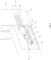
- FIG. 3 is a simplified detail view of the frame 208 shown in FIG. 2 , with portions of the face 210 removed for illustrative purposes.
- a biasing member 302 (shown behind the face 210 in dashed lines) is coupled to the frame 208 and the header lock pin 214 and is configured to urge the header lock pin 214 outward ( i . e ., to the right, in the orientation shown in FIG. 3 ) to lock a harvesting header to the frame 208.
- the biasing member 302 is depicted as a compression coil spring, but may be any selected device to push the header lock pin 214 outward ( e . g ., an extension spring or an air spring, without limitation).
- a cable 304 is also coupled to the header lock pin 214, so that a tensile force on the cable 304 pulls the header lock pin 214 inward.
- the cable 304 may be coupled to a handle, an actuator, or other device to apply the tensile force to the header lock pin 214.
- the cable 304 may be replaced with a bar or other linking mechanism.
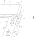
- FIG. 4 is an exploded view showing the latch 212 and the header lock pin 214.
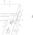
- FIG. 5 shows the latch 212 and the header lock pin 214 in another position.
- the latch 212 defines a locking indent 310
- the header lock pin 214 has a protrusion 312 extending from the header lock pin 214.
- the protrusion 312 may rest in the locking indent 310 when the header lock pin 214 is pulled inward, as shown in FIG. 5 .
- the latch 212 may therefore hold the header lock pin 214 in the inward position. Because an end of the latch 212 extends past the face 210 of the frame 208, the latch 212 may be moved to the position shown in FIG. 4 upon contact with an object, such as a harvesting header.
- the latch 212 may then release the header lock pin 214, which, urged by the biasing member 302, may spring outward, locking the harvesting header in place.
- FIG. 6 is a simplified flow chart illustrating a method 600 of connecting a harvesting header to an agricultural harvester and disconnecting the harvesting header from the agricultural harvester, such as the combine harvester 100 shown in FIG. 1 and having a feederhouse assembly 200 as shown in FIG. 2 . As shown in block 602 of FIG. 6 , the agricultural harvester moves toward the harvesting header.
- a second force is applied to pull the header lock pin inward to release the harvesting header from the frame.
- the second force is typically a tensile force on the cable 304 shown in FIG. 3 .
- the second force is applied to overcome an outward force of a spring on the header lock pin.
- the header lock pin may be secured in an inward position to the latch. The agricultural harvester then backs away from the harvesting header, disconnected from the harvesting header.
- Embodiment 3 The feederhouse assembly of Embodiment 1 or Embodiment 2, further comprising a cable coupled to the header lock pin, wherein a tensile force on the cable pulls the header lock pin inward.
- Embodiment 7 The feederhouse assembly of any one of Embodiment 1 through Embodiment 6, wherein the latch defines a locking indent, wherein the header lock pin has a protrusion, and wherein in the second position of the latch, the protrusion is disposed within the locking indent.
- Embodiment 10 An agricultural harvester comprising a chassis, the feederhouse of any one of Embodiment 1 through claim 9 mounted to the chassis, a processing system carried by the chassis and structured to receive crop material from the feederhouse, and a grain bin carried by the chassis and structured to receive grain from the processing system.
- Embodiment 12 The method of Embodiment 11, further comprising applying a second force to pull the header lock pin inward to release the harvesting header from the frame.
- Embodiment 13 The method of Embodiment 12, wherein applying the second force to pull the header lock pin inward comprises securing the header lock pin in an inward position to the latch.
- Embodiment 14 The method of Embodiment 12 or Embodiment 13, wherein applying a second force from the harvesting header on the latch comprises overcoming a force of a spring on the header lock pin.
Landscapes
- Life Sciences & Earth Sciences (AREA)
- Environmental Sciences (AREA)
- Harvester Elements (AREA)
- Engineering & Computer Science (AREA)
- Mechanical Engineering (AREA)
- Soil Sciences (AREA)
Description
- This disclosure relates to self-propelled crop-harvesting machines that can carry a header supported on the front end thereof, and particularly to header attachment mechanisms and methods.
- Self-propelled agricultural harvesters are well known and include, by way of example, combine harvesters, windrowers and forage harvesters, all of which typically include a frame or chassis, an operator cab, an engine, and ground-engaging wheels or tracks. A cutting or pick-up header is often carried by the harvester, the header typically being considerably wider than the harvester and mounted to the front side of a feederhouse.
- Crop material collected by the header is conveyed into the feederhouse before being conveyed in a generally rearward direction to crop processing apparatus. In the case of a combine harvester, the processing apparatus serves to thresh the crop material and separate grain therefrom, whereas, in the case of a forage harvester or windrower the crop material is typically passed through conditioning rollers.
- The header is typically separable from the agricultural harvester, and may be connected by latches, hooks, or other means. Connecting and disconnecting the header can be difficult and dangerous because of the size and weight of the header and the agricultural harvester, and because the operations typically occur in the field. Thus, an operational error can lead to injury or death, particularly if an operator is near the connection point
-
US-2003/0172637 discloses a mechanism for attaching a harvesting assembly to a combine harvester. Pins of a latching mechanism are carried at a lower front portion of the feederhouse and are engaged within openings defined by the harvesting assembly. The pins serve to operatively secure the harvesting assembly against the front of the feederhouse. - In some embodiments, a feederhouse assembly for an agricultural harvester includes a feederhouse having an inlet end, a frame adjacent the inlet end of the feederhouse, a header lock pin extending from the frame, a biasing member coupled to the frame and the header lock pin, and a rotatable latch coupled to the frame and the header lock pin. The frame defines a generally planar face configured to receive a harvesting header. The biasing member is configured to urge the header lock pin outward to lock the harvesting header to the frame. The latch in a first position at least partially protrudes from the frame and retains the header lock pin in an inward position. The latch in a second position permits the header lock pin to travel outward urged by the biasing member.
- A method includes moving an agricultural harvester toward a harvesting header, applying a force from the harvesting header on a latch at least partially protruding from a frame of a feederhouse carried by the agricultural harvester, pushing the latch to release a header lock pin from an inward position, and urging the header lock pin outward to lock the harvesting header to the frame.
- An agricultural harvester includes a chassis, a feederhouse mounted to the chassis and having an inlet end, a frame adjacent the inlet end, a header lock pin extending from the frame, a biasing member coupled to the frame and the header lock pin, a rotatable latch coupled to the frame and the header lock pin, a processing system carried by the chassis and structured to receive crop material from the feederhouse, and a grain bin carried by the chassis and structured to receive grain from the processing system. The frame defines a generally planar face configured to receive a harvesting header. The biasing member is configured to urge the header lock pin outward to lock the harvesting header to the frame. The latch in a first position at least partially protrudes from the frame and retains the header lock pin in an inward position. The latch in a second position permits the header lock pin to travel outward urged by the biasing member.
- While the specification concludes with claims particularly pointing out and distinctly claiming what are regarded as embodiments of the present disclosure, various features and advantages of embodiments of the disclosure may be more readily ascertained from the following description of example embodiments of the disclosure when read in conjunction with the accompanying drawings, in which:
-
FIG. 1 is a simplified front perspective view of an example agricultural harvester; -
FIG. 2 illustrates a feederhouse assembly, which may be a part of the agricultural harvester shown inFIG. 1 ; -
FIG. 3 is a simplified detail view of a frame of the feederhouse assembly shown inFIG. 2 ; -
FIG. 4 is an exploded view of a latch of the feederhouse assembly shown inFIG. 2 ; -
FIG. 5 is an exploded view of the latch shown inFIG. 4 in another position; and -
FIG. 6 is a simplified flow chart illustrating an example method of connecting and disconnecting a harvesting header. - The illustrations presented herein are not actual views of any agricultural harvester or portion thereof, but are merely idealized representations that are employed to describe example embodiments of the present disclosure. Additionally, elements common between figures may retain the same numerical designation.
- The following description provides specific details of embodiments of the present disclosure in order to provide a thorough description thereof. However, a person of ordinary skill in the art will understand that the embodiments of the disclosure may be practiced without employing many such specific details. Indeed, the embodiments of the disclosure may be practiced in conjunction with conventional techniques employed in the industry. In addition, the description provided below does not include all elements to form a complete structure or assembly. Only those process acts and structures necessary to understand the embodiments of the disclosure are described in detail below. Additional conventional acts and structures may be used. Also note, the drawings accompanying the application are for illustrative purposes only, and are thus not drawn to scale.
- As used herein, the terms "comprising," "including," "containing," "characterized by," and grammatical equivalents thereof are inclusive or open-ended terms that do not exclude additional, unrecited elements or method steps, but also include the more restrictive terms "consisting of" and "consisting essentially of" and grammatical equivalents thereof.
- As used herein, the term "may" with respect to a material, structure, feature, or method act indicates that such is contemplated for use in implementation of an embodiment of the disclosure, and such term is used in preference to the more restrictive term "is" so as to avoid any implication that other, compatible materials, structures, features, and methods usable in combination therewith should or must be excluded.
- As used herein, the term "configured" refers to a size, shape, material composition, and arrangement of one or more of at least one structure and at least one apparatus facilitating operation of one or more of the structure and the apparatus in a predetermined way.
- As used herein, the singular forms following "a," "an," and "the" are intended to include the plural forms as well, unless the context clearly indicates otherwise.
- As used herein, the term "and/or" includes any and all combinations of one or more of the associated listed items.
- As used herein, spatially relative terms, such as "beneath," "below," "lower," "bottom," "above," "upper," "top," "front," "rear," "left," "right," and the like, may be used for ease of description to describe one element's or feature's relationship to another element(s) or feature(s) as illustrated in the figures. Unless otherwise specified, the spatially relative terms are intended to encompass different orientations of the materials in addition to the orientation depicted in the figures.
- As used herein, the term "substantially" in reference to a given parameter, property, or condition means and includes to a degree that one of ordinary skill in the art would understand that the given parameter, property, or condition is met with a degree of variance, such as within acceptable manufacturing tolerances. By way of example, depending on the particular parameter, property, or condition that is substantially met, the parameter, property, or condition may be at least 90.0% met, at least 95.0% met, at least 99.0% met, or even at least 99.9% met.
- As used herein, the term "about" used in reference to a given parameter is inclusive of the stated value and has the meaning dictated by the context (e.g., it includes the degree of error associated with measurement of the given parameter).
-
FIG. 1 illustrates an example agricultural harvester embodied as acombine harvester 100. In the context of the present disclosure, the example combineharvester 100 is merely illustrative, and other machines and/or implements with like functionality may deploy certain embodiments disclosed herein, such as windrowers or forage harvesters, without limitation. The example combineharvester 100 is shown inFIG. 1 without a header attached, and includes afeederhouse assembly 200 carried by achassis 104 supported by wheels 106. Anoperator cab 102 is mounted to thechassis 104. In some embodiments, other or additional forms of travel may be used, such as tracks. Hydraulic cylinders 108 are shown affixed to the underside of thefeederhouse assembly 200 on one end and to thechassis 104 on the other end. Thefeederhouse assembly 200 may move (e.g., up and down, tilt) based on actuation of the hydraulic cylinders 108, which causes a detachably coupled header to also be raised, lowered, and/or tilted. A rotating shaft 110 may be configured to provide mechanical power to a header during operation of thecombine harvester 100. The rotating shaft 1 10 may be configured to operate at various speeds, as described in, for example,U.S. Patent 9,434,252, "Power Takeoff Drive System for a Vehicle," issued September 6, 2016 - In general, the combine harvester 100 cuts crop materials (e.g., using the header), wherein the cut crop materials are delivered to the front end of the
feederhouse assembly 200. Such crop materials are moved upwardly and rearwardly within and beyond the feederhouse assembly 200 (e.g., by a conveyer) until reaching aprocessing system 112 comprising a thresher rotor. In one embodiment, the thresher rotor may comprise a single, transverse rotor, such as that found in a Gleaner® Super Series Combine by AGCO. Other designs may be used, such as axial-based, twin rotor, or hybrid designs. The thresher rotor processes the crop materials in known manner and passes a portion of the crop material (e.g., heavier chaff or corn stalks, without limitation) toward the rear of thecombine harvester 100 and another portion (e.g., grain and possibly light chaff) through a cleaning process. In theprocessing system 112, the crop materials undergo threshing and separating operations. In other words, the crop materials are threshed and separated by the thresher rotor operating in cooperation with well-known foraminous processing members in the form of threshing concave assemblies and separator grate assemblies, with the grain (and possibly light chaff) escaping through the concave assemblies and the grate assemblies and to a cleaning system located beneath the processor to facilitate the cleaning of the heavier crop material. Bulkier stalk and leaf materials are generally retained by the concave assemblies and the grate assemblies and are discharged out from theprocessing system 112 and ultimately out of the rear of thecombine harvester 100. The cleaned grain that drops to the bottom of the cleaning system is delivered by a conveying mechanism that transports the grain to an elevator, which conveys the grain to a grain bin 114 located at the top of thecombine harvester 100. Any remaining chaff and partially or unthreshed grain is recirculated through theprocessing system 112 via a tailings return conveying mechanism. Because combine processing is known to those having ordinary skill in the art, further discussion thereof is omitted here for brevity. In embodiments in which the agricultural harvester is a windrower or forage harvester, theprocessing system 112 may include conditioning rollers, rather than separation devices. -
FIG. 2 is a simplified view of thefeederhouse assembly 200 shown inFIG. 1 . As shown, afeederhouse 202 has aninlet end 204 and anoutlet end 206. Crop material entering thefeederhouse assembly 200 from the harvesting header travels from theinlet end 204 toward theoutlet end 206 on the way to the processing system 112 (FIG. 1 ). The harvesting header is coupled to thefeederhouse 202 by aframe 208, which is adjustable to control the orientation of the harvesting header with respect to thecombine harvester 100. Control of the harvesting header is important to enable an operator to properly harvest crops. Adjustment of theframe 208 also facilitates connecting and disconnecting the harvesting header because theframe 208 can be positioned to match the orientation of the harvesting header. - The
frame 208 may define a generallyplanar face 210 configured to receive a harvesting header. One or more rotatable latches 212 (two are depicted inFIG. 2 ) may protrude from theface 210 when no harvesting header is attached to theframe 208. Thelatches 212 may be coupled to header lock pins 214 extending from theframe 208. As shown, the header lock pins 214 may extend from opposite sides of theframe 208. The header lock pins 214 may be configured to extend outward from theframe 208 and lock a harvesting header to theframe 208. -
FIG. 3 is a simplified detail view of theframe 208 shown inFIG. 2 , with portions of theface 210 removed for illustrative purposes. A biasing member 302 (shown behind theface 210 in dashed lines) is coupled to theframe 208 and theheader lock pin 214 and is configured to urge theheader lock pin 214 outward (i.e., to the right, in the orientation shown inFIG. 3 ) to lock a harvesting header to theframe 208. The biasingmember 302 is depicted as a compression coil spring, but may be any selected device to push theheader lock pin 214 outward (e.g., an extension spring or an air spring, without limitation). A cable 304 is also coupled to theheader lock pin 214, so that a tensile force on the cable 304 pulls theheader lock pin 214 inward. The cable 304 may be coupled to a handle, an actuator, or other device to apply the tensile force to theheader lock pin 214. In certain embodiments, the cable 304 may be replaced with a bar or other linking mechanism. - The
latch 212 is rotationally secured to theframe 208 at apivot pin 306, and a portion of thelatch 212 is urged outward from theface 210 of theframe 208 by another biasingmember 308. -
FIG. 4 is an exploded view showing thelatch 212 and theheader lock pin 214.FIG. 5 shows thelatch 212 and theheader lock pin 214 in another position. Thelatch 212 defines a lockingindent 310, and theheader lock pin 214 has aprotrusion 312 extending from theheader lock pin 214. Theprotrusion 312 may rest in the lockingindent 310 when theheader lock pin 214 is pulled inward, as shown inFIG. 5 . Thelatch 212 may therefore hold theheader lock pin 214 in the inward position. Because an end of thelatch 212 extends past theface 210 of theframe 208, thelatch 212 may be moved to the position shown inFIG. 4 upon contact with an object, such as a harvesting header. Thelatch 212 may then release theheader lock pin 214, which, urged by the biasingmember 302, may spring outward, locking the harvesting header in place. - In the position shown in
FIG. 5 , a portion of thelatch 212 protrudes from theface 210 of theframe 208. In the position shown inFIG. 4 , thelatch 212 may be flush with theface 210 of theframe 208. -
FIG. 6 is a simplified flow chart illustrating amethod 600 of connecting a harvesting header to an agricultural harvester and disconnecting the harvesting header from the agricultural harvester, such as thecombine harvester 100 shown inFIG. 1 and having afeederhouse assembly 200 as shown inFIG. 2 . As shown inblock 602 ofFIG. 6 , the agricultural harvester moves toward the harvesting header. - In
block 604, a first force is applied from the harvesting header on a latch at least partially protruding from a generally planar face of a frame of a feederhouse carried by the agricultural harvester. - In
block 606, the latch is pushed to release a header lock pin from an inward position. - In block 608, the header lock pin is urged outward to lock the harvesting header to the frame. Urging the header lock pin outward secures the harvesting header to the frame without intervention by any person located proximal to the coupling location so long as the harvesting header and the frame are properly aligned. To secure the harvesting header, the header lock pin may be extended into a hole defined in a frame of the harvesting header.
Block 604, block 606, and block 608 may typically occur at the same time as part of a single motion of the agricultural harvester toward the harvesting header. - In
block 610, a second force is applied to pull the header lock pin inward to release the harvesting header from the frame. The second force is typically a tensile force on the cable 304 shown inFIG. 3 . The second force is applied to overcome an outward force of a spring on the header lock pin. As a result of pulling the header lock pin inward, the header lock pin may be secured in an inward position to the latch. The agricultural harvester then backs away from the harvesting header, disconnected from the harvesting header. - Advantages of including a header lock pin in the feederhouse assembly disclosed herein is that the harvesting header may be automatically connected to the agricultural harvester without intervention by any person located proximal to the coupling location. This may increase safety by enabling the operator to remain away from pinch points. The disconnection of the harvesting header may be automatic (e.g., by using an actuator controlled by a controller in the operator cab) or may be manual (e.g., an operator may pull on a handle connected to the cable 304).
- Additional non-limiting example embodiments of the disclosure are described below.
- All references cited herein are incorporated herein in their entireties. If there is a conflict between definitions herein and in an incorporated reference, the definition herein shall control.
- While the present disclosure has been described herein with respect to certain illustrated embodiments, those of ordinary skill in the art will recognize and appreciate that it is not so limited. Rather, many additions, deletions, and modifications to the illustrated embodiments may be made without departing from the scope of the disclosure as hereinafter claimed, including legal equivalents thereof. In addition, features from one embodiment may be combined with features of another embodiment while still being encompassed within the scope as contemplated by the inventors. Further, embodiments of the disclosure have utility with different and various machine types and configurations.
- Embodiment 3: The feederhouse assembly of Embodiment 1 or Embodiment 2, further comprising a cable coupled to the header lock pin, wherein a tensile force on the cable pulls the header lock pin inward.
- Embodiment 4: The feederhouse assembly of any one of Embodiment 1 through Embodiment 3, wherein in the second position, the latch is flush with the generally planar face of the frame.
- Embodiment 5: The feederhouse assembly of any one of Embodiment 1 through Embodiment 4, wherein the latch further comprises another biasing member configured to urge the latch toward the first position.
- Embodiment 6: The feederhouse assembly of any one of Embodiment 1 through Embodiment 5. wherein the latch pivots about a pivot pin.
- Embodiment 7: The feederhouse assembly of any one of Embodiment 1 through Embodiment 6, wherein the latch defines a locking indent, wherein the header lock pin has a protrusion, and wherein in the second position of the latch, the protrusion is disposed within the locking indent.
- Embodiment 8: The feederhouse assembly of any one of claim 1 through claim 3, wherein the latch in the first position protrudes from generally planar face of the frame.
- Embodiment 9: The feederhouse assembly of claim 8, wherein the harvesting header pushes the latch in to the second position.
- Embodiment 10: An agricultural harvester comprising a chassis, the feederhouse of any one of Embodiment 1 through claim 9 mounted to the chassis, a processing system carried by the chassis and structured to receive crop material from the feederhouse, and a grain bin carried by the chassis and structured to receive grain from the processing system.
- Embodiment 11: A method comprising moving an agricultural harvester toward a harvesting header, applying a force from the harvesting header on a latch at least partially protruding from a frame of a feederhouse carried by the agricultural harvester, pushing the latch to release a header lock pin from an inward position, and urging the header lock pin outward to lock the harvesting header to the frame.
- Embodiment 12: The method of Embodiment 11, further comprising applying a second force to pull the header lock pin inward to release the harvesting header from the frame.
- Embodiment 13: The method of Embodiment 12, wherein applying the second force to pull the header lock pin inward comprises securing the header lock pin in an inward position to the latch.
- Embodiment 14: The method of Embodiment 12 or Embodiment 13, wherein applying a second force from the harvesting header on the latch comprises overcoming a force of a spring on the header lock pin.
- Embodiment 15: The method of any one of Embodiment 11 through Embodiment 14, wherein urging the header lock pin outward to lock the harvesting header to the frame comprises securing the harvesting header to the frame without intervention by any person located proximal to a coupling location.
- Embodiment 16: The method of any one of Embodiment 11 through Embodiment 15, wherein urging the header lock pin outward to lock the harvesting header to the frame comprises extending the header lock pin into a hole defined in a frame of the harvesting header.
- Embodiment 17: The method of any one of Embodiment 11 through Embodiment 16, wherein applying a force from the harvesting header on a latch comprises applying a force from the harvesting header on a latch at least partially protruding from a generally planar face of the frame of the feederhouse.
- Embodiment 18: An agricultural harvester comprising a chassis, a feederhouse mounted to the chassis and comprising an inlet end, a frame adjacent the inlet end, a header lock pin extending from the frame, a biasing member coupled to the frame and the header lock pin, a rotatable latch coupled to the frame and the header lock pin, a processing system carried by the chassis and structured to receive crop material from the feederhouse; and a grain bin carried by the chassis and structured to receive grain from the processing system. The frame defines a generally planar face configured to receive a harvesting header. The biasing member is configured to urge the header lock pin outward to lock the harvesting header to the frame. The latch in a first position at least partially protrudes from the frame and retains the header lock pin in an inward position. The latch in a second position permits the header lock pin to travel outward urged by the biasing member.
- All references cited herein are incorporated herein in their entireties. If there is a conflict between definitions herein and in an incorporated reference, the definition herein shall control.
- While the present disclosure has been described herein with respect to certain illustrated embodiments, those of ordinary skill in the art will recognize and appreciate that it is not so limited. Rather, many additions, deletions, and modifications to the illustrated embodiments may be made without departing from the scope of the disclosure as hereinafter claimed, including legal equivalents thereof. In addition, features from one embodiment may be combined with features of another embodiment while still being encompassed within the scope as contemplated by the inventors. Further, embodiments of the disclosure have utility with different and various machine types and configurations.
Claims (15)
- A feederhouse assembly (200) for an agricultural harvester, the feederhouse assembly comprising:a feederhouse (202) comprising an inlet end (204);a frame (208) adjacent the inlet end (204) of the feederhouse (202), the frame (208) defining a generally planar face (210) configured to receive a harvesting header;a header lock pin (214) extending from the frame (208);a biasing member (302) coupled to the frame (208) and the header lock pin (214), the biasing member (302) configured to urge the header lock pin (214) outward to lock the harvesting header to the frame (208); anda rotatable element coupled to the frame (208) and the header lock pin (214), wherein the element in a first position at least partially protrudes from the frame and retains the header lock pin (214) in an inward position, and wherein element in a second position permits the header lock pin (214) to travel outward urged by the biasing member (302);characterized in that the element is a latch (212).
- The feederhouse assembly of claim 1, wherein the biasing member (302) comprises a spring.
- The feederhouse assembly of claim 1, further comprising a cable (304) coupled to the header lock pin (214), wherein a tensile force on the cable (304) pulls the header lock pin (214) inward.
- The feederhouse assembly of any one of claim 1 through claim 3, wherein in the second position, the latch (212) is flush with the generally planar face (210) of the frame.
- The feederhouse assembly of any one of claim 1 through claim 3, wherein the latch (212) further comprises another biasing member configured to urge the latch (212) toward the first position.
- The feederhouse assembly of any one of claim 1 through claim 3, wherein the latch (212) pivots about a pivot pin (306).
- The feederhouse assembly of any one of claim 1 through claim 3, wherein the latch (212) defines a locking indent (310), wherein the header lock pin (214) has a protrusion, and wherein in the second position of the latch, the protrusion (312) is disposed within the locking indent (310).
- The feederhouse assembly of any one of claim 1 through claim 3, wherein the latch (212) in the first position protrudes from the generally planar face (210) of the frame.
- The feederhouse assembly of claim 8, wherein the harvesting header pushes the latch (212) in to the second position.
- An agricultural harvester (100), comprising:a chassis (104);the feederhouse (202) of any one of claim 1 through claim 3 mounted to the chassis (104);a processing system (112) carried by the chassis (104) and structured to receive crop material from the feederhouse (202); anda grain bin (114) carried by the chassis (104) and structured to receive grain from the processing system (112).
- A method (600) comprising:moving an agricultural harvester toward a harvesting header (602);applying a force from the harvesting header on a latch at least partially protruding from a frame of a feederhouse carried by the agricultural harvester (604);pushing the latch to release a header lock pin from an inward position (606); andurging the header lock pin outward to lock the harvesting header to the frame (608).
- The method of claim 11, further comprising applying a second force to pull the header lock pin inward to release the harvesting header from the frame (610).
- The method of claim 12, wherein applying the second force to pull the header lock pin inward comprises securing the header lock pin in an inward position to the latch.
- The method of claim 12, wherein applying a second force from the harvesting header on the latch comprises overcoming a force of a spring on the header lock pin.
- The method of any one of claim 11 through claim 14, wherein urging the header lock pin outward to lock the harvesting header to the frame comprises securing the harvesting header to the frame without intervention by any person located proximal to a coupling location.
Applications Claiming Priority (2)
| Application Number | Priority Date | Filing Date | Title |
|---|---|---|---|
| GB201913928A GB201913928D0 (en) | 2019-09-27 | 2019-09-27 | Feederhouse assemblies having biased lock pins, agricultural harvesters, and related methods |
| PCT/IB2020/055637 WO2021059029A1 (en) | 2019-09-27 | 2020-06-17 | Feederhouse assemblies having biased lock pins, agricultural harvesters, and related methods |
Publications (2)
| Publication Number | Publication Date |
|---|---|
| EP4033880A1 EP4033880A1 (en) | 2022-08-03 |
| EP4033880B1 true EP4033880B1 (en) | 2024-07-03 |
Family
ID=68538775
Family Applications (1)
| Application Number | Title | Priority Date | Filing Date |
|---|---|---|---|
| EP20743274.1A Active EP4033880B1 (en) | 2019-09-27 | 2020-06-17 | Feederhouse assemblies having biased lock pins, agricultural harvesters, and related methods |
Country Status (7)
| Country | Link |
|---|---|
| US (1) | US11744181B2 (en) |
| EP (1) | EP4033880B1 (en) |
| AR (1) | AR120004A1 (en) |
| BR (1) | BR112022004251A2 (en) |
| CA (1) | CA3152043A1 (en) |
| GB (1) | GB201913928D0 (en) |
| WO (1) | WO2021059029A1 (en) |
Families Citing this family (1)
| Publication number | Priority date | Publication date | Assignee | Title |
|---|---|---|---|---|
| EP3669634B1 (en) * | 2018-12-18 | 2021-08-18 | CNH Industrial Belgium NV | A header securing mechanism for a combine harvester |
Citations (4)
| Publication number | Priority date | Publication date | Assignee | Title |
|---|---|---|---|---|
| EP1346625A1 (en) * | 2002-03-18 | 2003-09-24 | Deere & Company | Device for attaching a header to a combine |
| EP1964462A1 (en) * | 2007-02-28 | 2008-09-03 | CNH Belgium N.V. | Cable actuated pin latching mechanism |
| WO2015134055A1 (en) * | 2014-03-03 | 2015-09-11 | Agco Corporation | Automatic header coupling |
| US20180255707A1 (en) * | 2017-03-10 | 2018-09-13 | Agco Do Brasil Sa Ltda | Lock proving system for an agricultural machine attachment |
Family Cites Families (14)
| Publication number | Priority date | Publication date | Assignee | Title |
|---|---|---|---|---|
| US3442069A (en) * | 1968-07-05 | 1969-05-06 | Massey Ferguson Ind Ltd | Safety interlock mechanism for combine harvester |
| US3559384A (en) | 1969-06-05 | 1971-02-02 | Sperry Rand Corp | Attaching means for mounting a header on the feeder housing of a combine |
| US4253295A (en) | 1979-11-05 | 1981-03-03 | Sperry Corporation | Lateral float mechanism for combines |
| CA2110775C (en) | 1993-12-06 | 1999-03-02 | Gregory J. Honey | A feeder adapter for mounting a combine header to a feeder housing of a combine |
| DE4412116C2 (en) * | 1994-04-08 | 2003-05-28 | Deere & Co | Removable harvesting attachment |
| DE4429384C1 (en) * | 1994-08-15 | 1996-02-15 | Claas Ohg | Accommodation and securing device for cutting mechanism for harvesting machine |
| US6519923B1 (en) | 2001-09-10 | 2003-02-18 | Case Corporation | System for coupling, uncoupling and controlling the header assembly in an agricultural combine |
| US7650736B1 (en) | 2008-07-16 | 2010-01-26 | Deere & Company | Center conveyor front coupler for a draper cutting platform |
| GB201223544D0 (en) | 2012-12-21 | 2013-02-13 | Agco Int Gmbh | Power take off drive system for a vehicle |
| DE102013110688B4 (en) | 2013-09-26 | 2019-05-09 | Claas Saulgau Gmbh | Apparatus and method for coupling a header to a harvester |
| US9723785B2 (en) | 2014-08-29 | 2017-08-08 | Deere & Company | Header latch mechanism for agricultural vehicle |
| CN205266258U (en) | 2015-12-30 | 2016-06-01 | 爱科大丰(兖州)农业机械有限公司 | Harvester header locking device |
| US10426089B2 (en) | 2016-07-06 | 2019-10-01 | Tribine Industries Llc | Feeder having lateral tilt for an agricultural harvesting combine |
| US11172614B2 (en) * | 2019-08-07 | 2021-11-16 | Cnh Industrial America Llc | Automatic header latch |
-
2019
- 2019-09-27 GB GB201913928A patent/GB201913928D0/en not_active Ceased
-
2020
- 2020-06-17 US US17/754,252 patent/US11744181B2/en active Active
- 2020-06-17 CA CA3152043A patent/CA3152043A1/en active Pending
- 2020-06-17 WO PCT/IB2020/055637 patent/WO2021059029A1/en not_active Ceased
- 2020-06-17 EP EP20743274.1A patent/EP4033880B1/en active Active
- 2020-06-17 BR BR112022004251A patent/BR112022004251A2/en active Search and Examination
- 2020-09-18 AR ARP200102596A patent/AR120004A1/en active IP Right Grant
Patent Citations (4)
| Publication number | Priority date | Publication date | Assignee | Title |
|---|---|---|---|---|
| EP1346625A1 (en) * | 2002-03-18 | 2003-09-24 | Deere & Company | Device for attaching a header to a combine |
| EP1964462A1 (en) * | 2007-02-28 | 2008-09-03 | CNH Belgium N.V. | Cable actuated pin latching mechanism |
| WO2015134055A1 (en) * | 2014-03-03 | 2015-09-11 | Agco Corporation | Automatic header coupling |
| US20180255707A1 (en) * | 2017-03-10 | 2018-09-13 | Agco Do Brasil Sa Ltda | Lock proving system for an agricultural machine attachment |
Also Published As
| Publication number | Publication date |
|---|---|
| WO2021059029A1 (en) | 2021-04-01 |
| BR112022004251A2 (en) | 2022-05-31 |
| EP4033880A1 (en) | 2022-08-03 |
| US20220338414A1 (en) | 2022-10-27 |
| CA3152043A1 (en) | 2021-04-01 |
| GB201913928D0 (en) | 2019-11-13 |
| US11744181B2 (en) | 2023-09-05 |
| AR120004A1 (en) | 2022-01-26 |
Similar Documents
| Publication | Publication Date | Title |
|---|---|---|
| US11382262B2 (en) | Infeed head flex to rigid mode lock out mechanism | |
| EP3153010A1 (en) | Agricultural chopper with linked counter knives and shear bar | |
| EP1374662A1 (en) | Threshing machinery concave arrangements | |
| EP3863395B1 (en) | Adjustable ear dam for a corn header | |
| EP3772270A1 (en) | Automatic header latch | |
| EP3469875A2 (en) | Folding agricultural head | |
| US11744181B2 (en) | Feederhouse assemblies having biased lock pins, agricultural harvesters, and related methods | |
| EP4002987B1 (en) | Divider points, harvesting headers configured to receive removable divider points, and related methods | |
| US20220304229A1 (en) | Feederhouse assemblies, agricultural harvesters, and methods of connecting harvesting headers to agricultural harvesters | |
| EP3998845B1 (en) | Feederhouse assemblies, agricultural harvesters, and methods of connecting harvesting headers to agricultural harvesters | |
| US12356891B2 (en) | Rotatable wing dividers, harvesting headers, and agricultural machines having rotatable wing dividers | |
| US12364196B2 (en) | Feederhouse tilt frame for an agricultural harvester | |
| US12520748B2 (en) | Cutting tool mounted on divider of a harvesting header | |
| US11140826B2 (en) | Feederhouse assembly having a rotational shaft with fluid passages | |
| US20250160251A1 (en) | Floating Header End Divider Point with Torsional Bushing | |
| EP4573881A1 (en) | Draper belt tensioner system | |
| JPS63229A (en) | Reaping part separating apparatus of combine |
Legal Events
| Date | Code | Title | Description |
|---|---|---|---|
| STAA | Information on the status of an ep patent application or granted ep patent |
Free format text: STATUS: UNKNOWN |
|
| STAA | Information on the status of an ep patent application or granted ep patent |
Free format text: STATUS: THE INTERNATIONAL PUBLICATION HAS BEEN MADE |
|
| PUAI | Public reference made under article 153(3) epc to a published international application that has entered the european phase |
Free format text: ORIGINAL CODE: 0009012 |
|
| STAA | Information on the status of an ep patent application or granted ep patent |
Free format text: STATUS: REQUEST FOR EXAMINATION WAS MADE |
|
| 17P | Request for examination filed |
Effective date: 20220428 |
|
| AK | Designated contracting states |
Kind code of ref document: A1 Designated state(s): AL AT BE BG CH CY CZ DE DK EE ES FI FR GB GR HR HU IE IS IT LI LT LU LV MC MK MT NL NO PL PT RO RS SE SI SK SM TR |
|
| DAV | Request for validation of the european patent (deleted) | ||
| DAX | Request for extension of the european patent (deleted) | ||
| P01 | Opt-out of the competence of the unified patent court (upc) registered |
Effective date: 20230518 |
|
| GRAP | Despatch of communication of intention to grant a patent |
Free format text: ORIGINAL CODE: EPIDOSNIGR1 |
|
| STAA | Information on the status of an ep patent application or granted ep patent |
Free format text: STATUS: GRANT OF PATENT IS INTENDED |
|
| GRAS | Grant fee paid |
Free format text: ORIGINAL CODE: EPIDOSNIGR3 |
|
| INTG | Intention to grant announced |
Effective date: 20240506 |
|
| GRAA | (expected) grant |
Free format text: ORIGINAL CODE: 0009210 |
|
| STAA | Information on the status of an ep patent application or granted ep patent |
Free format text: STATUS: THE PATENT HAS BEEN GRANTED |
|
| AK | Designated contracting states |
Kind code of ref document: B1 Designated state(s): AL AT BE BG CH CY CZ DE DK EE ES FI FR GB GR HR HU IE IS IT LI LT LU LV MC MK MT NL NO PL PT RO RS SE SI SK SM TR |
|
| REG | Reference to a national code |
Ref country code: CH Ref legal event code: EP |
|
| REG | Reference to a national code |
Ref country code: DE Ref legal event code: R096 Ref document number: 602020033356 Country of ref document: DE |
|
| REG | Reference to a national code |
Ref country code: LT Ref legal event code: MG9D |
|
| REG | Reference to a national code |
Ref country code: NL Ref legal event code: MP Effective date: 20240703 |
|
| PG25 | Lapsed in a contracting state [announced via postgrant information from national office to epo] |
Ref country code: PT Free format text: LAPSE BECAUSE OF FAILURE TO SUBMIT A TRANSLATION OF THE DESCRIPTION OR TO PAY THE FEE WITHIN THE PRESCRIBED TIME-LIMIT Effective date: 20241104 |
|
| REG | Reference to a national code |
Ref country code: AT Ref legal event code: MK05 Ref document number: 1698795 Country of ref document: AT Kind code of ref document: T Effective date: 20240703 |
|
| PG25 | Lapsed in a contracting state [announced via postgrant information from national office to epo] |
Ref country code: NL Free format text: LAPSE BECAUSE OF FAILURE TO SUBMIT A TRANSLATION OF THE DESCRIPTION OR TO PAY THE FEE WITHIN THE PRESCRIBED TIME-LIMIT Effective date: 20240703 |
|
| PG25 | Lapsed in a contracting state [announced via postgrant information from national office to epo] |
Ref country code: PT Free format text: LAPSE BECAUSE OF FAILURE TO SUBMIT A TRANSLATION OF THE DESCRIPTION OR TO PAY THE FEE WITHIN THE PRESCRIBED TIME-LIMIT Effective date: 20241104 Ref country code: NL Free format text: LAPSE BECAUSE OF FAILURE TO SUBMIT A TRANSLATION OF THE DESCRIPTION OR TO PAY THE FEE WITHIN THE PRESCRIBED TIME-LIMIT Effective date: 20240703 |
|
| PG25 | Lapsed in a contracting state [announced via postgrant information from national office to epo] |
Ref country code: NO Free format text: LAPSE BECAUSE OF FAILURE TO SUBMIT A TRANSLATION OF THE DESCRIPTION OR TO PAY THE FEE WITHIN THE PRESCRIBED TIME-LIMIT Effective date: 20241003 |
|
| PG25 | Lapsed in a contracting state [announced via postgrant information from national office to epo] |
Ref country code: GR Free format text: LAPSE BECAUSE OF FAILURE TO SUBMIT A TRANSLATION OF THE DESCRIPTION OR TO PAY THE FEE WITHIN THE PRESCRIBED TIME-LIMIT Effective date: 20241004 Ref country code: PL Free format text: LAPSE BECAUSE OF FAILURE TO SUBMIT A TRANSLATION OF THE DESCRIPTION OR TO PAY THE FEE WITHIN THE PRESCRIBED TIME-LIMIT Effective date: 20240703 Ref country code: FI Free format text: LAPSE BECAUSE OF FAILURE TO SUBMIT A TRANSLATION OF THE DESCRIPTION OR TO PAY THE FEE WITHIN THE PRESCRIBED TIME-LIMIT Effective date: 20240703 |
|
| PG25 | Lapsed in a contracting state [announced via postgrant information from national office to epo] |
Ref country code: BG Free format text: LAPSE BECAUSE OF FAILURE TO SUBMIT A TRANSLATION OF THE DESCRIPTION OR TO PAY THE FEE WITHIN THE PRESCRIBED TIME-LIMIT Effective date: 20240703 |
|
| PG25 | Lapsed in a contracting state [announced via postgrant information from national office to epo] |
Ref country code: LV Free format text: LAPSE BECAUSE OF FAILURE TO SUBMIT A TRANSLATION OF THE DESCRIPTION OR TO PAY THE FEE WITHIN THE PRESCRIBED TIME-LIMIT Effective date: 20240703 |
|
| PG25 | Lapsed in a contracting state [announced via postgrant information from national office to epo] |
Ref country code: AT Free format text: LAPSE BECAUSE OF FAILURE TO SUBMIT A TRANSLATION OF THE DESCRIPTION OR TO PAY THE FEE WITHIN THE PRESCRIBED TIME-LIMIT Effective date: 20240703 Ref country code: IS Free format text: LAPSE BECAUSE OF FAILURE TO SUBMIT A TRANSLATION OF THE DESCRIPTION OR TO PAY THE FEE WITHIN THE PRESCRIBED TIME-LIMIT Effective date: 20241103 |
|
| PG25 | Lapsed in a contracting state [announced via postgrant information from national office to epo] |
Ref country code: CZ Free format text: LAPSE BECAUSE OF FAILURE TO SUBMIT A TRANSLATION OF THE DESCRIPTION OR TO PAY THE FEE WITHIN THE PRESCRIBED TIME-LIMIT Effective date: 20240703 Ref country code: HR Free format text: LAPSE BECAUSE OF FAILURE TO SUBMIT A TRANSLATION OF THE DESCRIPTION OR TO PAY THE FEE WITHIN THE PRESCRIBED TIME-LIMIT Effective date: 20240703 |
|
| PG25 | Lapsed in a contracting state [announced via postgrant information from national office to epo] |
Ref country code: ES Free format text: LAPSE BECAUSE OF FAILURE TO SUBMIT A TRANSLATION OF THE DESCRIPTION OR TO PAY THE FEE WITHIN THE PRESCRIBED TIME-LIMIT Effective date: 20240703 Ref country code: RS Free format text: LAPSE BECAUSE OF FAILURE TO SUBMIT A TRANSLATION OF THE DESCRIPTION OR TO PAY THE FEE WITHIN THE PRESCRIBED TIME-LIMIT Effective date: 20241003 |
|
| PG25 | Lapsed in a contracting state [announced via postgrant information from national office to epo] |
Ref country code: RS Free format text: LAPSE BECAUSE OF FAILURE TO SUBMIT A TRANSLATION OF THE DESCRIPTION OR TO PAY THE FEE WITHIN THE PRESCRIBED TIME-LIMIT Effective date: 20241003 Ref country code: PL Free format text: LAPSE BECAUSE OF FAILURE TO SUBMIT A TRANSLATION OF THE DESCRIPTION OR TO PAY THE FEE WITHIN THE PRESCRIBED TIME-LIMIT Effective date: 20240703 Ref country code: NO Free format text: LAPSE BECAUSE OF FAILURE TO SUBMIT A TRANSLATION OF THE DESCRIPTION OR TO PAY THE FEE WITHIN THE PRESCRIBED TIME-LIMIT Effective date: 20241003 Ref country code: LV Free format text: LAPSE BECAUSE OF FAILURE TO SUBMIT A TRANSLATION OF THE DESCRIPTION OR TO PAY THE FEE WITHIN THE PRESCRIBED TIME-LIMIT Effective date: 20240703 Ref country code: IS Free format text: LAPSE BECAUSE OF FAILURE TO SUBMIT A TRANSLATION OF THE DESCRIPTION OR TO PAY THE FEE WITHIN THE PRESCRIBED TIME-LIMIT Effective date: 20241103 Ref country code: HR Free format text: LAPSE BECAUSE OF FAILURE TO SUBMIT A TRANSLATION OF THE DESCRIPTION OR TO PAY THE FEE WITHIN THE PRESCRIBED TIME-LIMIT Effective date: 20240703 Ref country code: GR Free format text: LAPSE BECAUSE OF FAILURE TO SUBMIT A TRANSLATION OF THE DESCRIPTION OR TO PAY THE FEE WITHIN THE PRESCRIBED TIME-LIMIT Effective date: 20241004 Ref country code: FI Free format text: LAPSE BECAUSE OF FAILURE TO SUBMIT A TRANSLATION OF THE DESCRIPTION OR TO PAY THE FEE WITHIN THE PRESCRIBED TIME-LIMIT Effective date: 20240703 Ref country code: ES Free format text: LAPSE BECAUSE OF FAILURE TO SUBMIT A TRANSLATION OF THE DESCRIPTION OR TO PAY THE FEE WITHIN THE PRESCRIBED TIME-LIMIT Effective date: 20240703 Ref country code: CZ Free format text: LAPSE BECAUSE OF FAILURE TO SUBMIT A TRANSLATION OF THE DESCRIPTION OR TO PAY THE FEE WITHIN THE PRESCRIBED TIME-LIMIT Effective date: 20240703 Ref country code: BG Free format text: LAPSE BECAUSE OF FAILURE TO SUBMIT A TRANSLATION OF THE DESCRIPTION OR TO PAY THE FEE WITHIN THE PRESCRIBED TIME-LIMIT Effective date: 20240703 Ref country code: AT Free format text: LAPSE BECAUSE OF FAILURE TO SUBMIT A TRANSLATION OF THE DESCRIPTION OR TO PAY THE FEE WITHIN THE PRESCRIBED TIME-LIMIT Effective date: 20240703 |
|
| REG | Reference to a national code |
Ref country code: DE Ref legal event code: R097 Ref document number: 602020033356 Country of ref document: DE |
|
| PG25 | Lapsed in a contracting state [announced via postgrant information from national office to epo] |
Ref country code: DK Free format text: LAPSE BECAUSE OF FAILURE TO SUBMIT A TRANSLATION OF THE DESCRIPTION OR TO PAY THE FEE WITHIN THE PRESCRIBED TIME-LIMIT Effective date: 20240703 Ref country code: SM Free format text: LAPSE BECAUSE OF FAILURE TO SUBMIT A TRANSLATION OF THE DESCRIPTION OR TO PAY THE FEE WITHIN THE PRESCRIBED TIME-LIMIT Effective date: 20240703 Ref country code: RO Free format text: LAPSE BECAUSE OF FAILURE TO SUBMIT A TRANSLATION OF THE DESCRIPTION OR TO PAY THE FEE WITHIN THE PRESCRIBED TIME-LIMIT Effective date: 20240703 |
|
| PG25 | Lapsed in a contracting state [announced via postgrant information from national office to epo] |
Ref country code: EE Free format text: LAPSE BECAUSE OF FAILURE TO SUBMIT A TRANSLATION OF THE DESCRIPTION OR TO PAY THE FEE WITHIN THE PRESCRIBED TIME-LIMIT Effective date: 20240703 |
|
| PG25 | Lapsed in a contracting state [announced via postgrant information from national office to epo] |
Ref country code: SK Free format text: LAPSE BECAUSE OF FAILURE TO SUBMIT A TRANSLATION OF THE DESCRIPTION OR TO PAY THE FEE WITHIN THE PRESCRIBED TIME-LIMIT Effective date: 20240703 Ref country code: IT Free format text: LAPSE BECAUSE OF FAILURE TO SUBMIT A TRANSLATION OF THE DESCRIPTION OR TO PAY THE FEE WITHIN THE PRESCRIBED TIME-LIMIT Effective date: 20240703 |
|
| PLBE | No opposition filed within time limit |
Free format text: ORIGINAL CODE: 0009261 |
|
| STAA | Information on the status of an ep patent application or granted ep patent |
Free format text: STATUS: NO OPPOSITION FILED WITHIN TIME LIMIT |
|
| 26N | No opposition filed |
Effective date: 20250404 |
|
| PG25 | Lapsed in a contracting state [announced via postgrant information from national office to epo] |
Ref country code: SE Free format text: LAPSE BECAUSE OF FAILURE TO SUBMIT A TRANSLATION OF THE DESCRIPTION OR TO PAY THE FEE WITHIN THE PRESCRIBED TIME-LIMIT Effective date: 20240703 |
|
| REG | Reference to a national code |
Ref country code: CH Ref legal event code: H13 Free format text: ST27 STATUS EVENT CODE: U-0-0-H10-H13 (AS PROVIDED BY THE NATIONAL OFFICE) Effective date: 20260127 |
|
| PG25 | Lapsed in a contracting state [announced via postgrant information from national office to epo] |
Ref country code: MC Free format text: LAPSE BECAUSE OF FAILURE TO SUBMIT A TRANSLATION OF THE DESCRIPTION OR TO PAY THE FEE WITHIN THE PRESCRIBED TIME-LIMIT Effective date: 20240703 |
|
| PG25 | Lapsed in a contracting state [announced via postgrant information from national office to epo] |
Ref country code: LU Free format text: LAPSE BECAUSE OF NON-PAYMENT OF DUE FEES Effective date: 20250617 |
|
| GBPC | Gb: european patent ceased through non-payment of renewal fee |
Effective date: 20250617 |
|
| PG25 | Lapsed in a contracting state [announced via postgrant information from national office to epo] |
Ref country code: GB Free format text: LAPSE BECAUSE OF NON-PAYMENT OF DUE FEES Effective date: 20250617 |
|
| PG25 | Lapsed in a contracting state [announced via postgrant information from national office to epo] |
Ref country code: IE Free format text: LAPSE BECAUSE OF NON-PAYMENT OF DUE FEES Effective date: 20250617 |
|
| PG25 | Lapsed in a contracting state [announced via postgrant information from national office to epo] |
Ref country code: CH Free format text: LAPSE BECAUSE OF NON-PAYMENT OF DUE FEES Effective date: 20250630 |
|
| PG25 | Lapsed in a contracting state [announced via postgrant information from national office to epo] |
Ref country code: LT Free format text: LAPSE BECAUSE OF FAILURE TO SUBMIT A TRANSLATION OF THE DESCRIPTION OR TO PAY THE FEE WITHIN THE PRESCRIBED TIME-LIMIT Effective date: 20240703 |
|
| PGFP | Annual fee paid to national office [announced via postgrant information from national office to epo] |
Ref country code: DE Payment date: 20260622 Year of fee payment: 7 |
|
| PGFP | Annual fee paid to national office [announced via postgrant information from national office to epo] |
Ref country code: BE Payment date: 20260618 Year of fee payment: 7 |
|
| PGFP | Annual fee paid to national office [announced via postgrant information from national office to epo] |
Ref country code: FR Payment date: 20260626 Year of fee payment: 7 |
|
| PG25 | Lapsed in a contracting state [announced via postgrant information from national office to epo] |
Ref country code: CY Free format text: LAPSE BECAUSE OF FAILURE TO SUBMIT A TRANSLATION OF THE DESCRIPTION OR TO PAY THE FEE WITHIN THE PRESCRIBED TIME-LIMIT Effective date: 20240703 |