EP4033827A1 - Power control method, method and apparatus for determining transmission resources, terminal and medium - Google Patents
Power control method, method and apparatus for determining transmission resources, terminal and medium Download PDFInfo
- Publication number
- EP4033827A1 EP4033827A1 EP20886127.8A EP20886127A EP4033827A1 EP 4033827 A1 EP4033827 A1 EP 4033827A1 EP 20886127 A EP20886127 A EP 20886127A EP 4033827 A1 EP4033827 A1 EP 4033827A1
- Authority
- EP
- European Patent Office
- Prior art keywords
- power control
- configuration information
- terminal
- transmission resource
- sidelink
- Prior art date
- Legal status (The legal status is an assumption and is not a legal conclusion. Google has not performed a legal analysis and makes no representation as to the accuracy of the status listed.)
- Granted
Links
Images

Classifications
-
- H—ELECTRICITY
- H04—ELECTRIC COMMUNICATION TECHNIQUE
- H04W—WIRELESS COMMUNICATION NETWORKS
- H04W52/00—Power management, e.g. Transmission Power Control [TPC] or power classes
- H04W52/04—Transmission power control [TPC]
- H04W52/18—TPC being performed according to specific parameters
- H04W52/24—TPC being performed according to specific parameters using SIR [Signal to Interference Ratio] or other wireless path parameters
-
- H—ELECTRICITY
- H04—ELECTRIC COMMUNICATION TECHNIQUE
- H04W—WIRELESS COMMUNICATION NETWORKS
- H04W52/00—Power management, e.g. Transmission Power Control [TPC] or power classes
- H04W52/04—Transmission power control [TPC]
- H04W52/30—Transmission power control [TPC] using constraints in the total amount of available transmission power
- H04W52/32—TPC of broadcast or control channels
- H04W52/325—Power control of control or pilot channels
-
- H—ELECTRICITY
- H04—ELECTRIC COMMUNICATION TECHNIQUE
- H04L—TRANSMISSION OF DIGITAL INFORMATION, e.g. TELEGRAPHIC COMMUNICATION
- H04L5/00—Arrangements affording multiple use of the transmission path
- H04L5/003—Arrangements for allocating sub-channels of the transmission path
- H04L5/0048—Allocation of pilot signals, i.e. of signals known to the receiver
- H04L5/0051—Allocation of pilot signals, i.e. of signals known to the receiver of dedicated pilots, i.e. pilots destined for a single user or terminal
-
- H—ELECTRICITY
- H04—ELECTRIC COMMUNICATION TECHNIQUE
- H04W—WIRELESS COMMUNICATION NETWORKS
- H04W4/00—Services specially adapted for wireless communication networks; Facilities therefor
- H04W4/30—Services specially adapted for particular environments, situations or purposes
- H04W4/40—Services specially adapted for particular environments, situations or purposes for vehicles, e.g. vehicle-to-pedestrians [V2P]
-
- H—ELECTRICITY
- H04—ELECTRIC COMMUNICATION TECHNIQUE
- H04W—WIRELESS COMMUNICATION NETWORKS
- H04W4/00—Services specially adapted for wireless communication networks; Facilities therefor
- H04W4/70—Services for machine-to-machine communication [M2M] or machine type communication [MTC]
-
- H—ELECTRICITY
- H04—ELECTRIC COMMUNICATION TECHNIQUE
- H04W—WIRELESS COMMUNICATION NETWORKS
- H04W52/00—Power management, e.g. Transmission Power Control [TPC] or power classes
- H04W52/04—Transmission power control [TPC]
- H04W52/18—TPC being performed according to specific parameters
- H04W52/24—TPC being performed according to specific parameters using SIR [Signal to Interference Ratio] or other wireless path parameters
- H04W52/241—TPC being performed according to specific parameters using SIR [Signal to Interference Ratio] or other wireless path parameters taking into account channel quality metrics, e.g. SIR, SNR, CIR or Eb/lo
-
- H—ELECTRICITY
- H04—ELECTRIC COMMUNICATION TECHNIQUE
- H04W—WIRELESS COMMUNICATION NETWORKS
- H04W52/00—Power management, e.g. Transmission Power Control [TPC] or power classes
- H04W52/04—Transmission power control [TPC]
- H04W52/18—TPC being performed according to specific parameters
- H04W52/24—TPC being performed according to specific parameters using SIR [Signal to Interference Ratio] or other wireless path parameters
- H04W52/242—TPC being performed according to specific parameters using SIR [Signal to Interference Ratio] or other wireless path parameters taking into account path loss
-
- H—ELECTRICITY
- H04—ELECTRIC COMMUNICATION TECHNIQUE
- H04W—WIRELESS COMMUNICATION NETWORKS
- H04W52/00—Power management, e.g. Transmission Power Control [TPC] or power classes
- H04W52/04—Transmission power control [TPC]
- H04W52/38—TPC being performed in particular situations
- H04W52/383—TPC being performed in particular situations power control in peer-to-peer links
-
- H—ELECTRICITY
- H04—ELECTRIC COMMUNICATION TECHNIQUE
- H04W—WIRELESS COMMUNICATION NETWORKS
- H04W52/00—Power management, e.g. Transmission Power Control [TPC] or power classes
- H04W52/04—Transmission power control [TPC]
- H04W52/54—Signalisation aspects of the TPC commands, e.g. frame structure
- H04W52/56—Detection of errors of TPC bits
-
- H—ELECTRICITY
- H04—ELECTRIC COMMUNICATION TECHNIQUE
- H04W—WIRELESS COMMUNICATION NETWORKS
- H04W72/00—Local resource management
- H04W72/02—Selection of wireless resources by user or terminal
-
- H—ELECTRICITY
- H04—ELECTRIC COMMUNICATION TECHNIQUE
- H04W—WIRELESS COMMUNICATION NETWORKS
- H04W72/00—Local resource management
- H04W72/04—Wireless resource allocation
- H04W72/044—Wireless resource allocation based on the type of the allocated resource
- H04W72/0473—Wireless resource allocation based on the type of the allocated resource the resource being transmission power
-
- H—ELECTRICITY
- H04—ELECTRIC COMMUNICATION TECHNIQUE
- H04W—WIRELESS COMMUNICATION NETWORKS
- H04W72/00—Local resource management
- H04W72/20—Control channels or signalling for resource management
-
- H—ELECTRICITY
- H04—ELECTRIC COMMUNICATION TECHNIQUE
- H04W—WIRELESS COMMUNICATION NETWORKS
- H04W72/00—Local resource management
- H04W72/20—Control channels or signalling for resource management
- H04W72/23—Control channels or signalling for resource management in the downlink direction of a wireless link, i.e. towards a terminal
- H04W72/231—Control channels or signalling for resource management in the downlink direction of a wireless link, i.e. towards a terminal the control data signalling from the layers above the physical layer, e.g. RRC or MAC-CE signalling
-
- H—ELECTRICITY
- H04—ELECTRIC COMMUNICATION TECHNIQUE
- H04W—WIRELESS COMMUNICATION NETWORKS
- H04W72/00—Local resource management
- H04W72/20—Control channels or signalling for resource management
- H04W72/23—Control channels or signalling for resource management in the downlink direction of a wireless link, i.e. towards a terminal
- H04W72/232—Control channels or signalling for resource management in the downlink direction of a wireless link, i.e. towards a terminal the control data signalling from the physical layer, e.g. DCI signalling
-
- H—ELECTRICITY
- H04—ELECTRIC COMMUNICATION TECHNIQUE
- H04W—WIRELESS COMMUNICATION NETWORKS
- H04W72/00—Local resource management
- H04W72/20—Control channels or signalling for resource management
- H04W72/25—Control channels or signalling for resource management between terminals via a wireless link, e.g. sidelink
-
- H—ELECTRICITY
- H04—ELECTRIC COMMUNICATION TECHNIQUE
- H04W—WIRELESS COMMUNICATION NETWORKS
- H04W72/00—Local resource management
- H04W72/50—Allocation or scheduling criteria for wireless resources
- H04W72/54—Allocation or scheduling criteria for wireless resources based on quality criteria
- H04W72/542—Allocation or scheduling criteria for wireless resources based on quality criteria using measured or perceived quality
-
- H—ELECTRICITY
- H04—ELECTRIC COMMUNICATION TECHNIQUE
- H04W—WIRELESS COMMUNICATION NETWORKS
- H04W92/00—Interfaces specially adapted for wireless communication networks
- H04W92/16—Interfaces between hierarchically similar devices
- H04W92/18—Interfaces between hierarchically similar devices between terminal devices
-
- H—ELECTRICITY
- H04—ELECTRIC COMMUNICATION TECHNIQUE
- H04W—WIRELESS COMMUNICATION NETWORKS
- H04W4/00—Services specially adapted for wireless communication networks; Facilities therefor
- H04W4/30—Services specially adapted for particular environments, situations or purposes
- H04W4/40—Services specially adapted for particular environments, situations or purposes for vehicles, e.g. vehicle-to-pedestrians [V2P]
- H04W4/46—Services specially adapted for particular environments, situations or purposes for vehicles, e.g. vehicle-to-pedestrians [V2P] for vehicle-to-vehicle communication [V2V]
-
- H—ELECTRICITY
- H04—ELECTRIC COMMUNICATION TECHNIQUE
- H04W—WIRELESS COMMUNICATION NETWORKS
- H04W76/00—Connection management
- H04W76/10—Connection setup
- H04W76/14—Direct-mode setup
-
- H—ELECTRICITY
- H04—ELECTRIC COMMUNICATION TECHNIQUE
- H04W—WIRELESS COMMUNICATION NETWORKS
- H04W76/00—Connection management
- H04W76/40—Connection management for selective distribution or broadcast
Definitions
- the present application relates to the field of mobile communication, in particular to a power control method and apparatus, a method and apparatus for determining a transmission resource, a terminal, and a medium.
- a Vehicle to Everything system supports Device to Device (D2D) communication. Two terminals may communicate directly through a SideLink (SL).
- the Vehicle to Everything system currently supports three transmission modes, i.e., unicast, multicast, and broadcast.
- a sending side terminal For the broadcast transmission mode, in order to allow more receiver terminals to receive data, a sending side terminal will send data using a maximum sending power. However, for the unicast or multicast transmission mode, since a receiver terminal is one terminal or a group of terminals, a sending side terminal may adjust its own sending power according to channel quality of a sidelink so as to achieve a purpose of energy saving.
- Embodiments of the present application provide a power control method and apparatus, a method and apparatus for determining a transmission resource, a terminal, and a medium, which may be used for solving the problem of how to perform reasonable power control in the Vehicle to Everything system.
- Technical solutions are as follows.
- a power control method is provided, which is applied to a first terminal, the method including: acquiring power control configuration information; and determining, according to the power control configuration information, whether to perform power control when sending sidelink data.
- a power control method is provided, which is applied to a network side device or a second terminal, the method including: generating power control configuration information, the power control configuration information being used for indicating whether a first terminal performs power control when sidelink data is sent; and sending the power control configuration information.
- a method for determining a transmission resource is provided, which is applied to a first terminal, the method including: acquiring a first Reference Signal Received Power (RSRP) threshold and a second RSRP threshold; and using, when determining a candidate transmission resource for D2D, the first RSRP threshold or the second RSRP threshold to determine whether the transmission resource is an available candidate transmission resource.
- RSRP Reference Signal Received Power
- a method for determining a transmission resource is provided, which is applied to a network side device, the method including: sending a first RSRP threshold and a second RSRP threshold to a terminal, the terminal being configured to use, when determining a candidate transmission resource for Device to Device (D2D), the first RSRP threshold or the second RSRP threshold to determine whether the transmission resource is an available candidate transmission resource.
- D2D Device to Device
- a power control apparatus including: an acquiring module configured to acquire power control configuration information; and configured to determine, according to the power control configuration information, whether to perform power control when sidelink data is sent.
- a power control apparatus including: a generating module configured to generate power control configuration information, the power control configuration information being used for indicating whether a first terminal performs power control when sidelink data is sent; and a sending module configured to send the power control configuration information.
- an apparatus for determining a transmission resource which is applied to a first terminal, the apparatus including: an acquiring module configured to acquire a first RSRP threshold and a second RSRP threshold; and a processing module configured to use, when determining a candidate transmission resource for D2D, the first RSRP threshold or the second RSRP threshold to determine whether the transmission resource is an available candidate transmission resource.
- a power control apparatus including: a sending module configured to send a first RSRP threshold and a second RSRP threshold to a terminal, the terminal being configured to use, when determining a candidate transmission resource for Device to Device (D2D), the first RSRP threshold or the second RSRP threshold to determine whether the transmission resource is an available candidate transmission resource.
- a sending module configured to send a first RSRP threshold and a second RSRP threshold to a terminal, the terminal being configured to use, when determining a candidate transmission resource for Device to Device (D2D), the first RSRP threshold or the second RSRP threshold to determine whether the transmission resource is an available candidate transmission resource.
- D2D Device to Device
- a terminal including: a processor; a transceiver connected to the processor; and a memory for storing executable instructions of the processor, wherein the processor is configured to load and execute the executable instructions to implement the above power control method or the above method for determining a transmission resource.
- a network side device including: a processor; a transceiver connected to the processor; and a memory for storing executable instructions of the processor, wherein the processor is configured to load and execute the executable instructions to implement the above power control method or the above method for determining a transmission resource.
- a computer-readable storage medium which stores executable instructions that are loaded and executed by a processor to implement the above power control method.
- Power control configuration information is used for indicating that a first terminal does not need to perform power control, so that a terminal using a resource pool (or resources) does not need to perform power control (i.e., neither performs power control according to a sidelink path loss, nor performs power control according to a downlink path loss) when sending sidelink data, and the first terminal may send sidelink data using a maximum sending power. Therefore, all terminals using a same resource pool do not perform power control, thus avoiding a problem that when a terminal adopting a unicast transmission mode performs power control on a resource, a terminal adopting a broadcast transmission mode determines, when listening, that the resource is available and thus preempts the resource, causing a transmission conflict.
- Vehicle to Everything is a Sidelink (SL) transmission technology based on D2D communication.
- SL Sidelink
- a Vehicle to Everything system employs a mode of terminal-to-terminal direct communication, and therefore has a higher spectrum efficiency and a lower transmission delay.
- Two transmission modes are defined in the 3rd Generation Partnership Project (3GPP), i.e., mode A and mode B.
- a transmission resource of a terminal 120 is allocated by a base station 140 through a downlink, and the terminal 120 sends data on a sidelink according to the transmission resource allocated by the base station 140; and the base station 140 may allocate a transmission resource for single transmission to the terminal 120, and may also allocate a transmission resource for semi-static transmission to the terminal 120, as shown in FIG. 1 .
- a terminal 120 selects one resource from a resource pool for data transmission. Specifically, the terminal 120 may select a transmission resource from the resource pool by means of listening, or select a transmission resource from the resource pool by means of random selection.
- the terminal When the terminal selects a resource in a selection window, the terminal puts all resources in the resource selection window in a set A as candidate transmission resources, and performs exclusion on elements in the set A according to the listening result.
- a specific exclusion process is as follows.
- a sidelink feedback channel is introduced to V2X.
- a sender terminal sends sidelink data (including a Physical Sidelink Control Channel (PSCCH) and a Physical Sidelink Shared Channel (PSSCH)) to a receiver terminal, the receiver terminal sends a Hybrid Automatic Repeat reQuest (HARQ) feedback information to the sender terminal, and the sender terminal determines whether retransmission is needed according to the feedback information of the receiver terminal.
- the HARQ feedback information is carried in a Physical Sidelink Feedback Channel (PSFCH), as shown in FIG. 3 .
- a sender terminal For the broadcast transmission mode, in order to allow more terminals to receive data, a sender terminal usually sends data using a maximum sending power. However, for the unicast or multicast transmission, a receiver terminal is one terminal or a group of terminals. Therefore, the sender terminal may adjust a sending power according to a status of a sidelink, so as to save energy and also reduce interference with other transmission links.
- a receiver terminal performs measurement according to a sidelink reference signal sent by a sender terminal, for example, an RSRP of a reference signal is measured, the RSRP is fed back to a sending side, a sidelink path loss is estimated at the sending side, and a sending power is adjusted according to the sidelink path loss.
- a receiver terminal measures a sidelink reference signal, estimates a sidelink path loss, and feeds back the sidelink path loss to a sender terminal, and the sender terminal performs power control according to the sidelink path loss.
- the terminal when a terminal is in a cell range, and when a same carrier is used for sidelink transmission and uplink transmission, in order to avoid interference from sidelink data transmission to uplink data transmission, the terminal needs to perform power control according to a downlink path loss, as shown in FIG. 4 .
- the terminal performs measurement according to a downlink reference signal to obtain the downlink path loss, and determines a sending power according to the downlink path loss.
- UE1 and UE2 After introduction of power control, if a sending power of a terminal using the unicast transmission mode is reduced, listening processes of other terminals will be affected adversely.
- UE1 and UE2 perform unicast communication
- UE3 is a broadcast user.
- power control is performed, and since UE1 and UE2 are very close to each other, a sending power of UE1 will be very low, e.g., 10dBm.
- UE3 When UE3 performs listening, since the sending power of UE1 is low, a PSSCH-RSRP of UE1 measured by UE3 is very low, and UE3 will consider that interference on a transmission resource used by UE1 is very low, and therefore will believe that the transmission resource is an available resource. If UE3 selects the transmission resource and performs broadcast transmission, in order to ensure that data of UE3 can be received by more users, such as UE4, UE3 usually uses a maximum power (e.g., 23dBm) for sending, so a signal of UE3 interferes with receiving of UE2, resulting in UE2's failure to receive data of UE1.
- a maximum power e.g., 23dBm
- the above terminals may include various handheld devices, vehicle-mounted devices, wearable devices, computing devices with wireless communication functions, or other processing devices connected to a wireless modem, and various types of User Equipment (UEs), Mobile Stations (MSs), terminal devices, and the like.
- UEs User Equipment
- MSs Mobile Stations
- terminals or UEs the above-mentioned devices are collectively referred to as terminals or UEs.
- FIG. 6 is a flowchart of a power control method according to an exemplary embodiment of the present application. In this embodiment, description is made by taking a case where the method is performed by a first terminal as an example. The method includes act 601 and act 602.
- the first terminal acquires preconfigured power control configuration information.
- the first terminal receives power control configuration information sent by a network side device.
- the first terminal receives power control configuration information sent by a second terminal.
- the power control configuration information is carried in resource pool (or sidelink transmission resource pool, D2D resource pool or V2X resource pool) configuration information and the power control configuration information is used for indicating whether to perform power control on transmission resources in the resource pool.
- the transmission resources in the resource pool are used for transmission of at least two types of data among unicast sidelink data, multicast sidelink data, and broadcast sidelink data.
- the transmission resources in the resource pool are for selection and use by multiple terminals after listening. The multiple terminals include terminals using the unicast transmission mode, terminals using the multicast transmission mode, and terminals using the broadcast transmission mode.
- act 602 whether to perform power control when sidelink data is sent is determined according to the power control configuration information.
- the "power control” includes at least one of the following three forms: 1. whether to perform power control according to a sidelink path loss when sidelink data is sent is determined according to the power control configuration information; 2. whether to perform power control according to a downlink path loss when sidelink data is sent is determined according to the power control configuration information; and 3. whether to perform power control on a PSCCH when sidelink data is sent is determined according to the power control configuration information.
- power control configuration information is used for indicating that a first terminal does not need to perform power control, so that a terminal using a resource pool (or resources) does not need to perform power control (i.e., neither performs power control according to a sidelink path loss, nor performs power control according to a downlink path loss) when sending sidelink data, and the first terminal may send sidelink data using a maximum sending power.
- FIG. 7 is a flowchart of a power control method according to another exemplary embodiment of the present application. In this embodiment, description is made by taking a case where the method is performed by a first terminal and a network side device (or a second terminal) as an example. The method includes acts 701 to 704.
- a network side device generates power control configuration information.
- the network side device may be an access network device, such as a base station.
- the network side device when generating resource pool configuration information, the network side device generates power control configuration information corresponding to the resource pool (or sidelink transmission resource pool or D2D resource pool or V2X resource pool).
- the network side device when dynamically scheduling sidelink transmission, the network side device generates power control configuration information corresponding to a dynamically scheduled resource (or sidelink transmission resource or D2D resource or V2X resource).
- the network side device when semi-statically scheduling sidelink transmission, the network side device generates power control configuration information corresponding to a semi-statically scheduled resource (or sidelink transmission resource or D2D resource or V2X resource).
- the network side device when configuring a sidelink transmission resource through sidelink configuration grant, the network side device generates power control configuration information corresponding to a resource of sidelink configuration grant (or sidelink transmission resource or D2D resource or V2X resource).
- the network side device sends the power control configuration information.
- the network side device sends broadcast information, and resource pool configuration information is carried in the broadcast information, and power control configuration information is carried in the resource pool configuration information.
- the network side device sends a first Radio Resource Control (RRC) specific signaling, and resource pool configuration information is carried in the first RRC specific signaling, and power control configuration information is carried in the resource pool configuration information.
- RRC Radio Resource Control
- An RRC specific signaling refers to an RRC signaling which usually may be scrambled using a Cell Radio-Network Temporary Identifier (C-RNTI) of the terminal and is sent by the network side device specifically to a current terminal.
- C-RNTI Cell Radio-Network Temporary Identifier
- the network side device sends first Downlink Control Information (DCI), and power control configuration information is carried in the first DCI.
- DCI Downlink Control Information
- the first DCI is used for dynamically allocating a sidelink transmission resource for a first terminal.
- the network side device sends a second RRC specific signaling, and the second RRC specific signaling is used for configuring sidelink configuration grant, and power control configuration information is carried in the second RRC specific signaling.
- the SideLink Configuration Grant is a Type-1 Configuration Grant (Type-1 CG).
- the network side device sends a second RRC specific signaling and second DCI, and the second RRC specific signaling is used for configuring sidelink configuration grant, and the second DCI is used for activating or deactivating the sidelink configuration grant, and power control configuration information is carried in the second RRC specific signaling or the second DCI.
- the SideLink Configuration Grant is a Type-2 Configuration Grant (Type-2 CG).
- Type-2 CG Type-2 Configuration Grant
- a transmission resource configured using the Type-2 CG can only be used after being activated using the second DCI.
- a first terminal receives the power control configuration information.
- the first terminal receives broadcast information sent by the network side device, and resource pool configuration information is carried in the broadcast information, and power control configuration information is carried in the resource pool configuration information.
- the first terminal receives a first RRC specific signaling sent by the network side device, and resource pool configuration information is carried in the first RRC specific signaling, and power control configuration information is carried in the resource pool configuration information.
- the first terminal receives first DCI sent by the network side device, and power control configuration information is carried in the first DCI.
- the first terminal receives a second RRC specific signaling sent by the network side device, and the second RRC specific signaling is used for configuring sidelink configuration grant, and power control configuration information is carried in the second RRC specific signaling.
- the first terminal receives a second RRC specific signaling and second DCI sent by the network side device, the second DCI is used for activating or deactivating sidelink configuration grant, and power control configuration information is carried in the second RRC specific signaling or the second DCI.
- the first terminal determines, according to the power control configuration information, whether to perform power control when sending sidelink data.
- the "power control” includes at least one of the following three forms: 1. whether to perform power control according to a sidelink path loss when sidelink data is sent is determined according to the power control configuration information; 2. whether to perform power control according to a downlink path loss when sidelink data is sent is determined according to the power control configuration information; and 3. whether to perform power control on a PSCCH when sidelink data is sent is determined according to the power control configuration information.
- power control configuration information is used for indicating that a first terminal does not need to perform power control, so that a terminal using a resource pool (or resources) does not need to perform power control (i.e., neither performs power control according to a sidelink path loss, nor performs power control according to a downlink path loss) when sending sidelink data, and the first terminal may send sidelink data using a maximum sending power.
- the power control configuration information is carried in a RRC specific signaling or DCI, and for a scenario where the terminal independently selects a resource in a resource pool, a scenario of semi-static scheduling, a scenario of dynamic scheduling, etc., a power control function may be enabled or disabled, so that in the three transmission scenarios, all terminals using a same resource pool may not perform power control, thus avoiding a problem that when a terminal adopting a unicast transmission mode performs power control on a resource, a terminal adopting a broadcast transmission mode determines, when listening, that the resource is available and thus preempts the resource, causing a transmission conflict.
- the above power control configuration information may also be generated and sent by a second terminal.
- the second terminal may be a group head terminal of a communication group where the first terminal is located.
- the group head terminal is a terminal that has at least one of functions of resource management, resource allocation, resource coordination, and group management within a communication group.
- the first terminal, the second terminal and a third terminal constitute a communication group, wherein the second terminal is a group head terminal of the group, and the second terminal may send first configuration information to the first terminal to indicate whether the first terminal needs to perform power control.
- the second terminal may also be an opposite terminal (relative to the first terminal) in unicast communication.
- the first terminal and the second terminal perform unicast communication, and the first terminal may receive the first configuration information sent by the second terminal, and determine, according to the first configuration information, whether to perform power control.
- the first configuration information may be carried through a PSCCH or a sidelink RRC signaling.
- act 705 is further included after the act 704, as shown in FIG. 8 .
- the first terminal determines a magnitude of a sidelink path loss, in a case of determining to perform power control according to the sidelink path loss.
- the first terminal determines the magnitude of the sidelink path loss according to a sending power and an RSRP measurement result.
- a determining process with respect to the sending power is as follows.
- the first terminal determines the sending power according to a first sending power of a PSSCH sent by the first terminal.
- the first sending power is a sending power on each Resource Element (RE) of a PSSCH sent by the first terminal.
- RE Resource Element
- the first terminal may use a single antenna port for sending, or use multiple antenna ports for sending.
- the first sending power is a sending power of each RE on the single antenna port.
- the first terminal uses N antenna ports for sending, N being an integer greater than 1, the first sending power is a sum of sending powers of each RE on N antenna ports. Taking N being equal to 2 as an example, the first sending power is a sum of sending powers of each RE on two antenna ports.
- serial numbers of REs sending a PSSCH on two antenna ports are RE 1 0 to RE 100 0 (corresponding to antenna port 0) and RE 1 1 to RE 100 1 (corresponding to antenna port 1) respectively.
- Sending powers of RE 1 0 and RE 1 1 sending the PSSCH on the two antenna ports are added to obtain a sending power of RE 1
- sending powers of RE 2 0 and RE 2 1 sending the PSSCH on the two antenna ports are added to obtain a sending power of RE 2
- the first sending power is a sending power on the RE 1 , or a sending power on the RE 2 , or a sending power on an RE carrying a PSSCH Demodulation Reference Signal (DMRS), or a sending power on any RE sending a PSSCH.
- DMRS PSSCH Demodulation Reference Signal
- the first sending power may be determined by dividing a sending power of the first terminal by a total number (i.e., a sum of REs occupied by PSSCH data and REs occupied by PSSCH DMRSs) of REs occupied by the PSSCH on one Orthogonal Frequency-Division Multiplexing (OFDM) symbol.
- a total number i.e., a sum of REs occupied by PSSCH data and REs occupied by PSSCH DMRSs
- OFDM Orthogonal Frequency-Division Multiplexing
- the PSSCH is a PSSCH already sent on the first terminal.
- a sending power of the PSSCH needs to be used, and since the PSSCH is a PSSCH already sent by the first terminal, the sending power of the PSSCH may be determined according to a sending power used by the first terminal when sending the PSSCH.
- the first terminal uses N antenna ports for sending, N being an integer greater than 1, the first sending power is N times that of a first antenna port among the N antenna ports.
- the first antenna port is any one of the N antenna ports, or the first antenna port is a designated one of the N antenna ports.
- a determining process with respect to an RSRP measurement result is as follows.
- the RSRP measurement result is obtained through measurement according to a Physical SideLink Shared Channel Demodulation Reference Signal (PSSCH DMRS) and/or a Physical SideLink Control Channel Demodulation Reference Signal (PSCCH DMRS) sent by the first terminal.
- PSSCH DMRS Physical SideLink Shared Channel Demodulation Reference Signal
- PSCCH DMRS Physical SideLink Control Channel Demodulation Reference Signal
- the first terminal receives an RSRP measurement result sent by the second terminal, and the RSRP measurement result is obtained through measurement by the second terminal according to a PSSCH DMRS or a PSCCH DMRS sent by the first terminal.
- the second terminal After obtaining the RSRP measurement result through measurement by the second terminal according to the PSSCH DMRS or the PSCCH DMRS sent by the first terminal, the second terminal sends the RSRP measurement result to the first terminal.
- the first terminal may use a single antenna port for sending, or use multiple antenna ports for sending.
- the RSRP measurement result is an RSRP measurement result of the single antenna port.
- M being an integer greater than 1
- the RSRP measurement result is a sum of RSRP measurement results of M antenna ports. Take M being equal to 2 as an example, the RSRP measurement result is a sum of RSRP measurement results on two antenna ports.
- the RSRP measurement result is M times that of a first antenna port among the M antenna ports.
- the first antenna port is any one of the M antenna ports, or the first antenna port is a designated one of the M antenna ports.
- act 705 includes act 7051 and act 7052, as shown in FIG. 9 .
- a first filtering processing is performed on a sending power, and a second filtering processing is performed on a Reference Signal Received Power (RSRP) measurement result.
- RSRP Reference Signal Received Power
- the second terminal performs RSRP measurement according to a PSSCH DMRS sent by the first terminal, performs a second filtering processing on an RSRP measurement result, and feeds back the RSRP measurement result after the second filtering processing to the first terminal.
- the first terminal sends a PSSCH, performs a first filtering processing on a sending power on an RE carrying a PSSCH DMRS, and calculates a sidelink path loss according to the sending power after the first filtering processing.
- a same filtering coefficient is used for the first filtering processing and the second filtering processing.
- a magnitude of a sidelink path loss is determined according to the sending power and the RSRP measurement result.
- the first terminal calculates the magnitude of the sidelink path loss according to the following formula.
- PL SL referenceSignalPower ⁇ higher layer filtered RSRP
- referenceSignalPower is obtained according to a PSSCH transmission power of each RE of the first terminal.
- this parameter is obtained by performing higher-layer filtering on a PSSCH transmission opportunity using a first filtering coefficient.
- the referenceSignalPower is calculated for an RE of each reference signal.
- the first terminal sends a PSSCH
- an RE carrying data and an RE carrying a DMRS have a same power. Therefore, for a single antenna port, a power on each RE is calculated (or a power on each DMRS RE is calculated), which is the referenceSignalPower.
- the first terminal may divide the sending power by a quantity of REs occupied by a PSSCH channel on each Orthogonal Frequency-Division Multiplexing (OFDM) symbol, thus determining a sending power on each RE, i.e., a power on each PSSCH DMRS RE.
- OFDM Orthogonal Frequency-Division Multiplexing
- Higher layer filtered RSRP is an RSRP after higher-layer filtering, and the RSRP is obtained through measurement according to a PSSCH DMRS or a PSCCH DMRS. This parameter is reported to the first terminal from the second terminal receiving PSCCH/PSSCH transmission.
- the second terminal uses a first filter coefficient to perform higher-layer filtering on an RSRP measurement and reports a filtered RSRP to the first terminal.
- the sending power and the RSRP measurement result are obtained by performing higher-layer filtering according to a same filter configuration.
- power control may be reasonably performed when sidelink data is sent, communication interference may be reduced and communication efficiency may be improved.
- FIG. 10 is a flowchart of a method for determining a transmission resource according to an exemplary embodiment of the present application. In this embodiment, description is made by taking a case where the method is performed by a terminal and a network side device as an example. The method includes act 801 to act 803.
- a network side device sends a first RSRP threshold and a second RSRP threshold to a terminal.
- the first RSRP threshold is smaller than the second RSRP threshold.
- the network side device sends the first RSRP threshold and the second RSRP threshold to the terminal through a downlink.
- the terminal acquires the first RSRP threshold and the second RSRP threshold.
- the terminal uses the first RSRP threshold or the second RSRP threshold to determine whether a transmission resource is an available candidate transmission resource.
- the terminal uses the first RSRP threshold to determine whether the transmission resource is an available candidate transmission resource. Otherwise, the second RSRP threshold is used for determining whether the transmission resource is an available candidate transmission resource.
- the terminal detects scheduling information on a PSCCH when performing resource listening, it will measure a PSSCH-RSRP on a transmission resource of a PSSCH scheduled through the scheduling information and compare the PSSCH-RSRP with the first RSRP threshold. If the measured PSSCH-RSRP is lower than the first RSRP threshold, the transmission resource is considered to be an available candidate transmission resource; and if the measured PSSCH-RSRP is higher than the first RSRP threshold, the transmission resource is considered to be unavailable and is excluded from candidate transmission resources.
- the terminal detects scheduling information on a PSCCH when performing resource listening, it will measure a PSSCH-RSRP on a transmission resource of a PSSCH scheduled through the scheduling information and compare the PSSCH-RSRP with the second RSRP threshold. If the measured PSSCH-RSRP is lower than the second RSRP threshold, the transmission resource is considered to be an available candidate transmission resource; and if the measured PSSCH-RSRP is higher than the second RSRP threshold, the transmission resource is considered to be unavailable and is excluded from candidate transmission resources.
- the terminal may determine, through indication information carried in a PSCCH, which of unicast, multicast, and broadcast is a transmission mode used for current sidelink data. Specifically, any of following implementation modes may be included.
- the terminal may configure, when listening to a resource, a lower RSRP threshold for unicast transmission or transmission that supports power control, so that when listening to a resource, the terminal may avoid preempting a transmission resource of unicast transmission, thereby avoiding interfering with unicast transmission.
- the first RSRP threshold is for use by a terminal when sidelink data transmitted on a candidate transmission resource is transmitted in unicast. That is, if the sidelink data transmitted on the candidate transmission resource is transmitted in unicast, the terminal uses the first RSRP threshold to determine whether a transmission resource is an available candidate transmission resource; otherwise, the terminal uses the second RSRP threshold to determine whether a transmission resource is an available candidate transmission resource.
- the first RSRP threshold is for use by a terminal when power control is performed on sidelink data transmitted on a candidate transmission resource. That is, if power control is performed on the sidelink data transmitted on the candidate transmission resource, the terminal uses the first RSRP threshold to determine whether a transmission resource is an available candidate transmission resource; otherwise, the terminal uses the second RSRP threshold to determine whether a transmission resource is an available candidate transmission resource.
- the first RSRP threshold is for use by a terminal when sidelink data transmitted on a candidate transmission resource is transmitted in unicast and a priority is higher than a priority threshold. That is, if the sidelink data transmitted on the candidate transmission resource is transmitted in unicast and the priority is higher than the priority threshold, the terminal uses the first RSRP threshold to determine whether a transmission resource is an available candidate transmission resource; otherwise, the terminal uses the second RSRP threshold to determine whether a transmission resource is an available candidate transmission resource.
- the priority is a first priority carried in a sidelink control channel corresponding to the sidelink data or a second priority corresponding to the sidelink data to be transmitted.
- the priority threshold may be configured by a network side device, or may be preconfigured or predefined. It should be understood that a higher level of the priority carried in the sidelink control channel indicates a lower priority of corresponding sidelink data; and a lower level of the priority indicates a higher priority of corresponding sidelink data.
- the first RSRP threshold is for use by a terminal when power control is performed on sidelink data transmitted on a candidate transmission resource and a priority is higher than a priority threshold. That is, if power control is performed on the sidelink data transmitted on the candidate transmission resource and the priority is higher than the priority threshold, the terminal uses the first RSRP threshold to determine whether a transmission resource is an available candidate transmission resource; otherwise, the terminal uses the second RSRP threshold to determine whether a transmission resource is an available candidate transmission resource.
- the priority is a first priority carried in a sidelink control channel corresponding to the sidelink data or a second priority corresponding to the sidelink data to be transmitted.
- the priority threshold may be configured by a network side device, or may be preconfigured or predefined.
- the number of the first RSRP thresholds and the number of the second RSRP thresholds are both one for illustration.
- each first RSRP threshold corresponds to a different priority pair, i.e., different priority pairs may correspond to multiple first RSRP thresholds which may be the same or different.
- the first terminal determines a currently used first RSRP among at least two first RSRP thresholds according to a first priority pair. That is, a first RSRP threshold is determined according to a first priority pair.
- each second RSRP threshold corresponds to a different priority pair, i.e., different priority pairs may correspond to multiple second RSRP thresholds which may be the same or different.
- the first terminal determines a currently used second RSRP among at least two second RSRP thresholds according to a second priority pair. That is, a second RSRP threshold is determined according to a second priority pair.
- a priority pair (e.g., a first priority pair or a second priority pair) includes a first priority and a second priority, the first priority is a priority carried in a sidelink control channel, and the second priority is a priority corresponding to sidelink data to be transmitted.
- the acts performed by a single terminal in the above embodiment may be independently implemented as a power control method of a terminal side
- the acts performed by the network side device in the above embodiment may be independently implemented as a power control method of the network side device.
- FIG. 11 is a block diagram of a power control apparatus according to an exemplary embodiment of the present application.
- the apparatus may be implemented as a part of a first terminal.
- the apparatus includes an acquiring module 920 and a determining module 940.
- the acquiring module 920 is configured to acquire power control configuration information.
- the determining module 940 is configured to determine, according to the power control configuration information, whether to perform power control when sidelink data is sent.
- the acquiring module 920 is configured to acquire preconfigured power control configuration information; or the acquiring module 920 is configured to receive the power control configuration information sent by a network side device; or the acquiring module 920 is configured to receive the power control configuration information sent by a second terminal.
- the acquiring module 920 is configured to receive broadcast information sent by a network side device, resource pool configuration information is carried in the broadcast information, and the power control configuration information is carried in the resource pool configuration information; or, the acquiring module 920 is configured to receive a first Radio Resource Control (RRC) specific signaling sent by a network side device, resource pool configuration information is carried in the first RRC specific signaling and the power control configuration information is carried in the resource pool configuration information; or the acquiring module 920 is configured to receive first Downlink Control Information (DCI) sent by a network side device, the power control configuration information is carried in the first DCI.
- RRC Radio Resource Control
- DCI Downlink Control Information
- the acquiring module 920 is configured to receive a second RRC specific signaling sent by a network side device, the second RRC specific signaling being used for configuring sidelink configuration grant, and the power control configuration information is carried in the second RRC specific signaling; or the acquiring module 920 is configured to receive the second RRC specific signaling and second DCI sent by the network side device, the second DCI being used for activating or deactivating the sidelink configuration grant, and the power control configuration information is carried in the second RRC specific signaling or the second DCI.
- the second terminal is a group head terminal of a communication group where the first terminal is located; or the second terminal is an opposite terminal in unicast communication.
- the power control configuration information is carried in a Sidelink Control Channel (PSCCH) or a sidelink RRC signaling.
- PSCCH Sidelink Control Channel
- RRC Radio Resource Control
- the determining module 940 is configured to determine, according to the power control configuration information, whether to perform power control according to a sidelink path loss when the sidelink data is sent; and/or, the determining module 940 is configured to determine, according to the power control configuration information, whether to perform power control according to a downlink path loss when the sidelink data is sent; and/or, the determining module 940 is configured to determine, according to the power control configuration information, whether to perform power control on a Sidelink Control Channel (PSCCH) when the sidelink data is sent.
- PSCCH Sidelink Control Channel
- the determining module 940 is further configured to determine a magnitude of the sidelink path loss in a case of performing power control according to the sidelink path loss.
- the determining module 940 is further configured to determine a magnitude of the sidelink path loss according to a sending power and a Reference Signal Received Power (RSRP) measurement result.
- RSRP Reference Signal Received Power
- the determining module 940 is further configured to determine the sending power according to a first sending power of a PSSCH transmitted by the apparatus.
- the first sending power includes a sending power on each resource element of the PSSCH transmitted by the apparatus.
- the apparatus uses a single antenna port for sending, and the first sending power is a sending power of the single antenna port.
- the apparatus uses N antenna ports for sending, N being an integer greater than 1; and the first sending power is a sum of sending powers of the N antenna ports. Or, the first sending power is N times a sending power of a first antenna port among the N antenna ports, and the first antenna port is any one of the N antenna ports.
- the RSRP measurement result is obtained through measurement according to a PSSCH DMRS and/or a PSCCH DMRS sent by the first terminal.
- the acquiring module 920 is further configured to receive the RSRP measurement result sent by the second terminal, and the RSRP measurement result is obtained through measurement by the second terminal device according to the PSSCH DMRS or the PSCCH DMRS sent by the apparatus.
- the apparatus uses a single antenna port for sending, and the RSRP measurement result is an RSRP measurement result of the single antenna port.
- the apparatus uses M antenna ports for sending, M being an integer greater than 1; the RSRP measurement result is a sum of RSRP measurement results of the M antenna ports. Or, the RSRP measurement result is M times an RSRP measurement result of a first antenna port among the M antenna ports.
- the apparatus further includes a filtering module 960.
- the filtering module 960 is configured to perform a first filtering processing on the sending power and a second filtering processing on the RSRP measurement result.
- the filtering module 960 is further configured to use a same filtering coefficient to perform the first filtering processing and the second filtering processing.
- FIG. 12 is a block diagram of a power control apparatus according to an exemplary embodiment of the present application.
- the apparatus may be implemented as a part of a network side device or a second device.
- the apparatus includes a generating module 1020 and a sending module 1040.
- the generating module 1020 is configured to generate power control configuration information, the power control configuration information being used for indicating whether a first terminal performs power control when sidelink data is sent.
- the sending module 1040 is configured to send the power control configuration information.
- the apparatus is applied to a network side device, the sending module 1040 is configured to send broadcast information, resource pool configuration information is carried in the broadcast information, and the power control configuration information is carried in the resource pool configuration information; or the sending module 1040 is configured to send a first Radio Resource Control (RRC) specific signaling, resource pool configuration information is carried in the first RRC specific signaling, and the power control configuration information is carried in the resource pool configuration information; or the sending module 1040 is configured to send first Downlink Control Information (DCI), the power control configuration information is carried in the first DCI.
- RRC Radio Resource Control
- DCI Downlink Control Information
- the apparatus is applied to a network side device, the sending module 1040 is configured to send a second RRC specific signaling, the second RRC specific signaling being used for configuring sidelink configuration grant, and the power control configuration information is carried in the second RRC specific signaling; or the sending module 1040 is configured to send the second RRC specific signaling and second DCI, the second DCI being used for activating or deactivating the sidelink configuration grant, and the power control configuration information is carried in the second RRC specific signaling or the second DCI.
- the apparatus is applied to a second device; the second terminal is a group head terminal of a communication group where the first terminal is located; or the second terminal is an opposite terminal in unicast communication.
- the power control configuration information is carried in a Sidelink Control Channel (PSCCH) or a sidelink RRC signaling.
- PSCCH Sidelink Control Channel
- RRC Radio Resource Control
- the power control configuration information is used for indicating whether the first terminal performs power control according to a sidelink path loss when the sidelink data is sent; and/or the power control configuration information is used for indicating whether the first terminal performs power control according to a downlink path loss when the sidelink data is sent; and/or the power control configuration information is used for indicating whether the first terminal performs power control on a Sidelink Control Channel (PSCCH) when the sidelink data is sent.
- PSCCH Sidelink Control Channel
- FIG. 13 is a block diagram of an apparatus for determining a transmission resource according to an exemplary embodiment of the present application.
- the apparatus may be implemented as a part of a first terminal, and the apparatus includes an acquiring module 1120 and a processing module 1140.
- the acquiring module 1120 is configured to acquire a first Reference Signal Received Power (RSRP) threshold and a second RSRP threshold.
- RSRP Reference Signal Received Power
- the processing module 1140 is configured to use, when determining a candidate transmission resource for D2D, the first RSRP threshold or the second RSRP threshold to determine whether the transmission resource is an available candidate transmission resource.
- the processing module 1140 is configured to use the first RSRP threshold to determine whether the transmission resource is an available candidate transmission resource if sidelink data transmitted on a candidate transmission resource is transmitted in unicast; otherwise, use the second RSRP threshold to determine whether the transmission resource is an available candidate transmission resource; or the processing module 1140 is configured to use the first RSRP threshold to determine whether the transmission resource is an available candidate transmission resource if power control is performed on sidelink data transmitted on a candidate transmission resource; otherwise, use the second RSRP threshold to determine whether the transmission resource is an available candidate transmission resource.
- the processing module 1140 is configured to use the first RSRP threshold to determine whether the transmission resource is an available candidate transmission resource if sidelink data transmitted on a candidate transmission resource is transmitted in unicast and a priority is higher than a priority threshold; otherwise, use the second RSRP threshold to determine whether the transmission resource is an available candidate transmission resource; or the processing module 1140 is configured to use the first RSRP threshold to determine whether the transmission resource is an available candidate transmission resource if power control is performed on sidelink data transmitted on a candidate transmission resource and a priority is higher than the priority threshold; otherwise, use the second RSRP threshold to determine whether the transmission resource is an available candidate transmission resource.
- the priority is a first priority carried in a sidelink control channel corresponding to the sidelink data or a second priority corresponding to the sidelink data to be transmitted.
- the first RSRP threshold is determined according to a first priority pair
- the second RSRP threshold is determined according to a second priority pair; wherein the first priority pair or the second priority pair includes a first priority and a second priority, the first priority is a priority carried in a sidelink control channel, and the second priority is a priority corresponding to sidelink data to be transmitted.
- FIG. 14 is a block diagram of an apparatus for determining a transmission resource according to an exemplary embodiment of the present application.
- the apparatus may be implemented as a part of a network side device.
- the apparatus includes a sending module 1220.
- the sending module 1220 is configured to send a first Reference Signal Received Power (RSRP) threshold and a second RSRP threshold to a terminal, the terminal being configured to use, when determining a candidate transmission resource for D2D, the first RSRP threshold or the second RSRP threshold to determine whether the transmission resource is an available candidate transmission resource.
- RSRP Reference Signal Received Power
- the first RSRP threshold is for use by the terminal when sidelink data transmitted on a candidate transmission resource is transmitted in unicast; or the first RSRP threshold is for use by the terminal when power control is performed on sidelink data transmitted on a candidate transmission resource.
- the first RSRP threshold is for use by the terminal when sidelink data transmitted on a candidate transmission resource is transmitted in unicast and a priority is higher than a priority threshold; or the first RSRP threshold is for use by the terminal when power control is performed on sidelink data transmitted on a candidate transmission resource and a priority is higher than the priority threshold; wherein the priority is a first priority carried in a sidelink control channel corresponding to the sidelink data or a second priority corresponding to the sidelink data to be transmitted.
- each first RSRP threshold corresponds to a different priority pair
- each second RSRP threshold corresponds to a different priority pair
- the priority pair includes a first priority and a second priority
- the first priority is a priority carried in a sidelink control channel
- the second priority is a priority corresponding to sidelink data to be transmitted.
- FIG. 15 is a schematic diagram of a structure of a terminal according to an exemplary embodiment of the present application.
- the terminal includes a processor 1301, a receiver 1302, a transmitter 1303, a memory 1304, and a bus 1305.
- the processor 1301 includes one or more processing cores.
- the processor 1301 performs various functional applications and information processing by running software programs and modules.
- the receiver 1302 and the transmitter 1303 may be implemented as a communication assembly, which may be a communication chip.
- the memory 1304 is connected to the processor 1301 via the bus 1305.
- the memory 1304 may be configured to store at least one instruction, and the processor 1301 is configured to execute the at least one instruction to implement various acts in the above method embodiments.
- the memory 1304 may be implemented by any type of transitory or non-transitory storage device or a combination thereof.
- the transitory or non-transitory storage device includes, but is not limited to, a magnetic disk or an optical disk, an Electrically Erasable Programmable Read Only Memory (EEPROM), an Erasable Programmable Read Only Memory (EPROM), a Static Random Access Memory (SRAM), a Read Only Memory (ROM), a magnetic memory, a flash memory, and a Programmable Read Only Memory (PROM).
- a computer-readable storage medium which stores at least one instruction, at least one program, a code set, or an instruction set, the at least one instruction, the at least one program, the code set, or the instruction set being loaded and executed by the processor to implement the power control method or the method for determining a transmission resource performed by a terminal according to the above various method embodiments.
- FIG. 16 is a schematic diagram of a structure of a network side device according to an exemplary embodiment of the present application.
- the network side device includes a processor 1401, a receiver 1402, a transmitter 1403, a memory 1404, and a bus 1405.
- the processor 1401 includes one or more processing cores.
- the processor 1401 performs various functional applications and information processing by running software programs and modules.
- the receiver 1402 and the transmitter 1403 may be implemented as a communication assembly, which may be a communication chip.
- the memory 1404 is connected to the processor 1401 via the bus 1405.
- the memory 1404 may be configured to store at least one instruction, and the processor 1401 is configured to execute the at least one instruction to implement various acts in the above method embodiments.
- the memory 1404 may be implemented by any type of transitory or non-transitory storage device or a combination thereof.
- the transitory or non-transitory storage device includes, but is not limited to, a magnetic disk or an optical disk, an Electrically Erasable Programmable Read Only Memory (EEPROM), an Erasable Programmable Read Only Memory (EPROM), a Static Random Access Memory (SRAM), a Read Only Memory (ROM), a magnetic memory, a flash memory, and a Programmable Read Only Memory (PROM).
- a computer-readable storage medium which stores at least one instruction, at least one program, a code set, or an instruction set, the at least one instruction, the at least one program, the code set, or the instruction set being loaded and executed by the processor to implement the power control method or the method for determining a transmission resource performed by a network side device according to the above various method embodiments.
Landscapes
- Engineering & Computer Science (AREA)
- Signal Processing (AREA)
- Computer Networks & Wireless Communication (AREA)
- Quality & Reliability (AREA)
- Mobile Radio Communication Systems (AREA)
Abstract
Description
- The present application claims the priority of the PCT application with the application number
PCT/CN2019/115434, filed on November 4, 2019 - The present application relates to the field of mobile communication, in particular to a power control method and apparatus, a method and apparatus for determining a transmission resource, a terminal, and a medium.
- A Vehicle to Everything system supports Device to Device (D2D) communication. Two terminals may communicate directly through a SideLink (SL). The Vehicle to Everything system currently supports three transmission modes, i.e., unicast, multicast, and broadcast.
- For the broadcast transmission mode, in order to allow more receiver terminals to receive data, a sending side terminal will send data using a maximum sending power. However, for the unicast or multicast transmission mode, since a receiver terminal is one terminal or a group of terminals, a sending side terminal may adjust its own sending power according to channel quality of a sidelink so as to achieve a purpose of energy saving.
- In a process of use, since a terminal using the unicast or multicast transmission mode has a relatively small sending power when sending sidelink data on a resource, a terminal using the broadcast transmission mode may make a mistake in listening and occupy the resource, resulting in a transmission conflict. Therefore, how to perform reasonable power control in a Vehicle to Everything system is a technical problem to be solved urgently.
- Embodiments of the present application provide a power control method and apparatus, a method and apparatus for determining a transmission resource, a terminal, and a medium, which may be used for solving the problem of how to perform reasonable power control in the Vehicle to Everything system. Technical solutions are as follows.
- According to one aspect of the present application, a power control method is provided, which is applied to a first terminal, the method including: acquiring power control configuration information; and determining, according to the power control configuration information, whether to perform power control when sending sidelink data.
- According to another aspect of the present application, a power control method is provided, which is applied to a network side device or a second terminal, the method including: generating power control configuration information, the power control configuration information being used for indicating whether a first terminal performs power control when sidelink data is sent; and sending the power control configuration information.
- According to another aspect of the present application, a method for determining a transmission resource is provided, which is applied to a first terminal, the method including: acquiring a first Reference Signal Received Power (RSRP) threshold and a second RSRP threshold; and using, when determining a candidate transmission resource for D2D, the first RSRP threshold or the second RSRP threshold to determine whether the transmission resource is an available candidate transmission resource.
- According to another aspect of the present application, a method for determining a transmission resource is provided, which is applied to a network side device, the method including: sending a first RSRP threshold and a second RSRP threshold to a terminal, the terminal being configured to use, when determining a candidate transmission resource for Device to Device (D2D), the first RSRP threshold or the second RSRP threshold to determine whether the transmission resource is an available candidate transmission resource.
- According to another aspect of the present application, a power control apparatus is provided, the apparatus including: an acquiring module configured to acquire power control configuration information; and configured to determine, according to the power control configuration information, whether to perform power control when sidelink data is sent.
- According to another aspect of the present application, a power control apparatus is provided, the apparatus including: a generating module configured to generate power control configuration information, the power control configuration information being used for indicating whether a first terminal performs power control when sidelink data is sent; and a sending module configured to send the power control configuration information.
- According to another aspect of the present application, an apparatus for determining a transmission resource is provided, which is applied to a first terminal, the apparatus including: an acquiring module configured to acquire a first RSRP threshold and a second RSRP threshold; and a processing module configured to use, when determining a candidate transmission resource for D2D, the first RSRP threshold or the second RSRP threshold to determine whether the transmission resource is an available candidate transmission resource.
- According to another aspect of the present application, a power control apparatus is provided, the apparatus including: a sending module configured to send a first RSRP threshold and a second RSRP threshold to a terminal, the terminal being configured to use, when determining a candidate transmission resource for Device to Device (D2D), the first RSRP threshold or the second RSRP threshold to determine whether the transmission resource is an available candidate transmission resource.
- According to another aspect of the present application, a terminal is provided, the terminal including: a processor; a transceiver connected to the processor; and a memory for storing executable instructions of the processor, wherein the processor is configured to load and execute the executable instructions to implement the above power control method or the above method for determining a transmission resource.
- According to another aspect of the present application, a network side device is provided, the network side device including: a processor; a transceiver connected to the processor; and a memory for storing executable instructions of the processor, wherein the processor is configured to load and execute the executable instructions to implement the above power control method or the above method for determining a transmission resource.
- According to another aspect of the present application, a computer-readable storage medium is provided, which stores executable instructions that are loaded and executed by a processor to implement the above power control method.
- The technical solutions according to the embodiments of the present application at least include the following beneficial effects.
- Power control configuration information is used for indicating that a first terminal does not need to perform power control, so that a terminal using a resource pool (or resources) does not need to perform power control (i.e., neither performs power control according to a sidelink path loss, nor performs power control according to a downlink path loss) when sending sidelink data, and the first terminal may send sidelink data using a maximum sending power. Therefore, all terminals using a same resource pool do not perform power control, thus avoiding a problem that when a terminal adopting a unicast transmission mode performs power control on a resource, a terminal adopting a broadcast transmission mode determines, when listening, that the resource is available and thus preempts the resource, causing a transmission conflict.
- In order to describe the technical solutions in the embodiments of the present application more clearly, drawings that need to be used in the description of the embodiments will be briefly introduced below. It is apparent that the drawings described below are only some embodiments of the present application, and for those of ordinary skills in the art, other drawings may be obtained according to these drawings without paying an inventive effort.
-
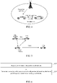
FIG. 1 is a block diagram of a Vehicle to Everything system according to an exemplary embodiment of the present application. -
FIG. 2 is a schematic diagram of a principle of listening to a Vehicle to Everything resource according to an exemplary embodiment of the present application. -
FIG. 3 is a schematic diagram of a sidelink feedback channel according to an exemplary embodiment of the present application. -
FIG. 4 is a schematic diagram of a power control method according to an exemplary embodiment of the present application. -
FIG. 5 is a schematic diagram of a scenario where a broadcast terminal interferes with a unicast terminal according to an exemplary embodiment of the present application. -
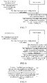
FIG. 6 is a flowchart of a power control method according to an exemplary embodiment of the present application. -
FIG. 7 is a flowchart of a power control method according to an exemplary embodiment of the present application. -
FIG. 8 is a flowchart of a power control method according to an exemplary embodiment of the present application. -
FIG. 9 is a flowchart of a power control method according to an exemplary embodiment of the present application. -
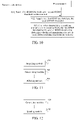
FIG. 10 is a flowchart of a method for determining a transmission resource according to an exemplary embodiment of the present application. -
FIG. 11 is a block diagram of a power control apparatus according to an exemplary embodiment of the present application. -
FIG. 12 is a block diagram of a power control apparatus according to an exemplary embodiment of the present application. -
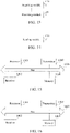
FIG. 13 is a block diagram of a power control apparatus according to an exemplary embodiment of the present application. -
FIG. 14 is a block diagram of an apparatus for determining a transmission resource according to an exemplary embodiment of the present application. -
FIG. 15 is a block diagram of a terminal according to an exemplary embodiment of the present application. -
FIG. 16 is a block diagram of a network side device according to an exemplary embodiment of the present application. - To make objects, the technical solutions, and advantages of the present application clearer, implementation modes of the present application will be described in further detail below with reference to the accompanying drawings.
- First, a brief description is made on several technical terms involved in the present application.
- Vehicle to Everything (V2X) is a Sidelink (SL) transmission technology based on D2D communication. Different from a conventional cellular system in which communication data is received or sent through a base station, a Vehicle to Everything system employs a mode of terminal-to-terminal direct communication, and therefore has a higher spectrum efficiency and a lower transmission delay. Two transmission modes are defined in the 3rd Generation Partnership Project (3GPP), i.e., mode A and mode B.
- In mode A, a transmission resource of a
terminal 120 is allocated by abase station 140 through a downlink, and theterminal 120 sends data on a sidelink according to the transmission resource allocated by thebase station 140; and thebase station 140 may allocate a transmission resource for single transmission to theterminal 120, and may also allocate a transmission resource for semi-static transmission to theterminal 120, as shown inFIG. 1 . - In mode B, a
terminal 120 selects one resource from a resource pool for data transmission. Specifically, theterminal 120 may select a transmission resource from the resource pool by means of listening, or select a transmission resource from the resource pool by means of random selection. - When a new data packet arrives at a point n in time and resource selection is required, a terminal will select a resource within [n+Tl, n+T2] milliseconds according to a listening result during past 1 second, wherein T1 <= 4 milliseconds; 20 milliseconds <= T2 <= 100 milliseconds, as shown in
FIG. 2 . - When the terminal selects a resource in a selection window, the terminal puts all resources in the resource selection window in a set A as candidate transmission resources, and performs exclusion on elements in the set A according to the listening result. A specific exclusion process is as follows.
- 1. If the terminal does not have a listening result for some subframes in a listening window, resources on subframes corresponding to these subframes in the selection window are excluded.
- 2. If the terminal detects a Physical Sidelink Control Channel (PSCCH) in the listening window, a Reference Signal Received Power (RSRP) of a Physical Sidelink Shared Channel (PSSCH) scheduled by the PSCCH is higher than a threshold, and a reserved transmission resource determined according to reservation information in control information has a resource conflict with data to be sent by a user, the user excludes the resource from the set A.
- 3. If a quantity of remaining resources in the set A is smaller than 20% of a total number of resources, the terminal will raise the threshold of the PSSCH-RSRP by 3dB and repeats acts land 2 until the quantity of remaining resources in the set A is greater than 20% of the total number of resources.
- 4. The terminal performs a Sidelink Received Signal Strength Indicator (S-RSSI) detection on the remaining resources in the set A, and sorts the remaining resources according to energy from high to low, and puts 20% (relative to a quantity of resources in the set A) of resources with a lowest energy into a set B.
- 5. The terminal selects a resource from the set B with equal probability for data transmission.
- In order to improve reliability, a sidelink feedback channel is introduced to V2X. For example, for unicast transmission, a sender terminal sends sidelink data (including a Physical Sidelink Control Channel (PSCCH) and a Physical Sidelink Shared Channel (PSSCH)) to a receiver terminal, the receiver terminal sends a Hybrid Automatic Repeat reQuest (HARQ) feedback information to the sender terminal, and the sender terminal determines whether retransmission is needed according to the feedback information of the receiver terminal. The HARQ feedback information is carried in a Physical Sidelink Feedback Channel (PSFCH), as shown in
FIG. 3 . - For the broadcast transmission mode, in order to allow more terminals to receive data, a sender terminal usually sends data using a maximum sending power. However, for the unicast or multicast transmission, a receiver terminal is one terminal or a group of terminals. Therefore, the sender terminal may adjust a sending power according to a status of a sidelink, so as to save energy and also reduce interference with other transmission links. In New Radio (NR)-V2X, a receiver terminal performs measurement according to a sidelink reference signal sent by a sender terminal, for example, an RSRP of a reference signal is measured, the RSRP is fed back to a sending side, a sidelink path loss is estimated at the sending side, and a sending power is adjusted according to the sidelink path loss. Or, a receiver terminal measures a sidelink reference signal, estimates a sidelink path loss, and feeds back the sidelink path loss to a sender terminal, and the sender terminal performs power control according to the sidelink path loss.
- Further, when a terminal is in a cell range, and when a same carrier is used for sidelink transmission and uplink transmission, in order to avoid interference from sidelink data transmission to uplink data transmission, the terminal needs to perform power control according to a downlink path loss, as shown in
FIG. 4 . The terminal performs measurement according to a downlink reference signal to obtain the downlink path loss, and determines a sending power according to the downlink path loss. - After introduction of power control, if a sending power of a terminal using the unicast transmission mode is reduced, listening processes of other terminals will be affected adversely. As shown in
FIG. 5 , UE1 and UE2 perform unicast communication, and UE3 is a broadcast user. When UE1 and UE2 perform unicast communication, power control is performed, and since UE1 and UE2 are very close to each other, a sending power of UE1 will be very low, e.g., 10dBm. When UE3 performs listening, since the sending power of UE1 is low, a PSSCH-RSRP of UE1 measured by UE3 is very low, and UE3 will consider that interference on a transmission resource used by UE1 is very low, and therefore will believe that the transmission resource is an available resource. If UE3 selects the transmission resource and performs broadcast transmission, in order to ensure that data of UE3 can be received by more users, such as UE4, UE3 usually uses a maximum power (e.g., 23dBm) for sending, so a signal of UE3 interferes with receiving of UE2, resulting in UE2's failure to receive data of UE1. - The above terminals may include various handheld devices, vehicle-mounted devices, wearable devices, computing devices with wireless communication functions, or other processing devices connected to a wireless modem, and various types of User Equipment (UEs), Mobile Stations (MSs), terminal devices, and the like. For convenience of description, the above-mentioned devices are collectively referred to as terminals or UEs.
-
FIG. 6 is a flowchart of a power control method according to an exemplary embodiment of the present application. In this embodiment, description is made by taking a case where the method is performed by a first terminal as an example. The method includes act 601 and act 602. - In act 601, power control configuration information is acquired.
- Optionally, the first terminal acquires preconfigured power control configuration information. Or, the first terminal receives power control configuration information sent by a network side device. Or, the first terminal receives power control configuration information sent by a second terminal.
- Optionally, the power control configuration information is carried in resource pool (or sidelink transmission resource pool, D2D resource pool or V2X resource pool) configuration information and the power control configuration information is used for indicating whether to perform power control on transmission resources in the resource pool. Optionally, the transmission resources in the resource pool are used for transmission of at least two types of data among unicast sidelink data, multicast sidelink data, and broadcast sidelink data. Optionally, the transmission resources in the resource pool are for selection and use by multiple terminals after listening. The multiple terminals include terminals using the unicast transmission mode, terminals using the multicast transmission mode, and terminals using the broadcast transmission mode.
- In
act 602, whether to perform power control when sidelink data is sent is determined according to the power control configuration information. - Exemplarily, the "power control" includes at least one of the following three forms: 1. whether to perform power control according to a sidelink path loss when sidelink data is sent is determined according to the power control configuration information; 2. whether to perform power control according to a downlink path loss when sidelink data is sent is determined according to the power control configuration information; and 3. whether to perform power control on a PSCCH when sidelink data is sent is determined according to the power control configuration information.
- To sum up, in the method according to this embodiment, power control configuration information is used for indicating that a first terminal does not need to perform power control, so that a terminal using a resource pool (or resources) does not need to perform power control (i.e., neither performs power control according to a sidelink path loss, nor performs power control according to a downlink path loss) when sending sidelink data, and the first terminal may send sidelink data using a maximum sending power. Therefore, all terminals using a same resource pool do not perform power control, thus avoiding a problem that when a terminal adopting a unicast transmission mode performs power control on a resource, a terminal adopting a broadcast transmission mode determines, when listening, that the resource is available and thus preempts the resource, causing a transmission conflict.
-
FIG. 7 is a flowchart of a power control method according to another exemplary embodiment of the present application. In this embodiment, description is made by taking a case where the method is performed by a first terminal and a network side device (or a second terminal) as an example. The method includesacts 701 to 704. - In
act 701, a network side device generates power control configuration information. - The network side device may be an access network device, such as a base station.
- In an example, when generating resource pool configuration information, the network side device generates power control configuration information corresponding to the resource pool (or sidelink transmission resource pool or D2D resource pool or V2X resource pool).
- In an example, when dynamically scheduling sidelink transmission, the network side device generates power control configuration information corresponding to a dynamically scheduled resource (or sidelink transmission resource or D2D resource or V2X resource).
- In an example, when semi-statically scheduling sidelink transmission, the network side device generates power control configuration information corresponding to a semi-statically scheduled resource (or sidelink transmission resource or D2D resource or V2X resource).
- In an example, when configuring a sidelink transmission resource through sidelink configuration grant, the network side device generates power control configuration information corresponding to a resource of sidelink configuration grant (or sidelink transmission resource or D2D resource or V2X resource).
- In act 702, the network side device sends the power control configuration information.
- In an example, the network side device sends broadcast information, and resource pool configuration information is carried in the broadcast information, and power control configuration information is carried in the resource pool configuration information.
- In an example, the network side device sends a first Radio Resource Control (RRC) specific signaling, and resource pool configuration information is carried in the first RRC specific signaling, and power control configuration information is carried in the resource pool configuration information. An RRC specific signaling refers to an RRC signaling which usually may be scrambled using a Cell Radio-Network Temporary Identifier (C-RNTI) of the terminal and is sent by the network side device specifically to a current terminal.
- In an example, the network side device sends first Downlink Control Information (DCI), and power control configuration information is carried in the first DCI.
- The first DCI is used for dynamically allocating a sidelink transmission resource for a first terminal.
- In an example, the network side device sends a second RRC specific signaling, and the second RRC specific signaling is used for configuring sidelink configuration grant, and power control configuration information is carried in the second RRC specific signaling.
- For example, the SideLink Configuration Grant is a Type-1 Configuration Grant (Type-1 CG).
- In an example, the network side device sends a second RRC specific signaling and second DCI, and the second RRC specific signaling is used for configuring sidelink configuration grant, and the second DCI is used for activating or deactivating the sidelink configuration grant, and power control configuration information is carried in the second RRC specific signaling or the second DCI.
- For example, the SideLink Configuration Grant is a Type-2 Configuration Grant (Type-2 CG). A transmission resource configured using the Type-2 CG can only be used after being activated using the second DCI.
- In act 703, a first terminal receives the power control configuration information.
- In an example, the first terminal receives broadcast information sent by the network side device, and resource pool configuration information is carried in the broadcast information, and power control configuration information is carried in the resource pool configuration information.
- In an example, the first terminal receives a first RRC specific signaling sent by the network side device, and resource pool configuration information is carried in the first RRC specific signaling, and power control configuration information is carried in the resource pool configuration information.
- In an example, the first terminal receives first DCI sent by the network side device, and power control configuration information is carried in the first DCI.
- In an example, the first terminal receives a second RRC specific signaling sent by the network side device, and the second RRC specific signaling is used for configuring sidelink configuration grant, and power control configuration information is carried in the second RRC specific signaling.
- In an example, the first terminal receives a second RRC specific signaling and second DCI sent by the network side device, the second DCI is used for activating or deactivating sidelink configuration grant, and power control configuration information is carried in the second RRC specific signaling or the second DCI.
- In act 704, the first terminal determines, according to the power control configuration information, whether to perform power control when sending sidelink data.
- Exemplarily, the "power control" includes at least one of the following three forms: 1. whether to perform power control according to a sidelink path loss when sidelink data is sent is determined according to the power control configuration information; 2. whether to perform power control according to a downlink path loss when sidelink data is sent is determined according to the power control configuration information; and 3. whether to perform power control on a PSCCH when sidelink data is sent is determined according to the power control configuration information.
- To sum up, in the method according to this embodiment, power control configuration information is used for indicating that a first terminal does not need to perform power control, so that a terminal using a resource pool (or resources) does not need to perform power control (i.e., neither performs power control according to a sidelink path loss, nor performs power control according to a downlink path loss) when sending sidelink data, and the first terminal may send sidelink data using a maximum sending power. Therefore, all terminals using a same resource pool do not perform power control, thus avoiding a problem that when a terminal adopting a unicast transmission mode performs power control on a resource, a terminal adopting a broadcast transmission mode determines, when listening, that the resource is available and thus preempts the resource, causing a transmission conflict.
- Further, in the present application, the power control configuration information is carried in a RRC specific signaling or DCI, and for a scenario where the terminal independently selects a resource in a resource pool, a scenario of semi-static scheduling, a scenario of dynamic scheduling, etc., a power control function may be enabled or disabled, so that in the three transmission scenarios, all terminals using a same resource pool may not perform power control, thus avoiding a problem that when a terminal adopting a unicast transmission mode performs power control on a resource, a terminal adopting a broadcast transmission mode determines, when listening, that the resource is available and thus preempts the resource, causing a transmission conflict.
- It should be noted that the above power control configuration information may also be generated and sent by a second terminal.
- The second terminal may be a group head terminal of a communication group where the first terminal is located. The group head terminal is a terminal that has at least one of functions of resource management, resource allocation, resource coordination, and group management within a communication group.
- For example, the first terminal, the second terminal and a third terminal constitute a communication group, wherein the second terminal is a group head terminal of the group, and the second terminal may send first configuration information to the first terminal to indicate whether the first terminal needs to perform power control.
- The second terminal may also be an opposite terminal (relative to the first terminal) in unicast communication.
- For example, the first terminal and the second terminal perform unicast communication, and the first terminal may receive the first configuration information sent by the second terminal, and determine, according to the first configuration information, whether to perform power control.
- Optionally, the first configuration information may be carried through a PSCCH or a sidelink RRC signaling.
- In optional embodiments based on
FIG. 6 andFIG. 7 , act 705 is further included after the act 704, as shown inFIG. 8 . - In act 705, the first terminal determines a magnitude of a sidelink path loss, in a case of determining to perform power control according to the sidelink path loss.
- Exemplarily, the first terminal determines the magnitude of the sidelink path loss according to a sending power and an RSRP measurement result.
- A determining process with respect to the sending power is as follows.
- The first terminal determines the sending power according to a first sending power of a PSSCH sent by the first terminal. In an example, the first sending power is a sending power on each Resource Element (RE) of a PSSCH sent by the first terminal.
- The first terminal may use a single antenna port for sending, or use multiple antenna ports for sending. When the first terminal uses a single antenna port for sending, the first sending power is a sending power of each RE on the single antenna port. When the first terminal uses N antenna ports for sending, N being an integer greater than 1, the first sending power is a sum of sending powers of each RE on N antenna ports. Taking N being equal to 2 as an example, the first sending power is a sum of sending powers of each RE on two antenna ports. In an example, serial numbers of REs sending a PSSCH on two antenna ports are


- Optionally, the PSSCH is a PSSCH already sent on the first terminal. When the first terminal calculates a sidelink path loss, a sending power of the PSSCH needs to be used, and since the PSSCH is a PSSCH already sent by the first terminal, the sending power of the PSSCH may be determined according to a sending power used by the first terminal when sending the PSSCH.
- In another possible implementation mode, when the first terminal uses N antenna ports for sending, N being an integer greater than 1, the first sending power is N times that of a first antenna port among the N antenna ports. The first antenna port is any one of the N antenna ports, or the first antenna port is a designated one of the N antenna ports.
- A determining process with respect to an RSRP measurement result is as follows.
- The RSRP measurement result is obtained through measurement according to a Physical SideLink Shared Channel Demodulation Reference Signal (PSSCH DMRS) and/or a Physical SideLink Control Channel Demodulation Reference Signal (PSCCH DMRS) sent by the first terminal.
- Exemplarily, the first terminal receives an RSRP measurement result sent by the second terminal, and the RSRP measurement result is obtained through measurement by the second terminal according to a PSSCH DMRS or a PSCCH DMRS sent by the first terminal. After obtaining the RSRP measurement result through measurement by the second terminal according to the PSSCH DMRS or the PSCCH DMRS sent by the first terminal, the second terminal sends the RSRP measurement result to the first terminal.
- The first terminal may use a single antenna port for sending, or use multiple antenna ports for sending. When the first terminal uses a single antenna port for sending, the RSRP measurement result is an RSRP measurement result of the single antenna port. When the first terminal uses M antenna ports for sending, M being an integer greater than 1, the RSRP measurement result is a sum of RSRP measurement results of M antenna ports. Take M being equal to 2 as an example, the RSRP measurement result is a sum of RSRP measurement results on two antenna ports.
- In another possible implementation mode, when the first terminal uses M antenna ports for sending, M being an integer greater than 1, the RSRP measurement result is M times that of a first antenna port among the M antenna ports. The first antenna port is any one of the M antenna ports, or the first antenna port is a designated one of the M antenna ports.
- In an optional embodiment based on
FIG. 8 , act 705 includesact 7051 andact 7052, as shown inFIG. 9 . - In
act 7051, a first filtering processing is performed on a sending power, and a second filtering processing is performed on a Reference Signal Received Power (RSRP) measurement result. - Optionally, the second terminal performs RSRP measurement according to a PSSCH DMRS sent by the first terminal, performs a second filtering processing on an RSRP measurement result, and feeds back the RSRP measurement result after the second filtering processing to the first terminal.
- Optionally, the first terminal sends a PSSCH, performs a first filtering processing on a sending power on an RE carrying a PSSCH DMRS, and calculates a sidelink path loss according to the sending power after the first filtering processing.
- Optionally, a same filtering coefficient is used for the first filtering processing and the second filtering processing.
- In
act 7052, a magnitude of a sidelink path loss is determined according to the sending power and the RSRP measurement result. - In an example, the first terminal calculates the magnitude of the sidelink path loss according to the following formula.

- In the above formula, referenceSignalPower is obtained according to a PSSCH transmission power of each RE of the first terminal. Optionally, this parameter is obtained by performing higher-layer filtering on a PSSCH transmission opportunity using a first filtering coefficient. Exemplarily, the referenceSignalPower is calculated for an RE of each reference signal. When the first terminal sends a PSSCH, an RE carrying data and an RE carrying a DMRS have a same power. Therefore, for a single antenna port, a power on each RE is calculated (or a power on each DMRS RE is calculated), which is the referenceSignalPower. Optionally, the first terminal may divide the sending power by a quantity of REs occupied by a PSSCH channel on each Orthogonal Frequency-Division Multiplexing (OFDM) symbol, thus determining a sending power on each RE, i.e., a power on each PSSCH DMRS RE.
- Higher layer filtered RSRP is an RSRP after higher-layer filtering, and the RSRP is obtained through measurement according to a PSSCH DMRS or a PSCCH DMRS. This parameter is reported to the first terminal from the second terminal receiving PSCCH/PSSCH transmission. Optionally, the second terminal uses a first filter coefficient to perform higher-layer filtering on an RSRP measurement and reports a filtered RSRP to the first terminal.
- That is, the sending power and the RSRP measurement result are obtained by performing higher-layer filtering according to a same filter configuration.
- To sum up, in the method according to this embodiment, by determining the magnitude of the sidelink path loss by the first terminal, power control may be reasonably performed when sidelink data is sent, communication interference may be reduced and communication efficiency may be improved.
- In the method according to this embodiment, for each RE, powers of multiple antenna ports are added to calculate a total power of the RE, and a sidelink path loss is calculated according to the total power, which improves calculation accuracy of the sidelink path loss.
-
FIG. 10 is a flowchart of a method for determining a transmission resource according to an exemplary embodiment of the present application. In this embodiment, description is made by taking a case where the method is performed by a terminal and a network side device as an example. The method includesact 801 to act 803. - In
act 801, a network side device sends a first RSRP threshold and a second RSRP threshold to a terminal. - Optionally, the first RSRP threshold is smaller than the second RSRP threshold.
- Optionally, the network side device sends the first RSRP threshold and the second RSRP threshold to the terminal through a downlink.
- In
act 802, the terminal acquires the first RSRP threshold and the second RSRP threshold. - In act 803, when determining a candidate transmission resource for Device to Device (D2D), the terminal uses the first RSRP threshold or the second RSRP threshold to determine whether a transmission resource is an available candidate transmission resource.
- Optionally, if sidelink data transmitted on the candidate transmission resource is transmitted in unicast, and/or supports power control, the terminal uses the first RSRP threshold to determine whether the transmission resource is an available candidate transmission resource. Otherwise, the second RSRP threshold is used for determining whether the transmission resource is an available candidate transmission resource.
- For example, in a scenario where sidelink data is transmitted in unicast or supports power control, if the terminal detects scheduling information on a PSCCH when performing resource listening, it will measure a PSSCH-RSRP on a transmission resource of a PSSCH scheduled through the scheduling information and compare the PSSCH-RSRP with the first RSRP threshold. If the measured PSSCH-RSRP is lower than the first RSRP threshold, the transmission resource is considered to be an available candidate transmission resource; and if the measured PSSCH-RSRP is higher than the first RSRP threshold, the transmission resource is considered to be unavailable and is excluded from candidate transmission resources.
- In another example, in a scenario where sidelink data uses multicast transmission, broadcast transmission, or does not support power control, if the terminal detects scheduling information on a PSCCH when performing resource listening, it will measure a PSSCH-RSRP on a transmission resource of a PSSCH scheduled through the scheduling information and compare the PSSCH-RSRP with the second RSRP threshold. If the measured PSSCH-RSRP is lower than the second RSRP threshold, the transmission resource is considered to be an available candidate transmission resource; and if the measured PSSCH-RSRP is higher than the second RSRP threshold, the transmission resource is considered to be unavailable and is excluded from candidate transmission resources.
- Optionally, the terminal may determine, through indication information carried in a PSCCH, which of unicast, multicast, and broadcast is a transmission mode used for current sidelink data. Specifically, any of following implementation modes may be included.
- 1. Indication information is carried in SideLink Control Information (SCI) for distinguishing transmission types.
- 2. Destination identification information is carried in SCI for distinguishing transmission types.
- To sum up, in the method according to this embodiment, by configuring a first RSRP threshold and a second RSRP threshold which are different, the terminal may configure, when listening to a resource, a lower RSRP threshold for unicast transmission or transmission that supports power control, so that when listening to a resource, the terminal may avoid preempting a transmission resource of unicast transmission, thereby avoiding interfering with unicast transmission.
- In an optional embodiment based on
FIG. 10 , the first RSRP threshold is for use by a terminal when sidelink data transmitted on a candidate transmission resource is transmitted in unicast. That is, if the sidelink data transmitted on the candidate transmission resource is transmitted in unicast, the terminal uses the first RSRP threshold to determine whether a transmission resource is an available candidate transmission resource; otherwise, the terminal uses the second RSRP threshold to determine whether a transmission resource is an available candidate transmission resource. - In an optional embodiment based on
FIG. 10 , the first RSRP threshold is for use by a terminal when power control is performed on sidelink data transmitted on a candidate transmission resource. That is, if power control is performed on the sidelink data transmitted on the candidate transmission resource, the terminal uses the first RSRP threshold to determine whether a transmission resource is an available candidate transmission resource; otherwise, the terminal uses the second RSRP threshold to determine whether a transmission resource is an available candidate transmission resource. - In an optional embodiment based on
FIG. 10 , the first RSRP threshold is for use by a terminal when sidelink data transmitted on a candidate transmission resource is transmitted in unicast and a priority is higher than a priority threshold. That is, if the sidelink data transmitted on the candidate transmission resource is transmitted in unicast and the priority is higher than the priority threshold, the terminal uses the first RSRP threshold to determine whether a transmission resource is an available candidate transmission resource; otherwise, the terminal uses the second RSRP threshold to determine whether a transmission resource is an available candidate transmission resource. - The priority is a first priority carried in a sidelink control channel corresponding to the sidelink data or a second priority corresponding to the sidelink data to be transmitted. The priority threshold may be configured by a network side device, or may be preconfigured or predefined. It should be understood that a higher level of the priority carried in the sidelink control channel indicates a lower priority of corresponding sidelink data; and a lower level of the priority indicates a higher priority of corresponding sidelink data.
- In an optional embodiment based on
FIG. 10 , the first RSRP threshold is for use by a terminal when power control is performed on sidelink data transmitted on a candidate transmission resource and a priority is higher than a priority threshold. That is, if power control is performed on the sidelink data transmitted on the candidate transmission resource and the priority is higher than the priority threshold, the terminal uses the first RSRP threshold to determine whether a transmission resource is an available candidate transmission resource; otherwise, the terminal uses the second RSRP threshold to determine whether a transmission resource is an available candidate transmission resource. - The priority is a first priority carried in a sidelink control channel corresponding to the sidelink data or a second priority corresponding to the sidelink data to be transmitted. The priority threshold may be configured by a network side device, or may be preconfigured or predefined.
- It should be noted that in the above examples, the number of the first RSRP thresholds and the number of the second RSRP thresholds are both one for illustration.
- In another example, there are at least two first RSRP thresholds, and each first RSRP threshold corresponds to a different priority pair, i.e., different priority pairs may correspond to multiple first RSRP thresholds which may be the same or different. When listening to a resource, the first terminal determines a currently used first RSRP among at least two first RSRP thresholds according to a first priority pair. That is, a first RSRP threshold is determined according to a first priority pair.
- In another example, there are at least two second RSRP thresholds, and each second RSRP threshold corresponds to a different priority pair, i.e., different priority pairs may correspond to multiple second RSRP thresholds which may be the same or different. When listening to a resource, the first terminal determines a currently used second RSRP among at least two second RSRP thresholds according to a second priority pair. That is, a second RSRP threshold is determined according to a second priority pair.
- A priority pair (e.g., a first priority pair or a second priority pair) includes a first priority and a second priority, the first priority is a priority carried in a sidelink control channel, and the second priority is a priority corresponding to sidelink data to be transmitted.
- It should be noted that the acts performed by a single terminal in the above embodiment may be independently implemented as a power control method of a terminal side, and the acts performed by the network side device in the above embodiment may be independently implemented as a power control method of the network side device.
-
FIG. 11 is a block diagram of a power control apparatus according to an exemplary embodiment of the present application. The apparatus may be implemented as a part of a first terminal. The apparatus includes an acquiringmodule 920 and a determiningmodule 940. - The acquiring
module 920 is configured to acquire power control configuration information. - The determining
module 940 is configured to determine, according to the power control configuration information, whether to perform power control when sidelink data is sent. - In an optional embodiment, the acquiring
module 920 is configured to acquire preconfigured power control configuration information; or the acquiringmodule 920 is configured to receive the power control configuration information sent by a network side device; or the acquiringmodule 920 is configured to receive the power control configuration information sent by a second terminal. - In an optional embodiment, the acquiring
module 920 is configured to receive broadcast information sent by a network side device, resource pool configuration information is carried in the broadcast information, and the power control configuration information is carried in the resource pool configuration information; or, the acquiringmodule 920 is configured to receive a first Radio Resource Control (RRC) specific signaling sent by a network side device, resource pool configuration information is carried in the first RRC specific signaling and the power control configuration information is carried in the resource pool configuration information; or the acquiringmodule 920 is configured to receive first Downlink Control Information (DCI) sent by a network side device, the power control configuration information is carried in the first DCI. - In an optional embodiment, the acquiring
module 920 is configured to receive a second RRC specific signaling sent by a network side device, the second RRC specific signaling being used for configuring sidelink configuration grant, and the power control configuration information is carried in the second RRC specific signaling; or the acquiringmodule 920 is configured to receive the second RRC specific signaling and second DCI sent by the network side device, the second DCI being used for activating or deactivating the sidelink configuration grant, and the power control configuration information is carried in the second RRC specific signaling or the second DCI. - In an optional embodiment, the second terminal is a group head terminal of a communication group where the first terminal is located; or the second terminal is an opposite terminal in unicast communication.
- In an optional embodiment, the power control configuration information is carried in a Sidelink Control Channel (PSCCH) or a sidelink RRC signaling.
- In an optional embodiment, the determining
module 940 is configured to determine, according to the power control configuration information, whether to perform power control according to a sidelink path loss when the sidelink data is sent; and/or, the determiningmodule 940 is configured to determine, according to the power control configuration information, whether to perform power control according to a downlink path loss when the sidelink data is sent; and/or, the determiningmodule 940 is configured to determine, according to the power control configuration information, whether to perform power control on a Sidelink Control Channel (PSCCH) when the sidelink data is sent. - In an optional embodiment, the determining
module 940 is further configured to determine a magnitude of the sidelink path loss in a case of performing power control according to the sidelink path loss. - In an optional embodiment, the determining
module 940 is further configured to determine a magnitude of the sidelink path loss according to a sending power and a Reference Signal Received Power (RSRP) measurement result. - In an optional embodiment, the determining
module 940 is further configured to determine the sending power according to a first sending power of a PSSCH transmitted by the apparatus. - In an optional embodiment, the first sending power includes a sending power on each resource element of the PSSCH transmitted by the apparatus.
- In an optional embodiment, the apparatus uses a single antenna port for sending, and the first sending power is a sending power of the single antenna port.
- In an optional embodiment, the apparatus uses N antenna ports for sending, N being an integer greater than 1; and the first sending power is a sum of sending powers of the N antenna ports. Or, the first sending power is N times a sending power of a first antenna port among the N antenna ports, and the first antenna port is any one of the N antenna ports.
- In an optional embodiment, the RSRP measurement result is obtained through measurement according to a PSSCH DMRS and/or a PSCCH DMRS sent by the first terminal.
- In an optional embodiment, the acquiring
module 920 is further configured to receive the RSRP measurement result sent by the second terminal, and the RSRP measurement result is obtained through measurement by the second terminal device according to the PSSCH DMRS or the PSCCH DMRS sent by the apparatus. - In an optional embodiment, the apparatus uses a single antenna port for sending, and the RSRP measurement result is an RSRP measurement result of the single antenna port.
- In an optional embodiment, the apparatus uses M antenna ports for sending, M being an integer greater than 1; the RSRP measurement result is a sum of RSRP measurement results of the M antenna ports. Or, the RSRP measurement result is M times an RSRP measurement result of a first antenna port among the M antenna ports.
- In an optional embodiment, the apparatus further includes a
filtering module 960. - The
filtering module 960 is configured to perform a first filtering processing on the sending power and a second filtering processing on the RSRP measurement result. - In an optional embodiment, the
filtering module 960 is further configured to use a same filtering coefficient to perform the first filtering processing and the second filtering processing. -
FIG. 12 is a block diagram of a power control apparatus according to an exemplary embodiment of the present application. The apparatus may be implemented as a part of a network side device or a second device. The apparatus includes agenerating module 1020 and asending module 1040. - The
generating module 1020 is configured to generate power control configuration information, the power control configuration information being used for indicating whether a first terminal performs power control when sidelink data is sent. - The sending
module 1040 is configured to send the power control configuration information. - In an optional embodiment, the apparatus is applied to a network side device, the sending
module 1040 is configured to send broadcast information, resource pool configuration information is carried in the broadcast information, and the power control configuration information is carried in the resource pool configuration information; or the sendingmodule 1040 is configured to send a first Radio Resource Control (RRC) specific signaling, resource pool configuration information is carried in the first RRC specific signaling, and the power control configuration information is carried in the resource pool configuration information; or the sendingmodule 1040 is configured to send first Downlink Control Information (DCI), the power control configuration information is carried in the first DCI. - In an optional embodiment, the apparatus is applied to a network side device, the sending
module 1040 is configured to send a second RRC specific signaling, the second RRC specific signaling being used for configuring sidelink configuration grant, and the power control configuration information is carried in the second RRC specific signaling; or the sendingmodule 1040 is configured to send the second RRC specific signaling and second DCI, the second DCI being used for activating or deactivating the sidelink configuration grant, and the power control configuration information is carried in the second RRC specific signaling or the second DCI. - In an optional embodiment, the apparatus is applied to a second device; the second terminal is a group head terminal of a communication group where the first terminal is located; or the second terminal is an opposite terminal in unicast communication.
- In an optional embodiment, the power control configuration information is carried in a Sidelink Control Channel (PSCCH) or a sidelink RRC signaling.
- In an optional embodiment, the power control configuration information is used for indicating whether the first terminal performs power control according to a sidelink path loss when the sidelink data is sent; and/or the power control configuration information is used for indicating whether the first terminal performs power control according to a downlink path loss when the sidelink data is sent; and/or the power control configuration information is used for indicating whether the first terminal performs power control on a Sidelink Control Channel (PSCCH) when the sidelink data is sent.
-
FIG. 13 is a block diagram of an apparatus for determining a transmission resource according to an exemplary embodiment of the present application. The apparatus may be implemented as a part of a first terminal, and the apparatus includes an acquiringmodule 1120 and aprocessing module 1140. - The acquiring
module 1120 is configured to acquire a first Reference Signal Received Power (RSRP) threshold and a second RSRP threshold. - The
processing module 1140 is configured to use, when determining a candidate transmission resource for D2D, the first RSRP threshold or the second RSRP threshold to determine whether the transmission resource is an available candidate transmission resource. - In an optional embodiment, the
processing module 1140 is configured to use the first RSRP threshold to determine whether the transmission resource is an available candidate transmission resource if sidelink data transmitted on a candidate transmission resource is transmitted in unicast; otherwise, use the second RSRP threshold to determine whether the transmission resource is an available candidate transmission resource; or theprocessing module 1140 is configured to use the first RSRP threshold to determine whether the transmission resource is an available candidate transmission resource if power control is performed on sidelink data transmitted on a candidate transmission resource; otherwise, use the second RSRP threshold to determine whether the transmission resource is an available candidate transmission resource. - In an optional embodiment, the
processing module 1140 is configured to use the first RSRP threshold to determine whether the transmission resource is an available candidate transmission resource if sidelink data transmitted on a candidate transmission resource is transmitted in unicast and a priority is higher than a priority threshold; otherwise, use the second RSRP threshold to determine whether the transmission resource is an available candidate transmission resource; or theprocessing module 1140 is configured to use the first RSRP threshold to determine whether the transmission resource is an available candidate transmission resource if power control is performed on sidelink data transmitted on a candidate transmission resource and a priority is higher than the priority threshold; otherwise, use the second RSRP threshold to determine whether the transmission resource is an available candidate transmission resource. - The priority is a first priority carried in a sidelink control channel corresponding to the sidelink data or a second priority corresponding to the sidelink data to be transmitted.
- In an optional embodiment, the first RSRP threshold is determined according to a first priority pair, and the second RSRP threshold is determined according to a second priority pair; wherein the first priority pair or the second priority pair includes a first priority and a second priority, the first priority is a priority carried in a sidelink control channel, and the second priority is a priority corresponding to sidelink data to be transmitted.
-
FIG. 14 is a block diagram of an apparatus for determining a transmission resource according to an exemplary embodiment of the present application. The apparatus may be implemented as a part of a network side device. The apparatus includes asending module 1220. - The sending
module 1220 is configured to send a first Reference Signal Received Power (RSRP) threshold and a second RSRP threshold to a terminal, the terminal being configured to use, when determining a candidate transmission resource for D2D, the first RSRP threshold or the second RSRP threshold to determine whether the transmission resource is an available candidate transmission resource. - In an optional embodiment, the first RSRP threshold is for use by the terminal when sidelink data transmitted on a candidate transmission resource is transmitted in unicast; or the first RSRP threshold is for use by the terminal when power control is performed on sidelink data transmitted on a candidate transmission resource.
- In an optional embodiment, the first RSRP threshold is for use by the terminal when sidelink data transmitted on a candidate transmission resource is transmitted in unicast and a priority is higher than a priority threshold; or the first RSRP threshold is for use by the terminal when power control is performed on sidelink data transmitted on a candidate transmission resource and a priority is higher than the priority threshold; wherein the priority is a first priority carried in a sidelink control channel corresponding to the sidelink data or a second priority corresponding to the sidelink data to be transmitted.
- In an optional embodiment, there are at least two first RSRP thresholds, and each first RSRP threshold corresponds to a different priority pair; and/or there are at least two second RSRP thresholds, and each second RSRP threshold corresponds to a different priority pair; wherein the priority pair includes a first priority and a second priority, the first priority is a priority carried in a sidelink control channel, and the second priority is a priority corresponding to sidelink data to be transmitted.
-
FIG. 15 is a schematic diagram of a structure of a terminal according to an exemplary embodiment of the present application. The terminal includes aprocessor 1301, areceiver 1302, atransmitter 1303, amemory 1304, and abus 1305. - The
processor 1301 includes one or more processing cores. Theprocessor 1301 performs various functional applications and information processing by running software programs and modules. - The
receiver 1302 and thetransmitter 1303 may be implemented as a communication assembly, which may be a communication chip. - The
memory 1304 is connected to theprocessor 1301 via thebus 1305. - The
memory 1304 may be configured to store at least one instruction, and theprocessor 1301 is configured to execute the at least one instruction to implement various acts in the above method embodiments. - In addition, the
memory 1304 may be implemented by any type of transitory or non-transitory storage device or a combination thereof. The transitory or non-transitory storage device includes, but is not limited to, a magnetic disk or an optical disk, an Electrically Erasable Programmable Read Only Memory (EEPROM), an Erasable Programmable Read Only Memory (EPROM), a Static Random Access Memory (SRAM), a Read Only Memory (ROM), a magnetic memory, a flash memory, and a Programmable Read Only Memory (PROM). - In an exemplary embodiment, a computer-readable storage medium is also provided, which stores at least one instruction, at least one program, a code set, or an instruction set, the at least one instruction, the at least one program, the code set, or the instruction set being loaded and executed by the processor to implement the power control method or the method for determining a transmission resource performed by a terminal according to the above various method embodiments.
-
FIG. 16 is a schematic diagram of a structure of a network side device according to an exemplary embodiment of the present application. The network side device includes aprocessor 1401, areceiver 1402, atransmitter 1403, amemory 1404, and abus 1405. - The
processor 1401 includes one or more processing cores. Theprocessor 1401 performs various functional applications and information processing by running software programs and modules. - The
receiver 1402 and thetransmitter 1403 may be implemented as a communication assembly, which may be a communication chip. - The
memory 1404 is connected to theprocessor 1401 via thebus 1405. - The
memory 1404 may be configured to store at least one instruction, and theprocessor 1401 is configured to execute the at least one instruction to implement various acts in the above method embodiments. - In addition, the
memory 1404 may be implemented by any type of transitory or non-transitory storage device or a combination thereof. The transitory or non-transitory storage device includes, but is not limited to, a magnetic disk or an optical disk, an Electrically Erasable Programmable Read Only Memory (EEPROM), an Erasable Programmable Read Only Memory (EPROM), a Static Random Access Memory (SRAM), a Read Only Memory (ROM), a magnetic memory, a flash memory, and a Programmable Read Only Memory (PROM). - In an exemplary embodiment, a computer-readable storage medium is also provided, which stores at least one instruction, at least one program, a code set, or an instruction set, the at least one instruction, the at least one program, the code set, or the instruction set being loaded and executed by the processor to implement the power control method or the method for determining a transmission resource performed by a network side device according to the above various method embodiments.
- One of ordinary skills in the art may understand that all or part of the acts for implementing the embodiments may be completed through hardware, or may be completed by instructing related hardware through programs, the programs may be stored in a computer-readable storage medium, the above-mentioned storage medium may be a read only memory, a magnetic disk, or an optical disk, etc.
- The above are only optional embodiments of the present application, which are not intended to limit the present application. Any modification, equivalent substitution, improvement, etc., made within the spirit and principles of the present application shall be included in the protection scope of the present application.
Claims (69)
- A power control method, applied to a first terminal, the method comprising:acquiring power control configuration information; anddetermining, according to the power control configuration information, whether to perform power control when sending sidelink data.
- The method according to claim 1, wherein the acquiring the power control configuration information comprises:acquiring the power control configuration information that is preconfigured;or,receiving the power control configuration information sent by a network side device;or,receiving the power control configuration information sent by a second terminal.
- The method according to claim 2, wherein the receiving the power control configuration information sent by the network side device comprises:receiving broadcast information sent by the network side device, resource pool configuration information being carried in the broadcast information, and the power control configuration information being carried in the resource pool configuration information;or,receiving a first Radio Resource Control (RRC) specific signaling sent by the network side device, resource pool configuration information being carried in the first RRC specific signaling, and the power control configuration information being carried in the resource pool configuration information;or,receiving first Downlink Control Information (DCI) sent by the network side device, the power control configuration information being carried in the first DCI.
- The method according to claim 2, wherein the receiving the power control configuration information sent by the network side device comprises:receiving a second Radio Resource Control (RRC) specific signaling sent by the network side device, the second RRC specific signaling being used for configuring sidelink configuration grant, and the power control configuration information being carried in the second RRC specific signaling;or,receiving the second RRC specific signaling and second Downlink Control Information (DCI) sent by the network side device, the second DCI being used for activating or deactivating the sidelink configuration grant, and the power control configuration information being carried in the second RRC specific signaling or the second DCI.
- The method according to claim 2, whereinthe second terminal is a group head terminal of a communication group where the first terminal is located;or,the second terminal is an opposite terminal in unicast communication.
- The method according to claim 5, wherein
the power control configuration information is carried in a Physical Sidelink Control Channel (PSCCH) or a sidelink Radio Resource Control (RRC) signaling. - The method according to any one of claims 1 to 6, wherein the determining, according to the power control configuration information, whether to perform power control when sending sidelink data comprises:determining, according to the power control configuration information, whether to perform power control according to a sidelink path loss when sending the sidelink data;and/or,determining, according to the power control configuration information, whether to perform power control according to a downlink path loss when sending the sidelink data;and/or,determining, according to the power control configuration information, whether to perform power control on a Physical Sidelink Control Channel (PSCCH) when sending the sidelink data.
- The method according to claim 7, wherein in a case of determining to perform power control according to the sidelink path loss, the method further comprises:
determining a magnitude of the sidelink path loss. - The method according to claim 8, wherein the determining the magnitude of the sidelink path loss comprises:
determining the magnitude of the sidelink path loss according to a sending power and a Reference Signal Received Power (RSRP) measurement result. - The method according to claim 9, wherein the method further comprises:
determining the sending power according to a first sending power of a Physical Sidelink Shared Channel (PSSCH) sent by the first terminal. - The method according to claim 10, wherein the first sending power is a sending power on each resource element of the PSSCH sent by the first terminal.
- The method according to any one of claims 9 to 11, wherein the first terminal uses a single antenna port for sending;
the first sending power is a sending power of the single antenna port. - The method according to any one of claims 9 to 11, wherein the first terminal uses N antenna ports for sending, N being an integer greater than 1;
the first sending power is a sum of sending powers of the N antenna ports. - The method according to claim 9, wherein the Reference Signal Received Power (RSRP) measurement result is obtained through measurement according to a Physical SideLink Shared Channel Demodulation Reference Signal (PSSCH DMRS) and/or a Physical SideLink Control Channel Demodulation Reference Signal (PSCCH DMRS) sent by the first terminal.
- The method according to claim 14, wherein the method further comprises:
receiving, by the first terminal, the RSRP measurement result sent by the second terminal, the RSRP measurement result being obtained through measurement by the second terminal according to the PSSCH DMRS or the PSCCH DMRS sent by the first terminal. - The method according to claim 14, wherein the first terminal uses a single antenna port for sending, and the RSRP measurement result is an RSRP measurement result of the single antenna port.
- The method according to claim 14, wherein the first terminal uses M antenna ports for sending, M being an integer greater than 1;
the RSRP measurement result is a sum of RSRP measurement results of the M antenna ports. - The method according to any one of claims 9 to 17, wherein the method further comprises:
performing a first filtering processing on the sending power and a second filtering processing on the RSRP measurement result. - The method according to claim 18, wherein the method further comprises:
performing the first filtering processing and the second filtering processing using a same filtering coefficient. - A power control method, comprising:generating power control configuration information, the power control configuration information being used for indicating whether a first terminal performs power control when sidelink data is sent; andsending the power control configuration information.
- The method according to claim 20, wherein the method is applied to a network side device, and the sending the power control configuration information comprises:sending broadcast information, resource pool configuration information being carried in the broadcast information, and the power control configuration information being carried in the resource pool configuration information;or,sending a first Radio Resource Control (RRC) specific signaling, resource pool configuration information being carried in the first RRC specific signaling, and the power control configuration information being carried in the resource pool configuration information;or,sending first Downlink Control Information (DCI), the power control configuration information being carried in the first DCI.
- The method according to claim 20, wherein the method is applied to a network side device, and the sending the power control configuration information comprises:sending a second Radio Resource Control (RRC) specific signaling, the second RRC specific signaling being used for configuring sidelink configuration grant, and the power control configuration information being carried in the second RRC specific signaling;or,sending the second RRC specific signaling and second Downlink Control Information (DCI), the second DCI being used for activating or deactivating the sidelink configuration grant, and the power control configuration information being carried in the second RRC specific signaling or the second DCI.
- The method according to claim 20, wherein the method is applied to a second terminal;the second terminal is a group head terminal of a communication group where the first terminal is located;or,the second terminal is an opposite terminal in unicast communication.
- The method according to claim 23, wherein
the power control configuration information is carried in a Physical Sidelink Control Channel (PSCCH) or a sidelink Radio Resource Control (RRC) signaling. - The method according to any one of claims 20 to 23, whereinthe power control configuration information is used for indicating whether the first terminal performs power control according to a sidelink path loss when the sidelink data is sent;and/or,the power control configuration information is used for indicating whether the first terminal performs power control according to a downlink path loss when the sidelink data is sent;and/or,the power control configuration information is used for indicating whether the first terminal performs power control on a Physical Sidelink Control Channel (PSCCH) when the sidelink data is sent.
- A method for determining a transmission resource, applied to a first terminal, the method comprising:acquiring a first Reference Signal Received Power (RSRP) threshold and a second RSRP threshold; andusing, when determining a candidate transmission resource for Device to Device (D2D), the first RSRP threshold or the second RSRP threshold to determine whether the transmission resource is an available candidate transmission resource.
- The method according to claim 26, wherein the using, when determining the candidate transmission resource for Device to Device (D2D), the first RSRP threshold or the second RSRP threshold to determine whether the transmission resource is the available candidate transmission resource comprises:using the first RSRP threshold to determine whether the transmission resource is an available candidate transmission resource if sidelink data transmitted on the candidate transmission resource is transmitted in unicast; otherwise, using the second RSRP threshold to determine whether the transmission resource is an available candidate transmission resource;or,using the first RSRP threshold to determine whether the transmission resource is an available candidate transmission resource if power control is performed on sidelink data transmitted on the candidate transmission resource; otherwise, using the second RSRP threshold to determine whether the transmission resource is an available candidate transmission resource.
- The method according to claim 26, wherein the using, when determining the candidate transmission resource for Device to Device (D2D), the first RSRP threshold or the second RSRP threshold to determine whether the transmission resource is the available candidate transmission resource comprises:using the first RSRP threshold to determine whether the transmission resource is an available candidate transmission resource if sidelink data transmitted on the candidate transmission resource is transmitted in unicast and a priority is higher than a priority threshold; otherwise, using the second RSRP threshold to determine whether the transmission resource is an available candidate transmission resource;or,using the first RSRP threshold to determine whether the transmission resource is an available candidate transmission resource if power control is performed on sidelink data transmitted on the candidate transmission resource and a priority is higher than a priority threshold; otherwise, using the second RSRP threshold to determine whether the transmission resource is an available candidate transmission resource;wherein the priority is a first priority carried in a sidelink control channel corresponding to the sidelink data or a second priority corresponding to the sidelink data to be transmitted.
- The method according to any one of claims 26 to 28, whereinthe first RSRP threshold is determined according to a first priority pair, and the second RSRP threshold is determined according to a second priority pair;wherein the first priority pair or the second priority pair comprises a first priority and a second priority, the first priority is a priority carried in a sidelink control channel, and the second priority is a priority corresponding to sidelink data to be transmitted.
- A method for determining a transmission resource, applied to a network side device, the method comprising:
sending a first Reference Signal Received Power (RSRP) threshold and a second RSRP threshold to a terminal, the terminal being configured to use, when determining a candidate transmission resource for Device to Device (D2D), the first RSRP threshold or the second RSRP threshold to determine whether the transmission resource is an available candidate transmission resource. - The method according to claim 30, whereinthe first RSRP threshold is for use by the terminal when sidelink data transmitted on the candidate transmission resource is transmitted in unicast;or,the first RSRP threshold is for use by the terminal when power control is performed on sidelink data transmitted on the candidate transmission resource.
- The method according to claim 31, whereinthe first RSRP threshold is for use by the terminal when the sidelink data transmitted on the candidate transmission resource is transmitted in unicast and a priority is higher than a priority threshold;or,the first RSRP threshold is for use by the terminal when power control is performed on the sidelink data transmitted on the candidate transmission resource and a priority is higher than a priority threshold;wherein the priority is a first priority carried in a sidelink control channel corresponding to the sidelink data or a second priority corresponding to the sidelink data to be transmitted.
- The method according to any one of claims 30 to 32, whereinthere are at least two first RSRP thresholds, and each first RSRP threshold corresponds to a different priority pair;and/or,there are at least two second RSRP thresholds, and each second RSRP threshold corresponds to a different priority pair;wherein the priority pair comprises a first priority and a second priority, the first priority is a priority carried in a sidelink control channel, and the second priority is a priority corresponding to sidelink data to be transmitted.
- A power control apparatus, comprising:an acquiring module configured to acquire power control configuration information; anda determining module configured to determine, according to the power control configuration information, whether to perform power control when sidelink data is sent.
- The apparatus according to claim 34, whereinthe acquiring module is configured to acquire the power control configuration information that is preconfigured;or,the acquiring module is configured to receive the power control configuration information sent by a network side device;or,the acquiring module is configured to receive the power control configuration information sent by a second terminal.
- The apparatus according to claim 35, whereinthe acquiring module is configured to receive broadcast information sent by the network side device, resource pool configuration information being carried in the broadcast information, and the power control configuration information being carried in the resource pool configuration information;or,the acquiring module is configured to receive a first Radio Resource Control (RRC) specific signaling sent by the network side device, resource pool configuration information being carried in the first RRC specific signaling and the power control configuration information being carried in the resource pool configuration information;or,the acquiring module is configured to receive first Downlink Control Information (DCI) sent by the network side device, the power control configuration information being carried in the first DCI.
- The apparatus according to claim 35, whereinthe acquiring module is configured to receive a second Radio Resource Control (RRC) specific signaling sent by the network side device, the second RRC specific signaling being used for configuring sidelink configuration grant, and the power control configuration information being carried in the second RRC specific signaling;or,the acquiring module is configured to receive the second RRC specific signaling and second Downlink Control Information (DCI) sent by the network side device, the second DCI being used for activating or deactivating the sidelink configuration grant, and the power control configuration information being carried in the second RRC specific signaling or the second DCI.
- The apparatus according to claim 35, whereinthe second terminal is a group head terminal of a communication group where the apparatus is located;or,the second terminal is an opposite terminal in unicast communication.
- The apparatus according to claim 38, wherein
the power control configuration information is carried in a Physical Sidelink Control Channel (PSCCH) or a sidelink Radio Resource Control (RRC) signaling. - The apparatus according to any one of claims 34 to 39, whereinthe determining module is configured to determine, according to the power control configuration information, whether to perform power control according to a sidelink path loss when the sidelink data is sent;and/or,the determining module is configured to determine, according to the power control configuration information, whether to perform power control according to a downlink path loss when the sidelink data is sent;and/or,the determining module is configured to determine, according to the power control configuration information, whether to perform power control on a Physical Sidelink Control Channel (PSCCH) when the sidelink data is sent.
- The apparatus according to claim 40, wherein
the determining module is further configured to determine a magnitude of the sidelink path loss in a case of performing power control according to the sidelink path loss. - The apparatus according to claim 41, wherein the determining module is further configured to determine the magnitude of the sidelink path loss according to a sending power and a Reference Signal Received Power (RSRP) measurement result.
- The method according to claim 42, wherein the determining module is further configured to determine the sending power according to a first sending power of a Physical Sidelink Shared Channel (PSSCH) sent by the apparatus.
- The apparatus according to claim 43, wherein the first sending power is a sending power on each resource element of the PSSCH sent by the apparatus.
- The apparatus according to any one of claims 41 to 43, wherein the apparatus uses a single antenna port for sending;
the first sending power is a sending power of the single antenna port. - The apparatus according to any one of claims 41 to 43, wherein the apparatus uses N antenna ports for sending, N being an integer greater than 1;
the first sending power is a sum of sending powers of the N antenna ports. - The apparatus according to claim 41, wherein the Reference Signal Received Power (RSRP) measurement result is obtained through measurement according to a Physical SideLink Shared Channel Demodulation Reference Signal (PSSCH DMRS) and/or a Physical SideLink Control Channel Demodulation Reference Signal (PSCCH DMRS) sent by the first terminal.
- The apparatus according to claim 47, wherein
the acquiring module is further configured to receive the RSRP measurement result sent by the second terminal, and the RSRP measurement result is obtained through measurement by the second terminal device according to the PSSCH DMRS or the PSCCH DMRS sent by the apparatus. - The apparatus according to claim 47, wherein the apparatus uses a single antenna port for sending, and the RSRP measurement result is an RSRP measurement result of the single antenna port.
- The apparatus according to claim 47, wherein the apparatus uses M antenna ports for sending, M being an integer greater than 1;
the RSRP measurement result is a sum of RSRP measurement results of the M antenna ports. - The apparatus according to any one of claims 42 to 50, wherein the apparatus further comprises:
a filtering module configured to perform a first filtering processing on the sending power and a second filtering processing on the RSRP measurement result. - The apparatus according to claim 51, wherein
the filtering module is further configured to perform the first filtering processing and the second filtering processing using a same filtering coefficient. - A power control apparatus, comprising:a generating module configured to generate power control configuration information, the power control configuration information being used for indicating whether a first terminal performs power control when sidelink data is sent; anda sending module configured to send the power control configuration information.
- The apparatus according to claim 53, wherein the apparatus is applied to a network side device,the sending module is configured to send broadcast information, resource pool configuration information being carried in the broadcast information, and the power control configuration information being carried in the resource pool configuration information;or,the sending module is configured to send a first Radio Resource Control (RRC) specific signaling, resource pool configuration information being carried in the first RRC specific signaling, and the power control configuration information being carried in the resource pool configuration information;or,the sending module is configured to send first Downlink Control Information (DCI), the power control configuration information being carried in the first DCI.
- The apparatus according to claim 53, wherein the apparatus is applied to a network side device,the sending module is configured to send a second Radio Resource Control (RRC) specific signaling, the second RRC specific signaling being used for configuring sidelink configuration grant, and the power control configuration information being carried in the second RRC specific signaling;or,the sending module is configured to send the second RRC specific signaling and second Downlink Control Information (DCI), the second DCI being used for activating or deactivating the sidelink configuration grant, and the power control configuration information being carried in the second RRC specific signaling or the second DCI.
- The apparatus according to claim 53, wherein the apparatus is applied to a second device;the second terminal is a group head terminal of a communication group where the first terminal is located;or,the second terminal is an opposite terminal in unicast communication.
- The apparatus according to claim 56, wherein
the power control configuration information is carried in a Physical Sidelink Control Channel (PSCCH) or a sidelink Radio Resource Control (RRC) signaling. - The apparatus according to claim 56 or 57, whereinthe power control configuration information is used for indicating whether the first terminal performs power control according to a sidelink path loss when the sidelink data is sent;and/or,the power control configuration information is used for indicating whether the first terminal performs power control according to a downlink path loss when the sidelink data is sent;and/or,the power control configuration information is used for indicating whether the first terminal performs power control on a Physical Sidelink Control Channel (PSCCH) when the sidelink data is sent.
- An apparatus for determining a transmission resource, comprising:an acquiring module configured to acquire a first Reference Signal Received Power (RSRP) threshold and a second RSRP threshold; anda processing module configured to use, when determining a candidate transmission resource for Device to Device (D2D), the first RSRP threshold or the second RSRP threshold to determine whether the transmission resource is an available candidate transmission resource.
- The apparatus according to claim 59, whereinthe processing module is configured to use the first RSRP threshold to determine whether the transmission resource is an available candidate transmission resource if sidelink data transmitted on the candidate transmission resource is transmitted in unicast; otherwise, use the second RSRP threshold to determine whether the transmission resource is an available candidate transmission resource;or,the processing module is configured to use the first RSRP threshold to determine whether the transmission resource is an available candidate transmission resource if power control is performed on sidelink data transmitted on the candidate transmission resource; otherwise, use the second RSRP threshold to determine whether the transmission resource is an available candidate transmission resource.
- The apparatus according to claim 59, whereinthe processing module is configured to use the first RSRP threshold to determine whether the transmission resource is an available candidate transmission resource if sidelink data transmitted on the candidate transmission resource is transmitted in unicast and a priority is higher than a priority threshold; otherwise, use the second RSRP threshold to determine whether the transmission resource is an available candidate transmission resource;or,the processing module is configured to use the first RSRP threshold to determine whether the transmission resource is an available candidate transmission resource if power control is performed on sidelink data transmitted on the candidate transmission resource and a priority is higher than a priority threshold; otherwise, use the second RSRP threshold to determine whether the transmission resource is an available candidate transmission resource;wherein the priority is a first priority carried in a sidelink control channel corresponding to the sidelink data or a second priority corresponding to the sidelink data to be transmitted.
- The apparatus according to any one of claims 59 to 67, whereinthe first RSRP threshold is determined according to a first priority pair, and the second RSRP threshold is determined according to a second priority pair;wherein the first priority pair or the second priority pair comprises a first priority and a second priority, the first priority is a priority carried in a sidelink control channel, and the second priority is a priority corresponding to sidelink data to be transmitted.
- An apparatus for determining a transmission resource, comprising:
a sending module configured to send a first Reference Signal Received Power (RSRP) threshold and a second RSRP threshold to a terminal, the terminal being configured to use, when determining a candidate transmission resource for Device to Device (D2D), the first RSRP threshold or the second RSRP threshold to determine whether the transmission resource is an available candidate transmission resource. - The apparatus according to claim 63, whereinthe first RSRP threshold is for use by the terminal when sidelink data transmitted on the candidate transmission resource is transmitted in unicast;or,the first RSRP threshold is for use by the terminal when power control is performed on sidelink data transmitted on the candidate transmission resource.
- The apparatus according to claim 63, whereinthe first RSRP threshold is for use by the terminal when sidelink data transmitted on the candidate transmission resource is transmitted in unicast and a priority is higher than a priority threshold;or,the first RSRP threshold is for use by the terminal when power control is performed on sidelink data transmitted on the candidate transmission resource and a priority is higher than a priority threshold;wherein the priority is a first priority carried in a sidelink control channel corresponding to the sidelink data or a second priority corresponding to the sidelink data to be transmitted.
- The apparatus according to any one of claims 63 to 41, whereinthere are at least two first RSRP thresholds, and each first RSRP threshold corresponds to a different priority pair;and/or,there are at least two second RSRP thresholds, and each second RSRP threshold corresponds to a different priority pair;wherein the priority pair comprises a first priority and a second priority, the first priority is a priority carried in a sidelink control channel, and the second priority is a priority corresponding to sidelink data to be transmitted.
- A terminal, comprising:a processor;a transceiver connected to the processor; anda memory for storing executable instructions of the processor,wherein the processor is configured to load and execute the executable instructions to implement the power control method according to any one of claims 1 to 19, or the power control method according to any one of claims 23 to 25, or the method for determining a transmission resource according to any one of claims 26 to 29.
- A network side device, comprising:a processor;a transceiver connected to the processor; anda memory for storing executable instructions of the processor,wherein the processor is configured to load and execute the executable instructions to implement the power control method according to any one of claims 20 to 25, or the method for determining a transmission resource according to any one of claims 30 to 33.
- A computer-readable storage medium, which stores executable instructions that are loaded and executed by a processor to implement the power control method according to any one of claims 1 to 19, or the power control method according to any one of claims 23 to 25, or the method for determining a transmission resource according to any one of claims 26 to 29, or the power control method according to any one of claims 20 to 25, or the method for determining a transmission resource according to any one of claims 30 to 33.
Applications Claiming Priority (2)
| Application Number | Priority Date | Filing Date | Title |
|---|---|---|---|
| PCT/CN2019/115434 WO2021087691A1 (en) | 2019-11-04 | 2019-11-04 | Power control method, transmission resource determination method, device, terminal, and medium |
| PCT/CN2020/109861 WO2021088462A1 (en) | 2019-11-04 | 2020-08-18 | Power control method, method and apparatus for determining transmission resources, terminal and medium |
Publications (3)
| Publication Number | Publication Date |
|---|---|
| EP4033827A1 true EP4033827A1 (en) | 2022-07-27 |
| EP4033827A4 EP4033827A4 (en) | 2022-11-09 |
| EP4033827B1 EP4033827B1 (en) | 2025-11-12 |
Family
ID=75848270
Family Applications (1)
| Application Number | Title | Priority Date | Filing Date |
|---|---|---|---|
| EP20886127.8A Active EP4033827B1 (en) | 2019-11-04 | 2020-08-18 | Power control method and terminal |
Country Status (9)
| Country | Link |
|---|---|
| US (1) | US12495368B2 (en) |
| EP (1) | EP4033827B1 (en) |
| JP (1) | JP7667150B2 (en) |
| KR (1) | KR102955653B1 (en) |
| CN (2) | CN113940121A (en) |
| AU (1) | AU2020380675A1 (en) |
| BR (1) | BR112022008278A2 (en) |
| CA (1) | CA3155949A1 (en) |
| WO (2) | WO2021087691A1 (en) |
Families Citing this family (9)
| Publication number | Priority date | Publication date | Assignee | Title |
|---|---|---|---|---|
| JP7385031B2 (en) * | 2019-11-06 | 2023-11-21 | 北京小米移動軟件有限公司 | Line loss calculation method and device for power control |
| KR102962644B1 (en) * | 2020-04-06 | 2026-05-08 | 엘지전자 주식회사 | Sidelink communication |
| WO2023044864A1 (en) * | 2021-09-26 | 2023-03-30 | Oppo广东移动通信有限公司 | Data transmission method and apparatus, and storage medium |
| CN114126025B (en) * | 2021-11-02 | 2023-04-28 | 中国联合网络通信集团有限公司 | Power adjustment method for vehicle-mounted terminal, vehicle-mounted terminal and server |
| US12069589B2 (en) * | 2021-11-16 | 2024-08-20 | Qualcomm Incorporated | Uplink metrics based on cross-link interference |
| CN116647911B (en) * | 2022-02-22 | 2024-02-13 | 华为技术有限公司 | A spatial multiplexing method and first device |
| US20230318797A1 (en) * | 2022-04-01 | 2023-10-05 | Qualcomm Incorporated | Duplex Mode Indication, Switching, and Coordination for Sidelink Communication |
| CN115051748B (en) * | 2022-06-08 | 2024-03-01 | 中国人民解放军32039部队 | Capacity determination method, system and electronic equipment for satellite mobile communication system |
| CN119054257A (en) * | 2022-08-02 | 2024-11-29 | Oppo广东移动通信有限公司 | Power control method, transmission silence method, device, equipment and storage medium |
Family Cites Families (50)
| Publication number | Priority date | Publication date | Assignee | Title |
|---|---|---|---|---|
| CN102143593B (en) * | 2011-03-25 | 2013-09-11 | 电信科学技术研究院 | Combined adaptive resource allocation method and device for PDCCH (Physical Downlink Control Channel) |
| CN102958147B (en) * | 2011-08-18 | 2016-08-24 | 华为技术有限公司 | Uplink power control method, user equipment and base station |
| US9030984B2 (en) * | 2013-01-17 | 2015-05-12 | Intel Corporation | Transmission power control schemes for D2D communications |
| CN104735694B (en) * | 2013-12-23 | 2018-09-11 | 展讯通信(上海)有限公司 | The judgment method and device of cell reselection in communication system |
| KR101849481B1 (en) * | 2014-01-31 | 2018-04-16 | 엘지전자 주식회사 | D2d operation method performed by terminal in wireless communication system and terminal using same |
| WO2016060177A1 (en) | 2014-10-17 | 2016-04-21 | 株式会社Nttドコモ | User device and distance estimation method |
| WO2017126497A1 (en) * | 2016-01-22 | 2017-07-27 | 株式会社Nttドコモ | User equipment and communication method |
| EP3402255B1 (en) * | 2016-02-02 | 2021-03-31 | Huawei Technologies Co., Ltd. | Emission power verification method, user equipment, and base station |
| WO2017138802A1 (en) * | 2016-02-14 | 2017-08-17 | 엘지전자 주식회사 | Method and apparatus for transmitting receipt acknowledgement in wireless communication system |
| CN108702244B (en) | 2016-04-01 | 2022-04-29 | 英特尔公司 | Link adaptation for low-complexity device-to-device (D2D) communication |
| EP3446407B1 (en) * | 2016-04-19 | 2020-06-03 | Telefonaktiebolaget LM Ericsson (PUBL) | Power control and beamforming with a plurality of power amplifiers |
| US10631271B2 (en) * | 2016-08-25 | 2020-04-21 | Qualcomm Incorporated | Autonomous resource selection for multiple transmissions in device-to-device communications |
| CN109257810B (en) * | 2017-07-12 | 2022-05-10 | 华为技术有限公司 | A power control method and terminal device |
| US11387923B2 (en) * | 2018-01-22 | 2022-07-12 | Beijing Xiaomi Mobile Software Co., Ltd. | Information configuration method and apparatus, method and apparatus for determining received power, and base station |
| US11558829B2 (en) | 2018-02-16 | 2023-01-17 | Panasonic Intellectual Property Corporation Of America | Transmitter and transmission method |
| WO2019178749A1 (en) * | 2018-03-20 | 2019-09-26 | Oppo广东移动通信有限公司 | Resource sharing method and terminal device |
| WO2020067682A1 (en) * | 2018-09-27 | 2020-04-02 | 삼성전자 주식회사 | Method and device for estimating inter-terminal path loss in wireless communication system |
| KR102464909B1 (en) * | 2018-09-27 | 2022-11-08 | 삼성전자주식회사 | Method and Apparatus for Controlling Transmission Power in a Wireless Communication System |
| EP3874776B1 (en) * | 2018-10-31 | 2025-01-29 | Fraunhofer-Gesellschaft zur Förderung der angewandten Forschung e.V. | Proximity awareness in sidelink communications |
| CN112997546A (en) * | 2018-11-08 | 2021-06-18 | 康维达无线有限责任公司 | Sidelink transmit power control for new radio V2X |
| WO2020133155A1 (en) * | 2018-12-28 | 2020-07-02 | Panasonic Intellectual Property Corporation Of America | Transmitting apparatus, receiving apparatus and communication methods |
| KR102855276B1 (en) * | 2019-01-10 | 2025-09-05 | 삼성전자주식회사 | Method and apparatus for power control in wirelss communication system |
| US11496246B2 (en) * | 2019-01-10 | 2022-11-08 | Samsung Electronics Co., Ltd. | HARQ operation and power control in sidelink |
| CN111526540A (en) * | 2019-02-01 | 2020-08-11 | 北京三星通信技术研究有限公司 | Resource allocation method and equipment for bypass communication system |
| EP3909315A4 (en) * | 2019-02-13 | 2022-03-16 | Samsung Electronics Co., Ltd. | METHOD AND APPARATUS FOR CONTROLLING USER EQUIPMENT TRANSMISSION POWER IN A WIRELESS COMMUNICATION SYSTEM |
| KR102437732B1 (en) * | 2019-02-25 | 2022-08-30 | 엘지전자 주식회사 | Method and apparatus for determining sidelink transmission power in NR V2X |
| EP3949555A4 (en) * | 2019-03-28 | 2022-04-06 | Panasonic Intellectual Property Corporation of America | USER EQUIPMENT AND WIRELESS COMMUNICATION METHOD |
| CN111757445A (en) * | 2019-03-28 | 2020-10-09 | 北京三星通信技术研究有限公司 | Power control method and terminal for executing power control |
| CN110178389B (en) | 2019-04-09 | 2021-12-21 | 北京小米移动软件有限公司 | Parameter determination method and device for direct communication, terminal and readable storage medium |
| US12250642B2 (en) * | 2019-04-09 | 2025-03-11 | Lg Electronics Inc. | Method and device for determining sidelink transmit power in NR V2X |
| US12022405B2 (en) * | 2019-04-09 | 2024-06-25 | Lg Electronics Inc. | Method for determining sidelink transmission power in NR V2X, and synchronization |
| WO2020226407A1 (en) * | 2019-05-03 | 2020-11-12 | 엘지전자 주식회사 | Transmission of pscch and pssch in sidelink communication |
| WO2020226405A1 (en) * | 2019-05-03 | 2020-11-12 | 엘지전자 주식회사 | Method and device for determining rsrp in nr v2x |
| US12160838B2 (en) * | 2019-06-04 | 2024-12-03 | Lg Electronics Inc. | Method for transmitting sidelink signal in wireless communication system |
| KR102726515B1 (en) * | 2019-06-28 | 2024-11-06 | 삼성전자주식회사 | METHOD and APPARATUS FOR CONTROLLING TRANSMISSION POWER IN A WIRELESS COMMUNICATION SYSTEM |
| US11962361B2 (en) * | 2019-07-05 | 2024-04-16 | Beijing Xiaomi Mobile Software Co., Ltd. | Methods, apparatuses, device and storage medium for controlling transmitted power of sidelink communication |
| CN110547000B (en) * | 2019-07-11 | 2023-04-11 | 北京小米移动软件有限公司 | Power control method, device, terminal and storage medium for direct connection communication |
| ES2939262T3 (en) * | 2019-07-19 | 2023-04-20 | Asustek Comp Inc | Method and apparatus for deriving downlink path loss for device-to-device transmission power control in a wireless communication system |
| JP7533876B2 (en) * | 2019-07-22 | 2024-08-14 | 株式会社Nttドコモ | Terminal, communication system, and communication method |
| CN110546972A (en) * | 2019-07-24 | 2019-12-06 | 北京小米移动软件有限公司 | transmission power level information processing method, apparatus and computer storage medium |
| CN114145052B (en) * | 2019-08-06 | 2024-11-15 | 华为技术有限公司 | Apparatus and method for sidelink power control in a wireless communication system |
| US11737029B2 (en) * | 2019-08-06 | 2023-08-22 | Qualcomm Incorporated | Downlink pathloss determination for transmit power control for sidelink communications |
| US11601893B2 (en) * | 2019-08-15 | 2023-03-07 | Qualcomm Incorporated | Sidelink coordination for power control |
| US11412455B2 (en) * | 2019-08-16 | 2022-08-09 | Ofinno, Llc | Power control for sidelink feedback |
| US12225477B2 (en) * | 2019-08-22 | 2025-02-11 | Lg Electronics Inc. | Method by which terminal performs sidelink communication in wireless communication system for supporting sidelink, and apparatus therefor |
| US12127130B2 (en) * | 2019-08-26 | 2024-10-22 | Lg Electronics Inc. | Method and device for determining sidelink transmission power in NR V2X |
| WO2021044382A1 (en) * | 2019-09-05 | 2021-03-11 | Lenovo (Singapore) Pte. Ltd. | Determining an antenna panel for sidelink transmission |
| JP7306577B2 (en) * | 2019-09-27 | 2023-07-11 | 日本電気株式会社 | Method for first terminal device and first terminal device |
| CN110602776B (en) | 2019-09-30 | 2021-10-29 | 展讯通信(上海)有限公司 | Method and device for measuring RSRP of reference signal received power of direct link |
| CN114424631B (en) * | 2019-10-02 | 2024-04-23 | 华为技术有限公司 | First communication device and second communication device for power control in multicast communication |
-
2019
- 2019-11-04 WO PCT/CN2019/115434 patent/WO2021087691A1/en not_active Ceased
-
2020
- 2020-08-18 WO PCT/CN2020/109861 patent/WO2021088462A1/en not_active Ceased
- 2020-08-18 CA CA3155949A patent/CA3155949A1/en active Pending
- 2020-08-18 KR KR1020227013966A patent/KR102955653B1/en active Active
- 2020-08-18 JP JP2022524281A patent/JP7667150B2/en active Active
- 2020-08-18 EP EP20886127.8A patent/EP4033827B1/en active Active
- 2020-08-18 BR BR112022008278A patent/BR112022008278A2/en not_active IP Right Cessation
- 2020-08-18 CN CN202080042342.3A patent/CN113940121A/en active Pending
- 2020-08-18 AU AU2020380675A patent/AU2020380675A1/en not_active Abandoned
- 2020-08-18 CN CN202210345099.3A patent/CN114698079B/en active Active
-
2022
- 2022-04-20 US US17/659,984 patent/US12495368B2/en active Active
Also Published As
| Publication number | Publication date |
|---|---|
| US20220248342A1 (en) | 2022-08-04 |
| AU2020380675A1 (en) | 2022-05-19 |
| WO2021087691A1 (en) | 2021-05-14 |
| BR112022008278A2 (en) | 2022-07-26 |
| KR102955653B1 (en) | 2026-04-22 |
| EP4033827B1 (en) | 2025-11-12 |
| CN113940121A (en) | 2022-01-14 |
| JP2023500231A (en) | 2023-01-05 |
| WO2021088462A1 (en) | 2021-05-14 |
| KR20220097395A (en) | 2022-07-07 |
| CA3155949A1 (en) | 2021-05-14 |
| CN114698079A (en) | 2022-07-01 |
| JP7667150B2 (en) | 2025-04-22 |
| CN114698079B (en) | 2024-02-06 |
| US12495368B2 (en) | 2025-12-09 |
| EP4033827A4 (en) | 2022-11-09 |
Similar Documents
| Publication | Publication Date | Title |
|---|---|---|
| US12495368B2 (en) | Power control method, method and apparatus for determining transmission resources, terminal and medium | |
| US12047312B2 (en) | Two-stage physical sidelink control channel (PSCCH) for sidelink communications | |
| CN113473409B (en) | Data transmission method and terminal device thereof | |
| WO2019028759A1 (en) | Method for device to device communication, and terminal device | |
| US10230503B2 (en) | Methods and devices for determining or acquiring radio resources | |
| EP4187828A1 (en) | Ssb determination method and apparatus, and device and storage medium | |
| CN116390228A (en) | Method and device for determining transmission resources | |
| KR102026955B1 (en) | Channel information transmitting method and device | |
| CN103636152A (en) | Method and apparatus for reducing co-channel interference | |
| US12395285B2 (en) | Channel or signal sending method and apparatus, and storage medium | |
| EP4496408A1 (en) | Positioning methods and apparatuses for relative location, device and medium | |
| EP4192149B1 (en) | Cg configuration method and apparatus, and device and medium | |
| US12262412B2 (en) | Method, device and apparatus for determining channel detection mechanism, and storage medium | |
| US20250038922A1 (en) | Method for sending positioning reference signal, terminal, and network device | |
| CN115699642A (en) | Wireless communication method and terminal device | |
| CN113647167B (en) | Uplink information transmission method and device | |
| US20250168782A1 (en) | Power control method, and device | |
| EP4583442A1 (en) | Sidelink communication methods and apparatuses, device, storage medium and program product | |
| CN120730467A (en) | Absolute position positioning method, device, equipment and medium | |
| CN115767701A (en) | Downlink transmission power control method and device | |
| CN118402308A (en) | Adjustment of contention window for LBT | |
| WO2014182412A1 (en) | Method and system for interference management for device-to-device communications |
Legal Events
| Date | Code | Title | Description |
|---|---|---|---|
| STAA | Information on the status of an ep patent application or granted ep patent |
Free format text: STATUS: THE INTERNATIONAL PUBLICATION HAS BEEN MADE |
|
| PUAI | Public reference made under article 153(3) epc to a published international application that has entered the european phase |
Free format text: ORIGINAL CODE: 0009012 |
|
| STAA | Information on the status of an ep patent application or granted ep patent |
Free format text: STATUS: REQUEST FOR EXAMINATION WAS MADE |
|
| 17P | Request for examination filed |
Effective date: 20220422 |
|
| AK | Designated contracting states |
Kind code of ref document: A1 Designated state(s): AL AT BE BG CH CY CZ DE DK EE ES FI FR GB GR HR HU IE IS IT LI LT LU LV MC MK MT NL NO PL PT RO RS SE SI SK SM TR |
|
| REG | Reference to a national code |
Ref country code: DE Ref legal event code: R079 Free format text: PREVIOUS MAIN CLASS: H04W0072020000 Ipc: H04W0052380000 Ref document number: 602020062244 Country of ref document: DE |
|
| A4 | Supplementary search report drawn up and despatched |
Effective date: 20221010 |
|
| RIC1 | Information provided on ipc code assigned before grant |
Ipc: H04W 52/38 20090101AFI20221005BHEP |
|
| DAV | Request for validation of the european patent (deleted) | ||
| DAX | Request for extension of the european patent (deleted) | ||
| STAA | Information on the status of an ep patent application or granted ep patent |
Free format text: STATUS: EXAMINATION IS IN PROGRESS |
|
| 17Q | First examination report despatched |
Effective date: 20230314 |
|
| GRAP | Despatch of communication of intention to grant a patent |
Free format text: ORIGINAL CODE: EPIDOSNIGR1 |
|
| STAA | Information on the status of an ep patent application or granted ep patent |
Free format text: STATUS: GRANT OF PATENT IS INTENDED |
|
| INTG | Intention to grant announced |
Effective date: 20250612 |
|
| GRAS | Grant fee paid |
Free format text: ORIGINAL CODE: EPIDOSNIGR3 |
|
| GRAA | (expected) grant |
Free format text: ORIGINAL CODE: 0009210 |
|
| STAA | Information on the status of an ep patent application or granted ep patent |
Free format text: STATUS: THE PATENT HAS BEEN GRANTED |
|
| AK | Designated contracting states |
Kind code of ref document: B1 Designated state(s): AL AT BE BG CH CY CZ DE DK EE ES FI FR GB GR HR HU IE IS IT LI LT LU LV MC MK MT NL NO PL PT RO RS SE SI SK SM TR |
|
| REG | Reference to a national code |
Ref country code: CH Ref legal event code: F10 Free format text: ST27 STATUS EVENT CODE: U-0-0-F10-F00 (AS PROVIDED BY THE NATIONAL OFFICE) Effective date: 20251112 Ref country code: GB Ref legal event code: FG4D |
|
| REG | Reference to a national code |
Ref country code: DE Ref legal event code: R096 Ref document number: 602020062244 Country of ref document: DE |
|
| REG | Reference to a national code |
Ref country code: IE Ref legal event code: FG4D |
|
| P01 | Opt-out of the competence of the unified patent court (upc) registered |
Free format text: CASE NUMBER: UPC_APP_0001995_4033827/2026 Effective date: 20260120 |
|
| REG | Reference to a national code |
Ref country code: NL Ref legal event code: MP Effective date: 20251112 |
|
| PG25 | Lapsed in a contracting state [announced via postgrant information from national office to epo] |
Ref country code: ES Free format text: LAPSE BECAUSE OF FAILURE TO SUBMIT A TRANSLATION OF THE DESCRIPTION OR TO PAY THE FEE WITHIN THE PRESCRIBED TIME-LIMIT Effective date: 20251112 |
|
| REG | Reference to a national code |
Ref country code: LT Ref legal event code: MG9D |
|
| PG25 | Lapsed in a contracting state [announced via postgrant information from national office to epo] |
Ref country code: NO Free format text: LAPSE BECAUSE OF FAILURE TO SUBMIT A TRANSLATION OF THE DESCRIPTION OR TO PAY THE FEE WITHIN THE PRESCRIBED TIME-LIMIT Effective date: 20260212 |
|
| PG25 | Lapsed in a contracting state [announced via postgrant information from national office to epo] |
Ref country code: HR Free format text: LAPSE BECAUSE OF FAILURE TO SUBMIT A TRANSLATION OF THE DESCRIPTION OR TO PAY THE FEE WITHIN THE PRESCRIBED TIME-LIMIT Effective date: 20251112 Ref country code: AT Free format text: LAPSE BECAUSE OF FAILURE TO SUBMIT A TRANSLATION OF THE DESCRIPTION OR TO PAY THE FEE WITHIN THE PRESCRIBED TIME-LIMIT Effective date: 20251112 Ref country code: FI Free format text: LAPSE BECAUSE OF FAILURE TO SUBMIT A TRANSLATION OF THE DESCRIPTION OR TO PAY THE FEE WITHIN THE PRESCRIBED TIME-LIMIT Effective date: 20251112 |
|
| REG | Reference to a national code |
Ref country code: AT Ref legal event code: MK05 Ref document number: 1857886 Country of ref document: AT Kind code of ref document: T Effective date: 20251112 |
|
| PG25 | Lapsed in a contracting state [announced via postgrant information from national office to epo] |
Ref country code: NL Free format text: LAPSE BECAUSE OF FAILURE TO SUBMIT A TRANSLATION OF THE DESCRIPTION OR TO PAY THE FEE WITHIN THE PRESCRIBED TIME-LIMIT Effective date: 20251112 |
|
| PG25 | Lapsed in a contracting state [announced via postgrant information from national office to epo] |
Ref country code: RS Free format text: LAPSE BECAUSE OF FAILURE TO SUBMIT A TRANSLATION OF THE DESCRIPTION OR TO PAY THE FEE WITHIN THE PRESCRIBED TIME-LIMIT Effective date: 20260212 |
|
| PG25 | Lapsed in a contracting state [announced via postgrant information from national office to epo] |
Ref country code: IS Free format text: LAPSE BECAUSE OF FAILURE TO SUBMIT A TRANSLATION OF THE DESCRIPTION OR TO PAY THE FEE WITHIN THE PRESCRIBED TIME-LIMIT Effective date: 20260312 |
|
| PG25 | Lapsed in a contracting state [announced via postgrant information from national office to epo] |
Ref country code: PT Free format text: LAPSE BECAUSE OF FAILURE TO SUBMIT A TRANSLATION OF THE DESCRIPTION OR TO PAY THE FEE WITHIN THE PRESCRIBED TIME-LIMIT Effective date: 20260312 |
|
| PG25 | Lapsed in a contracting state [announced via postgrant information from national office to epo] |
Ref country code: PL Free format text: LAPSE BECAUSE OF FAILURE TO SUBMIT A TRANSLATION OF THE DESCRIPTION OR TO PAY THE FEE WITHIN THE PRESCRIBED TIME-LIMIT Effective date: 20251112 |
|
| PG25 | Lapsed in a contracting state [announced via postgrant information from national office to epo] |
Ref country code: LV Free format text: LAPSE BECAUSE OF FAILURE TO SUBMIT A TRANSLATION OF THE DESCRIPTION OR TO PAY THE FEE WITHIN THE PRESCRIBED TIME-LIMIT Effective date: 20251112 |
|
| PG25 | Lapsed in a contracting state [announced via postgrant information from national office to epo] |
Ref country code: BG Free format text: LAPSE BECAUSE OF FAILURE TO SUBMIT A TRANSLATION OF THE DESCRIPTION OR TO PAY THE FEE WITHIN THE PRESCRIBED TIME-LIMIT Effective date: 20251112 |
|
| PG25 | Lapsed in a contracting state [announced via postgrant information from national office to epo] |
Ref country code: LT Free format text: LAPSE BECAUSE OF FAILURE TO SUBMIT A TRANSLATION OF THE DESCRIPTION OR TO PAY THE FEE WITHIN THE PRESCRIBED TIME-LIMIT Effective date: 20251112 |
|
| PG25 | Lapsed in a contracting state [announced via postgrant information from national office to epo] |
Ref country code: SM Free format text: LAPSE BECAUSE OF FAILURE TO SUBMIT A TRANSLATION OF THE DESCRIPTION OR TO PAY THE FEE WITHIN THE PRESCRIBED TIME-LIMIT Effective date: 20251112 |
|
| PG25 | Lapsed in a contracting state [announced via postgrant information from national office to epo] |
Ref country code: DK Free format text: LAPSE BECAUSE OF FAILURE TO SUBMIT A TRANSLATION OF THE DESCRIPTION OR TO PAY THE FEE WITHIN THE PRESCRIBED TIME-LIMIT Effective date: 20251112 |
|
| PG25 | Lapsed in a contracting state [announced via postgrant information from national office to epo] |
Ref country code: IT Free format text: LAPSE BECAUSE OF FAILURE TO SUBMIT A TRANSLATION OF THE DESCRIPTION OR TO PAY THE FEE WITHIN THE PRESCRIBED TIME-LIMIT Effective date: 20251112 |
|
| PG25 | Lapsed in a contracting state [announced via postgrant information from national office to epo] |
Ref country code: EE Free format text: LAPSE BECAUSE OF FAILURE TO SUBMIT A TRANSLATION OF THE DESCRIPTION OR TO PAY THE FEE WITHIN THE PRESCRIBED TIME-LIMIT Effective date: 20251112 |
|
| PG25 | Lapsed in a contracting state [announced via postgrant information from national office to epo] |
Ref country code: CZ Free format text: LAPSE BECAUSE OF FAILURE TO SUBMIT A TRANSLATION OF THE DESCRIPTION OR TO PAY THE FEE WITHIN THE PRESCRIBED TIME-LIMIT Effective date: 20251112 |
|
| PG25 | Lapsed in a contracting state [announced via postgrant information from national office to epo] |
Ref country code: SK Free format text: LAPSE BECAUSE OF FAILURE TO SUBMIT A TRANSLATION OF THE DESCRIPTION OR TO PAY THE FEE WITHIN THE PRESCRIBED TIME-LIMIT Effective date: 20251112 |
|
| PG25 | Lapsed in a contracting state [announced via postgrant information from national office to epo] |
Ref country code: SE Free format text: LAPSE BECAUSE OF FAILURE TO SUBMIT A TRANSLATION OF THE DESCRIPTION OR TO PAY THE FEE WITHIN THE PRESCRIBED TIME-LIMIT Effective date: 20251112 |