EP4033762A1 - Image encoding device, image decoding device, control method therefor, and program - Google Patents
Image encoding device, image decoding device, control method therefor, and program Download PDFInfo
- Publication number
- EP4033762A1 EP4033762A1 EP20864993.9A EP20864993A EP4033762A1 EP 4033762 A1 EP4033762 A1 EP 4033762A1 EP 20864993 A EP20864993 A EP 20864993A EP 4033762 A1 EP4033762 A1 EP 4033762A1
- Authority
- EP
- European Patent Office
- Prior art keywords
- quantization matrix
- encoding
- quantization
- encoded
- mode
- Prior art date
- Legal status (The legal status is an assumption and is not a legal conclusion. Google has not performed a legal analysis and makes no representation as to the accuracy of the status listed.)
- Pending
Links
Images







Classifications
-
- H—ELECTRICITY
- H04—ELECTRIC COMMUNICATION TECHNIQUE
- H04N—PICTORIAL COMMUNICATION, e.g. TELEVISION
- H04N19/00—Methods or arrangements for coding, decoding, compressing or decompressing digital video signals
- H04N19/10—Methods or arrangements for coding, decoding, compressing or decompressing digital video signals using adaptive coding
- H04N19/102—Methods or arrangements for coding, decoding, compressing or decompressing digital video signals using adaptive coding characterised by the element, parameter or selection affected or controlled by the adaptive coding
- H04N19/124—Quantisation
- H04N19/126—Details of normalisation or weighting functions, e.g. normalisation matrices or variable uniform quantisers
-
- H—ELECTRICITY
- H04—ELECTRIC COMMUNICATION TECHNIQUE
- H04N—PICTORIAL COMMUNICATION, e.g. TELEVISION
- H04N19/00—Methods or arrangements for coding, decoding, compressing or decompressing digital video signals
- H04N19/10—Methods or arrangements for coding, decoding, compressing or decompressing digital video signals using adaptive coding
- H04N19/102—Methods or arrangements for coding, decoding, compressing or decompressing digital video signals using adaptive coding characterised by the element, parameter or selection affected or controlled by the adaptive coding
- H04N19/103—Selection of coding mode or of prediction mode
- H04N19/105—Selection of the reference unit for prediction within a chosen coding or prediction mode, e.g. adaptive choice of position and number of pixels used for prediction
-
- H—ELECTRICITY
- H04—ELECTRIC COMMUNICATION TECHNIQUE
- H04N—PICTORIAL COMMUNICATION, e.g. TELEVISION
- H04N19/00—Methods or arrangements for coding, decoding, compressing or decompressing digital video signals
- H04N19/10—Methods or arrangements for coding, decoding, compressing or decompressing digital video signals using adaptive coding
- H04N19/102—Methods or arrangements for coding, decoding, compressing or decompressing digital video signals using adaptive coding characterised by the element, parameter or selection affected or controlled by the adaptive coding
- H04N19/103—Selection of coding mode or of prediction mode
- H04N19/107—Selection of coding mode or of prediction mode between spatial and temporal predictive coding, e.g. picture refresh
-
- H—ELECTRICITY
- H04—ELECTRIC COMMUNICATION TECHNIQUE
- H04N—PICTORIAL COMMUNICATION, e.g. TELEVISION
- H04N19/00—Methods or arrangements for coding, decoding, compressing or decompressing digital video signals
- H04N19/10—Methods or arrangements for coding, decoding, compressing or decompressing digital video signals using adaptive coding
- H04N19/102—Methods or arrangements for coding, decoding, compressing or decompressing digital video signals using adaptive coding characterised by the element, parameter or selection affected or controlled by the adaptive coding
- H04N19/119—Adaptive subdivision aspects, e.g. subdivision of a picture into rectangular or non-rectangular coding blocks
-
- H—ELECTRICITY
- H04—ELECTRIC COMMUNICATION TECHNIQUE
- H04N—PICTORIAL COMMUNICATION, e.g. TELEVISION
- H04N19/00—Methods or arrangements for coding, decoding, compressing or decompressing digital video signals
- H04N19/10—Methods or arrangements for coding, decoding, compressing or decompressing digital video signals using adaptive coding
- H04N19/169—Methods or arrangements for coding, decoding, compressing or decompressing digital video signals using adaptive coding characterised by the coding unit, i.e. the structural portion or semantic portion of the video signal being the object or the subject of the adaptive coding
- H04N19/17—Methods or arrangements for coding, decoding, compressing or decompressing digital video signals using adaptive coding characterised by the coding unit, i.e. the structural portion or semantic portion of the video signal being the object or the subject of the adaptive coding the unit being an image region, e.g. an object
- H04N19/176—Methods or arrangements for coding, decoding, compressing or decompressing digital video signals using adaptive coding characterised by the coding unit, i.e. the structural portion or semantic portion of the video signal being the object or the subject of the adaptive coding the unit being an image region, e.g. an object the region being a block, e.g. a macroblock
-
- H—ELECTRICITY
- H04—ELECTRIC COMMUNICATION TECHNIQUE
- H04N—PICTORIAL COMMUNICATION, e.g. TELEVISION
- H04N19/00—Methods or arrangements for coding, decoding, compressing or decompressing digital video signals
- H04N19/10—Methods or arrangements for coding, decoding, compressing or decompressing digital video signals using adaptive coding
- H04N19/169—Methods or arrangements for coding, decoding, compressing or decompressing digital video signals using adaptive coding characterised by the coding unit, i.e. the structural portion or semantic portion of the video signal being the object or the subject of the adaptive coding
- H04N19/18—Methods or arrangements for coding, decoding, compressing or decompressing digital video signals using adaptive coding characterised by the coding unit, i.e. the structural portion or semantic portion of the video signal being the object or the subject of the adaptive coding the unit being a set of transform coefficients
-
- H—ELECTRICITY
- H04—ELECTRIC COMMUNICATION TECHNIQUE
- H04N—PICTORIAL COMMUNICATION, e.g. TELEVISION
- H04N19/00—Methods or arrangements for coding, decoding, compressing or decompressing digital video signals
- H04N19/10—Methods or arrangements for coding, decoding, compressing or decompressing digital video signals using adaptive coding
- H04N19/169—Methods or arrangements for coding, decoding, compressing or decompressing digital video signals using adaptive coding characterised by the coding unit, i.e. the structural portion or semantic portion of the video signal being the object or the subject of the adaptive coding
- H04N19/186—Methods or arrangements for coding, decoding, compressing or decompressing digital video signals using adaptive coding characterised by the coding unit, i.e. the structural portion or semantic portion of the video signal being the object or the subject of the adaptive coding the unit being a colour or a chrominance component
-
- H—ELECTRICITY
- H04—ELECTRIC COMMUNICATION TECHNIQUE
- H04N—PICTORIAL COMMUNICATION, e.g. TELEVISION
- H04N19/00—Methods or arrangements for coding, decoding, compressing or decompressing digital video signals
- H04N19/46—Embedding additional information in the video signal during the compression process
- H04N19/463—Embedding additional information in the video signal during the compression process by compressing encoding parameters before transmission
-
- H—ELECTRICITY
- H04—ELECTRIC COMMUNICATION TECHNIQUE
- H04N—PICTORIAL COMMUNICATION, e.g. TELEVISION
- H04N19/00—Methods or arrangements for coding, decoding, compressing or decompressing digital video signals
- H04N19/70—Methods or arrangements for coding, decoding, compressing or decompressing digital video signals characterised by syntax aspects related to video coding, e.g. related to compression standards
Definitions
- the present invention relates to an image coding apparatus, an image decoding apparatus, control methods for the same, and a program.
- HEVC High Efficiency Video Coding
- HEVC High Efficiency Video Coding
- CTUs Coding Tree Units
- HEVC uses processing in which coefficients that have undergone orthogonal transformation (hereinafter, referred to as orthogonal transform coefficients), called quantization matrices, are weighted according to the frequency component.
- orthogonal transform coefficients coefficients that have undergone orthogonal transformation
- Patent Document 1 discloses a technology for encoding such quantization matrices.
- quantization matrices to VVC similarly to HEVC is also been considered. Furthermore, with VVC, more types of subblock division than HEVC, including rectangular subblocks, are being considered. Since the distribution of orthogonal transform coefficients corresponding to each subblock division differs depending on the size and shape of the orthogonal transformation, it is desirable to define the optimal quantization matrix according to the size and shape of the subblocks. However, if individual quantization matrices are defined for all subblock shapes, the code amount of the quantization matrices will increase unnecessarily.
- the present invention made been made in view of such problems, and provides a technology for suppressing the code amount of quantization matrices.
- an image encoding apparatus of the present invention is provided with the following configuration, for example. That is, an image encoding apparatus for dividing an image into a plurality of blocks, quantizing prediction errors in units of divided blocks and performing encoding, characterized by including:
- FIG. 1 is a block configuration diagram of an image encoding apparatus of a first embodiment.
- the image encoding apparatus has a control unit 150 that administers overall control of the apparatus.
- This control unit 150 has a CPU, a ROM for storing programs executed by the CPU, and a RAM that is utilized as a work area of the CPU.
- the image encoding apparatus has an input terminal 101, a block division unit 102, a quantization matrix holding unit 103, a prediction unit 104, a transformation/quantization unit 105, an inverse quantization/inverse transformation unit 106, an image reconstruction unit 107, a frame memory 108, an in-loop filter unit 109, an encoding unit 110, an integration encoding unit 111, an output terminal 112, and a quantization matrix encoding unit 113.
- the input terminal 101 inputs, in units of frames, image data for encoding generated by an image data source.
- the image data source is not limited in terms of type, being an image capturing apparatus, file server or storage medium storing image data for encoding or the like.
- the output terminal 112 outputs encoded data to an output destination device, and the output destination device is also not particularly limited, being a storage medium, file server or the like.
- the block division unit 102 divides the images of input frames into a plurality of basic blocks, and outputs one basic block of each frame in order to the downstream prediction unit 104.
- the quantization matrix holding unit 103 generates a plurality of quantization matrices prior to encoding and holds the generated quantization matrices in an internal memory not shown.
- the method for generating quantization matrices is not particularly limited, and may involve quantization matrices being input by a user or computed from the characteristics of input images, or quantization matrices designated in advance as initial values being used.
- the quantization matrix holding unit 103 in the present embodiment generates and holds 8 ⁇ 8, 4 ⁇ 4 and 2 ⁇ 2 pixel-sized two-dimensional quantization matrices 800 to 811 compatible with orthogonal transformation an shown in FIGS. 8A to 8L .
- quantization matrices 800, 803, 806 and 809 are quantization matrices for a luma component
- quantization matrices 801, 802, 804, 805, 807, 808, 810 and 811 are quantization matrices for two chroma components.
- the prediction unit 104 determines subblock division for image data in basic block units, performs processing such as intra-prediction which is prediction within frames in subblock units and inter-prediction which is prediction between frames, and generates prediction image data. Furthermore, the prediction unit 104 computes and outputs prediction errors in pixel units from subblocks in the input image data and corresponding prediction image data. Also, the prediction unit 104 outputs information required in prediction, such as subblock division, prediction mode and motion vectors, together with the prediction errors. Henceforth, this information required in prediction will be referred to as prediction information.
- the transformation/quantization unit 105 obtains orthogonal transform coefficients by performing, in subblock units, orthogonal transformation of prediction errors of the subblocks input from the prediction unit 104. Furthermore, the transformation/quantization unit 105 performs quantization of the orthogonal transform coefficients using the quantization matrices stored in the quantization matrix holding unit 103, and obtains residual coefficients (quantized orthogonal transform coefficients).
- the inverse quantization/inverse transformation unit 106 inputs the residual coefficients from the transformation/quantization unit 105, performs inverse quantization using the corresponding quantization matrices stored in the quantization matrix holding unit 103, and reconstructs the orthogonal transform coefficients.
- the inverse quantization/inverse transformation unit 106 further performs inverse orthogonal transformation on the orthogonal transform coefficients to reconstruct the prediction errors.
- the image reconstruction unit 107 generates prediction image data by referring to the frame memory 108 as appropriate, based on the prediction information output from the prediction unit 104.
- the image reconstruction unit 107 generates reconstruction image data by adding the prediction errors input from the inverse quantization/inverse transformation unit 106 to the generated prediction image data, and stores the generated reconstruction image data in the frame memory 108.
- the in-loop filter 109 performs in-loop filtering such as deblocking filtering and sample adaptive offsetting on the reconstruction image stored in the frame memory 108, and again stores the filtered image data in the frame memory 108.
- the quantization matrix encoding unit 113 encodes the quantization matrices (see FIGS. 8A to 8L ) held in the quantization matrix holding unit 103, generates quantization matrix encoded data, and outputs the quantization matrix encoded data to the integration encoding unit 111.
- the integration encoding unit 111 generates header encoded data including the quantization matrix encoded data output from the quantization matrix encoding unit 113.
- the integration encoding unit 111 positions the encoded data output from the encoding unit 110 to follow the header encoded data and forms a bitstream.
- the integration encoding unit 111 then outputs the formed bitstream via the output terminal 112.
- the image encoding operation in the image encoding apparatus will be described below in more detail.
- a configuration is adopted in which moving image data having a 4:2:0 color format is input from the input terminal 101 in frame units at a predetermined frame rate (e.g., 30 frames/second), but a configuration may also be adopted in which still image data is input at one frame/minute.
- the block division unit 101 will be described as dividing the image data input from the input terminal 101 into a basic block of 8 ⁇ 8 pixels. That is, a basic block of 8 ⁇ 8 pixels includes a luma (Y) component of 8 ⁇ 8 pixels and chroma (Cb and Cr) components of 4 ⁇ 4 pixels. Note that this is to facilitate understanding, and the invention is not limited to the above numerical values (sizes).
- the quantization matrix holding unit 103 first, generates and holds quantization matrices. Specifically, the quantization matrix holding unit 103 generates quantization matrices, according to the size of the subblocks to be encoded and the type of prediction method. In the present embodiment, the quantization matrix holding unit 103 generates a quantization matrix corresponding to an 8 ⁇ 8 pixel base block that has is not been divided into subblocks shown in FIG. 7A and a quantization matrix corresponding to 4 ⁇ 4 pixel subblocks obtained by performing quad-tree division on the basic block shown in FIG. 7B .
- the quantization matrix holding unit 103 generates 8 ⁇ 8 and 4 ⁇ 4 pixel-sized quantization matrices for the luma (Y) component, and 4 ⁇ 4 and 2 ⁇ 2 pixel-sized quantization matrix for the chroma (Cb and Cr) components.
- the quantization matrices that are generated are, however, not limited thereto, and quantization matrices corresponding to the shape of the subblocks such as 4 ⁇ 8 and 8 ⁇ 4 may be generated.
- the method of determining the elements constituting the quantization matrices is not particularly limited. For example, a predetermined initial value may be used, or the elements may be set individually. Also, the quantization matrices may be generated according to the characteristics of the images.
- the quantization matrix holding unit 103 holds a plurality of types of quantization matrices generated in this way in an internal memory not shown.
- FIG. 8A shows an 8 ⁇ 8 pixel-sized quantization matrix 800 for the Y component that uses intra-prediction.
- FIG. 8B shows a 4 ⁇ 4-pixel-sized quantization matrix 801 for the Cb component that likewise uses intra-prediction
- FIG. 8C shows a 4 ⁇ 4-pixel-sized quantization matrix 802 for the Cr component that uses intra-prediction.
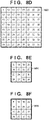
- FIG. 8D shows an 8 ⁇ 8 pixel-sized quantization matrix 803 for the Y component that uses inter-prediction.
- FIG. 8E also shows a 4 ⁇ 4-pixel-sized quantization matrix 804 for the Cb component that uses inter-prediction
- FIG. 8F shows a 4 ⁇ 4-pixel-sized quantization matrix 805 for the Cr component that uses inter-prediction.
- FIG. 8G shows a 4 ⁇ 4 pixel-sized quantization matrix 806 for the Y component that uses intra-prediction.
- FIG. 8H also shows a 2 ⁇ 2-pixel-sized quantization matrix 807 for the Cb component that uses intra-prediction
- FIG. 8I shows a 2 ⁇ 2-pixel-sized quantization matrix 808 for the Cr component that uses intra-prediction.
- FIG. 8J shows a 4 ⁇ 4 pixel-sized quantization matrix 809 for the Y component that uses inter-prediction.
- FIG. 8K also shows a 2 ⁇ 2-pixel-sized quantization matrix 810 for the Cb component that uses inter-prediction, and
- FIG. 8L shows a 2 ⁇ 2-pixel-sized quantization matrix 811 for the Cr component that uses inter-prediction.
- each thick-framed square represents the elements constituting a quantization matrix.
- the 12 types of quantization matrices shown in FIGS. 8A to 8L are held in two-dimensional form, but the respective elements within the quantization matrices are naturally not limited thereto. Also, depending on the size of the subblocks, it is also possible to hold a plurality of quantization matrices for the same color component and the same prediction mode.
- the quantization matrices realize quantization processing that depends on human visual characteristics, the elements of the low frequency component corresponding to the upper left portion of the quantization matrices are smaller, and the elements of the high frequency component corresponding to the lower right portion are larger, as shown in FIGS. 8A to 8L .
- the quantization matrix encoding unit 113 reads out the two-dimensional quantization matrices held in the quantization matrix holding unit 106 in order, and determines the encoding mode of each quantization matrix to be used when encoding the quantization matrix.
- three types of quantization matrix encoding modes are used, namely, a "quantization matrix reference mode", an "inter-quantization matrix difference encoding mode", and an "intra-quantization matrix difference encoding mode”.
- the quantization matrix encoding unit 113 determines, for each quantization matrix, a quantization matrix encoding mode that minimizes the data amount of the encoding result.
- the "inter-quantization matrix difference encoding mode" is a mode in which an encoded quantization matrix that approximates the quantization matrix to be encoded is selected, a difference value of each of the elements is computed, and the computed difference values are encoded.
- the quantization matrix encoding unit 113 encodes a quantization matrix reference index, which is an identifier indicating the quantization matrix to be referenced, and then encodes difference information which is a set of difference values of the respective elements.
- the "intra-quantization matrix difference encoding mode" is used when there are no encoded quantization matrices or when there are no encoded quantization matrices similar to the quantization matrix to be encoded.
- the quantization matrix encoding unit scans each element of the quantization matrix to be encoded, calculates the difference values between the elements, and encodes difference information which is a set of difference values.
- FIG. 12 is a syntax table that is used in encoding the quantization matrix in the present embodiment.
- the encoding processing of the quantization matrices shown in FIGS. 8A to 8L of the present embodiment will be specifically described using this syntax table.
- sizeId indicates the size of the quantization matrix, and quantization matrices of the same size are encoded in succession.
- the initial value of the sizeId in the for loop is "1", and defines that the value will be incremented by "1" every loop and the loop will be repeated as long as sizeId is less than 4. Therefore, in the present embodiment, this means that after the group of 2 ⁇ 2 pixel-sized quantization matrixes is encoded, the group of the 4 ⁇ 4 pixel-sized quantization matrices will be encoded, followed by the group of 8 ⁇ 8 pixel-sized quantization matrices.
- orthogonal transformation from a minimum 2 ⁇ 2 pixel size to a 64 ⁇ 64pixel size is used, and it is also possible to adopt a configuration in which for loops from a 2 ⁇ 2 pixel size whose sizeId is 1 to a 64 ⁇ 64 pixel size whose sizeId is 6 are set, and quantization matrices respectively corresponding thereto are encoded.
- the maximum orthogonal transformation size that is, the maximum size of the subblocks is 8 ⁇ 8, and thus the upper limit value of a for loop is a sizeId of 3 corresponding to the 8 ⁇ 8 pixel size. This enables unnecessary quantization matrix encoding to be omitted and redundant code generation to be prevented, by setting the upper limit value of the for loop based on the maximum value of the orthogonal transformation size that is actually used.
- the encoding order of the quantization matrices of FIGS. 8A to 8L is as follows.
- the 2 ⁇ 2 pixel-sized quantization matrices of FIGS. 8H, 8I , 8K and 8L are encoded.
- the 4 ⁇ 4 pixel-sized quantization matrices of FIGS. 8G , 8B , 8C , 8J , 8E and 8F are encoded.
- the 8 ⁇ 8 pixel-sized quantization matrices of FIG. 8A and 8D are encoded.
- the quantization matrix encoding unit 113 When using the quantization matrix reference mode, the quantization matrix encoding unit 113 encodes the quantization matrix reference index next. This corresponds to scaling_list_pred_matrix_id_delta in the syntax table in FIG. 12 .
- the quantization matrix 801 in FIG. 8B is the same as the quantization matrix 806 in FIG. 8G encoded most recently. Therefore, at the time of encoding the quantization matrix 801 in FIG. 8B , the quantization matrix encoding unit 113 selects the quantization matrix reference mode, and encodes 0 indicating that the quantization matrix 801 is the quantization matrix encoded most recently as the quantization matrix reference index. This enables quantization matrices that are the same as the quantization matrix 806 in FIG. 8G to be encoded. Note that when the quantization matrix encoded second most recently is used, the quantization matrix reference index will be "1".
- FIGS. 9A to 9C show the scanning method that is used in the present embodiment when a two-dimensional matrix in arranged one dimensionally, with FIGS. 9A, 9B and 9C respectively corresponding to 8 ⁇ 8, 4 ⁇ 4 and 2 ⁇ 2 quantization matrices.
- the quantization matrix encoding unit 113 arranges the two-dimensional difference value matrix 1000 in FIG. 10A in a one-dimensional difference value matrix 1001 shown in FIG. 10B , using the scanning method shown in FIG. 9B .
- the quantization matrix encoding unit 113 then encodes each difference value of the matrix 1001 in FIG. 10B .
- the absolute value of each difference value in FIG. 10B is "1" or less, but there may be cases where the absolute value is greater than 1.
- the quantization matrix encoding unit 113 scans each element of the quantization matrix to be encoded, using one of FIGS. 9A to 9C , calculates the difference between two consecutive elements, and arranges the differences in a one-dimensional matrix.
- the quantization matrix encoding unit 113 then encodes each difference value arranged in the one-dimensional matrix as difference information. This corresponds to scaling list delta _coef in the syntax table in FIG. 12 . For example, since the quantization matrix 806 in FIG.
- the quantization matrix encoding unit 113 necessarily selects the intra-quantization matrix difference encoding mode. Therefore, the quantization matrix encoding unit 113 scans the quantization matrix 806 in FIG. 8G using FIG. 9B , and computes, for every element, the difference from the immediately previous element in scanning order. The quantization matrix encoding unit 113 arranges the calculated differences in a one-dimensional matrix and obtains a one-dimensional difference value matrix 1002 shown in FIG.
- the 4 ⁇ 4 pixel-sized quantization matrix in FIG. 8G is scanned by the scanning method shown in FIG. 9B , whereby an element 13 located immediately below the first element 6 located in the upper left is scanned, and +7 which is the difference is computed.
- a predetermined initial value e.g. 8 8
- the initial value need only be the same as the decoding apparatus.
- the quantization matrix encoding unit 113 then encodes each difference value in FIG. 10C .
- the fifth “scaling_list_pred_mode_id ⁇ [sizeId][matrixId]" from the top in FIG. 12 is a parameter indicating the encoding mode of quantization matrices that depends on sizeId and matrixId.
- a quantization matrix one of FIGS. 8A to 8L ) specified by sizeId and matrixId is encoded in accordance with the above three encoding modes, and the encoding mode that minimizes the generated encoding is determined.
- Information (0 to 2 described above) specifying the determined encoding mode is then set as a parameter thereof.
- the quantization matrix encoding unit 113 generates quantization matrix encoded data as an encoding result of each quantization matrix generated using the quantization matrix encoding modes in the manner described above.
- the quantization matrix encoding unit 113 of the present embodiment encodes the individual elements of a one-dimensional difference value matrix using the encoding table shown in FIG. 11A by allocating a code word which is a binary code, and generates quantization matrix encoded data.
- the encoding table is not limited thereto, and an encoding table shown in FIG. 11B , for example, may be used. In this way, the quantization matrix encoding unit 113 outputs the generated quantization matrix encoded data to the downstream integration encoding unit 111.
- the integration encoding unit 111 integrates the quantization matrix encoded data into header information required in encoding the image data.
- Image data of one frame input from the input terminal 101 is supplied to the block division unit 102.
- the block division unit 102 divides the input image data of one frame into a plurality of basic blocks, and outputs image data in basic block units to the prediction unit 104.
- image data in basic block units of 8 ⁇ 8 pixels will be supplied to the prediction unit 104.
- the prediction unit 104 executes prediction processing on the image data in basic block units input from the block division unit 102. Specifically, the prediction unit 104 determines the subblock division for dividing the basic blocks into smaller subblocks, and further determines the prediction mode such as intra-prediction or inter-prediction in subblock units.
- Intra-prediction involves generating prediction pixels of the block to be encoded using encoded pixels located spatially around the block to be encoded, and also generating an intra-prediction mode indicating an intra-prediction method such as horizontal prediction, vertical prediction or DC prediction.
- Inter-prediction involves generating prediction pixels of the block to be encoded using encoded pixels of a frame that differs temporally from the block to be encoded, and also generating motion information indicating a reference frame, a motion vector or the like.
- FIGS. 7A to 7F Subblock division methods will be described with reference to FIGS. 7A to 7F .
- the thick frames of blocks 700 to 705 in FIGS. 7A to 7F are the same 8x8 pixel size as the basic blocks. Each rectangle within the thick frame represents a subblock.
- FIG. 7B represents an example of conventional square subblock division, with an 8x8 pixel basic block 701 being divided into four 4 ⁇ 4-pixel subblocks.
- FIGS. 7C to 7F represent an example of rectangular subblock division.
- FIG. 7C shows that a basic block 702 is divided into two 4x8 pixel-sized subblocks (long vertically).
- FIG. 7D shows that a basic block 703 is divided into two 8 ⁇ 4 pixel-sized subblocks (long horizontally).
- FIGS. 7E and 7F show basic blocks 704 and 705 divided into three rectangular subblocks by a ratio of 1: 2: 1, although the division methods differ therebetween. In this way, encoding is performed using not only
- FIG. 7A In which the 8 ⁇ 8 pixel-sized basic block is not divided into subblocks and FIG. 7B in which the basic block is divided in four being used, but the subblock division method is not limited thereto.
- Tri-tree division such as FIGS. 7E and 7F or bi-tree division such as is shown in FIGS. 7C and 7D may be used.
- FIGS. 7C and 7D When subblock division other than FIGS. 7A and 7B are also used, quantization matrices corresponding to the subblocks that are used are generated in the quantization matrix holding unit 103. Also, the generated quantization matrices will be encoded by the quantization matrix encoding unit 113.
- the prediction unit 104 generates prediction image data from the determined prediction mode and an encoded region stored in the frame memory 108, and further computes prediction errors in pixel units from prediction image data corresponding to the subblock of interest in the input image data, and outputs the computed errors to the transformation/quantization unit 105. Also, the prediction unit 104 outputs information such as subblock division and prediction mode to the encoding unit 110 and the image reconstruction unit 107 as prediction information.
- the transformation/quantization unit 105 performs orthogonal transformation and quantization on the prediction errors input from the prediction unit 104 and generates residual coefficients. Specifically, the transformation/quantization unit 105, first, performs orthogonal transformation processing that depends on the size of the subblocks on the prediction errors and generates orthogonal transform coefficients. The transformation/quantization unit 105 then quantizes the orthogonal transform coefficients using the quantization matrices stored in the quantization matrix holding unit 103 according to the prediction mode and color component, and generates residual coefficients. In the present embodiment, in the case where subblock division is not performed and the intra-prediction mode is used, the quantization matrix in FIG. 8A is used for the orthogonal transform coefficients of the Y component, the quantization matrix in FIG.
- the quantization matrix in FIG. 8B is used for the orthogonal transform coefficients of the Cb component, and the quantization matrix in FIG. 8C for the orthogonal transform coefficients of the Cr component.
- the quantization matrix in FIG. 8D is used for the orthogonal transform coefficients of the Y component
- the quantization matrix in FIG. 8E is used for the orthogonal transform coefficients of the Cb component
- the quantization matrix in FIG. 8F is used for the orthogonal transform coefficients of the Cr component.
- the quantization matrix in FIG. 7B is performed and the intra-prediction mode is used.
- the quantization matrix in FIG. 8G is used for the orthogonal transform coefficients of the Y component
- the quantization matrix in FIG. 8H is used for the orthogonal transform coefficients of the Cb component
- the quantization matrix in FIG. 8I is used for the orthogonal transform coefficients of the Cr component.
- the quantization matrix in FIG. 8J is used for the orthogonal transform coefficients of the Y component
- the quantization matrix in FIG. 8K is used for the orthogonal transform coefficients of the Cb component
- the quantization matrix in FIG. 8L is used for the orthogonal transform coefficients of the Cr component.
- the quantization matrices used are, however, not limited thereto.
- the generated residual coefficients and chroma integration information are output to the encoding unit 110 and the inverse quantization/inverse transformation unit 106.
- the inverse quantization/inverse transformation unit 106 reconstructs the orthogonal transform coefficients by inverse quantization of the residual coefficients input from the transformation/quantization unit 105, using the corresponding quantization matrices stored in the quantization matrix holding unit 103.
- the inverse quantization/inverse transformation unit 106 further performs inverse orthogonal transformation on the reconstructed orthogonal transform coefficients to reconstruct the prediction errors.
- the quantization matrices corresponding to the size and color component of the subblocks to be encoded are used, similarly to the transformation/quantization unit 105.
- the inverse quantization/inverse transformation unit 106 performs inverse quantization using the same quantization matrices used by the transformation/quantization unit 105.
- the quantization matrix in FIG. 8A is used for the orthogonal transform coefficients of the Y component
- the quantization matrix in FIG. 8B is used for the orthogonal transform coefficients of the Cb component
- the quantization matrix in FIG. 8C is used for the orthogonal transform coefficients of the Cr component.
- the quantization matrix in FIG. 8D is used for the orthogonal transform coefficients of the Y component
- the quantization matrix in FIG. 8E is used for the orthogonal transform coefficients of the Cb component
- the prediction errors reconstructed by performing inverse orthogonal transformation to the orthogonal transform coefficients thus reconstructed are output to the image reconstruction unit 107.
- the encoding unit 110 entropy encodes the residual coefficients and chroma integration information in subblock units generated by the transformation/quantization unit 105 and the prediction information input from the prediction unit 104, and generate encoded data. While no particular method of entropy encoding is designated, methods such as Golomb coding, arithmetic coding and Huffman coding can be used.
- the encoding unit 110 outputs the generated encoded data to the integration encoding unit 111.
- FIG. 6A is an example of the data structure of the output bitstream in the present embodiment.
- the sequence header includes the encoded data of the quantization matrices and is constituted by the encoding results of the quantization matrices.
- the position where the encoded data of the quantization matrices is stored is, however, not limited thereto, and a configuration may also naturally be adopted in which the encoded data is arranged in a picture header portion such as is shown in FIG. 6B or a header portion spanning a plurality of pictures. Also, when changing quantization matrices in a single sequence, updating is also possible by newly encoding quantization matrices.
- all of the quantization matrices may be overwritten, and it is also possible to adopt a configuration in which some of the quantization matrices are changed by specifying the size, prediction mode and color component of the quantization matrices corresponding to the quantization matrices to be overwritten.
- the control unit 150 controls the quantization matrix holding unit 103 to generate and hold two-dimensional quantization matrices.
- the quantization matrix holding unit 103 of the present embodiment is compatible with 8 ⁇ 8 to 2 ⁇ 2 pixel-sized blocks, and generates and holds quantization matrices that correspond to the respective color components and prediction modes shown in FIGS. 8A to 8L .
- step S303 the control unit 150 controls the integration encoding unit 111 to encode and output header information required in encoding the image data together with the generated quantization matrix encoded data.
- step S304 the control unit 150 controls the block division unit 102 to divide the input image in frame units into basic block units.
- step S306 the control unit 150 controls the transformation/quantization unit 105 to perform orthogonal transformation on the prediction errors computed in step S305, and generate orthogonal transform coefficients. Furthermore, the control unit 150 controls the transformation/quantization unit 105 to perform quantization using the quantization matrices generated and held in step S301, and generate residual coefficients.
- the quantization matrices in FIGS. 8A to 8L are used according to the subblock size, the prediction mode and the color component.
- step S307 the control unit 150 controls the inverse quantization/inverse transformation unit 106 to perform inverse quantization on the residual coefficients generated in step S306, using the quantization matrices generated and held in step S301, and reconstruct the orthogonal transform coefficients.
- inverse quantization processing is performed using the same quantization matrices as used in step S306.
- Inverse orthogonal transformation is then performed on the reconstructed orthogonal transform coefficients and the prediction errors are reconstructed.
- step S308 the control unit 150 controls the image reconstruction unit 107 to reconstruct the prediction image based on the prediction information generated in step S305, reconstruct the image data from the reconstructed prediction image and the prediction errors generated in step S307, and store the reconstructed image data in the frame memory 108.
- step S309 the control unit 150 controls the encoding unit 110 to perform encoding of the prediction information generated in step S305 and the residual coefficient generated in step S306, and generate encoded data. Also, the encoding unit 110 outputs the generated encoded data to the integration encoding unit 111. The integration encoding unit 111 positions the encoded data from the encoding unit 110 to follow the header generated previously, and outputs the resultant data.
- step S311 the control unit 150 controls the in-loop filter unit 109 to perform in-loop filtering on the image data reconstructed in step S308 and generate a filtered image, and ends the processing.
- the generated code amount of the quantization matrices can be suppressed, particularly by determining and encoding the quantization matrix encoding mode that minimizes the generated code amount of the quantization matrices in step S302.
- a configuration is adopted in which the quantization matrices are encoded in ascending order of size, but a configuration may also be adopted in which the quantization matrices are encoded in descending order of size. It is thereby possible to further reduce the data amount of the quantization matrices, particularly in the aforementioned case where reference between quantization matrices of different sizes is possible.
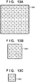
- the reference target of the quantization matrices is limited to encoded quantization matrices, but a configuration can also be adopted in which the reference target is flat quantization matrices, such as is shown in FIGS. 13A to 13C , that are standard in the case where quantization matrices are not used. It is thereby possible to further reduce the data amount of quantization matrices, particularly in the case where the quantization matrices to be encoded approximate a flat quantization matrix.
- FIG. 2 is a block configuration diagram of an image decoding apparatus that decodes encoded image data generated by the image encoding apparatus.
- FIG. 2 the configuration and operations related to decoding processing will be described with reference to FIG. 2 .
- the image decoding apparatus has a control unit 250 that administers overall control of the apparatus.
- the control unit 250 has a CPU, a ROM for storing programs that are executed by the CPU, and a RAM that is utilized as a work area of the CPU.
- the image decoding apparatus has an input terminal 201, a separation and decoding unit 202, a decoding unit 203, an inverse quantization/inverse transformation unit 204, an image reconstruction unit 205, a frame memory 206, an in-loop filter unit 207, an output terminal 208 and a quantization matrix decoding unit 209.
- the input terminal 201 inputs encoded bitstreams, with the input source being a storage medium storing encoded streams, for example, but encoded bitstreams may be input from a network, and there is no limitation on the type of encoded bitstream.
- the separation and decoding unit 202 separates information relating to decoding processing and encoded data relating coefficients from the bitstream, and decodes encoded data that is in the header portion of the bitstream.
- the separation and decoding unit 202 of the present embodiment separates quantization matrix encoded data and outputs the separated quantization matrix encoded data to the quantization matrix decoding unit 209. Also, the separation and decoding unit 202 outputs encoded data of the image to the decoding unit 203. That is, the separation and decoding unit 202 performs the reverse operation from the integration encoding unit 111 in FIG. 1 .
- the quantization matrix decoding unit 209 reconstructs and holds quantization matrices by decoding the quantization matrix encoded data supplied from the separation and decoding unit 202.
- the decoding unit 203 decodes the encoded data of the image output from the separation and decoding unit 202 and reconstructs residual coefficients and prediction information in subblock units.
- the inverse quantization/inverse transformation unit 204 reconstructs prediction errors by performing inverse quantization on the residual coefficients of the subblock of interest using the reconstructed quantization matrices, obtaining coefficients subjected to inverse quantization, and executing inverse orthogonal transformation, similarly to the inverse quantization/inverse transformation unit 106 in FIG. 1 .
- the image reconstruction unit 205 generates prediction image data with reference to the frame memory 206 as appropriate based on the input prediction information.
- the image reconstruction unit 205 then generates reconstruction image data of the subblock of interest from the prediction errors reconstructed with the prediction image data and the inverse quantization/inverse transformation unit 204, and stores the generated reconstruction image data in the frame memory 206.
- the in-loop filter unit 207 performs in-loop filtering such as deblocking filtering on the reconstruction image data stored in the frame memory 206, and re-stores the filtered image data in the frame memory 206, similarly to the in-loop filter unit 109 in FIG. 1 .
- the output terminal 208 sequentially outputs frame images stored in the frame memory 206 externally.
- the output destination is generally a display device, but may be other devices.
- encoded bitstreams are input in frame units.
- the bitstream for one frame input from the input terminal 201 is supplied to the separation and decoding unit 202.
- the separation and decoding unit 202 separates information relating to the decoding processing and encoded data relating to coefficients from the bitstream, and decodes the encoded data that is in the header portion of the bitstream.
- the separation and decoding unit 202 then supplies quantization matrix encoded data that is included in the header portion to the quantization matrix decoding unit 209, and supplies encoded data of the image data to the decoding unit 203.
- the separation and decoding unit 202 first extracts quantization matrix encoded data from the sequence header of the bitstream shown in FIG. 6A , and outputs the extracted quantization matrix encoded data to the quantization matrix decoding unit 209.
- quantization matrix encoded data corresponding to the quantization matrices shown in FIGS. 8A to 8L is extracted and output.
- encoded data in basic block units of the picture data is extracted and output to the decoding unit 203.
- the quantization matrix decoding unit 209 first, decodes the input quantization matrix encoded data, and reconstructs the encoding result of each quantization matrix generated on the encoding side, based on the syntax table shown in FIG. 12 .
- the encoding result of each quantization matrix is constituted by a quantization matrix encoding mode and data corresponding to the quantization matrix encoding mode.
- the quantization matrix encoding mode that is, scaling_list_pred_mode_idx in the syntax table in FIG. 12
- the quantization matrix encoding result is constituted by a quantization matrix encoding mode (0) and a quantization matrix reference index.
- the quantization matrix reference index indicates that the quantization matrix to be referenced is the most recently decoded quantization matrix
- the quantization matrix reference index will be 0. If the quantization matrix reference index is 1, the second most recently decoded quantization matrix is referenced.
- the quantization matrix 209 knows that the 4 ⁇ 4 quantization matrix for intra-prediction and the Cb component is the same as the quantization matrix 806 in FIG. 8G for intra-prediction and the Y component, and reconstructs the quantization matrix 801 in FIG. 8B .
- the quantization matrix encoding mode that is, scaling_list_pred_mode_idx in the syntax table in FIG. 12
- the quantization matrix encoding result is constituted by a quantization matrix encoding mode (1), a quantization matrix reference index and difference information.
- the quantization matrix reference index indicates that the quantization matrix to be referenced is the most recently decoded quantization matrix
- the quantization matrix reference index will be 0. If the quantization matrix reference index is 1, the second most recently decoded quantization matrix is referenced.
- the quantization matrix decoding unit 209 decodes the difference information, that is, scaling_list_pred_delta in the syntax table in FIG. 12 , for the number of elements in the quantization matrix, and reconstructs the one-dimensional difference value matrix 1001 shown in FIG. 10B .
- the quantization matrix decoding unit 209 arranges the one-dimensional difference value matrix 1001 in FIG. 10B two dimensionally using the scanning method in FIG.
- the quantization matrix decoding unit 209 then adds each difference value of the two-dimensional difference value matrix 1000 in FIG. 10A to the respective element of the quantization matrix 801 to be referenced in FIG. 8B , and reconstructs the quantization matrix 802 in FIG. 8C .
- the quantization matrix encoding mode that is, scaling_list_pred_mode_idx in the syntax table in FIG. 12
- the quantization matrix encoding result is constituted by a quantization matrix encoding mode (2) and difference information.
- the quantization matrix decoding unit 209 is arranged two dimensionally using the scanning method in FIG. 9B while adding each difference value within the one-dimensional difference value matrix 1002 in FIG. 10C to the corresponding immediately previous element, and reconstructs the quantization matrix 806 in FIG. 8G .
- the encoding table in FIG. 11A is used in decoding the difference information, but the encoding table in FIG. 11B may also be used. In short, the same encoding table as on the encoding side may be used.
- the quantization matrix decoding unit 209 then holds the quantization matrices 800 to 811 thus reconstructed.
- the operation is the reverse of the operation by the quantization matrix encoding unit 113 on the encoding side.
- the decoding unit 203 decodes the encoded data supplied from the separation and decoding unit 202, reconstructs the prediction information, and further reconstructs the residual coefficients. First, the decoding unit 203 reconstructs the prediction information and acquires the prediction mode that is used in the subblocks. The decoding unit 203 outputs the reconstructed residual coefficients to the inverse quantization/inverse transformation unit 204, and outputs the reconstructed prediction information to the image reconstruction unit 205.
- the inverse quantization/inverse transformation unit 204 performs inverse quantization on the input residual coefficients using the quantization matrices reconstructed by the quantization matrix decoding unit 209 to generate orthogonal transform coefficients, and further performs inverse orthogonal transformation to reconstruct the prediction errors.
- the inverse quantization/inverse transformation unit 204 performs inverse quantization using the quantization matrices corresponding to the size and color component of the decoded subblocks, similarly to the inverse quantization/inverse transformation unit 106 on the encoding side. That is, in the case where subblock division is not performed and the intra-prediction mode is used, the quantization matrix in FIG. 8A is used for the orthogonal transform coefficients of the Y component, the quantization matrix in FIG.
- the quantization matrix in FIG. 8B is used for the orthogonal transform coefficients of the Cb component
- the quantization matrix in FIG. 8C is used for the orthogonal transform coefficients of the Cr component.
- the quantization matrix in FIG. 8D is used for the orthogonal transform coefficients of the Y component
- the quantization matrix in FIG. 8E is used for the orthogonal transform coefficients of the Cb component
- the quantization matrix in FIG. 8F is used for the orthogonal transform coefficients of the Cr component.
- the quantization matrix in FIG. 7B is performed and the intra-prediction mode is used
- the quantization matrix in FIG. 8G is used for the orthogonal transform coefficients of the Y component
- the quantization matrix in FIG. 8H is used for the orthogonal transform coefficients of the Cb component
- the quantization matrix in FIG. 8I is used for the orthogonal transform coefficients of the Cr component.
- the quantization matrix in FIG. 8J is used for the orthogonal transform coefficients of the Y component
- the quantization matrix in FIG. 8K is used for the orthogonal transform coefficients of the Cb component
- the quantization matrix in FIG. 8L is used for the orthogonal transform coefficients of the Cr component.
- the prediction errors reconstructed by performing inverse orthogonal transformation on the orthogonal transform coefficients thus reconstructed are output to the image reconstruction unit 205.
- the quantization matrices that are used are, however, not limited thereto, and may be the same as the quantization matrices used by the transformation/quantization unit 105 and the inverse quantization/inverse transformation unit 106 on the encoding side.
- the image reconstruction unit 205 reconstructs the prediction image with reference to the frame memory 206 as appropriate, based on the prediction information input from the decoding unit 203.
- intra-prediction and inter-prediction are used, similarly to the prediction unit 104 on the encoding side. Since the specific prediction processing is similar to the prediction unit 104 on the encoding side, description thereof will be omitted.
- the image reconstruction unit 205 reconstructs image data from this prediction image and the prediction errors input from the inverse quantization/inverse transformation unit 204, and stores the reconstructed image data in the frame memory 206. The stored image data is used for reference during prediction.
- the in-loop filter unit 207 reads out the reconstruction image from the frame memory 206 and performs in-loop filtering such as deblocking filtering, similarly to the in-loop filter unit 109 on the encoding side. The in-loop filter unit 207 then re-stores the filtered image in the frame memory 206.
- the reconstruction image stored in the frame memory 206 is ultimately output externally (typically to a display device) from the output terminal 208.
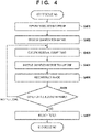
- FIG. 4 is a flowchart showing decoding processing by the control unit 250 in the image decoding apparatus according to the present embodiment.
- step S401 the control unit 250 controls the separation and decoding unit 202 to separate information relating to decoding processing and encoded data relating to coefficients from the bitstream, and decode the encoded data of the header portion. More specifically, the separation and decoding unit 202 supplies the encoded data of the quantization matrices to the quantization matrix decoding unit 209, and supplies the encoded data of the image to the decoding unit 203.
- step S402 the control unit 250 controls the quantization matrix decoding unit 209 to decode the quantization matrix encoded data reconstructed in step S401 based on the syntax table in FIGS. 12 , and reconstruct and hold the quantization matrices 801 to 811 shown in FIGS. 8A to 8L .
- the specific operations of the quantization matrix decoding unit 209 referred to here have been described and will thus be omitted.
- step S403 the control unit 250 controls the decoding unit 203 to decode the encoded data separated in step S401, reconstruct the prediction information, and reconstruct the residual coefficients.
- step S404 the control unit 250 controls the inverse quantization/inverse transformation unit 204 to perform inverse quantization on the residual coefficients using the quantization matrices reconstructed in step S402 and generate orthogonal transform coefficients.
- the inverse quantization/inverse transformation unit 204 further performs inverse orthogonal transformation and reconstructs the prediction errors.
- the quantization matrices that are used in the inverse quantization processing are determined according to characteristics of the subblocks to be decoded such as color component and size. That is, the inverse quantization/inverse transformation unit 204 performs inverse quantization using the quantization matrices in FIGS. 8A to 8L according to characteristics of the subblocks such as size, prediction mode and color component.
- the quantization matrices that are used are, however, not limited thereto, and may be the same as the quantization matrices used on the encoding side.
- step S405 the control unit 250 controls the image reconstruction unit 205 to reconstruct the image based on the prediction information generated in step S403. Specifically, the image reconstruction unit 205 reconstructs the prediction image with reference to the frame memory 206, based on the prediction information. At this time, the image reconstruction unit 205 uses intra-prediction and inter-prediction, similarly to step S305 on the encoding side. The image reconstruction unit 205 then reconstructs the image data from the reconstructed prediction image and the prediction errors generated in step S404, and stores the reconstruction image data in the frame memory 206.
- step S406 the control unit 250 determines whether decoding of all the basic blocks in the frame of interest has ended, and advances to step S407 if ended, and, if there are any basic blocks that have not been decoded, returns the processing to step S403 in order to set the next basic block as the decoding target.
- step S407 the control unit 250 controls the in-loop filter unit 207 to perform in-loop filtering on the image data reconstructed in step S405 and generate a filtered image, and ends the processing.
- an encoded bitstream generated by the image encoding apparatus described above that is, a bitstream encoded in an appropriate quantization matrix encoding mode and in which the generated code amount of the quantization matrix is suppressed, can be decoded.
- a configuration is adopted in which the quantization matrices are decoded in ascending order of size, but a configuration may also be adopted in which the quantization matrices are decoded in descending order of size. It is thereby possible to decode a bitstream in which the data amount of the quantization matrices has been further reduced, particularly in the aforementioned case where reference between quantization matrices of different sizes is possible.
- the processing units included in the image encoding apparatus and the image decoding apparatus of the first embodiment are described as being constituted by hardware. However, the processing that is performed in each processing unit shown in the diagrams may be configured with a computer program.
- a CPU 501 performs overall control of the computer using computer programs and data that are stored in a RAM 502 and a ROM 503, and executes the respective processing described above as performed by an image processing apparatus according to the above embodiment. That is, the CPU 501 functions as the respective processing units shown in FIGS. 1 and 2 .
- the RAM 502 has an area for temporarily storing data acquired from outside via an external storage device 506 and an I/F (interface) 507. Furthermore, the RAM 502 is also utilized as a work area that the CPU 501 uses when executing various processing.
- the RAM 502 can be allocated as frame memory or various other areas can be provided as appropriate, for example.
- the ROM 503 stores setting data of the computer and a boot program.
- An operation unit 504 is constituted by a keyboard, a mouse and the like, and various instructions can be input to the CPU 501 by the user of the computer performing operations.
- a display unit 505 displays the results of processing by the CPU 501.
- the display unit 505 is constituted by a liquid crystal display, for example.
- the external storage device 506 is a large capacity information storage device typified by a hard disk drive device.
- the external storage device 506 stores an OS (operating system) and computer programs (application programs) for causing the CPU 501 to realize the functions of the various units shown in FIGS. 1 and 2 .
- the respective image data to be processed may be stored in the external storage device 506.
- the computer programs and data that are stored in the external storage device 506 are loaded to the RAM 502 as appropriate in accordance with control of the CPU 501 and undergo processing by the CPU 501.
- Networks such as a LAN and the Internet and other devices such as a projection device and a display device can be connected to the I/F 507, and the computer is able to acquire and send various information via the I/F 507.
- Reference numeral 508 denotes a bus that connects the above units.
- the CPU 501 executes the boot program stored in the ROM 503, and loads the OS stored in the external storage device 506 to the RAM 502 and executes the loaded OS.
- the CPU 501 under the control of the OS, then loads application programs related to encoding or decoding from the external storage device 506 to the RAM 502 and executes the loaded application programs.
- the CPU 501 functions as the respective processing units in FIG. 1 or FIG. 2
- the apparatus functions as an image encoding apparatus or an image decoding apparatus.
- the order of the quantization matrices that are encoded is the same as the first embodiment, and is initially the 2 ⁇ 2 pixel-sized quantization matrices 807 ⁇ 808 ⁇ 810 ⁇ 811 in order, followed by the 4 ⁇ 4 pixel-sized quantization matrices 806 ⁇ 801 ⁇ 802 ⁇ 809 ⁇ 804 ⁇ 806 in order, and finally the 8 ⁇ 8 pixel-sized quantization matrix 800 ⁇ 803 in order.
- variable sizeId is a variable indicating the size of the quantization matrix
- the sizeId is “ 1 "
- the sizeId is "2”
- the sizeId is "3”
- the variable matrixId indicates the order of quantization matrices of the same size.
- the quantization matrices to be encoded are identified by sizeId and matrixId.
- step S1401 the CPU 501 sets the size of the quantization matrix to be encoded to 2 ⁇ 2 pixels by setting the variable sizeId to "1" as the initial value.
- step S1402 the CPU 501 sets the matrixId to "0" as the initial value.
- the quantization matrix 807 in FIG. 8H is set as the quantization matrix of interest to be encoded in the case where this step S1402 is first executed.
- step S1403 the CPU 501 determines whether the matrixId is "0". If matrixId is other than "0", there will be an encoded quantization matrix of the same size as the quantization matrix of interest. Therefore, the CPU 501 advances the processing to step S1404 and performs search processing in the quantization matrix reference mode. In other words, the CPU 501 performs search processing as to whether there is an encoded quantization matrix of the same as the quantization matrix of interest.
- step S1405 the CPU 501 determines whether an encoded quantization matrix of the same as the quantization matrix of interest was found. If it is determined that such a quantization matrix was found, the CPU 501 advances the processing to step S1406, and outputs "0" and a value specifying the matching quantization matrix as encoded data of the quantization matrix of interest. Setting "0" at the start of the encoded data is equivalent to setting the parameter scaling _list_pred_mode_idx to "0".
- the number "6" of 4 ⁇ 4 pixel-sized quantization matrices is greater than the number of quantization matrices of other sizes, and thus the bit number allocated to the value specifying that quantization matrix need only be "3".
- the CPU 501 advances the processing to step S1407.
- step S1403 If it is determined in step S1403 that the matrixId is "0", the CPU 501 advances the processing to step S1409.
- step S1407 the CPU 501 executes the inter-quantization matrix difference encoding mode for the quantization matrix of interest. Then, in step S1408, the CPU 501 obtains "1" and the encoded data generated in the inter-quantization matrix difference encoding mode. Setting "1" at the start of the encoded data is equivalent to setting the parameter scaling _list_pred_mode_idx to "1". A configuration may also be adopted in which information indicating the order of the quantization matrix that is the same as the quantization matrix of interest is output following the value "1" set at the start of the encoded data, and difference encoded data is output thereafter.
- step S1409 the CPU 501 executes the intra-quantization matrix difference encoding mode for the quantization matrix of interest. Then, in step S1410, the CPU 501 obtains "2" and encoded data generated in the inter-quantization matrix difference encoding mode. Setting "2" at the start of the encoded data is equivalent to setting the return value of scaling_list_pred_mode_idx to "2".
- step S1411 the CPU 501 outputs the smaller of the encoded data generated in step S1408 and step S1410 as encoded data of the quantization matrix of interest. Note that, in the case of branching from step S1403 to step S1409, the encoded data generated in the inter-quantization matrix difference encoding mode in step S1409 is output.
- step S1412 the CPU 501 increases the variable matrixId by "1". Then, in step S1413, the CPU 501 determines whether all the quantization matrices of the same size as the quantization matrix of interest have been encoded, based on the variables sizeId and matrixId. If the determination result of step S1413 is "No", the CPU 501 advances the processing to step S1403 and repeats the above processing.
- step S1413 determines whether the quantization matrices of all the sizes have been encoded, based on the variables sizeId and matrixId. If the determination result of step S1415 is "No", there are quantization matrices of a size that have not been encoded, and thus the CPU returns the processing to step S1402. Also, if the determination result of step S1415 is "Yes”, this processing (step S302 in FIG. 3 ) is ended.
- step S1406 it is assured that the encoded data generated in the quantization matrix reference mode will be reduced, and thus comparison with the encoded data generated in other modes is omitted, but naturally such comparison may be performed.
- the present invention can be implemented by processing of supplying a program for implementing one or more functions of the above-described embodiments to a system or apparatus via a network or storage medium, and causing one or more processors in the computer of the system or apparatus to read out and execute the program.
- the present invention can also be implemented by a circuit (for example, an ASIC) for implementing one or more functions.
- the present invention is used in encoding apparatuses/decoding apparatuses that encode/decode still images/moving images.
- the invention can be applied to encoding methods and decoding methods that use quantization matrices.
Landscapes
- Engineering & Computer Science (AREA)
- Multimedia (AREA)
- Signal Processing (AREA)
- Compression Or Coding Systems Of Tv Signals (AREA)
- Compression Of Band Width Or Redundancy In Fax (AREA)
Abstract
Description
- The present invention relates to an image coding apparatus, an image decoding apparatus, control methods for the same, and a program.
- Known encoding methods for compressing and recording moving images include the HEVC (High Efficiency Video Coding) encoding method (hereinafter, simply referred to as HEVC). In order to improve encoding efficiency, HEVC employs basic blocks that are larger than conventional macroblocks (16×16 pixels). These large base blocks are called CTUs (Coding Tree Units), and are up to 64×64 pixels in size. CTUs are further divided into subblocks that serve as units for performing prediction and transformation.
- Also, HEVC uses processing in which coefficients that have undergone orthogonal transformation (hereinafter, referred to as orthogonal transform coefficients), called quantization matrices, are weighted according to the frequency component. By further reducing data of the high frequency component whose deterioration is not readily visible to the human eye, it is possible to enhance compression efficiency while maintaining image quality.
Patent Document 1 discloses a technology for encoding such quantization matrices. - In recent years, activities for carrying out international standardization of more efficient encoding methods as successors to HEVC have commenced. JVET (Joint Video Experts Team) was established between ISO/IEC and ITU-T, and standardization as the VVC (Versatile Video Coding) encoding method (hereinafter, VVC) is ongoing. In order to improve encoding efficiency, the basic blocks in VVC are up to 128×128 pixels in size, and rectangular subblock division is also being considered in addition to conventional square subblock division.
- PTL1:
Japanese Patent Laid-open No. 2013-38758 - The introduction of quantization matrices to VVC similarly to HEVC is also been considered. Furthermore, with VVC, more types of subblock division than HEVC, including rectangular subblocks, are being considered. Since the distribution of orthogonal transform coefficients corresponding to each subblock division differs depending on the size and shape of the orthogonal transformation, it is desirable to define the optimal quantization matrix according to the size and shape of the subblocks. However, if individual quantization matrices are defined for all subblock shapes, the code amount of the quantization matrices will increase unnecessarily.
- The present invention made been made in view of such problems, and provides a technology for suppressing the code amount of quantization matrices.
- In order to solve this problem, an image encoding apparatus of the present invention is provided with the following configuration, for example. That is, an image encoding apparatus for dividing an image into a plurality of blocks, quantizing prediction errors in units of divided blocks and performing encoding, characterized by including:
- quantization means for quantizing the prediction errors of the blocks using a quantization matrix; and
- encoding means for encoding the quantization matrix,
- the encoding means having
- a first mode in which encoding is performed on information indicating that a quantization matrix to be encoded is identical to an encoded quantization matrix, and encoding is not performed on elements of the quantization matrix to be encoded,
- a second mode in which encoding is performed on information indicating to encode a difference between respective elements of a quantization matrix to be encoded and an encoded quantization matrix, and encoding is performed on the difference between the respective elements of the quantization matrix to be encoded and the encoded quantization matrix, and
- a third mode in which encoding is performed on information indicating to encode a difference between elements within a quantization matrix to be encoded, and encoding is performed on the difference between the elements within the quantization matrix to be encoded.
- According to the present invention, it is possible to improve the encoding efficiency of image data by suppressing the code amount of quantization matrices more than before.
- Other features and advantages of the present invention will be apparent from the following description taken in conjunction with the accompanying drawings. Note that the same reference numerals denote the same or like components throughout the accompanying drawings.
- The accompanying drawings, which are incorporated in and constitute a part of the specification, illustrate embodiments of the invention and, together with the description, serve to explain principles of the invention.
-
FIG. 1 is a block configuration diagram of an image encoding apparatus of a first embodiment. -
FIG. 2 is a block configuration diagram of an image decoding apparatus of the first embodiment. -
FIG. 3 is a flowchart showing encoding processing in the image encoding apparatus of the first embodiment. -
FIG. 4 is a flowchart showing decoding processing in the image decoding apparatus of the first embodiment. -
FIG. 5 is a configuration diagram of computer hardware applied in a second embodiment. -
FIG. 6A is a diagram showing an example of the data structure of a bitstream generated by the image encoding apparatus of the first embodiment. -
FIG. 6B is a diagram showing an example of the data structure of a bitstream generated by the image encoding apparatus of the first embodiment. -
FIG. 7A is a diagram showing an example subblock division in the embodiments. -
FIG. 7B is a diagram showing an example subblock division in the embodiments. -
FIG. 7C is a diagram showing an example subblock division in the embodiments. -
FIG. 7D is a diagram showing an example subblock division in the embodiments. -
FIG. 7E is a diagram showing an example subblock division in the embodiments -
FIG. 7F is a diagram showing an example subblock division in the embodiments. -
FIG. 8A is a diagram showing an example of a quantization matrix used in the embodiments. -
FIG. 8B is a diagram showing an example of a quantization matrix used in the embodiments. -
FIG. 8C is a diagram showing an example of a quantization matrix used in the embodiments. -
FIG. 8D is a diagram showing an example of a quantization matrix used in the embodiments. -
FIG. 8E is a diagram showing an example of a quantization matrix used in the embodiments. -
FIG. 8F is a diagram showing an example of a quantization matrix used in the embodiments. -
FIG. 8G is a diagram showing an example of a quantization matrix used in the embodiments. -
FIG. 8H is a diagram showing an example of a quantization matrix used in the embodiments. -
FIG. 8I is a diagram showing an example of a quantization matrix used in the embodiments. -
FIG. 8J is a diagram showing an example of a quantization matrix used in the embodiments. -
FIG. 8K is a diagram showing an example of a quantization matrix used in the embodiments. -
FIG. 8L is a diagram showing an example of a quantization matrix used in the embodiments. -
FIG. 9A is a diagram showing a diagram showing a method for scanning elements of a quantization matrix used in the embodiments. -
FIG. 9B is a diagram showing a diagram showing a method for scanning elements of a quantization matrix used in the embodiments. -
FIG. 9C is a diagram showing a diagram showing a method for scanning elements of a quantization matrix used in the embodiments. -
FIG. 10A is a diagram showing a diagram showing a difference value matrix of a quantization matrix generated in the embodiments. -
FIG. 10B is a diagram showing a diagram showing a difference value matrix of a quantization matrix generated in the embodiments. -
FIG. 10C is a diagram showing a diagram showing a difference value matrix of a quantization matrix generated in the embodiments. -
FIG. 11A is a diagram showing an example of an encoding table used to encode difference values of a quantization matrix. -
FIG. 11B is a diagram showing an example of an encoding table used to encode difference values of a quantization matrix. -
FIG. 12 is a diagram showing an example of a syntax table for quantization matrices that is used in the embodiments. -
FIG. 13A is a diagram showing an example of a reference quantization matrix that is used in the embodiments. -
FIG. 13B is a diagram showing an example of a reference quantization matrix that is used in the embodiments. -
FIG. 13C is a diagram showing an example of a reference quantization matrix that is used in the embodiments. -
FIG. 14 is a flowchart showing a procedure for encoding a quantization matrix. - Hereinafter, embodiments will be described in detail with reference to the accompanying drawings. Note that the following embodiments do not limit the invention according to the patent claims. The embodiments describe a plurality of features, but not all of these features are essential to the invention, and the features may be discretionarily combined. Furthermore, constituent elements that are the same or similar are given the same reference numerals in the accompanying drawings, and redundant description thereof will be omitted.
- The embodiments describe a plurality of features, but not all of these features are essential to the invention, and the features may be discretionarily combined. Furthermore, in the accompanying drawings, constituent elements that are the same or similar are given the same reference numerals, and redundant description thereof will be omitted.
-
FIG. 1 is a block configuration diagram of an image encoding apparatus of a first embodiment. The image encoding apparatus has acontrol unit 150 that administers overall control of the apparatus. Thiscontrol unit 150 has a CPU, a ROM for storing programs executed by the CPU, and a RAM that is utilized as a work area of the CPU. The image encoding apparatus has aninput terminal 101, ablock division unit 102, a quantizationmatrix holding unit 103, aprediction unit 104, a transformation/quantization unit 105, an inverse quantization/inverse transformation unit 106, animage reconstruction unit 107, aframe memory 108, an in-loop filter unit 109, anencoding unit 110, anintegration encoding unit 111, anoutput terminal 112, and a quantizationmatrix encoding unit 113. - The
input terminal 101 inputs, in units of frames, image data for encoding generated by an image data source. The image data source is not limited in terms of type, being an image capturing apparatus, file server or storage medium storing image data for encoding or the like. Theoutput terminal 112 outputs encoded data to an output destination device, and the output destination device is also not particularly limited, being a storage medium, file server or the like. - The
block division unit 102 divides the images of input frames into a plurality of basic blocks, and outputs one basic block of each frame in order to thedownstream prediction unit 104. - The quantization
matrix holding unit 103 generates a plurality of quantization matrices prior to encoding and holds the generated quantization matrices in an internal memory not shown. The method for generating quantization matrices is not particularly limited, and may involve quantization matrices being input by a user or computed from the characteristics of input images, or quantization matrices designated in advance as initial values being used. The quantizationmatrix holding unit 103 in the present embodiment generates and holds 8×8, 4×4 and 2×2 pixel-sized two-dimensional quantization matrices 800 to 811 compatible with orthogonal transformation an shown inFIGS. 8A to 8L . Here,quantization matrices quantization matrices - The
prediction unit 104 determines subblock division for image data in basic block units, performs processing such as intra-prediction which is prediction within frames in subblock units and inter-prediction which is prediction between frames, and generates prediction image data. Furthermore, theprediction unit 104 computes and outputs prediction errors in pixel units from subblocks in the input image data and corresponding prediction image data. Also, theprediction unit 104 outputs information required in prediction, such as subblock division, prediction mode and motion vectors, together with the prediction errors. Henceforth, this information required in prediction will be referred to as prediction information. - The transformation/
quantization unit 105 obtains orthogonal transform coefficients by performing, in subblock units, orthogonal transformation of prediction errors of the subblocks input from theprediction unit 104. Furthermore, the transformation/quantization unit 105 performs quantization of the orthogonal transform coefficients using the quantization matrices stored in the quantizationmatrix holding unit 103, and obtains residual coefficients (quantized orthogonal transform coefficients). - The inverse quantization/
inverse transformation unit 106 inputs the residual coefficients from the transformation/quantization unit 105, performs inverse quantization using the corresponding quantization matrices stored in the quantizationmatrix holding unit 103, and reconstructs the orthogonal transform coefficients. The inverse quantization/inverse transformation unit 106 further performs inverse orthogonal transformation on the orthogonal transform coefficients to reconstruct the prediction errors. - The
image reconstruction unit 107 generates prediction image data by referring to theframe memory 108 as appropriate, based on the prediction information output from theprediction unit 104. Theimage reconstruction unit 107 generates reconstruction image data by adding the prediction errors input from the inverse quantization/inverse transformation unit 106 to the generated prediction image data, and stores the generated reconstruction image data in theframe memory 108. - The in-
loop filter 109 performs in-loop filtering such as deblocking filtering and sample adaptive offsetting on the reconstruction image stored in theframe memory 108, and again stores the filtered image data in theframe memory 108. - The
encoding unit 110 encodes the residual coefficients output from the transformation/quantization unit 105 and the prediction information output from theprediction unit 104 to generate encoded data, and outputs the encoded data to theintegration encoding unit 111. - The quantization
matrix encoding unit 113 encodes the quantization matrices (seeFIGS. 8A to 8L ) held in the quantizationmatrix holding unit 103, generates quantization matrix encoded data, and outputs the quantization matrix encoded data to theintegration encoding unit 111. - The
integration encoding unit 111 generates header encoded data including the quantization matrix encoded data output from the quantizationmatrix encoding unit 113. Theintegration encoding unit 111 then positions the encoded data output from theencoding unit 110 to follow the header encoded data and forms a bitstream. Theintegration encoding unit 111 then outputs the formed bitstream via theoutput terminal 112. - Here, the image encoding operation in the image encoding apparatus will be described below in more detail. In the present embodiment, a configuration is adopted in which moving image data having a 4:2:0 color format is input from the
input terminal 101 in frame units at a predetermined frame rate (e.g., 30 frames/second), but a configuration may also be adopted in which still image data is input at one frame/minute. Also, in the present embodiment, for descriptive purposes, theblock division unit 101 will be described as dividing the image data input from theinput terminal 101 into a basic block of 8×8 pixels. That is, a basic block of 8×8 pixels includes a luma (Y) component of 8×8 pixels and chroma (Cb and Cr) components of 4×4 pixels. Note that this is to facilitate understanding, and the invention is not limited to the above numerical values (sizes). - Prior to encoding an image, generation and encoding of quantization matrices is performed.
- The quantization
matrix holding unit 103, first, generates and holds quantization matrices. Specifically, the quantizationmatrix holding unit 103 generates quantization matrices, according to the size of the subblocks to be encoded and the type of prediction method. In the present embodiment, the quantizationmatrix holding unit 103 generates a quantization matrix corresponding to an 8×8 pixel base block that has is not been divided into subblocks shown inFIG. 7A and a quantization matrix corresponding to 4×4 pixel subblocks obtained by performing quad-tree division on the basic block shown inFIG. 7B . That is, the quantizationmatrix holding unit 103 generates 8×8 and 4×4 pixel-sized quantization matrices for the luma (Y) component, and 4×4 and 2×2 pixel-sized quantization matrix for the chroma (Cb and Cr) components. The quantization matrices that are generated are, however, not limited thereto, and quantization matrices corresponding to the shape of the subblocks such as 4×8 and 8×4 may be generated. The method of determining the elements constituting the quantization matrices is not particularly limited. For example, a predetermined initial value may be used, or the elements may be set individually. Also, the quantization matrices may be generated according to the characteristics of the images. - The quantization
matrix holding unit 103 holds a plurality of types of quantization matrices generated in this way in an internal memory not shown.FIG. 8A shows an 8×8 pixel-sized quantization matrix 800 for the Y component that uses intra-prediction. Also,FIG. 8B shows a 4×4-pixel-sized quantization matrix 801 for the Cb component that likewise uses intra-prediction, andFIG. 8C shows a 4×4-pixel-sized quantization matrix 802 for the Cr component that uses intra-prediction. - Similarly,
FIG. 8D shows an 8×8 pixel-sized quantization matrix 803 for the Y component that uses inter-prediction. Also,FIG. 8E also shows a 4×4-pixel-sized quantization matrix 804 for the Cb component that uses inter-prediction, andFIG. 8F shows a 4×4-pixel-sized quantization matrix 805 for the Cr component that uses inter-prediction. - Furthermore,
FIG. 8G shows a 4×4 pixel-sized quantization matrix 806 for the Y component that uses intra-prediction. Also,FIG. 8H also shows a 2×2-pixel-sized quantization matrix 807 for the Cb component that uses intra-prediction, andFIG. 8I shows a 2×2-pixel-sized quantization matrix 808 for the Cr component that uses intra-prediction. - Similarly,
FIG. 8J shows a 4×4 pixel-sized quantization matrix 809 for the Y component that uses inter-prediction.FIG. 8K also shows a 2×2-pixel-sized quantization matrix 810 for the Cb component that uses inter-prediction, andFIG. 8L shows a 2×2-pixel-sized quantization matrix 811 for the Cr component that uses inter-prediction. - In order to simplify description, configurations of 64 pixels (8×8), 16 pixels (4×4) and 4 pixels (2×2) are given, and each thick-framed square represents the elements constituting a quantization matrix. In the present embodiment, the 12 types of quantization matrices shown in
FIGS. 8A to 8L are held in two-dimensional form, but the respective elements within the quantization matrices are naturally not limited thereto. Also, depending on the size of the subblocks, it is also possible to hold a plurality of quantization matrices for the same color component and the same prediction mode. Generally, since the quantization matrices realize quantization processing that depends on human visual characteristics, the elements of the low frequency component corresponding to the upper left portion of the quantization matrices are smaller, and the elements of the high frequency component corresponding to the lower right portion are larger, as shown inFIGS. 8A to 8L . - The quantization
matrix encoding unit 113 reads out the two-dimensional quantization matrices held in the quantizationmatrix holding unit 106 in order, and determines the encoding mode of each quantization matrix to be used when encoding the quantization matrix. In the present embodiment, three types of quantization matrix encoding modes are used, namely, a "quantization matrix reference mode", an "inter-quantization matrix difference encoding mode", and an "intra-quantization matrix difference encoding mode". The quantizationmatrix encoding unit 113 determines, for each quantization matrix, a quantization matrix encoding mode that minimizes the data amount of the encoding result. - Here, the three types of quantization matrix encoding modes that are used by the quantization
matrix encoding unit 113 of the present embodiment will be described in more detail. - The "quantization matrix reference mode" is a mode that is used when there is an encoded quantization matrix that matches the quantization matrix to be encoded. When this mode is used, the quantization
matrix encoding unit 113 encodes a quantization matrix reference index, which is an identifier indicating the encoded quantization matrix matching the quantization matrix to be encoded, instead of encoding the elements of the quantization matrix to be encoded. - Next, the "inter-quantization matrix difference encoding mode" is a mode in which an encoded quantization matrix that approximates the quantization matrix to be encoded is selected, a difference value of each of the elements is computed, and the computed difference values are encoded. When this mode is selected, the quantization
matrix encoding unit 113 encodes a quantization matrix reference index, which is an identifier indicating the quantization matrix to be referenced, and then encodes difference information which is a set of difference values of the respective elements. - Also, the "intra-quantization matrix difference encoding mode" is used when there are no encoded quantization matrices or when there are no encoded quantization matrices similar to the quantization matrix to be encoded. The quantization matrix encoding unit scans each element of the quantization matrix to be encoded, calculates the difference values between the elements, and encodes difference information which is a set of difference values.
-
FIG. 12 is a syntax table that is used in encoding the quantization matrix in the present embodiment. The encoding processing of the quantization matrices shown inFIGS. 8A to 8L of the present embodiment will be specifically described using this syntax table. First, the structure of the syntax table inFIG. 12 will be described. On the outermost side of the syntax table is a "for" loop for a parameter "sizeId". sizeId indicates the size of the quantization matrix, and quantization matrices of the same size are encoded in succession. sizeId=1 indicates a 2×2 pixel-sized quantization matrix. Similarly, sizeId = 2 indicates a 4×4 pixel-sized quantization matrix, and sizeId = 3 indicates an 8×8 pixel-sized quantization matrix. - The initial value of the sizeId in the for loop is "1", and defines that the value will be incremented by "1" every loop and the loop will be repeated as long as sizeId is less than 4. Therefore, in the present embodiment, this means that after the group of 2×2 pixel-sized quantization matrixes is encoded, the group of the 4×4 pixel-sized quantization matrices will be encoded, followed by the group of 8×8 pixel-sized quantization matrices. In VVC, orthogonal transformation from a minimum 2×2 pixel size to a 64×64pixel size is used, and it is also possible to adopt a configuration in which for loops from a 2×2 pixel size whose sizeId is 1 to a 64×64 pixel size whose sizeId is 6 are set, and quantization matrices respectively corresponding thereto are encoded. However, in the present embodiment, the maximum orthogonal transformation size, that is, the maximum size of the subblocks is 8×8, and thus the upper limit value of a for loop is a sizeId of 3 corresponding to the 8×8 pixel size. This enables unnecessary quantization matrix encoding to be omitted and redundant code generation to be prevented, by setting the upper limit value of the for loop based on the maximum value of the orthogonal transformation size that is actually used.
- Inside the for loop for sizeId, there is a for loop for a parameter matrixId. This matrixId is a parameter based on the prediction mode and color component, and a value of 0 means intra-prediction/Y component, 1 means intra-prediction/Cb component, and 2 means intra-prediction/Cr component. Similarly, a matrixId of 3 means inter-prediction/Y component, 4 means inter-prediction/Cb component, and 5 means inter-prediction/Cr component. That is, in a group of quantization matrices of the same size, the quantization matrices corresponding to intra-prediction are encoded first, and then the quantization matrices corresponding to inter-prediction are encoded. Furthermore, in a group of quantization matrices corresponding to the same prediction mode, the quantization matrices are encoded in the order Y component, Cb component, Cr component.
- Taking the above encoding order of quantization matrices into consideration, the encoding order of the quantization matrices of
FIGS. 8A to 8L is as follows. - First, the 2×2 pixel-sized quantization matrices of
FIGS. 8H, 8I ,8K and 8L are encoded. Next, the 4×4 pixel-sized quantization matrices ofFIGS. 8G ,8B ,8C ,8J ,8E and 8F are encoded. Finally, the 8×8 pixel-sized quantization matrices ofFIG. 8A and8D are encoded. - In short, the above order of encoding involves encoding the quantization matrices in order of priority: (i) quantization matrix size, (ii) intra/inter type, and (iii) component (luma, chroma) type. Quantization matrix size is first in order of priority because encoding is performed with consideration for the correlation between quantization matrices.
- Next, the procedure for encoding each quantization matrix will be described. First, the quantization
matrix encoding unit 113 encodes the determined quantization matrix encoding mode. In the syntax table inFIG. 12 , scaling _list_pred_mode_idx corresponds to the quantization matrix encoding mode. In the present embodiment, the "quantization matrix reference mode" is used when the value thereof is 0, the "inter-quantization matrix difference encoding mode" is used when the value is 1, and the "intra-quantization matrix difference encoding mode" is used when the value is 2. Since the quantization matrix encoding mode is Golomb encoded, the code amount related to scaling _list_pred__mode_idx is smaller as this value decreases. That is, in the present embodiment, the code amount related to the matrix reference mode is the smallest, which is advantageous in that the code amount that arises is minimized when there is a large number of quantization matrices that are the same. - When using the quantization matrix reference mode, the quantization
matrix encoding unit 113 encodes the quantization matrix reference index next. This corresponds to scaling_list_pred_matrix_id_delta in the syntax table inFIG. 12 . For example, thequantization matrix 801 inFIG. 8B is the same as thequantization matrix 806 inFIG. 8G encoded most recently. Therefore, at the time of encoding thequantization matrix 801 inFIG. 8B , the quantizationmatrix encoding unit 113 selects the quantization matrix reference mode, and encodes 0 indicating that thequantization matrix 801 is the quantization matrix encoded most recently as the quantization matrix reference index. This enables quantization matrices that are the same as thequantization matrix 806 inFIG. 8G to be encoded. Note that when the quantization matrix encoded second most recently is used, the quantization matrix reference index will be "1". - On the other hand, when using the inter-quantization matrix difference encoding mode, the quantization
matrix encoding unit 113 first encodes the quantization matrix reference index, similarly to when using the quantization matrix reference mode. Subsequently, the quantizationmatrix encoding unit 113 encodes difference information which is the difference between each element of the encoded reference quantization matrix defined by the quantization matrix reference index and the corresponding element of the quantization matrix to be encoded. This corresponds to scaling_list_pred_delta in the syntax table inFIG. 12 . For example, each element of thequantization matrix 802 inFIG. 8C is similar to the corresponding element of thequantization matrix 801 inFIG. 8B encoded most recently (in this example, the absolute value of the difference between corresponding elements is less than or equal to a predetermined value ("1" or less is illustrated). Therefore, at the time of encoding thequantization matrix 802, the quantizationmatrix encoding unit 113 inFIG. 8C selects the inter-quantization matrix difference encoding mode, and, first, encodes 0 indicating that thequantization matrix 802 is the quantization matrix encoded most recently as the quantization matrix reference index. Note that when encoding the difference from each element of the quantization matrix encoded second most recently, the quantization matrix reference index will be "1". Subsequently, the quantizationmatrix encoding unit 113 calculates the difference value between each element inFIG. 8B , which is a reference quantization matrix, and the corresponding element ofFIG. 8C , which is the quantization matrix to be encoded, and computes a two-dimensionaldifference value matrix 1000 shown inFIG 10A . The quantizationmatrix encoding unit 113 then scans each difference value of the two-dimensionaldifference value matrix 1000 and arranges the difference values in a one-dimensional matrix.FIGS. 9A to 9C show the scanning method that is used in the present embodiment when a two-dimensional matrix in arranged one dimensionally, withFIGS. 9A, 9B and 9C respectively corresponding to 8×8, 4×4 and 2×2 quantization matrices. Since the 4×4 quantization matrix is targeted here, the quantizationmatrix encoding unit 113 arranges the two-dimensionaldifference value matrix 1000 inFIG. 10A in a one-dimensionaldifference value matrix 1001 shown inFIG. 10B , using the scanning method shown inFIG. 9B . The quantizationmatrix encoding unit 113 then encodes each difference value of thematrix 1001 inFIG. 10B . Note that the absolute value of each difference value inFIG. 10B is "1" or less, but there may be cases where the absolute value is greater than 1. By further acquiring the difference between adjacent difference values in consideration of such a case, it is possible to further reduce the code amount. - Also, when using the intra-quantization matrix difference encoding mode, the quantization
matrix encoding unit 113 scans each element of the quantization matrix to be encoded, using one ofFIGS. 9A to 9C , calculates the difference between two consecutive elements, and arranges the differences in a one-dimensional matrix. The quantizationmatrix encoding unit 113 then encodes each difference value arranged in the one-dimensional matrix as difference information. This corresponds to scaling list delta _coef in the syntax table inFIG. 12 . For example, since thequantization matrix 806 inFIG. 8G is the first of the 4×4 pixel-sized quantization matrices to be encoded, there is no quantization matrix to reference using the aforementioned quantization matrix reference mode or inter-quantization matrix difference encoding mode. Therefore, at the time of encoding thequantization matrix 806 inFIG. 8G , the quantizationmatrix encoding unit 113 necessarily selects the intra-quantization matrix difference encoding mode. Therefore, the quantizationmatrix encoding unit 113 scans thequantization matrix 806 inFIG. 8G usingFIG. 9B , and computes, for every element, the difference from the immediately previous element in scanning order. The quantizationmatrix encoding unit 113 arranges the calculated differences in a one-dimensional matrix and obtains a one-dimensionaldifference value matrix 1002 shown inFIG. 10C . Here, for example, the 4×4 pixel-sized quantization matrix inFIG. 8G is scanned by the scanning method shown inFIG. 9B , whereby anelement 13 located immediately below thefirst element 6 located in the upper left is scanned, and +7 which is the difference is computed. Also, in encoding the first element of the quantization matrix (6 in the present embodiment), it is assumed that the difference from a predetermined initial value (e.g., 8) is calculated, but the present invention is naturally not limited thereto, and the difference from any value or the value of the first element itself may be used. The initial value need only be the same as the decoding apparatus. The quantizationmatrix encoding unit 113 then encodes each difference value inFIG. 10C . - Here, the above processing for encoding the quantization matrices will be further described. The fifth "scaling_list_pred_mode_id×[sizeId][matrixId]" from the top in
FIG. 12 is a parameter indicating the encoding mode of quantization matrices that depends on sizeId and matrixId. In computing this parameter, a quantization matrix (one ofFIGS. 8A to 8L ) specified by sizeId and matrixId is encoded in accordance with the above three encoding modes, and the encoding mode that minimizes the generated encoding is determined. Information (0 to 2 described above) specifying the determined encoding mode is then set as a parameter thereof. - The quantization
matrix encoding unit 113 generates quantization matrix encoded data as an encoding result of each quantization matrix generated using the quantization matrix encoding modes in the manner described above. The quantizationmatrix encoding unit 113 of the present embodiment encodes the individual elements of a one-dimensional difference value matrix using the encoding table shown inFIG. 11A by allocating a code word which is a binary code, and generates quantization matrix encoded data. Note that the encoding table is not limited thereto, and an encoding table shown inFIG. 11B , for example, may be used. In this way, the quantizationmatrix encoding unit 113 outputs the generated quantization matrix encoded data to the downstreamintegration encoding unit 111. - Returning to
FIG. 1 , theintegration encoding unit 111 integrates the quantization matrix encoded data into header information required in encoding the image data. - Subsequently, encoding of the image data is performed. Image data of one frame input from the
input terminal 101 is supplied to theblock division unit 102. - The
block division unit 102 divides the input image data of one frame into a plurality of basic blocks, and outputs image data in basic block units to theprediction unit 104. In the present embodiment, image data in basic block units of 8×8 pixels will be supplied to theprediction unit 104. - The
prediction unit 104 executes prediction processing on the image data in basic block units input from theblock division unit 102. Specifically, theprediction unit 104 determines the subblock division for dividing the basic blocks into smaller subblocks, and further determines the prediction mode such as intra-prediction or inter-prediction in subblock units. Intra-prediction involves generating prediction pixels of the block to be encoded using encoded pixels located spatially around the block to be encoded, and also generating an intra-prediction mode indicating an intra-prediction method such as horizontal prediction, vertical prediction or DC prediction. Inter-prediction involves generating prediction pixels of the block to be encoded using encoded pixels of a frame that differs temporally from the block to be encoded, and also generating motion information indicating a reference frame, a motion vector or the like. - Subblock division methods will be described with reference to
FIGS. 7A to 7F . The thick frames ofblocks 700 to 705 inFIGS. 7A to 7F are the same 8x8 pixel size as the basic blocks. Each rectangle within the thick frame represents a subblock.FIG. 7B represents an example of conventional square subblock division, with an 8x8 pixelbasic block 701 being divided into four 4×4-pixel subblocks. On the other hand,FIGS. 7C to 7F represent an example of rectangular subblock division.FIG. 7C shows that abasic block 702 is divided into two 4x8 pixel-sized subblocks (long vertically).FIG. 7D shows that abasic block 703 is divided into two 8×4 pixel-sized subblocks (long horizontally).FIGS. 7E and 7F showbasic blocks - The present embodiment is described in terms of one of
FIG. 7A in which the 8×8 pixel-sized basic block is not divided into subblocks andFIG. 7B in which the basic block is divided in four being used, but the subblock division method is not limited thereto. Tri-tree division such asFIGS. 7E and 7F or bi-tree division such as is shown inFIGS. 7C and7D may be used. When subblock division other thanFIGS. 7A and 7B are also used, quantization matrices corresponding to the subblocks that are used are generated in the quantizationmatrix holding unit 103. Also, the generated quantization matrices will be encoded by the quantizationmatrix encoding unit 113. - The
prediction unit 104 generates prediction image data from the determined prediction mode and an encoded region stored in theframe memory 108, and further computes prediction errors in pixel units from prediction image data corresponding to the subblock of interest in the input image data, and outputs the computed errors to the transformation/quantization unit 105. Also, theprediction unit 104 outputs information such as subblock division and prediction mode to theencoding unit 110 and theimage reconstruction unit 107 as prediction information. - The transformation/
quantization unit 105 performs orthogonal transformation and quantization on the prediction errors input from theprediction unit 104 and generates residual coefficients. Specifically, the transformation/quantization unit 105, first, performs orthogonal transformation processing that depends on the size of the subblocks on the prediction errors and generates orthogonal transform coefficients. The transformation/quantization unit 105 then quantizes the orthogonal transform coefficients using the quantization matrices stored in the quantizationmatrix holding unit 103 according to the prediction mode and color component, and generates residual coefficients. In the present embodiment, in the case where subblock division is not performed and the intra-prediction mode is used, the quantization matrix inFIG. 8A is used for the orthogonal transform coefficients of the Y component, the quantization matrix inFIG. 8B is used for the orthogonal transform coefficients of the Cb component, and the quantization matrix inFIG. 8C for the orthogonal transform coefficients of the Cr component. Also, similarly, in the case where subblock division is not performed and the inter-prediction mode is used instead, the quantization matrix inFIG. 8D is used for the orthogonal transform coefficients of the Y component, the quantization matrix inFIG. 8E is used for the orthogonal transform coefficients of the Cb component, and the quantization matrix inFIG. 8F is used for the orthogonal transform coefficients of the Cr component. On the other hand, in the case where the subblock division inFIG. 7B is performed and the intra-prediction mode is used, the quantization matrix inFIG. 8G is used for the orthogonal transform coefficients of the Y component, the quantization matrix inFIG. 8H is used for the orthogonal transform coefficients of the Cb component, and the quantization matrix inFIG. 8I is used for the orthogonal transform coefficients of the Cr component. Also, similarly, in the case where the subblock division inFIG. 7B is performed and the inter-prediction mode is used instead, the quantization matrix inFIG. 8J is used for the orthogonal transform coefficients of the Y component, the quantization matrix inFIG. 8K is used for the orthogonal transform coefficients of the Cb component, and the quantization matrix inFIG. 8L is used for the orthogonal transform coefficients of the Cr component. The quantization matrices used are, however, not limited thereto. The generated residual coefficients and chroma integration information are output to theencoding unit 110 and the inverse quantization/inverse transformation unit 106. - The inverse quantization/
inverse transformation unit 106 reconstructs the orthogonal transform coefficients by inverse quantization of the residual coefficients input from the transformation/quantization unit 105, using the corresponding quantization matrices stored in the quantizationmatrix holding unit 103. The inverse quantization/inverse transformation unit 106 further performs inverse orthogonal transformation on the reconstructed orthogonal transform coefficients to reconstruct the prediction errors. In the inverse quantization processing, the quantization matrices corresponding to the size and color component of the subblocks to be encoded are used, similarly to the transformation/quantization unit 105. Specifically, the inverse quantization/inverse transformation unit 106 performs inverse quantization using the same quantization matrices used by the transformation/quantization unit 105. That is, in the case where subblock division is not performed and the intra-prediction mode is used, the quantization matrix inFIG. 8A is used for the orthogonal transform coefficients of the Y component, the quantization matrix inFIG. 8B is used for the orthogonal transform coefficients of the Cb component, and the quantization matrix inFIG. 8C is used for the orthogonal transform coefficients of the Cr component. Also, similarly, in the case where subblock division is not performed and the inter-prediction mode is used instead, the quantization matrix inFIG. 8D is used for the orthogonal transform coefficients of the Y component, the quantization matrix inFIG. 8E is used for the orthogonal transform coefficients of the Cb component, and the quantization matrix inFIG. 8F is used for the orthogonal transform coefficients of the Cr component. On the other hand, in the case where the subblock division inFIG. 7B is performed and the intra-prediction mode is used, the quantization matrix inFIG. 8G is used for the orthogonal transform coefficients of the Y component, the quantization matrix inFIG. 8H is used for the orthogonal transform coefficients of the Cb component, and the quantization matrix inFIG. 8I is used for the orthogonal transform coefficients of the Cr component. Also, similarly, in the case where the subblock division inFIG. 7B is performed and the inter-prediction mode is used instead, the quantization matrix inFIG. 8J is used for the orthogonal transform coefficients of the Y component, the quantization matrix inFIG. 8K is used for the orthogonal transform coefficients of the Cb component, and the quantization matrix inFIG. 8L is used for the orthogonal transform coefficients of the Cr component. - The prediction errors reconstructed by performing inverse orthogonal transformation to the orthogonal transform coefficients thus reconstructed are output to the
image reconstruction unit 107. - The
image reconstruction unit 107 reconstructs the prediction image with reference to theframe memory 108 as appropriate, based on the prediction information input from theprediction unit 104. Theimage reconstruction unit 107 then generates reconstruction image data in subblock units, based on the reconstructed prediction image and the prediction errors of the subblocks reconstructed by the inverse quantization/inverse transformation unit 106, and stores the generated reconstruction image data in theframe memory 108. - The in-
loop filter unit 109 reads out the reconstruction image data from theframe memory 108, and performs in-loop filtering such as deblock filtering. The in-loop filter unit 109 then re-stores the filtered image data in theframe memory 108. - The
encoding unit 110 entropy encodes the residual coefficients and chroma integration information in subblock units generated by the transformation/quantization unit 105 and the prediction information input from theprediction unit 104, and generate encoded data. While no particular method of entropy encoding is designated, methods such as Golomb coding, arithmetic coding and Huffman coding can be used. Theencoding unit 110 outputs the generated encoded data to theintegration encoding unit 111. - The
integration encoding unit 111 multiplexes the encoded data input from theencoding unit 110 and the like together with the above encoded data of the header to form a bitstream. Theintegration encoding unit 111 then outputs the formed bitstream externally (to a storage medium, network, etc.) from theoutput terminal 112. -
FIG. 6A is an example of the data structure of the output bitstream in the present embodiment. The sequence header includes the encoded data of the quantization matrices and is constituted by the encoding results of the quantization matrices. The position where the encoded data of the quantization matrices is stored is, however, not limited thereto, and a configuration may also naturally be adopted in which the encoded data is arranged in a picture header portion such as is shown inFIG. 6B or a header portion spanning a plurality of pictures. Also, when changing quantization matrices in a single sequence, updating is also possible by newly encoding quantization matrices. At this time, all of the quantization matrices may be overwritten, and it is also possible to adopt a configuration in which some of the quantization matrices are changed by specifying the size, prediction mode and color component of the quantization matrices corresponding to the quantization matrices to be overwritten. -
FIG. 3 is a flowchart showing one frame of encoding processing of thecontrol unit 150 in the image encoding apparatus of the embodiment. - First, prior to encoding the image, the
control unit 150, in step S301, controls the quantizationmatrix holding unit 103 to generate and hold two-dimensional quantization matrices. The quantizationmatrix holding unit 103 of the present embodiment is compatible with 8×8 to 2×2 pixel-sized blocks, and generates and holds quantization matrices that correspond to the respective color components and prediction modes shown inFIGS. 8A to 8L . - In step S302, the
control unit 150 controls the quantizationmatrix encoding unit 113 to encode the quantization matrices generated and held in step S301. The specific operations of the quantizationmatrix encoding unit 113 here have been described and will thus be omitted. In the present embodiment, thecontrol unit 150 controls the quantizationmatrix encoding unit 113 to perform encoding based on the syntax table inFIG. 12 on thequantization matrices 801 to 811 shown inFIGS. 8A to 8L and generate quantization matrix encoded data. - In step S303, the
control unit 150 controls theintegration encoding unit 111 to encode and output header information required in encoding the image data together with the generated quantization matrix encoded data. - In step S304, the
control unit 150 controls theblock division unit 102 to divide the input image in frame units into basic block units. - In step S305, the
control unit 150 controls theprediction unit 104 to divide the image data in basic blocks generated in step S304 into subblocks, execute prediction processing on each subblock, and generate prediction image data and prediction information such as subblock division information and prediction modes. Furthermore, thecontrol unit 150 controls theprediction unit 104 to compute prediction errors from the input image data of the subblocks and the prediction image data. - In step S306, the
control unit 150 controls the transformation/quantization unit 105 to perform orthogonal transformation on the prediction errors computed in step S305, and generate orthogonal transform coefficients. Furthermore, thecontrol unit 150 controls the transformation/quantization unit 105 to perform quantization using the quantization matrices generated and held in step S301, and generate residual coefficients. In the present embodiment, the quantization matrices inFIGS. 8A to 8L are used according to the subblock size, the prediction mode and the color component. - In step S307, the
control unit 150 controls the inverse quantization/inverse transformation unit 106 to perform inverse quantization on the residual coefficients generated in step S306, using the quantization matrices generated and held in step S301, and reconstruct the orthogonal transform coefficients. In this step, inverse quantization processing is performed using the same quantization matrices as used in step S306. Inverse orthogonal transformation is then performed on the reconstructed orthogonal transform coefficients and the prediction errors are reconstructed. - In step S308, the
control unit 150 controls theimage reconstruction unit 107 to reconstruct the prediction image based on the prediction information generated in step S305, reconstruct the image data from the reconstructed prediction image and the prediction errors generated in step S307, and store the reconstructed image data in theframe memory 108. - In step S309, the
control unit 150 controls theencoding unit 110 to perform encoding of the prediction information generated in step S305 and the residual coefficient generated in step S306, and generate encoded data. Also, theencoding unit 110 outputs the generated encoded data to theintegration encoding unit 111. Theintegration encoding unit 111 positions the encoded data from theencoding unit 110 to follow the header generated previously, and outputs the resultant data. - In step S310, the
control unit 150 determines whether all the basic blocks within the frame of interest have been encoded. Thecontrol unit 150 advances to step S311 if it is determined that encoding has finished, and, if it is determined that there remain any basic blocks that have not been encoded, returns the processing to step S304 and continues encoding on the next basic block. - In step S311, the
control unit 150 controls the in-loop filter unit 109 to perform in-loop filtering on the image data reconstructed in step S308 and generate a filtered image, and ends the processing. - In the above configuration and operations, the generated code amount of the quantization matrices can be suppressed, particularly by determining and encoding the quantization matrix encoding mode that minimizes the generated code amount of the quantization matrices in step S302.
- Note that, in the present embodiment, it is only possible to reference quantization matrices of the same size in the quantization matrix reference mode and the inter-quantization matrix difference encoding mode, but a configuration may also be adopted in which it is possible to reference quantization matrices of different sizes using enlargement and reduction. For example, when encoding the
quantization matrix 806 inFIG. 8G , a configuration may also be adopted in which thequantization matrix 807 inFIG. 8H is referenced and enlarged, and the difference values between the two quantization matrixes are encoded as difference information. It thereby becomes possible to further reduce the data amount of the quantization matrix that is initially encoded in each size. - Also, in the present embodiment, as shown in the syntax table in
FIG. 12 , a configuration is adopted in which the quantization matrices are encoded in ascending order of size, but a configuration may also be adopted in which the quantization matrices are encoded in descending order of size. It is thereby possible to further reduce the data amount of the quantization matrices, particularly in the aforementioned case where reference between quantization matrices of different sizes is possible. - Furthermore, in the present embodiment, the reference target of the quantization matrices is limited to encoded quantization matrices, but a configuration can also be adopted in which the reference target is flat quantization matrices, such as is shown in
FIGS. 13A to 13C , that are standard in the case where quantization matrices are not used. It is thereby possible to further reduce the data amount of quantization matrices, particularly in the case where the quantization matrices to be encoded approximate a flat quantization matrix. -
FIG. 2 is a block configuration diagram of an image decoding apparatus that decodes encoded image data generated by the image encoding apparatus. Hereinafter, the configuration and operations related to decoding processing will be described with reference toFIG. 2 . - The image decoding apparatus has a
control unit 250 that administers overall control of the apparatus. Thecontrol unit 250 has a CPU, a ROM for storing programs that are executed by the CPU, and a RAM that is utilized as a work area of the CPU. Also, the image decoding apparatus has aninput terminal 201, a separation anddecoding unit 202, adecoding unit 203, an inverse quantization/inverse transformation unit 204, animage reconstruction unit 205, aframe memory 206, an in-loop filter unit 207, anoutput terminal 208 and a quantizationmatrix decoding unit 209. - The
input terminal 201 inputs encoded bitstreams, with the input source being a storage medium storing encoded streams, for example, but encoded bitstreams may be input from a network, and there is no limitation on the type of encoded bitstream. - The separation and
decoding unit 202 separates information relating to decoding processing and encoded data relating coefficients from the bitstream, and decodes encoded data that is in the header portion of the bitstream. The separation anddecoding unit 202 of the present embodiment separates quantization matrix encoded data and outputs the separated quantization matrix encoded data to the quantizationmatrix decoding unit 209. Also, the separation anddecoding unit 202 outputs encoded data of the image to thedecoding unit 203. That is, the separation anddecoding unit 202 performs the reverse operation from theintegration encoding unit 111 inFIG. 1 . - The quantization
matrix decoding unit 209 reconstructs and holds quantization matrices by decoding the quantization matrix encoded data supplied from the separation anddecoding unit 202. - The
decoding unit 203 decodes the encoded data of the image output from the separation anddecoding unit 202 and reconstructs residual coefficients and prediction information in subblock units. - The inverse quantization/
inverse transformation unit 204 reconstructs prediction errors by performing inverse quantization on the residual coefficients of the subblock of interest using the reconstructed quantization matrices, obtaining coefficients subjected to inverse quantization, and executing inverse orthogonal transformation, similarly to the inverse quantization/inverse transformation unit 106 inFIG. 1 . - The
image reconstruction unit 205 generates prediction image data with reference to theframe memory 206 as appropriate based on the input prediction information. Theimage reconstruction unit 205 then generates reconstruction image data of the subblock of interest from the prediction errors reconstructed with the prediction image data and the inverse quantization/inverse transformation unit 204, and stores the generated reconstruction image data in theframe memory 206. - The in-
loop filter unit 207 performs in-loop filtering such as deblocking filtering on the reconstruction image data stored in theframe memory 206, and re-stores the filtered image data in theframe memory 206, similarly to the in-loop filter unit 109 inFIG. 1 . - The
output terminal 208 sequentially outputs frame images stored in theframe memory 206 externally. The output destination is generally a display device, but may be other devices. - Operations relating to decoding of an image by the image decoding apparatus of the above embodiment will now be described in more detail. In the present embodiment, encoded bitstreams are input in frame units.
- In
FIG. 2 , the bitstream for one frame input from theinput terminal 201 is supplied to the separation anddecoding unit 202. The separation anddecoding unit 202 separates information relating to the decoding processing and encoded data relating to coefficients from the bitstream, and decodes the encoded data that is in the header portion of the bitstream. The separation anddecoding unit 202 then supplies quantization matrix encoded data that is included in the header portion to the quantizationmatrix decoding unit 209, and supplies encoded data of the image data to thedecoding unit 203. Specifically, the separation anddecoding unit 202 first extracts quantization matrix encoded data from the sequence header of the bitstream shown inFIG. 6A , and outputs the extracted quantization matrix encoded data to the quantizationmatrix decoding unit 209. In the present embodiment, quantization matrix encoded data corresponding to the quantization matrices shown inFIGS. 8A to 8L is extracted and output. Next, encoded data in basic block units of the picture data is extracted and output to thedecoding unit 203. - The quantization
matrix decoding unit 209, first, decodes the input quantization matrix encoded data, and reconstructs the encoding result of each quantization matrix generated on the encoding side, based on the syntax table shown inFIG. 12 . As shown inFIG. 6A , the encoding result of each quantization matrix is constituted by a quantization matrix encoding mode and data corresponding to the quantization matrix encoding mode. - For example, if the quantization matrix encoding mode, that is, scaling_list_pred_mode_idx in the syntax table in
FIG. 12 is 0, this means that the quantization matrix was encoded in the quantization matrix reference mode. In this case, the quantization matrix encoding result is constituted by a quantization matrix encoding mode (0) and a quantization matrix reference index. For example, when decoding a 4×4 quantization matrix for intra-prediction and the Cb component, the quantizationmatrix decoding unit 209 first reconstructs the quantization matrix encoding mode = 0, which means the quantization matrix reference mode. The quantizationmatrix decoding unit 209 then reconstructs the quantization matrix reference index. In the case where the quantization matrix reference index indicates that the quantization matrix to be referenced is the most recently decoded quantization matrix, the quantization matrix reference index will be 0. If the quantization matrix reference index is 1, the second most recently decoded quantization matrix is referenced. As a result of this information, thequantization matrix 209 knows that the 4×4 quantization matrix for intra-prediction and the Cb component is the same as thequantization matrix 806 inFIG. 8G for intra-prediction and the Y component, and reconstructs thequantization matrix 801 inFIG. 8B . - Also, if the quantization matrix encoding mode, that is, scaling_list_pred_mode_idx in the syntax table in
FIG. 12 is 1, this means that the quantization matrix was encoded in the inter-quantization matrix difference encoding mode. In this case, the quantization matrix encoding result is constituted by a quantization matrix encoding mode (1), a quantization matrix reference index and difference information. For example, when decoding a 4×4 quantization matrix for intra-prediction and the Cr component, the quantizationmatrix decoding unit 209 first reconstructs quantization matrix encoding mode = 1, which means the inter-quantization matrix difference encoding mode. The quantizationmatrix decoding unit 209 then reconstructs the quantization matrix reference index. In the case where the quantization matrix reference index indicates that the quantization matrix to be referenced is the most recently decoded quantization matrix, the quantization matrix reference index will be 0. If the quantization matrix reference index is 1, the second most recently decoded quantization matrix is referenced. Subsequently, the quantizationmatrix decoding unit 209 decodes the difference information, that is, scaling_list_pred_delta in the syntax table inFIG. 12 , for the number of elements in the quantization matrix, and reconstructs the one-dimensionaldifference value matrix 1001 shown inFIG. 10B . The quantizationmatrix decoding unit 209 arranges the one-dimensionaldifference value matrix 1001 inFIG. 10B two dimensionally using the scanning method inFIG. 9B , and obtains the two-dimensionaldifference value matrix 1000 shown inFIG. 10A . The quantizationmatrix decoding unit 209 then adds each difference value of the two-dimensionaldifference value matrix 1000 inFIG. 10A to the respective element of thequantization matrix 801 to be referenced inFIG. 8B , and reconstructs thequantization matrix 802 inFIG. 8C . - On the other hand, if the quantization matrix encoding mode, that is, scaling_list_pred_mode_idx in the syntax table in
FIG. 12 is 2, this means that the quantization matrix was encoded in the intra-quantization matrix difference encoding mode. In this case, the quantization matrix encoding result is constituted by a quantization matrix encoding mode (2) and difference information. For example, when decoding a 4×4 quantization matrix for intra-prediction and the Y component, the quantizationmatrix decoding unit 209, first, reconstructs quantization matrix encoding mode = 2, which means the intra-quantization matrix difference encoding mode. The quantizationmatrix decoding unit 209 then decodes the difference information, that is, scaling list delta _coef in the syntax table inFIG. 12 for the number of elements in the quantization matrix, and reconstructs the one-dimensionaldifference value matrix 1002 shown inFIG. 10C . The quantizationmatrix decoding unit 209 is arranged two dimensionally using the scanning method inFIG. 9B while adding each difference value within the one-dimensionaldifference value matrix 1002 inFIG. 10C to the corresponding immediately previous element, and reconstructs thequantization matrix 806 inFIG. 8G . - Note that, in the present embodiment, the encoding table in
FIG. 11A is used in decoding the difference information, but the encoding table inFIG. 11B may also be used. In short, the same encoding table as on the encoding side may be used. The quantizationmatrix decoding unit 209 then holds the quantization matrices 800 to 811 thus reconstructed. Here, the operation is the reverse of the operation by the quantizationmatrix encoding unit 113 on the encoding side. - The
decoding unit 203 decodes the encoded data supplied from the separation anddecoding unit 202, reconstructs the prediction information, and further reconstructs the residual coefficients. First, thedecoding unit 203 reconstructs the prediction information and acquires the prediction mode that is used in the subblocks. Thedecoding unit 203 outputs the reconstructed residual coefficients to the inverse quantization/inverse transformation unit 204, and outputs the reconstructed prediction information to theimage reconstruction unit 205. - The inverse quantization/
inverse transformation unit 204 performs inverse quantization on the input residual coefficients using the quantization matrices reconstructed by the quantizationmatrix decoding unit 209 to generate orthogonal transform coefficients, and further performs inverse orthogonal transformation to reconstruct the prediction errors. The inverse quantization/inverse transformation unit 204 performs inverse quantization using the quantization matrices corresponding to the size and color component of the decoded subblocks, similarly to the inverse quantization/inverse transformation unit 106 on the encoding side. That is, in the case where subblock division is not performed and the intra-prediction mode is used, the quantization matrix inFIG. 8A is used for the orthogonal transform coefficients of the Y component, the quantization matrix inFIG. 8B is used for the orthogonal transform coefficients of the Cb component, and the quantization matrix inFIG. 8C is used for the orthogonal transform coefficients of the Cr component. Also, similarly, in the case where subblock division is not performed and the inter-prediction mode is used instead, the quantization matrix inFIG. 8D is used for the orthogonal transform coefficients of the Y component, the quantization matrix inFIG. 8E is used for the orthogonal transform coefficients of the Cb component, and the quantization matrix inFIG. 8F is used for the orthogonal transform coefficients of the Cr component. On the other hand, in the case where the subblock division inFIG. 7B is performed and the intra-prediction mode is used, the quantization matrix inFIG. 8G is used for the orthogonal transform coefficients of the Y component, the quantization matrix inFIG. 8H is used for the orthogonal transform coefficients of the Cb component, and the quantization matrix inFIG. 8I is used for the orthogonal transform coefficients of the Cr component. Also, similarly, in the case where the subblock division inFIG. 7B is performed and the inter-prediction mode is used instead, the quantization matrix inFIG. 8J is used for the orthogonal transform coefficients of the Y component, the quantization matrix inFIG. 8K is used for the orthogonal transform coefficients of the Cb component, and the quantization matrix inFIG. 8L is used for the orthogonal transform coefficients of the Cr component. - The prediction errors reconstructed by performing inverse orthogonal transformation on the orthogonal transform coefficients thus reconstructed are output to the
image reconstruction unit 205. The quantization matrices that are used are, however, not limited thereto, and may be the same as the quantization matrices used by the transformation/quantization unit 105 and the inverse quantization/inverse transformation unit 106 on the encoding side. - The
image reconstruction unit 205 reconstructs the prediction image with reference to theframe memory 206 as appropriate, based on the prediction information input from thedecoding unit 203. With theimage reconstruction unit 205 of the present embodiment, intra-prediction and inter-prediction are used, similarly to theprediction unit 104 on the encoding side. Since the specific prediction processing is similar to theprediction unit 104 on the encoding side, description thereof will be omitted. Theimage reconstruction unit 205 reconstructs image data from this prediction image and the prediction errors input from the inverse quantization/inverse transformation unit 204, and stores the reconstructed image data in theframe memory 206. The stored image data is used for reference during prediction. - The in-
loop filter unit 207 reads out the reconstruction image from theframe memory 206 and performs in-loop filtering such as deblocking filtering, similarly to the in-loop filter unit 109 on the encoding side. The in-loop filter unit 207 then re-stores the filtered image in theframe memory 206. - The reconstruction image stored in the
frame memory 206 is ultimately output externally (typically to a display device) from theoutput terminal 208. -
FIG. 4 is a flowchart showing decoding processing by thecontrol unit 250 in the image decoding apparatus according to the present embodiment. - First, in step S401, the
control unit 250 controls the separation anddecoding unit 202 to separate information relating to decoding processing and encoded data relating to coefficients from the bitstream, and decode the encoded data of the header portion. More specifically, the separation anddecoding unit 202 supplies the encoded data of the quantization matrices to the quantizationmatrix decoding unit 209, and supplies the encoded data of the image to thedecoding unit 203. - In step S402, the
control unit 250 controls the quantizationmatrix decoding unit 209 to decode the quantization matrix encoded data reconstructed in step S401 based on the syntax table inFIGS. 12 , and reconstruct and hold thequantization matrices 801 to 811 shown inFIGS. 8A to 8L . The specific operations of the quantizationmatrix decoding unit 209 referred to here have been described and will thus be omitted. - In step S403, the
control unit 250 controls thedecoding unit 203 to decode the encoded data separated in step S401, reconstruct the prediction information, and reconstruct the residual coefficients. - In step S404, the
control unit 250 controls the inverse quantization/inverse transformation unit 204 to perform inverse quantization on the residual coefficients using the quantization matrices reconstructed in step S402 and generate orthogonal transform coefficients. The inverse quantization/inverse transformation unit 204 further performs inverse orthogonal transformation and reconstructs the prediction errors. In the present embodiment, the quantization matrices that are used in the inverse quantization processing are determined according to characteristics of the subblocks to be decoded such as color component and size. That is, the inverse quantization/inverse transformation unit 204 performs inverse quantization using the quantization matrices inFIGS. 8A to 8L according to characteristics of the subblocks such as size, prediction mode and color component. The quantization matrices that are used are, however, not limited thereto, and may be the same as the quantization matrices used on the encoding side. - In step S405, the
control unit 250 controls theimage reconstruction unit 205 to reconstruct the image based on the prediction information generated in step S403. Specifically, theimage reconstruction unit 205 reconstructs the prediction image with reference to theframe memory 206, based on the prediction information. At this time, theimage reconstruction unit 205 uses intra-prediction and inter-prediction, similarly to step S305 on the encoding side. Theimage reconstruction unit 205 then reconstructs the image data from the reconstructed prediction image and the prediction errors generated in step S404, and stores the reconstruction image data in theframe memory 206. - In step S406, the
control unit 250 determines whether decoding of all the basic blocks in the frame of interest has ended, and advances to step S407 if ended, and, if there are any basic blocks that have not been decoded, returns the processing to step S403 in order to set the next basic block as the decoding target. - In step S407, the
control unit 250 controls the in-loop filter unit 207 to perform in-loop filtering on the image data reconstructed in step S405 and generate a filtered image, and ends the processing. - Due to the above configuration and operations, an encoded bitstream generated by the image encoding apparatus described above, that is, a bitstream encoded in an appropriate quantization matrix encoding mode and in which the generated code amount of the quantization matrix is suppressed, can be decoded.
- Note that, in the present embodiment, it is only possible to reference quantization matrices of the same size in the quantization matrix reference mode and the inter-quantization matrix difference encoding mode, but a configuration may also be adopted in which it is possible to reference quantization matrices of different sizes using enlargement and reduction. For example, when decoding the
quantization matrix 806 inFIG. 8G , a configuration may also be adopted in which thequantization matrix 807 inFIG. 8H is referenced and enlarged, the difference values between the two quantization matrixes are decoded as difference information, and the quantization matrix is reconstructed. It thereby becomes possible to also decode a bitstream in which the data amount of the quantization matrix that is initially encoded in each size has been further reduced. - Also, in the present embodiment, as shown in the syntax table in
FIG. 12 , a configuration is adopted in which the quantization matrices are decoded in ascending order of size, but a configuration may also be adopted in which the quantization matrices are decoded in descending order of size. It is thereby possible to decode a bitstream in which the data amount of the quantization matrices has been further reduced, particularly in the aforementioned case where reference between quantization matrices of different sizes is possible. - Furthermore, in the present embodiment, the reference target of the quantization matrices is limited to encoded quantization matrices, but a configuration can also be adopted in which the reference target is flat quantization matrices 1300 to 1302, such as is shown in
FIGS. 13A to 13C , that are standard in the case where quantization matrices are not used. It is thereby possible to decode a bitstream in which the data amount of quantization matrices has been reduced, particularly in the case where the quantization matrices to be decoded approximate a flat quantization matrix. - The processing units included in the image encoding apparatus and the image decoding apparatus of the first embodiment are described as being constituted by hardware. However, the processing that is performed in each processing unit shown in the diagrams may be configured with a computer program.
-
FIG. 5 is a block diagram showing a configuration example of computer hardware applicable to the image encoding apparatus and decoding apparatus according to the above embodiment. - A
CPU 501 performs overall control of the computer using computer programs and data that are stored in aRAM 502 and aROM 503, and executes the respective processing described above as performed by an image processing apparatus according to the above embodiment. That is, theCPU 501 functions as the respective processing units shown inFIGS. 1 and2 . - The
RAM 502 has an area for temporarily storing data acquired from outside via anexternal storage device 506 and an I/F (interface) 507. Furthermore, theRAM 502 is also utilized as a work area that theCPU 501 uses when executing various processing. TheRAM 502 can be allocated as frame memory or various other areas can be provided as appropriate, for example. - The
ROM 503 stores setting data of the computer and a boot program. Anoperation unit 504 is constituted by a keyboard, a mouse and the like, and various instructions can be input to theCPU 501 by the user of the computer performing operations. Adisplay unit 505 displays the results of processing by theCPU 501. Thedisplay unit 505 is constituted by a liquid crystal display, for example. - The
external storage device 506 is a large capacity information storage device typified by a hard disk drive device. Theexternal storage device 506 stores an OS (operating system) and computer programs (application programs) for causing theCPU 501 to realize the functions of the various units shown inFIGS. 1 and2 . Furthermore, the respective image data to be processed may be stored in theexternal storage device 506. - The computer programs and data that are stored in the
external storage device 506 are loaded to theRAM 502 as appropriate in accordance with control of theCPU 501 and undergo processing by theCPU 501. Networks such as a LAN and the Internet and other devices such as a projection device and a display device can be connected to the I/F 507, and the computer is able to acquire and send various information via the I/F 507.Reference numeral 508 denotes a bus that connects the above units. - In the above configuration, when the apparatus is powered on, the
CPU 501 executes the boot program stored in theROM 503, and loads the OS stored in theexternal storage device 506 to theRAM 502 and executes the loaded OS. TheCPU 501, under the control of the OS, then loads application programs related to encoding or decoding from theexternal storage device 506 to theRAM 502 and executes the loaded application programs. As a result, theCPU 501 functions as the respective processing units inFIG. 1 orFIG. 2 , and the apparatus functions as an image encoding apparatus or an image decoding apparatus. - Here, the processing for encoding quantization matrices in this second embodiment, that is, the processing corresponding to step S302 in
FIG. 3 will be described with reference to the flowchart inFIG. 14 . - Note that the order of the quantization matrices that are encoded is the same as the first embodiment, and is initially the 2×2 pixel-
sized quantization matrices 807→808→810→811 in order, followed by the 4×4 pixel-sized quantization matrices 806→801→802→809→804→806 in order, and finally the 8×8 pixel-sized quantization matrix 800→803 in order. - Also, the following variables sizeId and matrixId have the same meaning as those shown in the first embodiment.
- In other words, the variable sizeId is a variable indicating the size of the quantization matrix, and when the sizeId is " 1 ", this indicates that the size of the quantization matrix to be encoded is 2 × 2 pixels. Furthermore, when the sizeId is "2", this indicates that the size of the quantization matrix to be encoded is 4×4 pixels. Also, when the sizeId is "3", this indicates that the size of the quantization matrix to be encoded is 8×8 pixels. Also, the variable matrixId indicates the order of quantization matrices of the same size. The quantization matrices to be encoded are identified by sizeId and matrixId.
- For example, when sizeId = 2 and matrixId = 0, this indicates that the first 4×4 pixel-
sized quantization matrix 806 is the quantization matrix to be encoded. - First, in step S1401, the
CPU 501 sets the size of the quantization matrix to be encoded to 2×2 pixels by setting the variable sizeId to "1" as the initial value. Next, in step S1402, theCPU 501 sets the matrixId to "0" as the initial value. As a result, thequantization matrix 807 inFIG. 8H is set as the quantization matrix of interest to be encoded in the case where this step S1402 is first executed. - In step S1403, the
CPU 501 determines whether the matrixId is "0". If matrixId is other than "0", there will be an encoded quantization matrix of the same size as the quantization matrix of interest. Therefore, theCPU 501 advances the processing to step S1404 and performs search processing in the quantization matrix reference mode. In other words, theCPU 501 performs search processing as to whether there is an encoded quantization matrix of the same as the quantization matrix of interest. - In step S1405, the
CPU 501 determines whether an encoded quantization matrix of the same as the quantization matrix of interest was found. If it is determined that such a quantization matrix was found, theCPU 501 advances the processing to step S1406, and outputs "0" and a value specifying the matching quantization matrix as encoded data of the quantization matrix of interest. Setting "0" at the start of the encoded data is equivalent to setting the parameter scaling _list_pred_mode_idx to "0". Also, with regard to the "value specifying the matching quantization matrix", the number "6" of 4×4 pixel-sized quantization matrices is greater than the number of quantization matrices of other sizes, and thus the bit number allocated to the value specifying that quantization matrix need only be "3". On the other hand, if it is determined that such a quantization matrix was not found, theCPU 501 advances the processing to step S1407. - If it is determined in step S1403 that the matrixId is "0", the
CPU 501 advances the processing to step S1409. - In this step S1407, the
CPU 501 executes the inter-quantization matrix difference encoding mode for the quantization matrix of interest. Then, in step S1408, theCPU 501 obtains "1" and the encoded data generated in the inter-quantization matrix difference encoding mode. Setting "1" at the start of the encoded data is equivalent to setting the parameter scaling _list_pred_mode_idx to "1". A configuration may also be adopted in which information indicating the order of the quantization matrix that is the same as the quantization matrix of interest is output following the value "1" set at the start of the encoded data, and difference encoded data is output thereafter. - Next, in step S1409, the
CPU 501 executes the intra-quantization matrix difference encoding mode for the quantization matrix of interest. Then, in step S1410, theCPU 501 obtains "2" and encoded data generated in the inter-quantization matrix difference encoding mode. Setting "2" at the start of the encoded data is equivalent to setting the return value of scaling_list_pred_mode_idx to "2". - Then, in step S1411, the
CPU 501 outputs the smaller of the encoded data generated in step S1408 and step S1410 as encoded data of the quantization matrix of interest. Note that, in the case of branching from step S1403 to step S1409, the encoded data generated in the inter-quantization matrix difference encoding mode in step S1409 is output. - Instep S1412, the
CPU 501 increases the variable matrixId by "1". Then, in step S1413, theCPU 501 determines whether all the quantization matrices of the same size as the quantization matrix of interest have been encoded, based on the variables sizeId and matrixId. If the determination result of step S1413 is "No", theCPU 501 advances the processing to step S1403 and repeats the above processing. - Also, if the determination result of step S1413 is "Yes", the
CPU 501 increases sizeId by "1". Then, in step S1415, theCPU 501 determines whether the quantization matrices of all the sizes have been encoded, based on the variables sizeId and matrixId. If the determination result of step S1415 is "No", there are quantization matrices of a size that have not been encoded, and thus the CPU returns the processing to step S1402. Also, if the determination result of step S1415 is "Yes", this processing (step S302 inFIG. 3 ) is ended. - Note that, in the case where the processing advances to step S1406, it is assured that the encoded data generated in the quantization matrix reference mode will be reduced, and thus comparison with the encoded data generated in other modes is omitted, but naturally such comparison may be performed.
- The present invention can be implemented by processing of supplying a program for implementing one or more functions of the above-described embodiments to a system or apparatus via a network or storage medium, and causing one or more processors in the computer of the system or apparatus to read out and execute the program. The present invention can also be implemented by a circuit (for example, an ASIC) for implementing one or more functions.
- The present invention is used in encoding apparatuses/decoding apparatuses that encode/decode still images/moving images. In particular, the invention can be applied to encoding methods and decoding methods that use quantization matrices.
- The present invention is not limited to the above embodiments, and various changes and modifications are possible without departing from the spirit and scope of the invention. Accordingly, the following claims are appended to put the invention in the public domain.
- The present application claims priority to
Japanese Patent Application No. 2019-170810 filed on September 19, 2019
Claims (7)
- An image encoding apparatus for dividing an image into a plurality of blocks, quantizing prediction errors in units of divided blocks and performing encoding, characterized by comprising:quantization means for quantizing the prediction errors of the blocks using a quantization matrix; andencoding means for encoding the quantization matrix,wherein the encoding means hasa first mode in which encoding is performed on information indicating that a quantization matrix to be encoded is identical to an encoded quantization matrix, and encoding is not performed on elements of the quantization matrix to be encoded,a second mode in which encoding is performed on information indicating to encode a difference between respective elements of a quantization matrix to be encoded and an encoded quantization matrix, and encoding is performed on the difference between the respective elements of the quantization matrix to be encoded and the encoded quantization matrix, anda third mode in which encoding is performed on information indicating to encode a difference between elements within a quantization matrix to be encoded, and encoding is performed on the difference between the elements within the quantization matrix to be encoded.
- The image encoding apparatus according to claim 1, characterized in that types of components of the blocks include a luma component and two chroma components, and prediction errors of each component are quantized using a quantization matrix corresponding to the component.
- The image encoding apparatus according to claim 2, characterized in thatprediction errors are generated using quantization matrices respectively corresponding to intra-prediction and inter-prediction, andthe encoding means encodes the quantization matrices in order of block size, intra-prediction or inter-prediction type, and component type.
- An image decoding apparatus for decoding an image from an encoded bitstream by dividing the image into a plurality of blocks and performing inverse quantization on prediction errors in units of divided blocks, characterized by comprising:decoding means for decoding a quantization matrix; and inverse quantization means for performing inverse quantization on residual coefficients to be decoded, using the decoded quantization matrix,wherein the decoding means decodes information indicating an encoding mode of the quantization matrix,in a case where the information indicating the encoding mode is a first mode, performs inverse quantization of residual coefficients to be decoded, using the decoded quantization matrix,in a case where the information indicating the encoding mode is a second mode, performs inverse quantization of the residual coefficients to be decoded, using each element of the decoded quantization matrix and a quantization matrix obtained from a difference value with respect to each element of the decoded quantization matrix, andin a case where the information indicating the encoding mode is a third mode, performs inverse quantization, using a quantization matrix obtained by decoding an encoded difference value of each element.
- A control method of an image encoding apparatus for dividing an image into a plurality of blocks, quantizing prediction errors in units of divided blocks and performing encoding, the method characterized by comprising:a quantization step of quantizing the prediction errors of the blocks using a quantization matrix; andan encoding step of encoding the quantization matrix,wherein the encoding step hasa first mode in which encoding is performed on information indicating that a quantization matrix to be encoded is identical to an encoded quantization matrix, and encoding is not performed on elements of the quantization matrix to be encoded,a second mode in which encoding is performed on information indicating to encode a difference between respective elements of a quantization matrix to be encoded and an encoded quantization matrix, and encoding is performed on the difference between the respective elements of the quantization matrix to be encoded and the encoded quantization matrix, anda third mode in which encoding is performed on information indicating to encode a difference between elements within a quantization matrix to be encoded, and encoding is performed on the difference between the elements within the quantization matrix to be encoded.
- A control method of an image decoding apparatus for decoding an image from an encoded bitstream by dividing the image into a plurality of blocks and performing inverse quantization on prediction errors in units of divided blocks, the method characterized by comprising:a decoding step of decoding a quantization matrix; and
an inverse quantization step of performing inverse quantization on residual coefficients to be decoded, using the decoded quantization matrix,wherein, in the decoding step, information indicating an encoding mode of the quantization matrix is decoded,in a case where the information indicating the encoding mode is a first mode, inverse quantization of residual coefficients to be decoded is performed, using the decoded quantization matrix,in a case where the information indicating the encoding mode is a second mode, inverse quantization of the residual coefficients to be decoded is performed, using each element of the decoded quantization matrix and a quantization matrix obtained from a difference value with respect to each element of the decoded quantization matrix, andin a case where the information indicating the encoding mode is a third mode, inverse quantization is performed, using a quantization matrix obtained by decoding an encoded difference value of each element. - A program for causing a computer to execute the steps of the method according to claim 5 or 6 by being loaded and executed by the computer.
Applications Claiming Priority (2)
| Application Number | Priority Date | Filing Date | Title |
|---|---|---|---|
| JP2019170810A JP2021048532A (en) | 2019-09-19 | 2019-09-19 | Image coding device, image decoding device and their control methods and programs |
| PCT/JP2020/030904 WO2021054012A1 (en) | 2019-09-19 | 2020-08-14 | Image encoding device, image decoding device, control method therefor, and program |
Publications (2)
| Publication Number | Publication Date |
|---|---|
| EP4033762A1 true EP4033762A1 (en) | 2022-07-27 |
| EP4033762A4 EP4033762A4 (en) | 2023-08-23 |
Family
ID=74878795
Family Applications (1)
| Application Number | Title | Priority Date | Filing Date |
|---|---|---|---|
| EP20864993.9A Pending EP4033762A4 (en) | 2019-09-19 | 2020-08-14 | Image encoding device, image decoding device, control method therefor, and program |
Country Status (8)
| Country | Link |
|---|---|
| US (6) | US12137224B2 (en) |
| EP (1) | EP4033762A4 (en) |
| JP (3) | JP2021048532A (en) |
| KR (1) | KR20220058959A (en) |
| CN (6) | CN118972588A (en) |
| BR (1) | BR112022005002A2 (en) |
| TW (1) | TWI856179B (en) |
| WO (1) | WO2021054012A1 (en) |
Families Citing this family (2)
| Publication number | Priority date | Publication date | Assignee | Title |
|---|---|---|---|---|
| JP2021048532A (en) * | 2019-09-19 | 2021-03-25 | キヤノン株式会社 | Image coding device, image decoding device and their control methods and programs |
| JP2024093502A (en) * | 2022-12-27 | 2024-07-09 | トヨタ自動車株式会社 | Information processing device and method |
Family Cites Families (18)
| Publication number | Priority date | Publication date | Assignee | Title |
|---|---|---|---|---|
| KR100311295B1 (en) * | 1993-08-30 | 2001-12-17 | 이데이 노부유끼 | Image processing apparatus and method |
| EP1675402A1 (en) * | 2004-12-22 | 2006-06-28 | Thomson Licensing | Optimisation of a quantisation matrix for image and video coding |
| US7373009B2 (en) * | 2005-02-09 | 2008-05-13 | Lsi Corporation | Method and apparatus for efficient transmission and decoding of quantization matrices |
| JP2012108237A (en) * | 2010-11-16 | 2012-06-07 | Toshiba Mobile Display Co Ltd | Display device |
| MY169660A (en) * | 2011-02-10 | 2019-04-26 | Velos Media Int Ltd | Image processing device and image processing method |
| US9641840B2 (en) * | 2011-05-20 | 2017-05-02 | Sony Corporation | Processing device and image processing method for encoding and decoding image |
| CN104980746B (en) * | 2011-07-01 | 2018-07-31 | 三星电子株式会社 | Method and apparatus for using hierarchical data unit to be coded and decoded |
| JP2013038758A (en) | 2011-07-13 | 2013-02-21 | Canon Inc | Image encoder, image encoding method, program, image decoder, image decoding method and program |
| KR20130050149A (en) * | 2011-11-07 | 2013-05-15 | 오수미 | Method for generating prediction block in inter prediction mode |
| KR101627085B1 (en) * | 2012-01-20 | 2016-06-03 | 한국전자통신연구원 | Methods And Apparatuses For Encoding and Decoding Quantization marix |
| PT2840791T (en) * | 2012-04-16 | 2018-04-16 | Electronics & Telecommunications Res Inst | METHOD AND DEVICE FOR CODING / DECODING IMAGE |
| JP6041554B2 (en) | 2012-06-27 | 2016-12-07 | キヤノン株式会社 | Image encoding device, image encoding method and program, image decoding device, image decoding method and program |
| US9253483B2 (en) * | 2012-09-25 | 2016-02-02 | Google Technology Holdings LLC | Signaling of scaling list |
| JP7235439B2 (en) | 2018-03-29 | 2023-03-08 | 株式会社バンダイナムコエンターテインメント | Game system, game providing method and program |
| KR102951865B1 (en) * | 2018-12-26 | 2026-04-14 | 한국전자통신연구원 | Method and apparatus for quantization matrix encoding/decoding and recording medium for storing bitstream |
| CN118524210A (en) * | 2019-06-14 | 2024-08-20 | 韩国电子通信研究院 | Quantization matrix encoding/decoding method and apparatus, and recording medium storing bit stream |
| TWI862567B (en) * | 2019-06-21 | 2024-11-21 | 法商內數位Ce專利控股公司 | Single-index quantization matrix design for video encoding and decoding |
| JP2021048532A (en) * | 2019-09-19 | 2021-03-25 | キヤノン株式会社 | Image coding device, image decoding device and their control methods and programs |
-
2019
- 2019-09-19 JP JP2019170810A patent/JP2021048532A/en active Pending
-
2020
- 2020-08-14 BR BR112022005002A patent/BR112022005002A2/en unknown
- 2020-08-14 CN CN202411315621.9A patent/CN118972588A/en active Pending
- 2020-08-14 EP EP20864993.9A patent/EP4033762A4/en active Pending
- 2020-08-14 CN CN202411315492.3A patent/CN118972585A/en active Pending
- 2020-08-14 CN CN202411315591.1A patent/CN118972587A/en active Pending
- 2020-08-14 KR KR1020227012431A patent/KR20220058959A/en not_active Ceased
- 2020-08-14 CN CN202411315584.1A patent/CN118972586A/en active Pending
- 2020-08-14 CN CN202411315495.7A patent/CN118945353A/en active Pending
- 2020-08-14 WO PCT/JP2020/030904 patent/WO2021054012A1/en not_active Ceased
- 2020-08-14 CN CN202080065877.2A patent/CN114424551B/en active Active
- 2020-09-16 TW TW109131784A patent/TWI856179B/en active
-
2022
- 2022-03-15 US US17/695,638 patent/US12137224B2/en active Active
-
2024
- 2024-04-17 JP JP2024066821A patent/JP7695438B2/en active Active
- 2024-10-09 US US18/910,615 patent/US20250030861A1/en active Pending
- 2024-10-09 US US18/910,585 patent/US20250030859A1/en active Pending
- 2024-10-09 US US18/910,632 patent/US20250030862A1/en active Pending
- 2024-10-09 US US18/910,566 patent/US20250030858A1/en active Pending
- 2024-10-09 US US18/910,601 patent/US20250030860A1/en active Pending
-
2025
- 2025-05-21 JP JP2025085070A patent/JP7829779B2/en active Active
Also Published As
| Publication number | Publication date |
|---|---|
| KR20220058959A (en) | 2022-05-10 |
| JP7695438B2 (en) | 2025-06-18 |
| US20250030861A1 (en) | 2025-01-23 |
| CN118972585A (en) | 2024-11-15 |
| US20250030860A1 (en) | 2025-01-23 |
| US20220210421A1 (en) | 2022-06-30 |
| US20250030858A1 (en) | 2025-01-23 |
| JP2021048532A (en) | 2021-03-25 |
| TWI856179B (en) | 2024-09-21 |
| CN118945353A (en) | 2024-11-12 |
| JP2025118987A (en) | 2025-08-13 |
| WO2021054012A1 (en) | 2021-03-25 |
| JP7829779B2 (en) | 2026-03-13 |
| US20250030862A1 (en) | 2025-01-23 |
| CN114424551A (en) | 2022-04-29 |
| EP4033762A4 (en) | 2023-08-23 |
| BR112022005002A2 (en) | 2022-06-14 |
| JP2024096938A (en) | 2024-07-17 |
| CN118972588A (en) | 2024-11-15 |
| TW202114423A (en) | 2021-04-01 |
| US20250030859A1 (en) | 2025-01-23 |
| US12137224B2 (en) | 2024-11-05 |
| CN118972586A (en) | 2024-11-15 |
| CN118972587A (en) | 2024-11-15 |
| CN114424551B (en) | 2024-09-17 |
Similar Documents
| Publication | Publication Date | Title |
|---|---|---|
| US12425651B2 (en) | Image coding apparatus, image coding method, and storage media | |
| US20250030858A1 (en) | Image encoding apparatus, image decoding apparatus, methods for the same, and non-transitory computer-readable storage medium | |
| JP7685102B2 (en) | Image encoding device, image decoding device, and control method and program thereof | |
| CN113994677B (en) | Image decoding device, decoding method and storage medium | |
| EP4033763A1 (en) | Image encoding device, image encoding method, image decoding device, image decoding method, and program | |
| EP4033761A1 (en) | Image encoding device, image encoding method and program, image decoding device, image decoding method, and program | |
| HK40112567A (en) | Image encoding device and method and image decoding device and method | |
| HK40113926A (en) | Image encoding device and method and image decoding device and method | |
| HK40113928A (en) | Image encoding device and method and image decoding device and method | |
| HK40113927A (en) | Image encoding device and method and image decoding device and method | |
| HK40112192A (en) | Image encoding device and method and image decoding device and method |
Legal Events
| Date | Code | Title | Description |
|---|---|---|---|
| STAA | Information on the status of an ep patent application or granted ep patent |
Free format text: STATUS: THE INTERNATIONAL PUBLICATION HAS BEEN MADE |
|
| PUAI | Public reference made under article 153(3) epc to a published international application that has entered the european phase |
Free format text: ORIGINAL CODE: 0009012 |
|
| STAA | Information on the status of an ep patent application or granted ep patent |
Free format text: STATUS: REQUEST FOR EXAMINATION WAS MADE |
|
| 17P | Request for examination filed |
Effective date: 20220419 |
|
| AK | Designated contracting states |
Kind code of ref document: A1 Designated state(s): AL AT BE BG CH CY CZ DE DK EE ES FI FR GB GR HR HU IE IS IT LI LT LU LV MC MK MT NL NO PL PT RO RS SE SI SK SM TR |
|
| DAV | Request for validation of the european patent (deleted) | ||
| DAX | Request for extension of the european patent (deleted) | ||
| A4 | Supplementary search report drawn up and despatched |
Effective date: 20230725 |
|
| RIC1 | Information provided on ipc code assigned before grant |
Ipc: H04N 19/70 20140101ALI20230719BHEP Ipc: H04N 19/176 20140101ALI20230719BHEP Ipc: H04N 19/107 20140101ALI20230719BHEP Ipc: H04N 19/105 20140101ALI20230719BHEP Ipc: H04N 19/463 20140101ALI20230719BHEP Ipc: H04N 19/126 20140101AFI20230719BHEP |
|
| STAA | Information on the status of an ep patent application or granted ep patent |
Free format text: STATUS: EXAMINATION IS IN PROGRESS |
|
| 17Q | First examination report despatched |
Effective date: 20250915 |