EP4033514A1 - Moving contact oscillating damper - Google Patents
Moving contact oscillating damper Download PDFInfo
- Publication number
- EP4033514A1 EP4033514A1 EP22151091.0A EP22151091A EP4033514A1 EP 4033514 A1 EP4033514 A1 EP 4033514A1 EP 22151091 A EP22151091 A EP 22151091A EP 4033514 A1 EP4033514 A1 EP 4033514A1
- Authority
- EP
- European Patent Office
- Prior art keywords
- push rod
- contact
- stop surface
- moving contact
- circuit breaker
- Prior art date
- Legal status (The legal status is an assumption and is not a legal conclusion. Google has not performed a legal analysis and makes no representation as to the accuracy of the status listed.)
- Pending
Links
Images



Classifications
-
- H—ELECTRICITY
- H01—ELECTRIC ELEMENTS
- H01H—ELECTRIC SWITCHES; RELAYS; SELECTORS; EMERGENCY PROTECTIVE DEVICES
- H01H71/00—Details of the protective switches or relays covered by groups H01H73/00 - H01H83/00
- H01H71/10—Operating or release mechanisms
- H01H71/12—Automatic release mechanisms with or without manual release
- H01H71/24—Electromagnetic mechanisms
- H01H71/2463—Electromagnetic mechanisms with plunger type armatures
-
- H—ELECTRICITY
- H01—ELECTRIC ELEMENTS
- H01H—ELECTRIC SWITCHES; RELAYS; SELECTORS; EMERGENCY PROTECTIVE DEVICES
- H01H3/00—Mechanisms for operating contacts
- H01H3/001—Means for preventing or breaking contact-welding
-
- H—ELECTRICITY
- H01—ELECTRIC ELEMENTS
- H01H—ELECTRIC SWITCHES; RELAYS; SELECTORS; EMERGENCY PROTECTIVE DEVICES
- H01H71/00—Details of the protective switches or relays covered by groups H01H73/00 - H01H83/00
- H01H71/10—Operating or release mechanisms
- H01H71/12—Automatic release mechanisms with or without manual release
- H01H71/24—Electromagnetic mechanisms
- H01H71/2409—Electromagnetic mechanisms combined with an electromagnetic current limiting mechanism
-
- H—ELECTRICITY
- H01—ELECTRIC ELEMENTS
- H01H—ELECTRIC SWITCHES; RELAYS; SELECTORS; EMERGENCY PROTECTIVE DEVICES
- H01H71/00—Details of the protective switches or relays covered by groups H01H73/00 - H01H83/00
- H01H71/10—Operating or release mechanisms
- H01H71/50—Manual reset mechanisms which may be also used for manual release
- H01H71/52—Manual reset mechanisms which may be also used for manual release actuated by lever
- H01H71/526—Manual reset mechanisms which may be also used for manual release actuated by lever the lever forming a toggle linkage with a second lever, the free end of which is directly and releasably engageable with a contact structure
Definitions
- the present disclosure relates to a trigger device according to the generic part of claim 1.
- a trigger device comprising a simple push rod to push away a latch triggering a moving contact from a fixed contact in a circuit breaker in the event of a short circuit.
- a trigger device comprising a simple push rod to push away a latch triggering a moving contact from a fixed contact in a circuit breaker in the event of a short circuit.
- the aforementioned circuit breaker has the disadvantage, that after the trigger device got triggered and therefore said contacts are disconnected from each other, the moving contact may bounce back generating an electric arc and therefore eroding and physically damaging said contacts. As a result, the lifespan of the contacts is shortened and therefore the lifespan of the circuit breaker is shortened.
- the trigger device fulfils the object and has the advantages that a safe operation of the circuit breaker is enabled and the lifespan of the moving contact and the fixed contact is prolonged.
- the push rod comprises at least two different stop surfaces, whereby at least one first stop surface is adapted to contact a latch in order to trigger said latch of the circuit breaker and at least one second stop surface is adapted to contact a moving contact of the circuit breaker, a backward movement of the moving contact in direction of the fixed contact is prevented and said contacts can be disconnected safely from each other without damage inflicted by a bouncing moving contact.
- the advantages of the trigger device comply with the advantages of the circuit breaker.
- a circuit breaker 2 comprising a trigger device 1
- the circuit breaker further comprising a moving contact 9 which contacts a fixed contact 10 in a closed position, a spring loaded latch 7 to disconnect said moving contact 9 from the fixed contact 10, whereby the first stop surface 6 is adapted to trigger said latch 7 to mechanically disconnect the moving contact 9 from the fixed contact 10 and the second stop surface 8 is adapted to contact said moving contact 9 to prevent a backward movement of the moving contact 9 in direction of said fixed contact 10.
- the trigger device 1 fulfils the object and has the advantages that a safe operation of the circuit breaker 2 is enabled and the lifespan of the moving contact 9 and the fixed contact 10 is prolonged.
- the push rod 3 comprises at least two different stop surfaces 6,8, whereby at least one first stop surface 6 is adapted to contact a latch 7 in order to trigger said latch 7 of the circuit breaker 2 and at least one second stop surface 8 is adapted to contact a moving contact 9 of the circuit breaker 2, a backward movement of the moving contact 9 in direction of the fixed contact 10 is prevented and said contacts 9,10 can be disconnected safely from each other without damage inflicted by a bouncing moving contact 9.
- a circuit breaker 2 is an automatically operated electrical device which is designed to protect an electrical circuit from damage caused by excess current from an overload or short circuit.
- circuit breaker 2 may comprehensively refer to a miniature circuit breaker (MCB) or to a residual current circuit breaker with overcurrent protection (RCBO) or to an arc fault detection device (AFDD).
- MBB miniature circuit breaker
- RCBO residual current circuit breaker with overcurrent protection
- AFDD arc fault detection device
- the trip current for the circuit breaker 2 is approximately 10 times higher than the rated current. For example, if the rated current is 16 A, it can be preferred, that the trip current is approximately 160 A.
- Said trigger device 1 comprises a movably guided push rod 3 which is particularly located in a push rod housing 4.
- Said push rod housing 4 could comprise a bearing element.
- a ferromagnetic anchor is attached to a rear end of the nonmagnetic push rod 3.
- Said push rod 3 might be spring loaded.
- a coil 5 is substantially wrapped around said push rod housing 4. In case of an overcurrent or short circuit, a magnetic field is formed via said coil 5 moving said ferromagnetic anchor and thus pushing said push rod 3 out of the push rod housing 4 to a defined extent.
- the push rod 3 comprises at least two different stop surfaces 6, 8, whereby at least one first stop surface 6 is adapted to contact a latch 7 in order to trigger said latch 7 of the circuit breaker 2 and at least one second stop surface 8 is adapted to contact a moving contact 9 of the circuit breaker 2 to prevent a backward movement of the moving contact 9 in direction of a fixed contact 10.
- Said circuit breaker 2 comprises said trigger device 1 and further a spring loaded moving contact 9 which contacts a fixed contact 10 in a closed position, and a latch 7 to mechanically disconnect said moving contact 9 from the fixed contact 10.
- the push rod 3 has a movement direction predefined by the push rod housing 4 and that the at least one first stop surface 6 and the at least one second stop surface 8 are arranged staggered to each other in said movement direction.
- said push rod 3 is linearly guided in the push rod housing 4.
- the push rod 3 can be manufactured in an easy and compact way.
- the second stop surface 8 is located at a protrusion, which, in particular, protrudes the centre of the first stop surface 6, which is exemplarily shown in figs. 6 and 7 .
- the second stop surface 8 can easily be staggered from the first stop surface 6.
- the first stop surface 6 is particularly annular and surrounding the protrusion. This feature is also exemplarily shown in figs. 6 and 7 .
- the latch 7 has a gap for the penetration of the second stop surface 8.
- the second stop surface 8 penetrates said gap and contacts the moving contact 9 to prevent the moving contact 9 from bouncing in the direction of the fixed contact 10.
- the push rod 3 is pushed out of the push rod housing 4 due to electromagnetic forces.
- the push rod 3 hits with its first stop surface 6 a latch 7, whereby said latch is loosened from its latching point and pushes away the moving contact 9 from the fixed contact 10 and thereby disconnecting said contacts 9, 10, which is exemplarily illustrated in Fig. 1 to 3 .
- Said moving contact 9 is pushed against a stop within the frame of the circuit breaker 2 and may swing back towards the fixed contact 10, which is exemplarily illustrated in Fig. 4 .
- Fig. 5 exemplarily illustrates the contacting of the moving contact 9 with the second stop surface 10 of the push rod 3.
- the push rod 3 is held in its triggered position because the electromagnetic mechanism is still in operation because the emerging arc keeps the current still flowing through the coil.
- the moving contact 9 swings towards the fixed contact 10 and contacts the second stop surface 10 of the push rod 3 keeping the contacts 9, 10 at a maximum distance from each other.
- a feature X or an object Y is distinguished in several embodiments, unless otherwise defined by the disclosure of the invention.
- a feature X or object Y with an ordering number word in a claim does not mean that an embodiment of the invention covered by this claim must have a further feature X or another object Y.
Landscapes
- Physics & Mathematics (AREA)
- Electromagnetism (AREA)
- Breakers (AREA)
Abstract
Description
- The present disclosure relates to a trigger device according to the generic part of
claim 1. - Hitherto, it is common practice to use a trigger device comprising a simple push rod to push away a latch triggering a moving contact from a fixed contact in a circuit breaker in the event of a short circuit. Hereby it is important to disconnect the moving contact from the fixed contact in a short amount of time.
- The aforementioned circuit breaker has the disadvantage, that after the trigger device got triggered and therefore said contacts are disconnected from each other, the moving contact may bounce back generating an electric arc and therefore eroding and physically damaging said contacts. As a result, the lifespan of the contacts is shortened and therefore the lifespan of the circuit breaker is shortened.
- It is an object of the present invention to overcome the drawbacks of the state of the art by providing a trigger device with which a safe operation of the circuit breaker is enabled and the lifespan of the moving contact and the fixed contact is prolonged.
- According to the invention, the aforementioned object is solved by the features of
claim 1. - As a result, the trigger device fulfils the object and has the advantages that a safe operation of the circuit breaker is enabled and the lifespan of the moving contact and the fixed contact is prolonged. Through the features, that the push rod comprises at least two different stop surfaces, whereby at least one first stop surface is adapted to contact a latch in order to trigger said latch of the circuit breaker and at least one second stop surface is adapted to contact a moving contact of the circuit breaker, a backward movement of the moving contact in direction of the fixed contact is prevented and said contacts can be disconnected safely from each other without damage inflicted by a bouncing moving contact.
- It is a further object of the present invention to overcome the drawbacks of the state of the art by providing a circuit breaker comprising a trigger device with which a safe operation of the circuit breaker is enabled and the lifespan of the moving contact and the fixed contact is prolonged.
- According to the invention, said object is solved by the features of
claim 5. - The advantages of the trigger device comply with the advantages of the circuit breaker.
- The dependent claims describe further preferred embodiments of the invention.
- The invention is described with reference to the drawings. The drawings show only exemplary embodiments of the invention.
-
Fig. 1 illustrates a preferred embodiment of a section of a circuit breaker with a triggered trigger device wherein the push rod touches the latch in a schematic side view. -
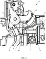
Fig. 2 illustrates the preferred embodiment of a section of a circuit breaker with a triggered trigger device wherein a latching point is released in a schematic side view. -
Fig. 3 illustrates the preferred embodiment of a section of a circuit breaker with a triggered trigger device wherein the push rod is in an end position in a schematic side view. -
Fig. 4 illustrates the preferred embodiment of a section of a circuit breaker with a triggered trigger device wherein the pushing contact collides with a stop in the frame of the circuit breaker in a schematic side view. -
Fig. 5 illustrates the preferred embodiment of a section of a circuit breaker with a triggered trigger device wherein the moving contact bounced back from the stop and collides with the push rod in a schematic side view. -
Fig. 6 illustrates a preferred embodiment of the push rod in a schematic side view. -
Fig. 7 illustrates the preferred embodiment of the push rod in an axonometric view. -
Fig. 1 to 7 illustrate at least a part of a preferred embodiment of atrigger device 1 for acircuit breaker 2 comprising apush rod 3 which is movably guided in apush rod housing 4 and acoil 5 which is substantially wrapped around said push rod - Further, a
circuit breaker 2 comprising atrigger device 1 is provided, the circuit breaker further comprising a movingcontact 9 which contacts afixed contact 10 in a closed position, a spring loadedlatch 7 to disconnect said movingcontact 9 from the fixedcontact 10, whereby thefirst stop surface 6 is adapted to trigger saidlatch 7 to mechanically disconnect the movingcontact 9 from thefixed contact 10 and thesecond stop surface 8 is adapted to contact said movingcontact 9 to prevent a backward movement of the movingcontact 9 in direction of said fixedcontact 10. - As a result, the
trigger device 1 fulfils the object and has the advantages that a safe operation of thecircuit breaker 2 is enabled and the lifespan of the movingcontact 9 and thefixed contact 10 is prolonged. Through the features, that thepush rod 3 comprises at least twodifferent stop surfaces first stop surface 6 is adapted to contact alatch 7 in order to trigger saidlatch 7 of thecircuit breaker 2 and at least onesecond stop surface 8 is adapted to contact a movingcontact 9 of thecircuit breaker 2, a backward movement of the movingcontact 9 in direction of the fixedcontact 10 is prevented and saidcontacts contact 9. - In general, a
circuit breaker 2 is an automatically operated electrical device which is designed to protect an electrical circuit from damage caused by excess current from an overload or short circuit. - In the following description, the
term circuit breaker 2 may comprehensively refer to a miniature circuit breaker (MCB) or to a residual current circuit breaker with overcurrent protection (RCBO) or to an arc fault detection device (AFDD). - It may be preferred, that the trip current for the
circuit breaker 2 is approximately 10 times higher than the rated current. For example, if the rated current is 16 A, it can be preferred, that the trip current is approximately 160 A. - Said
trigger device 1 comprises a movably guidedpush rod 3 which is particularly located in apush rod housing 4. Saidpush rod housing 4 could comprise a bearing element. Preferably, a ferromagnetic anchor is attached to a rear end of thenonmagnetic push rod 3. Saidpush rod 3 might be spring loaded. Acoil 5 is substantially wrapped around saidpush rod housing 4. In case of an overcurrent or short circuit, a magnetic field is formed via saidcoil 5 moving said ferromagnetic anchor and thus pushing saidpush rod 3 out of thepush rod housing 4 to a defined extent. Thepush rod 3 comprises at least twodifferent stop surfaces first stop surface 6 is adapted to contact alatch 7 in order to trigger saidlatch 7 of thecircuit breaker 2 and at least onesecond stop surface 8 is adapted to contact a movingcontact 9 of thecircuit breaker 2 to prevent a backward movement of the movingcontact 9 in direction of a fixedcontact 10. - Said
circuit breaker 2 comprises saidtrigger device 1 and further a spring loaded movingcontact 9 which contacts afixed contact 10 in a closed position, and alatch 7 to mechanically disconnect said movingcontact 9 from the fixedcontact 10. - According to a preferred embodiment, the
push rod 3 has a movement direction predefined by thepush rod housing 4 and that the at least onefirst stop surface 6 and the at least onesecond stop surface 8 are arranged staggered to each other in said movement direction. Preferably, saidpush rod 3 is linearly guided in thepush rod housing 4. - Hereby, the
push rod 3 can be manufactured in an easy and compact way. - According to another preferred embodiment, the
second stop surface 8 is located at a protrusion, which, in particular, protrudes the centre of thefirst stop surface 6, which is exemplarily shown infigs. 6 and 7 . With this preferred embodiment, thesecond stop surface 8 can easily be staggered from thefirst stop surface 6. In order to enable an especially easy way to manufacture thepush rod 3, it can be preferred, that thefirst stop surface 6 is particularly annular and surrounding the protrusion. This feature is also exemplarily shown infigs. 6 and 7 . - It can also be preferred, that the
latch 7 has a gap for the penetration of thesecond stop surface 8. Here, thesecond stop surface 8 penetrates said gap and contacts the movingcontact 9 to prevent the movingcontact 9 from bouncing in the direction of the fixedcontact 10. - Particularly, in an event of a short circuit, the
push rod 3 is pushed out of thepush rod housing 4 due to electromagnetic forces. Thepush rod 3 hits with its first stop surface 6 alatch 7, whereby said latch is loosened from its latching point and pushes away the movingcontact 9 from the fixedcontact 10 and thereby disconnecting saidcontacts Fig. 1 to 3 . Said movingcontact 9 is pushed against a stop within the frame of thecircuit breaker 2 and may swing back towards thefixed contact 10, which is exemplarily illustrated inFig. 4 . -
Fig. 5 exemplarily illustrates the contacting of the movingcontact 9 with thesecond stop surface 10 of thepush rod 3. Thepush rod 3 is held in its triggered position because the electromagnetic mechanism is still in operation because the emerging arc keeps the current still flowing through the coil. The movingcontact 9 swings towards thefixed contact 10 and contacts thesecond stop surface 10 of thepush rod 3 keeping thecontacts - While the present invention has been particularly shown and described with reference to exemplary embodiments thereof, it will be understood by those skilled in the art that various changes in form and details may be made therein without departing from the spirit and scope of the present invention as defined by the appended claims. The exemplary embodiments should be considered as descriptive only and not for purposes of limitation. Therefore, the scope of the present invention is not defined by the detailed description but by the appended claims.
- Hereinafter are principles for understanding and interpreting the actual disclosure.
- Features are usually introduced with an indefinite article "one, a, an". Unless otherwise stated in the context, therefore, "one, a, an" is not to be understood as a numeral.
- The conjunction "or" has to be interpreted as inclusive and not as exclusive, unless the context dictates otherwise. "A or B" also includes "A and B", where "A" and "B" represent random features.
- By means of an ordering number word, for example "first", "second" or "third", in particular a feature X or an object Y is distinguished in several embodiments, unless otherwise defined by the disclosure of the invention. In particular, a feature X or object Y with an ordering number word in a claim does not mean that an embodiment of the invention covered by this claim must have a further feature X or another object Y.
Claims (5)
- Trigger device (1) for a circuit breaker (2) comprising a push rod (3) which is movably guided in a push rod housing (4) and a coil (5) which is substantially wrapped around said push rod housing (4), characterised in, that the push rod (3) comprises at least two different stop surfaces (6, 8), whereby at least one first stop surface (6) is adapted to contact a latch (7) in order to trigger said latch (7) of the circuit breaker (2) and at least one second stop surface (8) is adapted to contact a moving contact (9) of the circuit breaker (2) to prevent a backward movement of the moving contact (9) in direction of a fixed contact (10).
- Trigger device (1) according to claim 1, characterised in, that the push rod (3) has a movement direction predefined by the push rod housing (4) and that the at least one first stop surface (6) and the at least one second stop surface (8) are arranged staggered to each other in said movement direction.
- Trigger device (1) according to claim 1 or 2, characterised in, that the second stop surface (8) is located at a protrusion, which, in particular, protrudes the centre of the first stop surface (6).
- Trigger device (1) according to claim 3, characterised in, that the first stop surface (6) is particularly annular and surrounding the protrusion.
- Circuit breaker (2) comprising a trigger device (1) according to any of the claims 1 to 3, a moving contact (9) which contacts a fixed contact (10) in a closedposition, a spring loaded latch (7) to disconnect said moving contact (9) from the fixed contact (10), characterised in, that the first stop surface (6) is adapted to trigger said latch (7) to mechanically disconnect the moving contact (9) from the fixed contact (10) and the second stop surface (8) is adapted to contact said moving contact (9) to prevent a backward movement of the moving contact (9) in direction of said fixed contact (10).
Applications Claiming Priority (1)
| Application Number | Priority Date | Filing Date | Title |
|---|---|---|---|
| GB2100722.4A GB2602968A (en) | 2021-01-20 | 2021-01-20 | Moving contact oscillating damper |
Publications (1)
| Publication Number | Publication Date |
|---|---|
| EP4033514A1 true EP4033514A1 (en) | 2022-07-27 |
Family
ID=74678903
Family Applications (1)
| Application Number | Title | Priority Date | Filing Date |
|---|---|---|---|
| EP22151091.0A Pending EP4033514A1 (en) | 2021-01-20 | 2022-01-12 | Moving contact oscillating damper |
Country Status (2)
| Country | Link |
|---|---|
| EP (1) | EP4033514A1 (en) |
| GB (1) | GB2602968A (en) |
Citations (6)
| Publication number | Priority date | Publication date | Assignee | Title |
|---|---|---|---|---|
| GB2040573A (en) * | 1979-02-07 | 1980-08-28 | Wolff H W | Improvements in electric circuit breakers |
| DE102004056279A1 (en) * | 2004-11-22 | 2006-05-24 | Abb Patent Gmbh | Protective switch with magnetic and thermal release for e.g. motor or circuit protection, is made from alloy with combined thermal- and magnetic shape memory |
| DE102006037225A1 (en) * | 2006-08-09 | 2008-02-14 | Siemens Ag | Switching unit |
| DE102006055936A1 (en) * | 2006-11-27 | 2008-06-12 | Siemens Ag | Line protection switch for switching arrangement, has contact element, which moves anchor from unmoved contact element and contact element is pushed away by exceeding threshold value by current flowing across current path |
| WO2009121696A1 (en) * | 2008-04-02 | 2009-10-08 | Siemens Aktiengesellschaft | Triggering mechanism |
| EP2680293A1 (en) * | 2012-06-25 | 2014-01-01 | Siemens Aktiengesellschaft | Release mechanism |
Family Cites Families (1)
| Publication number | Priority date | Publication date | Assignee | Title |
|---|---|---|---|---|
| JP5333253B2 (en) * | 2010-01-19 | 2013-11-06 | 三菱電機株式会社 | Circuit breaker |
-
2021
- 2021-01-20 GB GB2100722.4A patent/GB2602968A/en not_active Withdrawn
-
2022
- 2022-01-12 EP EP22151091.0A patent/EP4033514A1/en active Pending
Patent Citations (6)
| Publication number | Priority date | Publication date | Assignee | Title |
|---|---|---|---|---|
| GB2040573A (en) * | 1979-02-07 | 1980-08-28 | Wolff H W | Improvements in electric circuit breakers |
| DE102004056279A1 (en) * | 2004-11-22 | 2006-05-24 | Abb Patent Gmbh | Protective switch with magnetic and thermal release for e.g. motor or circuit protection, is made from alloy with combined thermal- and magnetic shape memory |
| DE102006037225A1 (en) * | 2006-08-09 | 2008-02-14 | Siemens Ag | Switching unit |
| DE102006055936A1 (en) * | 2006-11-27 | 2008-06-12 | Siemens Ag | Line protection switch for switching arrangement, has contact element, which moves anchor from unmoved contact element and contact element is pushed away by exceeding threshold value by current flowing across current path |
| WO2009121696A1 (en) * | 2008-04-02 | 2009-10-08 | Siemens Aktiengesellschaft | Triggering mechanism |
| EP2680293A1 (en) * | 2012-06-25 | 2014-01-01 | Siemens Aktiengesellschaft | Release mechanism |
Also Published As
| Publication number | Publication date |
|---|---|
| GB2602968A (en) | 2022-07-27 |
| GB202100722D0 (en) | 2021-03-03 |
Similar Documents
| Publication | Publication Date | Title |
|---|---|---|
| US5444424A (en) | Circuit breaker trip solenoid having over-travel mechanism | |
| US5089796A (en) | Earth leakage trip indicator | |
| US5933063A (en) | Ground fault circuit interrupter | |
| KR20070093498A (en) | Miniature Circuit Breaker with Overload and Short Circuit Protection | |
| US8183964B2 (en) | Current trip unit for circuit breaker | |
| JP4967602B2 (en) | Earth leakage trip device for earth leakage breaker | |
| JP2735384B2 (en) | Circuit breaker | |
| KR20120071937A (en) | Trip unit for molded case circuit breaker | |
| US3938065A (en) | Push-button operated bipolar faulty current protective switch | |
| GB2602968A (en) | Moving contact oscillating damper | |
| US6628185B2 (en) | Blade assembly for a circuit breaker | |
| CN101546657B (en) | Service switching device with double-break contacts | |
| CN103794421B (en) | Electric circuit protection equipment and the flux shift unit for electric circuit protection equipment | |
| KR20180065483A (en) | Instantaneous trip device for circuit breaker | |
| KR200418667Y1 (en) | Miniature Circuit Breaker with Overload and Short Circuit Protection | |
| US8149075B2 (en) | Plastic cradle | |
| JP5215268B2 (en) | Breaker | |
| US20070205852A1 (en) | Magnetic trip mechanism including a plunger member engaging a support structure, and circuit breaker including the same | |
| JP7508180B2 (en) | Release device | |
| CN103515160B (en) | trigger mechanism | |
| KR200212855Y1 (en) | Electronic trip coil mechanism of circuit breaker | |
| KR102085222B1 (en) | Instantaneous Trip Apparatus and Circuit Breaker Having the Same | |
| KR200463757Y1 (en) | Molded case circuit breaker | |
| KR20170122664A (en) | Circuit breaker having a framed finger area | |
| KR20210123883A (en) | Earth Leakage Trip Device |
Legal Events
| Date | Code | Title | Description |
|---|---|---|---|
| PUAI | Public reference made under article 153(3) epc to a published international application that has entered the european phase |
Free format text: ORIGINAL CODE: 0009012 |
|
| STAA | Information on the status of an ep patent application or granted ep patent |
Free format text: STATUS: THE APPLICATION HAS BEEN PUBLISHED |
|
| AK | Designated contracting states |
Kind code of ref document: A1 Designated state(s): AL AT BE BG CH CY CZ DE DK EE ES FI FR GB GR HR HU IE IS IT LI LT LU LV MC MK MT NL NO PL PT RO RS SE SI SK SM TR |
|
| STAA | Information on the status of an ep patent application or granted ep patent |
Free format text: STATUS: REQUEST FOR EXAMINATION WAS MADE |
|
| 17P | Request for examination filed |
Effective date: 20230125 |
|
| RBV | Designated contracting states (corrected) |
Designated state(s): AL AT BE BG CH CY CZ DE DK EE ES FI FR GB GR HR HU IE IS IT LI LT LU LV MC MK MT NL NO PL PT RO RS SE SI SK SM TR |
|
| P01 | Opt-out of the competence of the unified patent court (upc) registered |
Effective date: 20230521 |
|
| STAA | Information on the status of an ep patent application or granted ep patent |
Free format text: STATUS: EXAMINATION IS IN PROGRESS |
|
| 17Q | First examination report despatched |
Effective date: 20250707 |