EP4033480A1 - Display unit with backlight driver - Google Patents
Display unit with backlight driver Download PDFInfo
- Publication number
- EP4033480A1 EP4033480A1 EP21170249.3A EP21170249A EP4033480A1 EP 4033480 A1 EP4033480 A1 EP 4033480A1 EP 21170249 A EP21170249 A EP 21170249A EP 4033480 A1 EP4033480 A1 EP 4033480A1
- Authority
- EP
- European Patent Office
- Prior art keywords
- chains
- light sources
- chn
- display unit
- backlight
- Prior art date
- Legal status (The legal status is an assumption and is not a legal conclusion. Google has not performed a legal analysis and makes no representation as to the accuracy of the status listed.)
- Withdrawn
Links
Images



Classifications
-
- G—PHYSICS
- G09—EDUCATION; CRYPTOGRAPHY; DISPLAY; ADVERTISING; SEALS
- G09G—ARRANGEMENTS OR CIRCUITS FOR CONTROL OF INDICATING DEVICES USING STATIC MEANS TO PRESENT VARIABLE INFORMATION
- G09G3/00—Control arrangements or circuits, of interest only in connection with visual indicators other than cathode-ray tubes
- G09G3/001—Control arrangements or circuits, of interest only in connection with visual indicators other than cathode-ray tubes using specific devices not provided for in groups G09G3/02 - G09G3/36, e.g. using an intermediate record carrier such as a film slide; Projection systems; Display of non-alphanumerical information, solely or in combination with alphanumerical information, e.g. digital display on projected diapositive as background
- G09G3/002—Control arrangements or circuits, of interest only in connection with visual indicators other than cathode-ray tubes using specific devices not provided for in groups G09G3/02 - G09G3/36, e.g. using an intermediate record carrier such as a film slide; Projection systems; Display of non-alphanumerical information, solely or in combination with alphanumerical information, e.g. digital display on projected diapositive as background to project the image of a two-dimensional display, such as an array of light emitting or modulating elements or a CRT
-
- G—PHYSICS
- G09—EDUCATION; CRYPTOGRAPHY; DISPLAY; ADVERTISING; SEALS
- G09G—ARRANGEMENTS OR CIRCUITS FOR CONTROL OF INDICATING DEVICES USING STATIC MEANS TO PRESENT VARIABLE INFORMATION
- G09G3/00—Control arrangements or circuits, of interest only in connection with visual indicators other than cathode-ray tubes
- G09G3/20—Control arrangements or circuits, of interest only in connection with visual indicators other than cathode-ray tubes for presentation of an assembly of a number of characters, e.g. a page, by composing the assembly by combination of individual elements arranged in a matrix no fixed position being assigned to or needed to be assigned to the individual characters or partial characters
- G09G3/34—Control arrangements or circuits, of interest only in connection with visual indicators other than cathode-ray tubes for presentation of an assembly of a number of characters, e.g. a page, by composing the assembly by combination of individual elements arranged in a matrix no fixed position being assigned to or needed to be assigned to the individual characters or partial characters by control of light from an independent source
- G09G3/3406—Control of illumination source
- G09G3/342—Control of illumination source using several illumination sources separately controlled corresponding to different display panel areas, e.g. along one dimension such as lines
-
- H—ELECTRICITY
- H05—ELECTRIC TECHNIQUES NOT OTHERWISE PROVIDED FOR
- H05B—ELECTRIC HEATING; ELECTRIC LIGHT SOURCES NOT OTHERWISE PROVIDED FOR; CIRCUIT ARRANGEMENTS FOR ELECTRIC LIGHT SOURCES, IN GENERAL
- H05B45/00—Circuit arrangements for operating light-emitting diodes [LED]
- H05B45/30—Driver circuits
- H05B45/34—Voltage stabilisation; Maintaining constant voltage
-
- H—ELECTRICITY
- H05—ELECTRIC TECHNIQUES NOT OTHERWISE PROVIDED FOR
- H05B—ELECTRIC HEATING; ELECTRIC LIGHT SOURCES NOT OTHERWISE PROVIDED FOR; CIRCUIT ARRANGEMENTS FOR ELECTRIC LIGHT SOURCES, IN GENERAL
- H05B45/00—Circuit arrangements for operating light-emitting diodes [LED]
- H05B45/50—Circuit arrangements for operating light-emitting diodes [LED] responsive to malfunctions or undesirable behaviour of LEDs; responsive to LED life; Protective circuits
- H05B45/56—Circuit arrangements for operating light-emitting diodes [LED] responsive to malfunctions or undesirable behaviour of LEDs; responsive to LED life; Protective circuits involving measures to prevent abnormal temperature of the LEDs
-
- H—ELECTRICITY
- H05—ELECTRIC TECHNIQUES NOT OTHERWISE PROVIDED FOR
- H05B—ELECTRIC HEATING; ELECTRIC LIGHT SOURCES NOT OTHERWISE PROVIDED FOR; CIRCUIT ARRANGEMENTS FOR ELECTRIC LIGHT SOURCES, IN GENERAL
- H05B47/00—Circuit arrangements for operating light sources in general, i.e. where the type of light source is not relevant
- H05B47/20—Responsive to malfunctions or to light source life; for protection
- H05B47/28—Circuit arrangements for protecting against abnormal temperature
-
- G—PHYSICS
- G09—EDUCATION; CRYPTOGRAPHY; DISPLAY; ADVERTISING; SEALS
- G09G—ARRANGEMENTS OR CIRCUITS FOR CONTROL OF INDICATING DEVICES USING STATIC MEANS TO PRESENT VARIABLE INFORMATION
- G09G2320/00—Control of display operating conditions
- G09G2320/02—Improving the quality of display appearance
- G09G2320/0247—Flicker reduction other than flicker reduction circuits used for single beam cathode-ray tubes
-
- G—PHYSICS
- G09—EDUCATION; CRYPTOGRAPHY; DISPLAY; ADVERTISING; SEALS
- G09G—ARRANGEMENTS OR CIRCUITS FOR CONTROL OF INDICATING DEVICES USING STATIC MEANS TO PRESENT VARIABLE INFORMATION
- G09G2320/00—Control of display operating conditions
- G09G2320/06—Adjustment of display parameters
- G09G2320/0626—Adjustment of display parameters for control of overall brightness
- G09G2320/064—Adjustment of display parameters for control of overall brightness by time modulation of the brightness of the illumination source
-
- G—PHYSICS
- G09—EDUCATION; CRYPTOGRAPHY; DISPLAY; ADVERTISING; SEALS
- G09G—ARRANGEMENTS OR CIRCUITS FOR CONTROL OF INDICATING DEVICES USING STATIC MEANS TO PRESENT VARIABLE INFORMATION
- G09G2320/00—Control of display operating conditions
- G09G2320/06—Adjustment of display parameters
- G09G2320/0626—Adjustment of display parameters for control of overall brightness
- G09G2320/0653—Controlling or limiting the speed of brightness adjustment of the illumination source
-
- G—PHYSICS
- G09—EDUCATION; CRYPTOGRAPHY; DISPLAY; ADVERTISING; SEALS
- G09G—ARRANGEMENTS OR CIRCUITS FOR CONTROL OF INDICATING DEVICES USING STATIC MEANS TO PRESENT VARIABLE INFORMATION
- G09G2330/00—Aspects of power supply; Aspects of display protection and defect management
- G09G2330/02—Details of power systems and of start or stop of display operation
- G09G2330/021—Power management, e.g. power saving
-
- G—PHYSICS
- G09—EDUCATION; CRYPTOGRAPHY; DISPLAY; ADVERTISING; SEALS
- G09G—ARRANGEMENTS OR CIRCUITS FOR CONTROL OF INDICATING DEVICES USING STATIC MEANS TO PRESENT VARIABLE INFORMATION
- G09G2330/00—Aspects of power supply; Aspects of display protection and defect management
- G09G2330/04—Display protection
- G09G2330/045—Protection against panel overheating
-
- G—PHYSICS
- G09—EDUCATION; CRYPTOGRAPHY; DISPLAY; ADVERTISING; SEALS
- G09G—ARRANGEMENTS OR CIRCUITS FOR CONTROL OF INDICATING DEVICES USING STATIC MEANS TO PRESENT VARIABLE INFORMATION
- G09G2380/00—Specific applications
- G09G2380/10—Automotive applications
Definitions
- the invention is directed to a display unit with backlight driver like display units used in a central display of a vehicle or any other kind of displays requiring a backlight with backlight driver, and a head-up display unit with a respective display unit.
- the backlight preferably is provided with an LED illumination circuit.
- the invention suggests forward voltage equalization with Zener diode on asymmetric LED chains, especially for use as backlight for a display.
- a lighting unit for a display unit is shown in US 2010/102 733 A1 .
- This document shows an LED light string.
- a chain of LEDs is arranged in line with a parallel arrangement of Zener diode and resistor. It is using a Zener diode as an overvoltage protection for an LED string directly connected to AC power.
- the resistor is used to limit the LED current and it is calculated based on LED count and acceptable LED current.
- a single chain of LEDs is shown.
- the present invention refers to an adaptation of brightness that might be necessary in case several chains of LEDs are used.
- the present inventio also refers to several chains having different number of LEDs.
- EP 890 894 A1 shows an incandescent bulb luminance matching LED circuit. It is using a Zener diode as a bypass to the current set resistor for higher voltages.
- the present invention refers to adaptation of the voltage seen by a backlight driver and has nothing to do with brightness adaptation since that is already achieved by the backlight driver current sink.
- US 2015/015 149 A1 is directed to an LED control method and apparatus. Therein, several LEDs are arranged in parallel with a Zener diode. This is a classic scheme for low cost constant current driving of parallel LEDs with a variable input voltage. It has nothing to do with LED chain voltage equalization. It just establishes a constant voltage across multiple LEDs, and a current is set through each individual resistor.
- the present invention is directed to equalization which the inventor found being necessary only if a backlight driver is used. None of these documents is targeting voltage equalization between LED chains, found by the inventor to be required by a backlight driver mechanism of a constant current sink.
- the light sources might be turned on intermittently, or the light sources are driven with variable power. Both of these control methods may also be combined, a so-called hybrid dimming. The method chosen depends, amongst others, on the type of light source.
- Such display unit comprises a display for creating an image to be displayed to a viewer. Further, a backlight unit with backlight driver for the display and at least one chain of light sources driven by the backlight driver. It further comprises an equalisation circuit arranged in series with one of the chains of light sources, while at least one other chain is nor provided with an equalisation circuit.
- the equalisation circuit comprises a Zener diode having a Zener Diode reverse voltage that matches the chain's forward voltage difference. This has as one advantage that it makes possible to use asymmetric chains of light sources which is desirable for certain applications, especially for the backlight unit of a head-up display system.
- the chains may be asymmetric in that they contain different numbers of light sources, different types of light sources, or differ from each other in any other characteristic that makes them having forward voltages differently from each other.
- This circuit according to the invention protects the backlight driver from overheating by shifting power caused by a voltage difference between different chains of LED light sources.
- the equalisation circuit further comprises a resistor arranged in parallel to the Zener diode.
- a resistor arranged in parallel to the Zener diode.
- LEDs are used as light sources, as the suggested solution fits well to the characteristic behaviour of LEDs.
- the backlight driving unit is provided to adjust both, the ON time for a chain of light sources as well as a current amplitude for this chain of light sources.
- This has the advantage to make possible hybrid dimming which provides more flexibility. It allows to choose an on time frequency so as to avoid frequencies that give a bad impression to an observer of the virtual image, for example caused by flickering in case of an on time frequency that is rather low. It further allows to choose a current amplitude to be below a critical maximum current. Driving the light sources with such critical maximum current or above reduces lifetime of light sources or even may cause immediate defects. Using these or other dimming methods in combination is referred to here as hybrid dimming.
- the backlight driving unit is a constant current backlight driving unit having a common anode for several chains of light sources.
- the backlight driver unit is a commonly used component, designed to drive chains of light sources, wherein the number of light sources of the chains must be the same for each of the chains.
- the equalisation circuit according to the invention allows to use such commonly use component even with chains of light sources having different numbers of light sources. This allows to use efficient components and, at the same time, reaching a high-quality lighting result.
- a lighting unit according to the invention with backlight driver and at least two chains of light sources driven by the backlight driver comprises an equalisation circuit arranged in series with a chain of light sources, the different chains having different light source counts.
- the equalisation circuit comprises a Zener diode having a Zener Diode reverse voltage that matches the chain's forward voltage difference.
- a display unit preferably has chains of light sources where each of the chains of light sources has a forward voltage, and an equalisation circuit being arranged in series with all chains except for those of the chains for which the forward voltage equals the maximum forward voltage of all chains.
- a head-up display unit is preferably provided with a display unit according to the invention.
- a display unit is described in the following as being used in a head-up display.
- a display unit according to the invention is also applicable to other display systems that are not described here in detail but that are known to a skilled person.
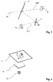
- Fig. 1 shows a sketch of a state-of-the-art head-up display unit 1 for a motor vehicle.
- the head-up display unit 1 has a picture generating unit 10, an optical unit 14 and a mirror unit 2.
- a beam SB1 emanates from a liquid crystal display 11 of the picture generating unit 10 and is reflected by a folding mirror 21 onto a curved mirror 22, which reflects it in the direction of the mirror unit 2.
- the mirror unit 2 is shown here as a windscreen 20 of the motor vehicle. From there, the beam SB2 is directed towards the eye 3 of an observer.
- the observer sees a virtual image VB, which is located outside the vehicle above the bonnet or even in front of the vehicle. Due to the interaction of the optical unit 14 and the mirror unit 2, the virtual image VB is an enlarged representation of the image displayed by the display 11. Here a symbolic speed limit, the current vehicle speed and navigation instructions are displayed. As long as the eye 3 is inside a so-called eyebox 4 indicated by a rectangle, all elements of the virtual image VB are visible to the eye 3. If the eye 3 is located outside the eyebox 4, the virtual image VB is only partially or not at all visible to the viewer. The larger the eyebox 4 is, the less restricted the viewer is in his choice of the seating position.
- the curvature of the curved mirror 22 is adapted to the curvature of the windscreen 20 and ensures that the image distortion is stable over the entire eyebox 4.
- the curved mirror 22 is rotatably supported by a bearing 221. By rotating the curved mirror 22, it is possible to shift the eyebox 4 and thus to adjust the position of the eyebox 4 to the position of the eye 3.
- the folding mirror 21 ensures that the distance travelled by the beam SB1 between the display 11 and the curved mirror 22 is long, while, at the same time, the optical unit 14 remains compact.
- the optical unit 14 and the picture generating unit 10 are accommodated in a housing assembly 15 and separated from the environment by a transparent cover 23. The optical elements of the optical unit 14 are thus protected, for example, against dust inside the vehicle.
- An optical foil or polarizer 24 can be located on the cover 23.
- the display 11 typically emits polarized light and the mirror unit 2 acts like an analyser.
- the purpose of the polarizer, or glare trap, 24 is to influence the amount of sunlight entering the head-up display.
- a light trap 25 serves to securely shield light reflected from the road or to block light from different sources placed at car height level so that it does not reach the observer. In addition to sunlight SL coming from the sun 5, also light from another source of interference might reach the display 11.
- Fig. 2 shows a simplified sketch similar to Fig.1 .
- a Head-up Display also referred to as HUD, is used to place information in the field of view of the user in such a way as to appear integrated in the surrounding environment. The intention is to provide the information in a way that does not require the user to significantly change the eye gaze direction and/or focus distance.
- HUDs are of particular importance in avionics and the automotive fields where they allow the vehicle's operator to glance important aspects of the trip without taking the eyes away from the path ahead. For this purpose, state of the art HUDs are required to deliver this information clearly discernible, independent of the ambient light level.
- One of the preferred architectures for HUDs comprises an image generating unit 10, an intermediate mirror, the folding mirror 21, and a transparent HUD screen, the mirror unit 2.
- this diagram should be understood as one of the possible embodiments and should not be regarded as restrictive to the present invention.
- the picture generating unit 10 is responsible for producing the symbols that shall be visible to the end user.
- the optical system from the depicted embodiment, consisting of the folding mirror 21 and the HUD screen, mirror unit 2, is designed in such a way as to produce a virtual image VB from the images generated by the generator unit 10 that are magnified and seen at a certain distance in front of the mirror unit 2.
- the mirror unit 2 is formed with the aid of an optically clear medium in order to not impede the visibility of the end user's environment.
- This mirror unit 2 may be a dedicated component, typically called combiner, or it may be formed as a region on the vehicle's windshield.
- Fig. 3 shows the picture generating unit 10 in a simplified diagrammatic view.
- a light source 13 illuminates, via a light control structure 16, a liquid crystal display 11 on which an image is displayed.
- a transmissive liquid crystal display 11, also referred to as LCD, is shown here.
- LCD transmissive liquid crystal display
- other display technologies known to the skilled person such as other transmissive displays that require a backlight driver may be applied here as well.
- Fig. 4 shows a known head-up display unit 1 with backlight driver BL.
- the backlight driver BL is connected to an input voltage V IN of the power supply.
- Input current I IN flows to input In of the backlight driver BL.
- An of the backlight driver BL output voltage V OUT to drive a light source LS is provided.
- Output current I OUT flows through the light source LS and back to cathode input Cat of the backlight driver BL.
- the current regulation together with highest possible efficiency of the backlight driver BL is achieved by adjusting the output voltage V OUT permanently so that the current sink from Cathode Cat maintains its minimum headroom voltage required to properly work.
- Fig. 5 shows circuitry of a head-up display unit 1 according to the invention.
- the backlight driver BL has n Cathodes Cat1, ... Catn, each connected to a respective chain CH1, ... , CHn of light sources. Respective electric currents I LED1 , ... I LEDN flow through chains CH1,...,CHn. There are respective forward voltages VFWn for the chains CHn.
- Each chain CH1, ..., CHn of light sources comprises a number NLS1, ... , NLSn of light sources. This number is indicated for each chain in the drawing. At least one of the numbers NLSx differs from the other numbers NLS1, ... , NLS(x-1), NLS(x+1), ...
- the equalisation circuit 12-n comprises a Zener diode Zn in parallel arrangement with a resistor Rn.
- the reverse voltage V REVn of the Zener diode Zn matches the forward voltage of the light sources of the respective chain CHn.
- these light sources are light emitting diodes.
- the solution according to the invention provides for boost output voltage rise until it can ensure at least minimum backlight driver headroom voltage as specified in its datasheet for the highest forward voltage chain.
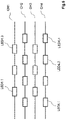
- Fig. 6 shows an exemplary arrangement of asymmetric chains CH1,...,CH4 of light sources LEDn,m.
- Chain CH1 as shown here consists of three light sources LED1,1, LED1,2 and LED1,3.
- Chain CH3 also has three light sources, the other two chains have four light sources each.
- the light sources LEDn,m are flat light emitting diodes and are thus not shown with a symbol but with an indication of their physical shape.
- an equalization circuit 12-1, 12-3 is required for chains CH1 and CH3 to match the forward voltages VFW2 and VFW4 of chain CH2 and chain CH4, respectively, which both equal the maximum forward voltage VFWmax in this example.
- LED Light Emitting Diodes
- LED forward voltage equalization in backlight drivers BL for displays is usually done by series resistors calculated for the target forward current. Another option is not to equalize them and to leave the equalization for the LED driver to perform.
- a series resistor solution can be precisely calculated only for a certain LED current, which prevents usage of hybrid dimming (adjusting both LED ON time and LED current amplitude). This option is suitable only for constant current driving that is not adjusted after production, which limits the brightness calibration via current adjustment. The option of not equalizing the LED total forward voltage would simply shift the power dissipation of the missing LED to the backlight driver, which usually cannot sustain such high power in case of high current LED driving.
- the solution according to the invention seeks to shift power dissipation away from a backlight driver and to allow LED current adjustment for both calibration and hybrid dimming.
- the anode voltage V OUT is common to all LED chains CH1,...,CHn and adjusted so that the backlight driver BL will have the smallest power dissipation on the current sinks. Due to this topology, it is necessary to have the same amount of LEDs per chain, or at least a similar voltage, if the solution according to the invention would not be used.
- Forward voltage equalization on asymmetric LED chains CH1,...,CHn can be done with a Zener diode Zn with reverse voltage like LED forward voltage. Taking white LED' s as an example with typical 3V forward voltage, a Zener diode Zn with 3V reverse voltage at LED current used should be used. This simple solution works best if the LED forward current is always enough so that the Zener diode Zn is conducting (minimum reverse current for breakdown is achieved).
- the resistor Rn Even if the Zener diode Zn does not have enough reverse current to conduct, the resistor Rn will allow current flow. If the resistor Rn is designed for maximum power, at small LED current the voltage drop will not be equal to one LED forward voltage, but for this low power, the backlight driver BL can afford this increase in power dissipation which will be smaller than high current power dissipation.
- the solution according to the invention can be used on any constant current backlight drivers with common anode for all lighting applications that have asymmetric LED count per chain.
- the backlight driver BL with multiple chains with asymmetric LED count NLS per chain is represented together with an equalization circuit 12.
- the parallel resistor Rn with the Zener diode Zn can be calculated to different values depending on the application use case. By modifying resistor Rn value, a proper power distribution balancing can be performed between Zener diode Zn and resistor Rn so that proper thermal behaviour is achieved.
Landscapes
- Engineering & Computer Science (AREA)
- Physics & Mathematics (AREA)
- Computer Hardware Design (AREA)
- General Physics & Mathematics (AREA)
- Theoretical Computer Science (AREA)
- Control Of Indicators Other Than Cathode Ray Tubes (AREA)
Abstract
Description
- The invention is directed to a display unit with backlight driver like display units used in a central display of a vehicle or any other kind of displays requiring a backlight with backlight driver, and a head-up display unit with a respective display unit. The backlight preferably is provided with an LED illumination circuit. The invention suggests forward voltage equalization with Zener diode on asymmetric LED chains, especially for use as backlight for a display.
- A lighting unit for a display unit is shown in
US 2010/102 733 A1 . This document shows an LED light string. A chain of LEDs is arranged in line with a parallel arrangement of Zener diode and resistor. It is using a Zener diode as an overvoltage protection for an LED string directly connected to AC power. The resistor is used to limit the LED current and it is calculated based on LED count and acceptable LED current. A single chain of LEDs is shown. The present invention refers to an adaptation of brightness that might be necessary in case several chains of LEDs are used. The present inventio also refers to several chains having different number of LEDs. -
EP 890 894 A1 -
US 2015/015 149 A1 is directed to an LED control method and apparatus. Therein, several LEDs are arranged in parallel with a Zener diode. This is a classic scheme for low cost constant current driving of parallel LEDs with a variable input voltage. It has nothing to do with LED chain voltage equalization. It just establishes a constant voltage across multiple LEDs, and a current is set through each individual resistor. The present invention is directed to equalization which the inventor found being necessary only if a backlight driver is used. None of these documents is targeting voltage equalization between LED chains, found by the inventor to be required by a backlight driver mechanism of a constant current sink. - There are different methods to adapt the output of the light sources. For example, the light sources might be turned on intermittently, or the light sources are driven with variable power. Both of these control methods may also be combined, a so-called hybrid dimming. The method chosen depends, amongst others, on the type of light source.
- It is desired to find an appropriate and cost-efficient solution for a display unit output brightness control.
- This is achieved by a display unit according to
claim 1. Such display unit comprises a display for creating an image to be displayed to a viewer. Further, a backlight unit with backlight driver for the display and at least one chain of light sources driven by the backlight driver. It further comprises an equalisation circuit arranged in series with one of the chains of light sources, while at least one other chain is nor provided with an equalisation circuit. The equalisation circuit comprises a Zener diode having a Zener Diode reverse voltage that matches the chain's forward voltage difference. This has as one advantage that it makes possible to use asymmetric chains of light sources which is desirable for certain applications, especially for the backlight unit of a head-up display system. The chains may be asymmetric in that they contain different numbers of light sources, different types of light sources, or differ from each other in any other characteristic that makes them having forward voltages differently from each other. This circuit according to the invention protects the backlight driver from overheating by shifting power caused by a voltage difference between different chains of LED light sources. - Advantageously, the equalisation circuit further comprises a resistor arranged in parallel to the Zener diode. This allows for low current injection through the respective chain of light sources without the risk of leaving such chain open. Preferably, LEDs are used as light sources, as the suggested solution fits well to the characteristic behaviour of LEDs.
- Advantageously the backlight driving unit is provided to adjust both, the ON time for a chain of light sources as well as a current amplitude for this chain of light sources. This has the advantage to make possible hybrid dimming which provides more flexibility. It allows to choose an on time frequency so as to avoid frequencies that give a bad impression to an observer of the virtual image, for example caused by flickering in case of an on time frequency that is rather low. It further allows to choose a current amplitude to be below a critical maximum current. Driving the light sources with such critical maximum current or above reduces lifetime of light sources or even may cause immediate defects. Using these or other dimming methods in combination is referred to here as hybrid dimming.
- The backlight driving unit is a constant current backlight driving unit having a common anode for several chains of light sources. The backlight driver unit is a commonly used component, designed to drive chains of light sources, wherein the number of light sources of the chains must be the same for each of the chains. The equalisation circuit according to the invention allows to use such commonly use component even with chains of light sources having different numbers of light sources. This allows to use efficient components and, at the same time, reaching a high-quality lighting result.
- A lighting unit according to the invention with backlight driver and at least two chains of light sources driven by the backlight driver comprises an equalisation circuit arranged in series with a chain of light sources, the different chains having different light source counts. The equalisation circuit comprises a Zener diode having a Zener Diode reverse voltage that matches the chain's forward voltage difference. Such lighting unit has similar advantages as described above with regard to a head-up display system's backlight unit. Similar additional features as described above lead to similar advantages as described above, even though these are not mentioned here in detail.
- A display unit according to the invention preferably has chains of light sources where each of the chains of light sources has a forward voltage, and an equalisation circuit being arranged in series with all chains except for those of the chains for which the forward voltage equals the maximum forward voltage of all chains. This has the advantage that an optimum adaptation of all chains is reached, while at the same time low power loss and low risk for the backlight driver come along with high flexibility for selection of number and/or type of light sources used for all chains, where all chains might be designed differently from each other.
- A head-up display unit is preferably provided with a display unit according to the invention.
- Further features of the present invention will become apparent from the following description and the appended claims in conjunction with the figures.
-
- Fig. 1
- state-of-the-art head-up display unit;
- Fig. 2
- simplified sketch similar to
Fig.1 ; - Fig. 3
- picture generating unit;
- Fig. 4
- backlight driver;
- Fig. 5
- circuitry of a display unit according to the invention;
- Fig. 6
- asymmetric chains of light sources.
- For a better understanding of the principles of the present invention, embodiments of the invention will be explained in more detail below with reference to the figures. Like reference numerals are used in the figures for the same or equivalent elements and are not necessarily described again for each figure. It is to be understood that the invention is not limited to the illustrated embodiments and that the features described may also be combined or modified without departing from the scope of the invention as defined in the appended claims.
- As an example, a display unit is described in the following as being used in a head-up display. Of course, a display unit according to the invention is also applicable to other display systems that are not described here in detail but that are known to a skilled person.
-
Fig. 1 shows a sketch of a state-of-the-art head-updisplay unit 1 for a motor vehicle. The head-updisplay unit 1 has apicture generating unit 10, anoptical unit 14 and amirror unit 2. A beam SB1 emanates from aliquid crystal display 11 of thepicture generating unit 10 and is reflected by afolding mirror 21 onto acurved mirror 22, which reflects it in the direction of themirror unit 2. Themirror unit 2 is shown here as a windscreen 20 of the motor vehicle. From there, the beam SB2 is directed towards the eye 3 of an observer. - The observer sees a virtual image VB, which is located outside the vehicle above the bonnet or even in front of the vehicle. Due to the interaction of the
optical unit 14 and themirror unit 2, the virtual image VB is an enlarged representation of the image displayed by thedisplay 11. Here a symbolic speed limit, the current vehicle speed and navigation instructions are displayed. As long as the eye 3 is inside a so-called eyebox 4 indicated by a rectangle, all elements of the virtual image VB are visible to the eye 3. If the eye 3 is located outside the eyebox 4, the virtual image VB is only partially or not at all visible to the viewer. The larger the eyebox 4 is, the less restricted the viewer is in his choice of the seating position. - The curvature of the
curved mirror 22 is adapted to the curvature of the windscreen 20 and ensures that the image distortion is stable over the entire eyebox 4. Thecurved mirror 22 is rotatably supported by abearing 221. By rotating thecurved mirror 22, it is possible to shift the eyebox 4 and thus to adjust the position of the eyebox 4 to the position of the eye 3. Thefolding mirror 21 ensures that the distance travelled by the beam SB1 between thedisplay 11 and thecurved mirror 22 is long, while, at the same time, theoptical unit 14 remains compact. Theoptical unit 14 and thepicture generating unit 10 are accommodated in ahousing assembly 15 and separated from the environment by atransparent cover 23. The optical elements of theoptical unit 14 are thus protected, for example, against dust inside the vehicle. An optical foil orpolarizer 24 can be located on thecover 23. Thedisplay 11 typically emits polarized light and themirror unit 2 acts like an analyser. The purpose of the polarizer, or glare trap, 24 is to influence the amount of sunlight entering the head-up display. Alight trap 25 serves to securely shield light reflected from the road or to block light from different sources placed at car height level so that it does not reach the observer. In addition to sunlight SL coming from the sun 5, also light from another source of interference might reach thedisplay 11. -
Fig. 2 shows a simplified sketch similar toFig.1 . Here, only a single mirror, foldingmirror 21, is shown for simplicity. A Head-up Display, also referred to as HUD, is used to place information in the field of view of the user in such a way as to appear integrated in the surrounding environment. The intention is to provide the information in a way that does not require the user to significantly change the eye gaze direction and/or focus distance. HUDs are of particular importance in avionics and the automotive fields where they allow the vehicle's operator to glance important aspects of the trip without taking the eyes away from the path ahead. For this purpose, state of the art HUDs are required to deliver this information clearly discernible, independent of the ambient light level. This translates in high brightness requirements in excess of 10,000 cd/m2 or even 15,000 cd/m2 for the virtual image produced by the HUD. One of the preferred architectures for HUDs, as depicted in the figure, comprises animage generating unit 10, an intermediate mirror, thefolding mirror 21, and a transparent HUD screen, themirror unit 2. As a note, this diagram should be understood as one of the possible embodiments and should not be regarded as restrictive to the present invention. - The
picture generating unit 10 is responsible for producing the symbols that shall be visible to the end user. The optical system from the depicted embodiment, consisting of thefolding mirror 21 and the HUD screen,mirror unit 2, is designed in such a way as to produce a virtual image VB from the images generated by thegenerator unit 10 that are magnified and seen at a certain distance in front of themirror unit 2. As a note, themirror unit 2 is formed with the aid of an optically clear medium in order to not impede the visibility of the end user's environment. Thismirror unit 2 may be a dedicated component, typically called combiner, or it may be formed as a region on the vehicle's windshield. -
Fig. 3 shows thepicture generating unit 10 in a simplified diagrammatic view. Alight source 13 illuminates, via alight control structure 16, aliquid crystal display 11 on which an image is displayed. A transmissiveliquid crystal display 11, also referred to as LCD, is shown here. However, also other display technologies known to the skilled person, such as other transmissive displays that require a backlight driver may be applied here as well. -
Fig. 4 shows a known head-updisplay unit 1 with backlight driver BL. The backlight driver BL is connected to an input voltage VIN of the power supply. Input current IIN flows to input In of the backlight driver BL. At an anode An of the backlight driver BL output voltage VOUT to drive a light source LS is provided. Output current IOUT flows through the light source LS and back to cathode input Cat of the backlight driver BL. The current regulation together with highest possible efficiency of the backlight driver BL is achieved by adjusting the output voltage VOUT permanently so that the current sink from Cathode Cat maintains its minimum headroom voltage required to properly work. If several additional light sources shall be used, these can all be connected to the same anode An with output current IOUT sinked by the backlight driver BL, but use different cathodes Catn with respective currents ILED1, ... ILEDn, not shown here. In case of multiple chains CHn connected, which is not shown here, the chain CHx with the highest forward voltage VFWx = VFWmax of all chains CHn will establish the output voltage Vout so that on its cathode Catx it will have the minimum headroom voltage, and the rest of the chains CHn will have the headroom plus the respective voltage difference. If this voltage difference is increased, e.g. by means of different LED count or different LED parameters, more power dissipation will occur on the backlight driver BL which will eventually cause a thermal shutdown. -
Fig. 5 shows circuitry of a head-updisplay unit 1 according to the invention. As mentioned with regard to the previous drawing, the backlight driver BL has n Cathodes Cat1, ... Catn, each connected to a respective chain CH1, ... , CHn of light sources. Respective electric currents ILED1, ... ILEDN flow through chains CH1,...,CHn. There are respective forward voltages VFWn for the chains CHn. Each chain CH1, ..., CHn of light sources comprises a number NLS1, ... , NLSn of light sources. This number is indicated for each chain in the drawing. At least one of the numbers NLSx differs from the other numbers NLS1, ... , NLS(x-1), NLS(x+1), ... , NLSn, thus the chains CH1, ..., CHx, ..., CHn of light sources are asymmetric. An equalisation circuit 12-n is shown for all chains CHn except for chain CH1. It is assumed in this example that chain CH1 has the highest forward voltage , namely that VFW1 = VFWmax = max{VFW1, VFW2, ... , VFWx, ..., VFWn}. In general, similar equalisation circuits 12-n shall be provided for chains CHn that have a lower forward voltage VFWn than the chain having the highest forward voltage VFWmax, but those are not all shown here for simplicity. The chain CHn with the highest forward voltage VFWmax, here chain CH1, does not need equalisation. If there are several chains CHn having the same highest forward voltage VFWmax, the all of these do not require equalisation. The equalisation circuit 12-n comprises a Zener diode Zn in parallel arrangement with a resistor Rn. The reverse voltage VREVn of the Zener diode Zn matches the forward voltage of the light sources of the respective chain CHn. Preferably, these light sources are light emitting diodes. The solution according to the invention provides for boost output voltage rise until it can ensure at least minimum backlight driver headroom voltage as specified in its datasheet for the highest forward voltage chain. -
Fig. 6 shows an exemplary arrangement of asymmetric chains CH1,...,CH4 of light sources LEDn,m. Chain CH1 as shown here consists of three light sources LED1,1, LED1,2 and LED1,3. Chain CH3 also has three light sources, the other two chains have four light sources each. The light sources LEDn,m are flat light emitting diodes and are thus not shown with a symbol but with an indication of their physical shape. For this particular example, an equalization circuit 12-1, 12-3 is required for chains CH1 and CH3 to match the forward voltages VFW2 and VFW4 of chain CH2 and chain CH4, respectively, which both equal the maximum forward voltage VFWmax in this example. - As light source often LED (Light Emitting Diodes) are used. LED forward voltage equalization in backlight drivers BL for displays is usually done by series resistors calculated for the target forward current. Another option is not to equalize them and to leave the equalization for the LED driver to perform.
- In case of a series resistor, the resistor would have to dissipate the whole LED power which could sometimes exceed 1 Watt. A series resistor solution can be precisely calculated only for a certain LED current, which prevents usage of hybrid dimming (adjusting both LED ON time and LED current amplitude). This option is suitable only for constant current driving that is not adjusted after production, which limits the brightness calibration via current adjustment. The option of not equalizing the LED total forward voltage would simply shift the power dissipation of the missing LED to the backlight driver, which usually cannot sustain such high power in case of high current LED driving.
- The solution according to the invention seeks to shift power dissipation away from a backlight driver and to allow LED current adjustment for both calibration and hybrid dimming.
- Considering the constant current backlight driver BL with multiple chains CH1,...,CHn topology, the anode voltage VOUT is common to all LED chains CH1,...,CHn and adjusted so that the backlight driver BL will have the smallest power dissipation on the current sinks. Due to this topology, it is necessary to have the same amount of LEDs per chain, or at least a similar voltage, if the solution according to the invention would not be used. Forward voltage equalization on asymmetric LED chains CH1,...,CHn can be done with a Zener diode Zn with reverse voltage like LED forward voltage. Taking white LED' s as an example with typical 3V forward voltage, a Zener diode Zn with 3V reverse voltage at LED current used should be used. This simple solution works best if the LED forward current is always enough so that the Zener diode Zn is conducting (minimum reverse current for breakdown is achieved).
- Since most of the backlight drivers BL use low current injection through each LED chain to detect open chains or the application requires low LED current operation, it might be possible that a Zener diode Zn would not conduct, leaving the chain open. This situation is avoided according to the invention by using a resistor Rn in parallel with the Zener diode Zn. The resistor Rn is preferably also used to spread the power dissipation evenly, therefore it is important to calculate its value. Giving the fact that the resistor Rn is placed in parallel, the voltage across the resistor Rn is always matching the Zener diode's Zn reverse voltage so that its power will be P=V2/R (power dissipation formula combined with Ohm's law). The recommended resistor value can be calculated based on its maximum allowed power dissipation:

- Pr_max is the maximum allowed power dissipation on the parallel resistor
- Vz_max is the maximum Zener voltage at its peak current
- R is the resistor value to be calculated
- Even if the Zener diode Zn does not have enough reverse current to conduct, the resistor Rn will allow current flow. If the resistor Rn is designed for maximum power, at small LED current the voltage drop will not be equal to one LED forward voltage, but for this low power, the backlight driver BL can afford this increase in power dissipation which will be smaller than high current power dissipation.
- Advantages of the inventive solution are, amongst others:
- More efficient power distribution for the missing LED.
- Possibility of changing LED current during runtime.
- Current calibration and hybrid dimming are allowed with this solution.
- LED Backlight driver short circuit detection can be precisely detected even for a single shorted LED.
- The solution according to the invention can be used on any constant current backlight drivers with common anode for all lighting applications that have asymmetric LED count per chain.
- In
Fig.5 , the backlight driver BL with multiple chains with asymmetric LED count NLS per chain is represented together with anequalization circuit 12. The figure shows a backlight driver BL with integrated current sink and adaptive boost control, a Zener diode Zn with reverse breakdown voltage VREVn similar to the respective LED forward voltage, as well as a balancing and protection resistor Rn, with resistor value R=Vz_max2 /Pr_max where Vz_max is the maximum Zener voltage and Pr_max is the maximum allowed power dissipation on the resistor Rn. - Based on thermal performance, the parallel resistor Rn with the Zener diode Zn can be calculated to different values depending on the application use case. By modifying resistor Rn value, a proper power distribution balancing can be performed between Zener diode Zn and resistor Rn so that proper thermal behaviour is achieved.
Claims (6)
- Display unit with a display (11), a backlight unit (13), a backlight driver (BL) and at least two chains (CH1, CH2, ... , CHn) of light sources (LS,LSn) driven by the backlight driver (BL); and an equalisation circuit (12,12-n) arranged in series with at least one of the chains (CH1, CH2, ... , CHn) of light sources (LS,LSn), the equalisation circuit (12) comprising a Zener diode (Zn) having a Zener Diode reverse voltage (VREVn) matching the chain's (CH1, CH2, ... , CHn) forward voltage (VFW1, ... , VFWn).
- Display unit according to claim 1, the equalisation circuit (12) further comprising a resistor (Rn) arranged in parallel to the Zener diode (Zn).
- Display unit according to one of the preceding claims, wherein the backlight driving unit (BL) is provided to adjust both, an ON time as well as a current amplitude for a chain (CH1, CH2, ... , CHn) of light sources (LS,LSn).
- Display unit according to one of the preceding claims, wherein the backlight driving unit (BL) is a constant current backlight driving unit (BL) having a common anode (An) for several chains (CH1,CH2,...,CHn) of light sources (LS,LSn), the number (NLS1 ,...,NLSn) of light sources (LS,LSn) of at least one of the chains (CH1, CH2, ... , CHn) being different from the number (NLS1,...,NLSn) of light sources (LS,LSn) of at least one other of the chains (CH1, CH2, ... , CHn).
- Display unit according to one of the preceding claims, each of the chains (CHn) of light sources (LSn) having a forward voltage (VFWn), and an equalisation circuit (12-n) being arranged in series with all chains (CHn) except for those of the chains (CHn) for which the forward voltage (VFWn) equals the maximum forward voltage (VFWmax).
- A head-up display unit (1), the head-up display unit (1) comprising:- a mirror (21,22);- a picture generating unit (10) for creating an image to be displayed as a virtual image (VB) to a viewer; and- a display unit according to any of the preceding claims.
Applications Claiming Priority (1)
| Application Number | Priority Date | Filing Date | Title |
|---|---|---|---|
| EP21465503 | 2021-01-26 |
Publications (1)
| Publication Number | Publication Date |
|---|---|
| EP4033480A1 true EP4033480A1 (en) | 2022-07-27 |
Family
ID=74797885
Family Applications (1)
| Application Number | Title | Priority Date | Filing Date |
|---|---|---|---|
| EP21170249.3A Withdrawn EP4033480A1 (en) | 2021-01-26 | 2021-04-23 | Display unit with backlight driver |
Country Status (1)
| Country | Link |
|---|---|
| EP (1) | EP4033480A1 (en) |
Citations (7)
| Publication number | Priority date | Publication date | Assignee | Title |
|---|---|---|---|---|
| EP0890894A1 (en) | 1997-07-08 | 1999-01-13 | Korry Electronics Co. | Incandescent bulb luminance matching led circuit |
| US20100102733A1 (en) | 2008-10-28 | 2010-04-29 | Chen-Sheng Yang | Led light string |
| US20110234110A1 (en) * | 2010-03-23 | 2011-09-29 | Green Mark Technology Inc. | Led driver circuit |
| US20140035471A1 (en) * | 2012-08-01 | 2014-02-06 | Yung-Hsin Chiang | Current distributor |
| US20150008835A1 (en) * | 2013-07-08 | 2015-01-08 | Panasonic Corporation | Light-emitting device, and light source for lighting and lighting apparatus using the same |
| US20150015149A1 (en) | 2013-07-11 | 2015-01-15 | Zhijun Zhang | LED Control Method and Apparatus |
| EP3719561A1 (en) * | 2019-04-05 | 2020-10-07 | Continental Automotive GmbH | Head-up display with high brightness |
-
2021
- 2021-04-23 EP EP21170249.3A patent/EP4033480A1/en not_active Withdrawn
Patent Citations (7)
| Publication number | Priority date | Publication date | Assignee | Title |
|---|---|---|---|---|
| EP0890894A1 (en) | 1997-07-08 | 1999-01-13 | Korry Electronics Co. | Incandescent bulb luminance matching led circuit |
| US20100102733A1 (en) | 2008-10-28 | 2010-04-29 | Chen-Sheng Yang | Led light string |
| US20110234110A1 (en) * | 2010-03-23 | 2011-09-29 | Green Mark Technology Inc. | Led driver circuit |
| US20140035471A1 (en) * | 2012-08-01 | 2014-02-06 | Yung-Hsin Chiang | Current distributor |
| US20150008835A1 (en) * | 2013-07-08 | 2015-01-08 | Panasonic Corporation | Light-emitting device, and light source for lighting and lighting apparatus using the same |
| US20150015149A1 (en) | 2013-07-11 | 2015-01-15 | Zhijun Zhang | LED Control Method and Apparatus |
| EP3719561A1 (en) * | 2019-04-05 | 2020-10-07 | Continental Automotive GmbH | Head-up display with high brightness |
Similar Documents
| Publication | Publication Date | Title |
|---|---|---|
| US10373568B2 (en) | Display device | |
| JP5683690B2 (en) | Displays, especially vehicle head-up displays | |
| CN101340758B (en) | Control device and control method, and planar light source and control method of planar light source | |
| US5929568A (en) | Incandescent bulb luminance matching LED circuit | |
| US20160113085A1 (en) | Combined Hybrid and Local Dimming Control of Light Emitting Diodes | |
| US6977642B2 (en) | Back light and liquid crystal display | |
| US10663793B2 (en) | Image display device | |
| US20090207613A1 (en) | Light source system, light source device, and method of controlling light source | |
| US9623791B2 (en) | Lighting device, vehicle illumination device, and vehicle | |
| EP3676651B1 (en) | Head-up display and method for driving a head-up display | |
| EP3329740B1 (en) | Pulse width modulation for a head-mounted display device display illumination system | |
| CN104813201A (en) | Device and method for emitting a light beam intended to form an image, projection system, and display using the device | |
| JP2008091311A (en) | LED drive device | |
| JP2008198430A (en) | Backlight device and display device using the same | |
| JP6379490B2 (en) | Light source driving device and display device | |
| JP2007165161A (en) | LED lighting device, LED backlight device, and image display device | |
| US11906123B2 (en) | Light source module | |
| CN106462044B (en) | Systems and methods for projecting images, and displays using the same | |
| US20230296891A1 (en) | Method to optimize uniformity of head-up display image brightness | |
| US20090267530A1 (en) | Backlight module for displays | |
| JP2010050010A (en) | Lighting device | |
| CN119446046A (en) | Current driving device and dimming method | |
| EP4222549B1 (en) | Head-up display unit with blinding prevention | |
| CN120266195A (en) | Display device, backlight control circuit and backlight control method | |
| JP2007134194A (en) | Light emitting element control device, light emitting element backlight device, liquid crystal display device, and white balance control method |
Legal Events
| Date | Code | Title | Description |
|---|---|---|---|
| PUAI | Public reference made under article 153(3) epc to a published international application that has entered the european phase |
Free format text: ORIGINAL CODE: 0009012 |
|
| STAA | Information on the status of an ep patent application or granted ep patent |
Free format text: STATUS: THE APPLICATION HAS BEEN PUBLISHED |
|
| AK | Designated contracting states |
Kind code of ref document: A1 Designated state(s): AL AT BE BG CH CY CZ DE DK EE ES FI FR GB GR HR HU IE IS IT LI LT LU LV MC MK MT NL NO PL PT RO RS SE SI SK SM TR |
|
| RAP1 | Party data changed (applicant data changed or rights of an application transferred) |
Owner name: CONTINENTAL AUTOMOTIVE TECHNOLOGIES GMBH |
|
| STAA | Information on the status of an ep patent application or granted ep patent |
Free format text: STATUS: REQUEST FOR EXAMINATION WAS MADE |
|
| 17P | Request for examination filed |
Effective date: 20230127 |
|
| RBV | Designated contracting states (corrected) |
Designated state(s): AL AT BE BG CH CY CZ DE DK EE ES FI FR GB GR HR HU IE IS IT LI LT LU LV MC MK MT NL NO PL PT RO RS SE SI SK SM TR |
|
| RAP3 | Party data changed (applicant data changed or rights of an application transferred) |
Owner name: CONTINENTAL AUTOMOTIVE TECHNOLOGIES GMBH |
|
| STAA | Information on the status of an ep patent application or granted ep patent |
Free format text: STATUS: EXAMINATION IS IN PROGRESS |
|
| 17Q | First examination report despatched |
Effective date: 20240709 |
|
| STAA | Information on the status of an ep patent application or granted ep patent |
Free format text: STATUS: THE APPLICATION IS DEEMED TO BE WITHDRAWN |
|
| 18D | Application deemed to be withdrawn |
Effective date: 20250110 |