EP4033467A1 - Instructions and method for commissioning a fire system - Google Patents
Instructions and method for commissioning a fire system Download PDFInfo
- Publication number
- EP4033467A1 EP4033467A1 EP22150285.9A EP22150285A EP4033467A1 EP 4033467 A1 EP4033467 A1 EP 4033467A1 EP 22150285 A EP22150285 A EP 22150285A EP 4033467 A1 EP4033467 A1 EP 4033467A1
- Authority
- EP
- European Patent Office
- Prior art keywords
- fire control
- control panel
- fire
- interface
- receive
- Prior art date
- Legal status (The legal status is an assumption and is not a legal conclusion. Google has not performed a legal analysis and makes no representation as to the accuracy of the status listed.)
- Granted
Links
Images

Classifications
-
- A—HUMAN NECESSITIES
- A62—LIFE-SAVING; FIRE-FIGHTING
- A62C—FIRE-FIGHTING
- A62C37/00—Control of fire-fighting equipment
- A62C37/50—Testing or indicating devices for determining the state of readiness of the equipment
-
- G—PHYSICS
- G08—SIGNALLING
- G08B—SIGNALLING SYSTEMS, e.g. PERSONAL CALLING SYSTEMS; ORDER TELEGRAPHS; ALARM SYSTEMS
- G08B25/00—Alarm systems in which the location of the alarm condition is signalled to a central station, e.g. fire or police telegraphic systems
- G08B25/14—Central alarm receiver or annunciator arrangements
-
- G—PHYSICS
- G05—CONTROLLING; REGULATING
- G05B—CONTROL OR REGULATING SYSTEMS IN GENERAL; FUNCTIONAL ELEMENTS OF SUCH SYSTEMS; MONITORING OR TESTING ARRANGEMENTS FOR SUCH SYSTEMS OR ELEMENTS
- G05B15/00—Systems controlled by a computer
- G05B15/02—Systems controlled by a computer electric
-
- G—PHYSICS
- G08—SIGNALLING
- G08B—SIGNALLING SYSTEMS, e.g. PERSONAL CALLING SYSTEMS; ORDER TELEGRAPHS; ALARM SYSTEMS
- G08B29/00—Checking or monitoring of signalling or alarm systems; Prevention or correction of operating errors, e.g. preventing unauthorised operation
- G08B29/02—Monitoring continuously signalling or alarm systems
- G08B29/04—Monitoring of the detection circuits
- G08B29/043—Monitoring of the detection circuits of fire detection circuits
Definitions
- the present disclosure relates generally to a commissioning a fire system.
- a fire control system may include a number of components located throughout the facility (e.g., on different floors of the facility).
- a fire control system may include sensors (e.g., smoke detectors) that can sense a fire occurring in the facility, alarms that can provide a notification of the fire to the occupants of the facility, fans and/or dampers that can perform smoke control operations (e.g., pressurizing, purging, exhausting, etc.) during the fire, and/or sprinklers that can provide water to extinguish the fire, among other components.
- sensors e.g., smoke detectors
- alarms that can provide a notification of the fire to the occupants of the facility
- fans and/or dampers that can perform smoke control operations (e.g., pressurizing, purging, exhausting, etc.) during the fire
- sprinklers that can provide water to extinguish the fire, among other components.
- a fire control system may also include a physical fire control panel (e.g., box) installed in the facility that can be used by a user to directly control the operation of the components of the fire control system.
- a gateway device may be used by a user (e.g., maintenance technician or operator) to perform inspections, maintenance, and/or upgrades, among other operations, on a fire control system (e.g., on the components of the fire control system) of a facility. Commissioning a fire control system can include connecting a fire control panel to a network (e.g., cloud network) via a gateway.
- a user e.g., maintenance technician or operator
- Commissioning a fire control system can include connecting a fire control panel to a network (e.g., cloud network) via a gateway.
- Previous approaches to commissioning a fire control system may include multiple users performing multiple operations at different times using different tools. The disconnect between different users and their operations can lead to delays.
- an engineered systems distributor ESD may acquire a gateway device and wait for a technician to physically set it up. At some point after setup, the ESD may associate the panel with the customer and/or the site using a desktop tool.
- Previous approaches may suffer from a lack of tracking when one task is completed and the next should proceed, especially when multiple users alternate tasks.
- embodiments include a non-transitory machine-readable medium having instructions stored thereon which, when executed by a processor, cause the processor to receive an indicator of a particular fire control panel of a fire system installed in a building, and provide an interface via a display for configuring a gateway device associated with the fire control panel responsive to receiving the indicator, the interface including a plurality of portions, wherein each portion is configured to receive a respective descriptor corresponding to the fire control panel.
- Previous approaches to commissioning a fire control system may include multiple users performing multiple operations at different times using different tools. The disconnect between different users and their operations can lead to delays.
- embodiments herein can provide a seamless end-to-end workflow that allows a user (e.g., an installer, technician, etc.) to physically connect a gateway to a panel and link the panel with descriptors, such as a customer, a site, and/or a building, among other descriptors.
- a user e.g., an installer, technician, etc.
- the user can complete the commissioning in a logical order and the steps involved can be taken in one setting.
- the simplicity of use and intuitiveness of embodiments herein can increase the efficiency and productivity of the user.
- a panel can be easily accessed to determine test statuses of devices of the fire system (e.g., sensors, actuators, alarms, etc.).
- a barcode or Quick Response (QR) code can be placed (e.g., attached, affixed, etc.) to a panel.
- the code can identify the panel or a gateway connected to it (e.g., via a unique identifier).
- the panel can be in communication with a remote network (e.g., a cloud).
- the panel can communicate directly with the remote network.
- the panel can communicate with the remote network via the gateway.
- a gateway in accordance with the present disclosure is capable of communicating with external cloud services via a wired and/or wireless connection.
- the code can be scanned and its identifier can be associated with a customer, a site, a building, and/or with the panel itself. Thereafter, scanning the code can allow the display of information regarding the fire system, the site, test statuses of device(s) and other information.
- a can refer to one or more such things, while “a plurality of” something can refer to more than one such things.
- a number of components can refer to one or more components, while “a plurality of components” can refer to more than one component.
- designator "N" as used herein, particularly with respect to reference numerals in the drawings indicates that a number of the particular feature so designated can be included with a number of embodiments of the present disclosure. This number may be the same or different between designations.
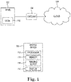
- FIG. 1 illustrates an example of a system 100 for commissioning a fire system in accordance with one or more embodiments of the present disclosure.
- the fire system 100 can be the fire control system of a facility (e.g., building), such as, for instance, a large facility having a large number of floors, such as a commercial facility, office building, hospital, and the like.
- a facility e.g., building
- the building can be a portion of a site that includes a plurality of buildings.
- the system 100 includes a panel 102, a gateway device (sometimes referred to herein simply as "gateway") 104, a mobile device 106, and a cloud 108.
- the panel 102 can be any different type of physical control panel, such as a control box, installed in the building.
- the panel 102 can have a code 110 thereon.
- the code 110 can be a bar code.
- the code 110 can be a QR code.
- the code 110 may be affixed to a surface of the panel 102.
- the code 110 can be a sticker adhered to the panel 102.
- the mobile device 106 can be a mobile computing device.
- the mobile device 106 can be a phone, tablet, laptop, etc.
- the mobile device 106 can include a processor 112 and a memory 114.
- Memory 114 can be any type of storage medium that can be accessed by processor 112 to perform various examples of the present disclosure.
- memory 114 can be a non-transitory machine-readable medium having computer readable instructions (e.g., computer program instructions) stored thereon that are executable by processor 112 to perform various examples of the present disclosure. That is, processor 112 can execute the executable instructions stored in memory 114 to perform various examples in accordance with the present disclosure.
- Memory 114 can be volatile or nonvolatile memory. Memory 652 can also be removable (e.g., portable) memory, or non-removable (e.g., internal) memory.
- memory 114 can be random access memory (RAM) (e.g., dynamic random access memory (DRAM), resistive random access memory (RRAM), and/or phase change random access memory (PCRAM)), read-only memory (ROM) (e.g., electrically erasable programmable read-only memory (EEPROM) and/or compact-disk read-only memory (CD-ROM)), flash memory, a laser disk, a digital versatile disk (DVD) or other optical disk storage, and/or a magnetic medium such as magnetic cassettes, tapes, or disks, among other types of memory.
- RAM random access memory
- DRAM dynamic random access memory
- RRAM resistive random access memory
- PCRAM phase change random access memory
- ROM read-only memory
- EEPROM electrically erasable programmable read-only memory
- memory 114 is illustrated as being located in mobile device 106, embodiments of the present disclosure are not so limited.
- memory 114 can also be located internal to another computing resource (e.g., enabling computer readable instructions to be downloaded over the Internet or another wired or wireless connection).
- the mobile device 106 can include a user interface 118.
- a user can interact with the mobile device 106 via the user interface 118.
- the user interface 118 can provide (e.g., display) information to and/or receive information from (e.g., input by) the user of the computing device.
- user interface 118 can be a graphical user interface (GUI) that can include a display (e.g., a screen) that can provide information to, and/or receive information from, the user of the mobile device 106.
- the display can be, for instance, a touch-screen (e.g., the GUI can include touch-screen capabilities).
- the user interface 118 can include a keyboard and/or mouse that the user can use to input information into the mobile device 106, and/or a speaker that can play audio to, and/or receive audio (e.g., voice input) from, the user.
- Embodiments of the present disclosure are not limited to a particular type(s) of user interface.
- the mobile device 106 can include an imaging device 116.
- the imaging device 116 can be a camera.
- the imaging device 116 can capture an image (e.g., an image of the code 110, previously discussed).
- the system 100 can include a plurality of devices located throughout a building (e.g., on different floors of the building) that can be used to detect and/or manage a fire occurring in the building, and/or to prevent a fire from occurring in the building.
- devices may include sensors (e.g., smoke detectors) that can sense a fire occurring in the facility, alarms that can provide a notification of the fire to the occupants of the facility, fans and/or dampers that can perform smoke control operations (e.g., pressurizing, purging, exhausting, etc.) during the fire, and/or sprinklers that can provide water to extinguish the fire, among other components.
- sensors e.g., smoke detectors
- alarms that can provide a notification of the fire to the occupants of the facility
- fans and/or dampers that can perform smoke control operations (e.g., pressurizing, purging, exhausting, etc.) during the fire
- sprinklers that can provide water to extinguish the fire, among other components
- the panel 102 can be used by a user to monitor and/or control devices of the system 100. For instance, a user can use the panel 102 to directly control the operation of (e.g., actions performed by) devices of the fire system. Further, the panel 102 can receive (e.g., collect) data, such as, for instance, real-time operational data, associated with the devices of the fire system. Such data can include, for instance, current operational statuses, operational states, and/or properties of the devices.
- the cloud 108 can refer to a network and/or a distributed computing environment (e.g., a cloud computing environment), a wide area network (WAN) such as the Internet, a local area network (LAN), a personal area network (PAN), a campus area network (CAN), or metropolitan area network (MAN), among other types of network relationships.
- cloud 108 can include a number of servers that receive information from, and transmit information to, gateway 108, panel 102, and/or mobile device 106 via a wired or wireless network.
- a "network” can provide a communication system that directly or indirectly links two or more computers and/or peripheral devices and allows users to access resources on other computing devices and exchange messages with other users.
- a network can allow users to share resources on their own systems with other network users and to access information on centrally located systems or on systems that are located at remote locations.
- a network can tie a number of computing devices together to form a distributed control network (e.g., cloud).
- a network may provide connections to the Internet and/or to the networks of other entities (e.g., organizations, institutions, etc.). Users may interact with network-enabled software applications to make a network request, such as to get a file or print on a network printer. Applications may also communicate with network management software, which can interact with network hardware to transmit information between devices on the network.
- entities e.g., organizations, institutions, etc.
- network management software can interact with network hardware to transmit information between devices on the network.
- the term "cloud”, or distributed control network, can be used to refer to a server and/or computing device working in conjunction with other computing resources (hardware, software, logic, memory, processor, etc.) that can be used as a service over a communications network (in a wired and/or wireless manner over the internet).
- the server, computing device, and other computing resources can all be referred to as being part of the "cloud.”
- a user can visit the building and can connect the gateway 104 to the panel 102 allowing communication between the gateway 104 and the panel 102.
- the user may be instructed to connect the gateway to the panel (e.g., via the mobile device).
- the connection may be provided using a suitable wired connection, for instance.
- the user can capture an image of (e.g., "scan") the code 110 using the imaging device 116 of the mobile device.
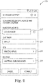
- Figure 2 illustrates an interface 220 associated with commissioning a fire system in accordance with one or more embodiments of the present disclosure.
- an indicator 222 corresponding to the panel 102 can be determined and/or displayed via the interface 220.
- the indicator 222 can be input via the interface 222 (e.g., by a user).
- the indicator 222 can be a numeric indicator, though embodiments of the present disclosure are not so limited.
- the indicator 222 may be unique to the panel 102.
- the interface 220 can include additional portions, each configured to receive a respective descriptor corresponding to the panel 102.
- a first portion 224 can be configured to receive a customer identification associated with the panel 102.
- the customer identification can be an enterprise (e.g., business) name, for instance.
- a second portion 226 can be configured to receive a site identification associated with the panel 102.
- the site identification can be a name associated with the fire control system and may include a plurality of buildings, for instance.
- a third portion 228 can be configured to receive a building identification associated with the panel 102.
- the building identification can include a name of the building in which the panel 102 is installed.
- one or more of the first portion 224, the second portion 226, and the third portion 228 can include a selectable menu and/or list.
- the customer identification, the site identification, and/or the building identification can be selected from a drop-down menu.
- a user can input (e.g., type) the customer identification, the site identification, and/or the building identification using an interface, such as the interface 118, previously discussed in connection with Figure 1 .
- the gateway Upon receiving the descriptors and/or the selection of a display element (e.g., "connect") the gateway can be configured and/or commissioned (e.g., associated with the panel and its devices).
- a panel list can be displayed that includes a plurality of panels associated with the configured gateway device. Selection of one of the panels may cause display of information corresponding to the selected panel and/or fire system devices associated with the selected panel.
- the panel list can include a respective numerical identifier for each panel and a respective location of each panel, in some embodiments.
- Figure 3 illustrates another interface 330 associated with commissioning a fire system in accordance with one or more embodiments of the present disclosure.
- the interface 330 may be herein referred to as a "test status" 330.
- subsequent scanning of the code 110 may cause the test status 330 to be displayed (e.g., via the mobile device 106, previously discussed in connection with Figure 1 ).
- a subsequent scan of the code 110 can cause the test status 330 to be displayed.
- additional user input via the mobile device may cause the test status 330 to be displayed.
- a respective test status for each of a plurality of fire system devices associated with the panel can be displayed.
- a proportion (e.g., percentage) of the plurality of devices associated with the panel for which a particular test has been performed can be displayed.
- a time associated with a most recent test performed on a device of the fire system can be displayed.
- a quantity of open corrective actions corresponding to a plurality of devices of the fire system can be displayed.
- a most recent date of inspection of the site and/or the building can be displayed.
- a quantity of devices of the fire system for which testing is overdue can be displayed.
Landscapes
- Engineering & Computer Science (AREA)
- Physics & Mathematics (AREA)
- General Physics & Mathematics (AREA)
- Business, Economics & Management (AREA)
- Emergency Management (AREA)
- Health & Medical Sciences (AREA)
- Public Health (AREA)
- General Engineering & Computer Science (AREA)
- Automation & Control Theory (AREA)
- Computer Security & Cryptography (AREA)
- Alarm Systems (AREA)
- Fire Alarms (AREA)
Abstract
Description
- The present disclosure relates generally to a commissioning a fire system.
- Large facilities (e.g., buildings), such as commercial facilities, office buildings, hospitals, and the like, may have fire control systems that can be used to prevent a fire from occurring in a facility, and/or to detect and/or manage a fire occurring in the facility. A fire control system may include a number of components located throughout the facility (e.g., on different floors of the facility). For example, a fire control system may include sensors (e.g., smoke detectors) that can sense a fire occurring in the facility, alarms that can provide a notification of the fire to the occupants of the facility, fans and/or dampers that can perform smoke control operations (e.g., pressurizing, purging, exhausting, etc.) during the fire, and/or sprinklers that can provide water to extinguish the fire, among other components. A fire control system may also include a physical fire control panel (e.g., box) installed in the facility that can be used by a user to directly control the operation of the components of the fire control system.
- A gateway device may be used by a user (e.g., maintenance technician or operator) to perform inspections, maintenance, and/or upgrades, among other operations, on a fire control system (e.g., on the components of the fire control system) of a facility. Commissioning a fire control system can include connecting a fire control panel to a network (e.g., cloud network) via a gateway.
- Previous approaches to commissioning a fire control system may include multiple users performing multiple operations at different times using different tools. The disconnect between different users and their operations can lead to delays. In an example commissioning process, an engineered systems distributor (ESD) may acquire a gateway device and wait for a technician to physically set it up. At some point after setup, the ESD may associate the panel with the customer and/or the site using a desktop tool. Previous approaches may suffer from a lack of tracking when one task is completed and the next should proceed, especially when multiple users alternate tasks.
-
-
Figure 1 illustrates an example of a system for commissioning a fire system in accordance with one or more embodiments of the present disclosure. -
Figure 2 illustrates an interface associated with commissioning a fire system in accordance with one or more embodiments of the present disclosure. -
Figure 3 illustrates another interface associated with commissioning a fire system in accordance with one or more embodiments of the present disclosure. - Commissioning a fire system is described herein. For example, embodiments include a non-transitory machine-readable medium having instructions stored thereon which, when executed by a processor, cause the processor to receive an indicator of a particular fire control panel of a fire system installed in a building, and provide an interface via a display for configuring a gateway device associated with the fire control panel responsive to receiving the indicator, the interface including a plurality of portions, wherein each portion is configured to receive a respective descriptor corresponding to the fire control panel.
- Previous approaches to commissioning a fire control system may include multiple users performing multiple operations at different times using different tools. The disconnect between different users and their operations can lead to delays. In contrast, embodiments herein can provide a seamless end-to-end workflow that allows a user (e.g., an installer, technician, etc.) to physically connect a gateway to a panel and link the panel with descriptors, such as a customer, a site, and/or a building, among other descriptors. As a result, the user can complete the commissioning in a logical order and the steps involved can be taken in one setting. The simplicity of use and intuitiveness of embodiments herein can increase the efficiency and productivity of the user. Additionally, once commissioned, a panel can be easily accessed to determine test statuses of devices of the fire system (e.g., sensors, actuators, alarms, etc.).
- In some embodiments, for example, a barcode or Quick Response (QR) code can be placed (e.g., attached, affixed, etc.) to a panel. The code can identify the panel or a gateway connected to it (e.g., via a unique identifier). The panel can be in communication with a remote network (e.g., a cloud). In some embodiments, the panel can communicate directly with the remote network. In some embodiments, the panel can communicate with the remote network via the gateway. A gateway in accordance with the present disclosure is capable of communicating with external cloud services via a wired and/or wireless connection. Using a mobile device, the code can be scanned and its identifier can be associated with a customer, a site, a building, and/or with the panel itself. Thereafter, scanning the code can allow the display of information regarding the fire system, the site, test statuses of device(s) and other information.
- In the following detailed description, reference is made to the accompanying drawings that form a part hereof. The drawings show by way of illustration how one or more embodiments of the disclosure may be practiced.
- These embodiments are described in sufficient detail to enable those of ordinary skill in the art to practice one or more embodiments of this disclosure. It is to be understood that other embodiments may be utilized and that mechanical, electrical, and/or process changes may be made without departing from the scope of the present disclosure.
- As will be appreciated, elements shown in the various embodiments herein can be added, exchanged, combined, and/or eliminated so as to provide a number of additional embodiments of the present disclosure. The proportion and the relative scale of the elements provided in the figures are intended to illustrate the embodiments of the present disclosure, and should not be taken in a limiting sense.
- The figures herein follow a numbering convention in which the first digit or digits correspond to the drawing figure number and the remaining digits identify an element or component in the drawing. Similar elements or components between different figures may be identified by the use of similar digits. For example, 101 may reference element "01" in
Figure 1 , and a similar element may be referenced as 201 inFigure 2 . - As used herein, "a", "an", or "a number of" something can refer to one or more such things, while "a plurality of" something can refer to more than one such things. For example, "a number of components" can refer to one or more components, while "a plurality of components" can refer to more than one component. Additionally, the designator "N" as used herein, particularly with respect to reference numerals in the drawings, indicates that a number of the particular feature so designated can be included with a number of embodiments of the present disclosure. This number may be the same or different between designations.
-
Figure 1 illustrates an example of a system 100 for commissioning a fire system in accordance with one or more embodiments of the present disclosure. The fire system 100 can be the fire control system of a facility (e.g., building), such as, for instance, a large facility having a large number of floors, such as a commercial facility, office building, hospital, and the like. However, embodiments of the present disclosure are not limited to a particular type of facility. The building can be a portion of a site that includes a plurality of buildings. - As shown in
Figure 1 , the system 100 includes apanel 102, a gateway device (sometimes referred to herein simply as "gateway") 104, amobile device 106, and acloud 108. Thepanel 102 can be any different type of physical control panel, such as a control box, installed in the building. - As shown, and as previously discussed, the
panel 102 can have acode 110 thereon. In some embodiments, thecode 110 can be a bar code. In some embodiments thecode 110 can be a QR code. In some embodiments, thecode 110 may be affixed to a surface of thepanel 102. For example, thecode 110 can be a sticker adhered to thepanel 102. - The
mobile device 106 can be a mobile computing device. Themobile device 106 can be a phone, tablet, laptop, etc. Themobile device 106 can include aprocessor 112 and amemory 114.Memory 114 can be any type of storage medium that can be accessed byprocessor 112 to perform various examples of the present disclosure. For example,memory 114 can be a non-transitory machine-readable medium having computer readable instructions (e.g., computer program instructions) stored thereon that are executable byprocessor 112 to perform various examples of the present disclosure. That is,processor 112 can execute the executable instructions stored inmemory 114 to perform various examples in accordance with the present disclosure. -
Memory 114 can be volatile or nonvolatile memory. Memory 652 can also be removable (e.g., portable) memory, or non-removable (e.g., internal) memory. For example,memory 114 can be random access memory (RAM) (e.g., dynamic random access memory (DRAM), resistive random access memory (RRAM), and/or phase change random access memory (PCRAM)), read-only memory (ROM) (e.g., electrically erasable programmable read-only memory (EEPROM) and/or compact-disk read-only memory (CD-ROM)), flash memory, a laser disk, a digital versatile disk (DVD) or other optical disk storage, and/or a magnetic medium such as magnetic cassettes, tapes, or disks, among other types of memory. - Further, although
memory 114 is illustrated as being located inmobile device 106, embodiments of the present disclosure are not so limited. For example,memory 114 can also be located internal to another computing resource (e.g., enabling computer readable instructions to be downloaded over the Internet or another wired or wireless connection). - The
mobile device 106 can include auser interface 118. A user can interact with themobile device 106 via theuser interface 118. For example, theuser interface 118 can provide (e.g., display) information to and/or receive information from (e.g., input by) the user of the computing device. - In some embodiments,
user interface 118 can be a graphical user interface (GUI) that can include a display (e.g., a screen) that can provide information to, and/or receive information from, the user of themobile device 106. The display can be, for instance, a touch-screen (e.g., the GUI can include touch-screen capabilities). As an additional example, theuser interface 118 can include a keyboard and/or mouse that the user can use to input information into themobile device 106, and/or a speaker that can play audio to, and/or receive audio (e.g., voice input) from, the user. Embodiments of the present disclosure, however, are not limited to a particular type(s) of user interface. - The
mobile device 106 can include animaging device 116. In some embodiments theimaging device 116 can be a camera. Theimaging device 116 can capture an image (e.g., an image of thecode 110, previously discussed). - Though not illustrated in
Figure 1 , the system 100 can include a plurality of devices located throughout a building (e.g., on different floors of the building) that can be used to detect and/or manage a fire occurring in the building, and/or to prevent a fire from occurring in the building. For example, such devices may include sensors (e.g., smoke detectors) that can sense a fire occurring in the facility, alarms that can provide a notification of the fire to the occupants of the facility, fans and/or dampers that can perform smoke control operations (e.g., pressurizing, purging, exhausting, etc.) during the fire, and/or sprinklers that can provide water to extinguish the fire, among other components. - The
panel 102 can be used by a user to monitor and/or control devices of the system 100. For instance, a user can use thepanel 102 to directly control the operation of (e.g., actions performed by) devices of the fire system. Further, thepanel 102 can receive (e.g., collect) data, such as, for instance, real-time operational data, associated with the devices of the fire system. Such data can include, for instance, current operational statuses, operational states, and/or properties of the devices. - The
cloud 108 can refer to a network and/or a distributed computing environment (e.g., a cloud computing environment), a wide area network (WAN) such as the Internet, a local area network (LAN), a personal area network (PAN), a campus area network (CAN), or metropolitan area network (MAN), among other types of network relationships. For instance,cloud 108 can include a number of servers that receive information from, and transmit information to,gateway 108,panel 102, and/ormobile device 106 via a wired or wireless network. - As used herein, a "network" can provide a communication system that directly or indirectly links two or more computers and/or peripheral devices and allows users to access resources on other computing devices and exchange messages with other users. A network can allow users to share resources on their own systems with other network users and to access information on centrally located systems or on systems that are located at remote locations. For example, a network can tie a number of computing devices together to form a distributed control network (e.g., cloud).
- A network may provide connections to the Internet and/or to the networks of other entities (e.g., organizations, institutions, etc.). Users may interact with network-enabled software applications to make a network request, such as to get a file or print on a network printer. Applications may also communicate with network management software, which can interact with network hardware to transmit information between devices on the network.
- As used herein, the term "cloud", or distributed control network, can be used to refer to a server and/or computing device working in conjunction with other computing resources (hardware, software, logic, memory, processor, etc.) that can be used as a service over a communications network (in a wired and/or wireless manner over the internet). The server, computing device, and other computing resources can all be referred to as being part of the "cloud."
- A user can visit the building and can connect the
gateway 104 to thepanel 102 allowing communication between thegateway 104 and thepanel 102. In some embodiments, the user may be instructed to connect the gateway to the panel (e.g., via the mobile device). The connection may be provided using a suitable wired connection, for instance. The user can capture an image of (e.g., "scan") thecode 110 using theimaging device 116 of the mobile device. -
Figure 2 illustrates aninterface 220 associated with commissioning a fire system in accordance with one or more embodiments of the present disclosure. After scanning thecode 110, anindicator 222 corresponding to thepanel 102 can be determined and/or displayed via theinterface 220. In some embodiments, theindicator 222 can be input via the interface 222 (e.g., by a user). Theindicator 222 can be a numeric indicator, though embodiments of the present disclosure are not so limited. Theindicator 222 may be unique to thepanel 102. - The
interface 220 can include additional portions, each configured to receive a respective descriptor corresponding to thepanel 102. For instance, afirst portion 224 can be configured to receive a customer identification associated with thepanel 102. The customer identification can be an enterprise (e.g., business) name, for instance. - A
second portion 226 can be configured to receive a site identification associated with thepanel 102. The site identification can be a name associated with the fire control system and may include a plurality of buildings, for instance. Athird portion 228 can be configured to receive a building identification associated with thepanel 102. The building identification can include a name of the building in which thepanel 102 is installed. In some embodiments, one or more of thefirst portion 224, thesecond portion 226, and thethird portion 228 can include a selectable menu and/or list. For example, one or more of the customer identification, the site identification, and/or the building identification can be selected from a drop-down menu. In some embodiments, a user can input (e.g., type) the customer identification, the site identification, and/or the building identification using an interface, such as theinterface 118, previously discussed in connection withFigure 1 . - Upon receiving the descriptors and/or the selection of a display element (e.g., "connect") the gateway can be configured and/or commissioned (e.g., associated with the panel and its devices). In some embodiments, a panel list can be displayed that includes a plurality of panels associated with the configured gateway device. Selection of one of the panels may cause display of information corresponding to the selected panel and/or fire system devices associated with the selected panel. The panel list can include a respective numerical identifier for each panel and a respective location of each panel, in some embodiments.
-
Figure 3 illustrates anotherinterface 330 associated with commissioning a fire system in accordance with one or more embodiments of the present disclosure. Theinterface 330 may be herein referred to as a "test status" 330. In accordance with embodiments of the present disclosure, once the gateway device is configured, subsequent scanning of thecode 110 may cause thetest status 330 to be displayed (e.g., via themobile device 106, previously discussed in connection withFigure 1 ). - In some embodiments, a subsequent scan of the
code 110 can cause thetest status 330 to be displayed. In some embodiments, additional user input via the mobile device may cause thetest status 330 to be displayed. In some embodiments, a respective test status for each of a plurality of fire system devices associated with the panel can be displayed. In some embodiments, a proportion (e.g., percentage) of the plurality of devices associated with the panel for which a particular test has been performed can be displayed. In some embodiments, a time associated with a most recent test performed on a device of the fire system can be displayed. In some embodiments, a quantity of open corrective actions corresponding to a plurality of devices of the fire system can be displayed. In some embodiments, a most recent date of inspection of the site and/or the building can be displayed. In some embodiments, a quantity of devices of the fire system for which testing is overdue can be displayed. - Although specific embodiments have been illustrated and described herein, those of ordinary skill in the art will appreciate that any arrangement calculated to achieve the same techniques can be substituted for the specific embodiments shown. This disclosure is intended to cover any and all adaptations or variations of various embodiments of the disclosure.
- It is to be understood that the above description has been made in an illustrative fashion, and not a restrictive one. Combination of the above embodiments, and other embodiments not specifically described herein will be apparent to those of skill in the art upon reviewing the above description.
- The scope of the various embodiments of the disclosure includes any other applications in which the above structures and methods are used. Therefore, the scope of various embodiments of the disclosure should be determined with reference to the appended claims, along with the full range of equivalents to which such claims are entitled.
- In the foregoing Detailed Description, various features are grouped together in example embodiments illustrated in the figures for the purpose of streamlining the disclosure. This method of disclosure is not to be interpreted as reflecting an intention that the embodiments of the disclosure require more features than are expressly recited in each claim.
- Rather, as the following claims reflect, inventive subject matter lies in less than all features of a single disclosed embodiment. Thus, the following claims are hereby incorporated into the Detailed Description, with each claim standing on its own as a separate embodiment.
Claims (15)
- A non-transitory machine-readable medium (114) having instructions stored thereon which, when executed by a processor (112), cause the processor (112) to:receive an indicator (222) of a particular fire control panel (102) of a fire system installed in a building; andprovide an interface (220) via a display (118) for configuring a gateway device (104) associated with the fire control panel (102) responsive to receiving the indicator (222), the interface (220) including a plurality of portions (224, 226, 228), wherein each portion (224, 226, 228) is configured to receive a respective descriptor corresponding to the fire control panel (102).
- The medium (114) of claim 1, wherein the instructions to receive the indicator (222) include instructions to receive an image of a machine-readable code (110) corresponding to the particular fire control panel (102) of the fire system installed in the building.
- The medium (114) of claim 1, wherein the instructions to provide the interface (220) include instructions to provide:a first portion (224) of the interface (220) configured to receive a customer identification associated with the fire control panel (102);a second portion (226) of the interface (220) configured to receive a site identification associated with the fire control panel (102); anda third portion (228) of the interface (220) configured to receive a building identification associated with the fire control panel (102).
- The medium (114) of claim 1, including instructions to configure the gateway device (104) based on the respective descriptors while the gateway device (104) is physically connected to the fire control panel (102).
- The medium (114) of claim 1, wherein each portion is configured to receive a respective descriptor selected from a list of descriptors.
- A method of commissioning a fire control system, comprising:receive an image of a machine-readable code (110) corresponding to a particular fire control panel (102) of a fire system installed in a building at a site;determine an identity of the particular fire control panel (102) based on the image;provide an interface (220) via a display (118) for configuring a gateway device (104) associated with the fire control panel (102) responsive to receiving the indicator (222), the interface (220) including a plurality of portions (224, 226, 228), wherein each portion (224, 226, 228) is configured to receive a respective descriptor corresponding to the fire control panel (102);receiving the respective descriptors via the interface (220);configuring the gateway device (104) based on the respective descriptors;receiving a subsequent image of the machine-readable code (110); anddisplaying a test status (330) associated with the fire control panel (102) via the display (118) responsive to determining the identity of the particular fire control panel (102) based on the subsequent image.
- The method of claim 6, wherein the method includes displaying a panel list including a plurality of fire control panels (102) associated with the gateway device (104) responsive to configuring the gateway device (104) based on the respective descriptors.
- The method of claim 7, wherein the method includes displaying, for each of the plurality of fire control panels (102) associated with the gateway device (104):a respective numerical identifier; anda respective location.
- The method of claim 6, wherein the method includes displaying the test status (330) associated with the fire control panel (102) via the display (118) responsive to receiving the identity of the particular fire control panel (102) via an interface (220) of a mobile device 106.
- The method of claim 6, wherein displaying the test status (330) includes displaying a respective test status (330) for each of a plurality of devices of the fire system associated with the fire control panel (102).
- The method of claim 10, wherein displaying the test status (330) includes displaying a proportion of the plurality of devices for which a particular test has been performed.
- The method of claim 6, wherein displaying the test status (330) includes displaying a time associated with a most recent test performed on a device of the fire system.
- The method of claim 6, wherein displaying the test status (330) includes displaying a quantity of open corrective actions corresponding to a plurality of devices of the fire system.
- The method of claim 6, wherein displaying the test status (330) includes displaying a most recent date of inspection of the site.
- The method of claim 6, wherein displaying the test status (330) includes displaying a quantity of devices of the fire system for which testing is overdue.
Applications Claiming Priority (1)
| Application Number | Priority Date | Filing Date | Title |
|---|---|---|---|
| US17/147,095 US11872429B2 (en) | 2021-01-12 | 2021-01-12 | Commissioning a fire system |
Publications (2)
| Publication Number | Publication Date |
|---|---|
| EP4033467A1 true EP4033467A1 (en) | 2022-07-27 |
| EP4033467B1 EP4033467B1 (en) | 2024-10-09 |
Family
ID=79230880
Family Applications (1)
| Application Number | Title | Priority Date | Filing Date |
|---|---|---|---|
| EP22150285.9A Active EP4033467B1 (en) | 2021-01-12 | 2022-01-05 | Instructions and method for commissioning a fire system |
Country Status (2)
| Country | Link |
|---|---|
| US (1) | US11872429B2 (en) |
| EP (1) | EP4033467B1 (en) |
Cited By (1)
| Publication number | Priority date | Publication date | Assignee | Title |
|---|---|---|---|---|
| US20240064273A1 (en) * | 2022-08-17 | 2024-02-22 | Honeywell International Inc. | System gateway analysis |
Families Citing this family (3)
| Publication number | Priority date | Publication date | Assignee | Title |
|---|---|---|---|---|
| US11511145B1 (en) * | 2019-06-19 | 2022-11-29 | Minimax Viking Research & Development Gmbh | Fast response glass bulb thermal trigger arrangements and methods thereof for large orifice suppression fire protection sprinklers |
| CN116527698A (en) * | 2022-11-29 | 2023-08-01 | 中冶南方(武汉)自动化有限公司 | System for realizing intelligent butt joint of fire control system and building equipment management system |
| US20260004652A1 (en) * | 2024-06-26 | 2026-01-01 | Kidde Fire Protection, Llc | System and method for development of fire panel system configuration through networked configuration utility instances |
Citations (3)
| Publication number | Priority date | Publication date | Assignee | Title |
|---|---|---|---|---|
| US20120154141A1 (en) * | 2010-12-17 | 2012-06-21 | Piccolo Iii Joseph | Method and system for wireless configuration, control, and status reporting of devices in a fire alarm system |
| US20170230930A1 (en) * | 2016-02-09 | 2017-08-10 | Siemens Schweiz Ag | Method And Arrangement For Commissioning A Building Automation System |
| US20200304494A1 (en) * | 2019-03-20 | 2020-09-24 | Honeywell International Inc. | Multi-level authentication for a fire control system |
Family Cites Families (10)
| Publication number | Priority date | Publication date | Assignee | Title |
|---|---|---|---|---|
| US8447070B1 (en) * | 2010-04-19 | 2013-05-21 | Amazon Technologies, Inc. | Approaches for device location and communication |
| US9575477B2 (en) * | 2012-07-31 | 2017-02-21 | International Business Machines Corporation | Sensor installation in a building management system |
| US9019069B2 (en) * | 2013-02-07 | 2015-04-28 | Sensormatic Electronics, LLC | Configuration of security devices using spatially-encoded optical machine-readable indicia |
| EP3053379A4 (en) * | 2013-09-30 | 2017-05-03 | Schneider Electric Industries SAS | Cloud-authenticated site resource management devices, apparatuses, methods and systems |
| US20160086045A1 (en) | 2014-09-23 | 2016-03-24 | Schneider Electric Buildings, Llc | Commissioning hvac device with optical communication |
| US20170099647A1 (en) * | 2015-10-05 | 2017-04-06 | Nebulae LLC | Systems and Methods for Registering Devices in a Wireless Network |
| US20180011461A1 (en) * | 2016-07-07 | 2018-01-11 | Tyco Fire & Security Gmbh | Building Asset Management System |
| US10769935B2 (en) * | 2016-09-12 | 2020-09-08 | Sensormatic Electronics, LLC | Method and apparatus for unified mobile application for installation of security products |
| US11282301B2 (en) * | 2017-12-29 | 2022-03-22 | Matthew Higgins | Method and system for systematic maintenance of mechanical and electrical equipment |
| EP3885734A1 (en) * | 2020-03-27 | 2021-09-29 | Viavi Solutions Inc. | Quick response (qr) code based test data embedding and transmission |
-
2021
- 2021-01-12 US US17/147,095 patent/US11872429B2/en active Active
-
2022
- 2022-01-05 EP EP22150285.9A patent/EP4033467B1/en active Active
Patent Citations (3)
| Publication number | Priority date | Publication date | Assignee | Title |
|---|---|---|---|---|
| US20120154141A1 (en) * | 2010-12-17 | 2012-06-21 | Piccolo Iii Joseph | Method and system for wireless configuration, control, and status reporting of devices in a fire alarm system |
| US20170230930A1 (en) * | 2016-02-09 | 2017-08-10 | Siemens Schweiz Ag | Method And Arrangement For Commissioning A Building Automation System |
| US20200304494A1 (en) * | 2019-03-20 | 2020-09-24 | Honeywell International Inc. | Multi-level authentication for a fire control system |
Cited By (2)
| Publication number | Priority date | Publication date | Assignee | Title |
|---|---|---|---|---|
| US20240064273A1 (en) * | 2022-08-17 | 2024-02-22 | Honeywell International Inc. | System gateway analysis |
| US12183077B2 (en) * | 2022-08-17 | 2024-12-31 | Honeywell International Inc. | System gateway analysis |
Also Published As
| Publication number | Publication date |
|---|---|
| US11872429B2 (en) | 2024-01-16 |
| EP4033467B1 (en) | 2024-10-09 |
| US20220219032A1 (en) | 2022-07-14 |
Similar Documents
| Publication | Publication Date | Title |
|---|---|---|
| EP4033467B1 (en) | Instructions and method for commissioning a fire system | |
| US11475758B2 (en) | Monitoring control panels of a fire control system | |
| US20250013992A1 (en) | Method and system for aggregating diagnostic analyzer related information | |
| US20230216765A1 (en) | Edge system health monitoring and auditing | |
| US20180285831A1 (en) | Automatic work order generation for a building management system | |
| US11055619B2 (en) | Systems and methods for energy expert collaboration features | |
| CN106130749B (en) | Method, system, and computer-readable medium for network deployment of infrastructure | |
| US11651415B2 (en) | On-demand service providing system and on-demand service providing method | |
| US20200365004A1 (en) | Translating building automation events into mobile notifications | |
| KR20150110985A (en) | a facility integrated management system and method of facility integrated management | |
| GB2507041A (en) | Property management system | |
| US11847902B2 (en) | Gateway device for a fire control system | |
| US20190137958A1 (en) | Data collection for assistance in an industrial automation environment | |
| US20240223696A1 (en) | AUTOMATE-AUTOMATED INTERFACE BETWEEN CALL CENTER AGENTS AND NETWORK ORCHESTRATION SYSTEMS VIA APPLICATION PROGRAMMING INTERFACES (APIs) | |
| JP7788256B2 (en) | Equipment Management System | |
| US10972314B2 (en) | Gateway device for a fire control system | |
| JP2020068408A (en) | Impact range notification device, impact range notification system, impact range notification method, and program | |
| JP2025071665A (en) | Information processing device, information processing method, and program | |
| KR20100012936A (en) | Building management system with mss system and control method building management system with mss system |
Legal Events
| Date | Code | Title | Description |
|---|---|---|---|
| PUAI | Public reference made under article 153(3) epc to a published international application that has entered the european phase |
Free format text: ORIGINAL CODE: 0009012 |
|
| STAA | Information on the status of an ep patent application or granted ep patent |
Free format text: STATUS: REQUEST FOR EXAMINATION WAS MADE |
|
| 17P | Request for examination filed |
Effective date: 20220105 |
|
| AK | Designated contracting states |
Kind code of ref document: A1 Designated state(s): AL AT BE BG CH CY CZ DE DK EE ES FI FR GB GR HR HU IE IS IT LI LT LU LV MC MK MT NL NO PL PT RO RS SE SI SK SM TR |
|
| P01 | Opt-out of the competence of the unified patent court (upc) registered |
Effective date: 20230523 |
|
| GRAP | Despatch of communication of intention to grant a patent |
Free format text: ORIGINAL CODE: EPIDOSNIGR1 |
|
| STAA | Information on the status of an ep patent application or granted ep patent |
Free format text: STATUS: GRANT OF PATENT IS INTENDED |
|
| INTG | Intention to grant announced |
Effective date: 20240605 |
|
| GRAS | Grant fee paid |
Free format text: ORIGINAL CODE: EPIDOSNIGR3 |
|
| GRAA | (expected) grant |
Free format text: ORIGINAL CODE: 0009210 |
|
| STAA | Information on the status of an ep patent application or granted ep patent |
Free format text: STATUS: THE PATENT HAS BEEN GRANTED |
|
| AK | Designated contracting states |
Kind code of ref document: B1 Designated state(s): AL AT BE BG CH CY CZ DE DK EE ES FI FR GB GR HR HU IE IS IT LI LT LU LV MC MK MT NL NO PL PT RO RS SE SI SK SM TR |
|
| REG | Reference to a national code |
Ref country code: CH Ref legal event code: EP |
|
| REG | Reference to a national code |
Ref country code: DE Ref legal event code: R096 Ref document number: 602022006549 Country of ref document: DE |
|
| REG | Reference to a national code |
Ref country code: IE Ref legal event code: FG4D |
|
| REG | Reference to a national code |
Ref country code: LT Ref legal event code: MG9D |
|
| REG | Reference to a national code |
Ref country code: NL Ref legal event code: MP Effective date: 20241009 |
|
| REG | Reference to a national code |
Ref country code: AT Ref legal event code: MK05 Ref document number: 1731447 Country of ref document: AT Kind code of ref document: T Effective date: 20241009 |
|
| PG25 | Lapsed in a contracting state [announced via postgrant information from national office to epo] |
Ref country code: NL Free format text: LAPSE BECAUSE OF FAILURE TO SUBMIT A TRANSLATION OF THE DESCRIPTION OR TO PAY THE FEE WITHIN THE PRESCRIBED TIME-LIMIT Effective date: 20241009 |
|
| PG25 | Lapsed in a contracting state [announced via postgrant information from national office to epo] |
Ref country code: NL Free format text: LAPSE BECAUSE OF FAILURE TO SUBMIT A TRANSLATION OF THE DESCRIPTION OR TO PAY THE FEE WITHIN THE PRESCRIBED TIME-LIMIT Effective date: 20241009 |
|
| PG25 | Lapsed in a contracting state [announced via postgrant information from national office to epo] |
Ref country code: PT Free format text: LAPSE BECAUSE OF FAILURE TO SUBMIT A TRANSLATION OF THE DESCRIPTION OR TO PAY THE FEE WITHIN THE PRESCRIBED TIME-LIMIT Effective date: 20250210 Ref country code: IS Free format text: LAPSE BECAUSE OF FAILURE TO SUBMIT A TRANSLATION OF THE DESCRIPTION OR TO PAY THE FEE WITHIN THE PRESCRIBED TIME-LIMIT Effective date: 20250209 Ref country code: HR Free format text: LAPSE BECAUSE OF FAILURE TO SUBMIT A TRANSLATION OF THE DESCRIPTION OR TO PAY THE FEE WITHIN THE PRESCRIBED TIME-LIMIT Effective date: 20241009 |
|
| PG25 | Lapsed in a contracting state [announced via postgrant information from national office to epo] |
Ref country code: FI Free format text: LAPSE BECAUSE OF FAILURE TO SUBMIT A TRANSLATION OF THE DESCRIPTION OR TO PAY THE FEE WITHIN THE PRESCRIBED TIME-LIMIT Effective date: 20241009 |
|
| PG25 | Lapsed in a contracting state [announced via postgrant information from national office to epo] |
Ref country code: BG Free format text: LAPSE BECAUSE OF FAILURE TO SUBMIT A TRANSLATION OF THE DESCRIPTION OR TO PAY THE FEE WITHIN THE PRESCRIBED TIME-LIMIT Effective date: 20241009 |
|
| PG25 | Lapsed in a contracting state [announced via postgrant information from national office to epo] |
Ref country code: ES Free format text: LAPSE BECAUSE OF FAILURE TO SUBMIT A TRANSLATION OF THE DESCRIPTION OR TO PAY THE FEE WITHIN THE PRESCRIBED TIME-LIMIT Effective date: 20241009 |
|
| PG25 | Lapsed in a contracting state [announced via postgrant information from national office to epo] |
Ref country code: NO Free format text: LAPSE BECAUSE OF FAILURE TO SUBMIT A TRANSLATION OF THE DESCRIPTION OR TO PAY THE FEE WITHIN THE PRESCRIBED TIME-LIMIT Effective date: 20250109 |
|
| PG25 | Lapsed in a contracting state [announced via postgrant information from national office to epo] |
Ref country code: LV Free format text: LAPSE BECAUSE OF FAILURE TO SUBMIT A TRANSLATION OF THE DESCRIPTION OR TO PAY THE FEE WITHIN THE PRESCRIBED TIME-LIMIT Effective date: 20241009 Ref country code: GR Free format text: LAPSE BECAUSE OF FAILURE TO SUBMIT A TRANSLATION OF THE DESCRIPTION OR TO PAY THE FEE WITHIN THE PRESCRIBED TIME-LIMIT Effective date: 20250110 Ref country code: AT Free format text: LAPSE BECAUSE OF FAILURE TO SUBMIT A TRANSLATION OF THE DESCRIPTION OR TO PAY THE FEE WITHIN THE PRESCRIBED TIME-LIMIT Effective date: 20241009 |
|
| PG25 | Lapsed in a contracting state [announced via postgrant information from national office to epo] |
Ref country code: PL Free format text: LAPSE BECAUSE OF FAILURE TO SUBMIT A TRANSLATION OF THE DESCRIPTION OR TO PAY THE FEE WITHIN THE PRESCRIBED TIME-LIMIT Effective date: 20241009 |
|
| PG25 | Lapsed in a contracting state [announced via postgrant information from national office to epo] |
Ref country code: RS Free format text: LAPSE BECAUSE OF FAILURE TO SUBMIT A TRANSLATION OF THE DESCRIPTION OR TO PAY THE FEE WITHIN THE PRESCRIBED TIME-LIMIT Effective date: 20250109 |
|
| PG25 | Lapsed in a contracting state [announced via postgrant information from national office to epo] |
Ref country code: SM Free format text: LAPSE BECAUSE OF FAILURE TO SUBMIT A TRANSLATION OF THE DESCRIPTION OR TO PAY THE FEE WITHIN THE PRESCRIBED TIME-LIMIT Effective date: 20241009 |
|
| PG25 | Lapsed in a contracting state [announced via postgrant information from national office to epo] |
Ref country code: DK Free format text: LAPSE BECAUSE OF FAILURE TO SUBMIT A TRANSLATION OF THE DESCRIPTION OR TO PAY THE FEE WITHIN THE PRESCRIBED TIME-LIMIT Effective date: 20241009 |
|
| REG | Reference to a national code |
Ref country code: DE Ref legal event code: R097 Ref document number: 602022006549 Country of ref document: DE |
|
| PG25 | Lapsed in a contracting state [announced via postgrant information from national office to epo] |
Ref country code: EE Free format text: LAPSE BECAUSE OF FAILURE TO SUBMIT A TRANSLATION OF THE DESCRIPTION OR TO PAY THE FEE WITHIN THE PRESCRIBED TIME-LIMIT Effective date: 20241009 |
|
| PG25 | Lapsed in a contracting state [announced via postgrant information from national office to epo] |
Ref country code: RO Free format text: LAPSE BECAUSE OF FAILURE TO SUBMIT A TRANSLATION OF THE DESCRIPTION OR TO PAY THE FEE WITHIN THE PRESCRIBED TIME-LIMIT Effective date: 20241009 |
|
| PG25 | Lapsed in a contracting state [announced via postgrant information from national office to epo] |
Ref country code: SK Free format text: LAPSE BECAUSE OF FAILURE TO SUBMIT A TRANSLATION OF THE DESCRIPTION OR TO PAY THE FEE WITHIN THE PRESCRIBED TIME-LIMIT Effective date: 20241009 |
|
| PG25 | Lapsed in a contracting state [announced via postgrant information from national office to epo] |
Ref country code: CZ Free format text: LAPSE BECAUSE OF FAILURE TO SUBMIT A TRANSLATION OF THE DESCRIPTION OR TO PAY THE FEE WITHIN THE PRESCRIBED TIME-LIMIT Effective date: 20241009 |
|
| PG25 | Lapsed in a contracting state [announced via postgrant information from national office to epo] |
Ref country code: IT Free format text: LAPSE BECAUSE OF FAILURE TO SUBMIT A TRANSLATION OF THE DESCRIPTION OR TO PAY THE FEE WITHIN THE PRESCRIBED TIME-LIMIT Effective date: 20241009 |
|
| PLBE | No opposition filed within time limit |
Free format text: ORIGINAL CODE: 0009261 |
|
| STAA | Information on the status of an ep patent application or granted ep patent |
Free format text: STATUS: NO OPPOSITION FILED WITHIN TIME LIMIT |
|
| REG | Reference to a national code |
Ref country code: CH Ref legal event code: PL |
|
| PG25 | Lapsed in a contracting state [announced via postgrant information from national office to epo] |
Ref country code: SE Free format text: LAPSE BECAUSE OF FAILURE TO SUBMIT A TRANSLATION OF THE DESCRIPTION OR TO PAY THE FEE WITHIN THE PRESCRIBED TIME-LIMIT Effective date: 20241009 |
|
| PG25 | Lapsed in a contracting state [announced via postgrant information from national office to epo] |
Ref country code: MC Free format text: LAPSE BECAUSE OF FAILURE TO SUBMIT A TRANSLATION OF THE DESCRIPTION OR TO PAY THE FEE WITHIN THE PRESCRIBED TIME-LIMIT Effective date: 20241009 Ref country code: LU Free format text: LAPSE BECAUSE OF NON-PAYMENT OF DUE FEES Effective date: 20250105 |
|
| 26N | No opposition filed |
Effective date: 20250710 |
|
| PG25 | Lapsed in a contracting state [announced via postgrant information from national office to epo] |
Ref country code: BE Free format text: LAPSE BECAUSE OF NON-PAYMENT OF DUE FEES Effective date: 20250131 |
|
| PG25 | Lapsed in a contracting state [announced via postgrant information from national office to epo] |
Ref country code: CH Free format text: LAPSE BECAUSE OF NON-PAYMENT OF DUE FEES Effective date: 20250131 |
|
| REG | Reference to a national code |
Ref country code: BE Ref legal event code: MM Effective date: 20250131 |
|
| PG25 | Lapsed in a contracting state [announced via postgrant information from national office to epo] |
Ref country code: IE Free format text: LAPSE BECAUSE OF NON-PAYMENT OF DUE FEES Effective date: 20250105 |
|
| PGFP | Annual fee paid to national office [announced via postgrant information from national office to epo] |
Ref country code: GB Payment date: 20260126 Year of fee payment: 5 |
|
| PGFP | Annual fee paid to national office [announced via postgrant information from national office to epo] |
Ref country code: DE Payment date: 20260127 Year of fee payment: 5 |
|
| PGFP | Annual fee paid to national office [announced via postgrant information from national office to epo] |
Ref country code: FR Payment date: 20260127 Year of fee payment: 5 |