EP4033329A1 - Multiple supply and return connections for liquid cooling loop assemblies - Google Patents
Multiple supply and return connections for liquid cooling loop assemblies Download PDFInfo
- Publication number
- EP4033329A1 EP4033329A1 EP21211004.3A EP21211004A EP4033329A1 EP 4033329 A1 EP4033329 A1 EP 4033329A1 EP 21211004 A EP21211004 A EP 21211004A EP 4033329 A1 EP4033329 A1 EP 4033329A1
- Authority
- EP
- European Patent Office
- Prior art keywords
- cooling
- rack
- manifold
- return
- connectors
- Prior art date
- Legal status (The legal status is an assumption and is not a legal conclusion. Google has not performed a legal analysis and makes no representation as to the accuracy of the status listed.)
- Granted
Links
Images









Classifications
-
- G—PHYSICS
- G06—COMPUTING OR CALCULATING; COUNTING
- G06F—ELECTRIC DIGITAL DATA PROCESSING
- G06F1/00—Details not covered by groups G06F3/00 - G06F13/00 and G06F21/00
- G06F1/16—Constructional details or arrangements
- G06F1/20—Cooling means
-
- H—ELECTRICITY
- H05—ELECTRIC TECHNIQUES NOT OTHERWISE PROVIDED FOR
- H05K—PRINTED CIRCUITS; CASINGS OR CONSTRUCTIONAL DETAILS OF ELECTRIC APPARATUS; MANUFACTURE OF ASSEMBLAGES OF ELECTRICAL COMPONENTS
- H05K7/00—Constructional details common to different types of electric apparatus
- H05K7/20—Modifications to facilitate cooling, ventilating, or heating
- H05K7/20709—Modifications to facilitate cooling, ventilating, or heating for server racks or cabinets; for data centers, e.g. 19-inch computer racks
- H05K7/20763—Liquid cooling without phase change
- H05K7/20772—Liquid cooling without phase change within server blades for removing heat from heat source
-
- H—ELECTRICITY
- H05—ELECTRIC TECHNIQUES NOT OTHERWISE PROVIDED FOR
- H05K—PRINTED CIRCUITS; CASINGS OR CONSTRUCTIONAL DETAILS OF ELECTRIC APPARATUS; MANUFACTURE OF ASSEMBLAGES OF ELECTRICAL COMPONENTS
- H05K7/00—Constructional details common to different types of electric apparatus
- H05K7/20—Modifications to facilitate cooling, ventilating, or heating
- H05K7/20709—Modifications to facilitate cooling, ventilating, or heating for server racks or cabinets; for data centers, e.g. 19-inch computer racks
- H05K7/20763—Liquid cooling without phase change
- H05K7/20781—Liquid cooling without phase change within cabinets for removing heat from server blades
-
- G—PHYSICS
- G06—COMPUTING OR CALCULATING; COUNTING
- G06F—ELECTRIC DIGITAL DATA PROCESSING
- G06F2200/00—Indexing scheme relating to G06F1/04 - G06F1/32
- G06F2200/20—Indexing scheme relating to G06F1/20
- G06F2200/201—Cooling arrangements using cooling fluid
Definitions
- This application relates to the field of electronics, and particularly thermal management and cooling of chip assemblies utilizing liquid cooling.
- Liquid cooling can be used within computing equipment and on data center racks to aid in the reduction of heat generated by microelectronic elements within the chip assemblies, as well as heat generated by components external to the assembly.
- Liquid cooling is one method in which to remove heat in the system and to maintain components, such as chip assemblies and microprocessors, within the system within operating temperature limits. Liquid cooling allows for removal of the excess heat with heat transfer fluid pumped into a cooling device and the heated return cooling liquid pumped out of the device.
- a system for thermal management of computing devices comprises a central supply line coupled to a fluid source of cooling liquid; a central return line coupled to the fluid source; a rack supply manifold coupled to the central supply line; a rack return manifold coupled to the central return line; and a loop assembly coupled to the rack supply manifold and the rack return manifold.
- the cooling loop assembly can be coupled to at least one cooling device that is electrically connected to a circuit board, the cooling loop assembly further comprising multiple inlet connectors connected to the rack supply manifold; and multiple outlet connectors connected to the rack return manifold.
- the multiple inlet connectors may provide a passageway for the cooling liquid from the central supply line into the cooling loop assembly for distribution to the at least one cooling device.
- the multiple outlet connectors may provide a passageway to the rack return manifold for the cooling liquid exiting the at least two of the cooling devices.
- each multiple inlet connector may be coupled to a board supply line that feeds fluid from the rack supply manifold into the cooling loop assembly and into the at least one cooling device.
- the cooling loop assembly can further comprise a board inlet manifold and secondary supply lines.
- the secondary supply lines may connect the board inlet manifold to the at least one cooling device.
- the cooling loop assembly can additionally or alternatively comprise board return lines coupled to each multiple outlet connector.
- the cooling liquid may return from the at least one cooling device flows through each of the board return lines and the multiple outlet connectors.
- the cooling loop assembly can comprise a board outlet manifold and secondary return lines connecting the multiple outlet connectors to the board outlet manifold.
- the at least one cooling device is two or more cooling devices, and the multiple inlet connectors are at least two inlet connectors. Additionally, in some examples, the multiple outlet connectors may be at least two outlet connectors.
- the rack supply manifold and the rack return manifold may be positioned on opposed sides of the two or more cooling devices. In other examples, the rack supply manifold and the rack return manifold are positioned on a same side of the two or more cooling devices.
- the multiple inlet connectors and the multiple outlet connectors are first multiple inlet connectors and first multiple outlet connectors.
- the cooling loop assembly may be a first cooling loop assembly and the system may further include a second cooling loop assembly coupled to the rack supply manifold and rack return manifold.
- the first cooling loop assembly may overlie the second cooling loop assembly.
- the second cooling loop assembly may be coupled to at least one other cooling device connected to another circuit board.
- the rack supply manifold may be a first rack supply manifold and the rack return manifold may be a first rack return manifold.
- the system may further comprise a second central supply line; a second central return line; a second rack supply manifold coupled to the second central supply line; and a second rack return manifold coupled to the second central return line.
- At least one of the multiple inlet connectors may be connected to the second rack supply manifold.
- At least one of the multiple outlet connectors may be connected to the second rack return manifold.
- the at least one of the multiple inlet connectors may provide a passageway for the cooling liquid from the second central supply line into the cooling loop assembly for distribution to the at least one cooling device.
- the at least one of the multiple outlet connectors provide a passageway to the second rack return manifold for the cooling liquid to exit the at least one of the cooling devices.
- the multiple inlet connectors and the multiple outlet connectors may comprise quick disconnect couplings.
- a system comprises a circuit board; a plurality of microelectronic assemblies electronically connected to the circuit board; a plurality of cooling devices; and a cooling loop assembly.
- the plurality of cooling devices may overlie a first microelectronic assembly and a second microelectronic assembly of the plurality of microelectronic assemblies and be configured to cool the first and second microelectronic assemblies.
- the cooling loop assembly may be coupled to the plurality of the cooling devices and overlie the circuit board.
- the cooling loop assembly can comprise multiple inlet connectors configured to be coupled to an assembly fluid source external to the circuit board; and multiple outlet connectors configured to be coupled to an assembly return line external to the circuit board.
- the multiple inlet connectors provide a passageway for cooling liquid from the assembly fluid source into the cooling loop assembly for distribution to the at least two of the cooling devices.
- the multiple outlet connectors may provide a passageway to the assembly return line for the cooling liquid exiting the at least two of the cooling devices.
- each of the multiple inlet connectors is attached to a board supply line overlying the circuit board and that feeds fluid into the cooling loop assembly and into the at least two of the cooling devices.
- an outlet return line may overlie the circuit board and be connected to each of the multiple outlet connectors. The cooling liquid returning from each of the at least two of the cooling devices may flow through each of the outlet return lines and the multiple outlet connectors.
- the inlet connectors and outlet connectors are quick disconnect couplings and the outlet connectors are quick disconnect couplings.
- a system for thermal management of computing devices comprises a rack supply manifold connected to a supply line; a rack return manifold connected to a central return line; and a first cooling loop assembly and a second cooling loop assembly coupled to the rack supply manifold and the rack return manifold.
- the first cooling loop assembly may be coupled to at least one cooling device that is electrically connected to a circuit board.
- the first cooling loop assembly comprises at least one inlet connector coupled to the rack supply manifold.
- the at least one inlet connector provides a passageway for cooling liquid from the rack supply manifold into the first cooling loop assembly for distribution to the at least one cooling device.
- At least one outlet connector may be coupled to the rack return manifold.
- the at least one outlet connector may provide a passageway for cooling liquid exiting the at least one cooling device to the rack return manifold.
- At least one of the at least one inlet connector and the at least one outlet connector is a plurality of inlet connectors or outlet connectors.
- the second cooling loop assembly may be coupled to at least one other cooling device connected to the circuit board.
- the second cooling loop assembly may comprise at least one inlet connector of the second cooling loop assembly coupled to the rack supply manifold; and at least one outlet connector of the second cooling loop assembly coupled to the rack return manifold.
- the at least one inlet connector may provide a passageway for the cooling liquid from the rack supply manifold into the second cooling loop assembly for distribution to the at least one other cooling device.
- the at least one outlet connector may provide a passageway to the rack return manifold for the cooling liquid exiting the at least one other cooling device.
- At least one of the at least one inlet connector and the at least one outlet connector of the second cooling loop assembly is a plurality of inlet connectors or outlet connectors.
- the at least one connector of the first cooling loop assembly and the at least one connector of the second cooling loop assembly comprise a plurality of inlet connectors.
- Liquid cooling systems and cold plates are used to dissipate heat within chip assemblies, computing systems, and data server rack systems.
- Liquid cooled processors require higher coolant flow rate to maintain the computing performance and system reliability.
- liquid flow rate must also increase to keep up with increased heat created by the chips. This can lead to significant rise in pressure drop through connections for cooling loop assemblies. Further, pumping power consumed by pressure drop in connectors does not contribute to cooling.
- the improved cooling system can include a single cooling loop with multiple quick disconnects provided at the supply interface and multiple disconnects provided at the return interface. This allows for the lowest pressure drop through the connections and the cooling loop, versatility, and a design that is easily scalable for increased number of supply and returns. Additionally, it can prevent mechanical conflict in the machine due to prior art single supply and return hoses.
- FIGURE 1 is an example system 100 that includes a cooling loop assembly 110 with multiple inlets and multiple outlets for thermal management and liquid cooling of microelectronic assemblies, including chips, such as semiconductor chips, or other devices (not shown) on a circuit board 120 of a computing device 122.
- the circuit board 120 may include a motherboard, main board or the like.
- the cooling loop assembly 110 may be the only loop implemented on the circuit board 120 for cooling all components connected to the cooling loop assembly 110 on the circuit board 120, but the cooling loop assembly 110 can be implemented with other loops on the circuit board 120, as well.
- cooling loop assembly 110 is fluidly connected to each of the cooling devices 130a,130b, 130c,130d on the circuit board 120.
- Each cooling device 130a,130b, 130c, 130d may include a respective inlet 132a, 132b, 132c, 132d and a corresponding outlet 134a, 134b, 134c, 134d.
- Cooling loop assembly 110 and corresponding computing device 122 may be one of a plurality of cooling loops and computing devices in a data center server rack ( see FIGURE 2 ), but in other examples the cooling loop may be utilized for a standalone individual computing device and cooling loop.
- Cooling loop assembly 110 may include at least two inlet connectors: a first inlet connector 140a and a second inlet connector 140b, but a single inlet connection or more than two inlet connectors may also be utilized. Cooling loop assembly 110 further includes at least two outlet connectors: a first outlet connector 142a and a second outlet connector 142b, but a single outlet connector or more than two outlet connectors may also be utilized.
- first and second inlet connectors 140a, 140b may be coupled or connected to a single liquid cooling inlet source or manifold (not shown in this view) of a larger cooling system (see FIGURE 3 ), and first and second outlet connectors may be coupled or connected to a single liquid cooling outlet or manifold (not shown in this view).
- the first and second inlet connectors 140a, 140b, as well as the first and second outlet connectors 142a, 142b may be quick disconnect couplings or fittings that are designed to provide fast and easy connection and disconnection of lines to the respective inlet source and outlet source.
- quick disconnect fittings can include snap type (spring loaded ball latching), non-latching, double shut-off, and dry break quick disconnect fittings. Utilizing quick disconnect fittings can provide a higher pressure drop than simpler or other types of mechanical fittings. Further, quick disconnect fittings do not require the use of tools to assemble and disassemble. In other examples, different types of connectors may be utilized, such as quick connectors.
- a first board supply line 144a connects the first inlet connector 140a to the board inlet manifold 150 and a second board supply line 144b connects the second inlet connector 140b to the board inlet manifold 150.
- Cooling liquid is distributed across the circuit board 120 along a length of the board inlet manifold 150. This enables cooling liquid to reach and be distributed to each of the cooling devices 130a,130b, 130c,130d.
- the board inlet manifold 150 is positioned adjacent at least one of the edges of each of the cooling devices 130a,130b,130c,130d. But, in other examples, the board inlet manifold 150 can be positioned anywhere on the circuit board 120 and may be any shape or size.
- Secondary supply lines 146a,146b,146c,146d may extend from the board inlet manifold 150 to the inlets 132a, 132b, 132c, 132b of each respective cooling device 130a,130b,130c,130d.
- a first return line 148a joins the first outlet connector 142a to the board outlet manifold 152 and a second return line 148b joins the second outlet connector 142b to the board outlet manifold 152.
- the board outlet manifold 152 can run parallel to the board inlet manifold 150 and in this example, extends along a length L of the circuit board and adjacent at least one edge of each of the cooling devices 130a,130b, 130c, 130d.
- Secondary return lines 154a,154b,154c,154d extend between the board outlet manifold 152 and each of the outlets 134a, 134b, 134c, 134d of the respective cooling devices 130a, 130b, 130c, 130d.
- the supply and return lines, as well as any secondary supply and return lines and manifolds may be hoses, pipes, or other structures that enable fluid to move from a liquid source through the inlet connections, through the cooling loop assembly and cooling devices, and back out through the return lines to an outlet.
- the supply and return lines may be flexible hoses or pipes to allow for easier user handling.
- the supply and return lines may be more rigid to better allow for automation of the connection and disconnection of the return and supply lines.
- the system may incorporate both flexible and rigid lines.
- the cooling devices 130a, 130b, 130c, 130d may be conventional liquid cooling devices, such as cold plates or other devices that can be used in connection with liquid cooling of a chip, or microelectronic element, device, or assembly.
- the cooling devices 130a, 130b, 130c, 130d are shown having an identical configuration, but in other examples, one or more of the cooling devices 130a, 130b, 130c, 130d may differ. Further, the cooling devices 130a,130b,130c,130d may be arranged in any configuration, and any number of cooling devices may be arranged in the system.
- the loop assembly 110 may continually pump cooling liquid through the inlet supply lines and heated return cooling liquid through the outlet lines.
- the cooling liquid may be any known cooling liquid from a continuous source of cooling liquids or a chiller system. Cooling liquid may include, for example, water, deionized water, inhibited glycol and water solutions, dielectric fluids, and any suitable cooling liquid.
- cooling liquid from a primary source such as a rack supply manifold 164 (see FIGURE 2 ) can enter the loop assembly 110 through the first and second inlets of the loop assembly 110 at the first and second quick disconnects 140a, 140b and first and second board supply lines 144a,144b in the direction shown by the arrows in the figure.
- Incoming cooling liquid which will be represented by a diagonal cross-hatching pattern in the examples described herein, will then be dispersed along the length of the board inlet manifold 150, and into each of the secondary inlet lines 146a,146b,146c,146d.
- the flow of cooling liquid will continue through each of the secondary inlet lines 146a,146b,146c,146d and into the inlets 132a,132b,132c,132d of the respective cooling devices 130a, 130b, 130c, 130d. Heated surfaces of the cooling devices 130a,130b,130c,130d will heat and increase the temperature of the cooling liquid. Heated return cooling liquid, which will be represented by square cross hatching in the examples described herein, exits each cooling device 130a, 130b, 130c, 130d through the respective cooling device outlets 134a, 134b, 134c, 134d and flows to the board outlet manifold 152 through secondary outlet lines 154a, 154b, 154c, 154d in the direction shown by the arrows.
- Heated return cooling liquid will be dispersed from the board outlet manifold 152 through first and second return lines 148a,148b and first and second outlet connectors 142a,142b, each of which are connected to a single primary outlet, such as rack return manifold (see FIGURE 2 ). It is to be appreciated that the arrows used throughout the descriptions of the various examples herein indicate a direction of flow of liquid in the respective cooling loop assemblies.
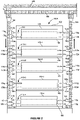
- FIGURE 2 is a schematic view showing an example system 100A that includes the first and second inlet connectors 140a,140b and first and second outlet connectors 142a,142b of primary cooling loop 110 and computing device 120 on a shelf 160 of a computing device rack 162.
- a plurality of other computing devices 120-1,120-2,120-3,120-4 and cooling loop assemblies 110-1, 110-2,110-3,110-4 are also shown on shelves 160 of the computing device rack 162.
- the computing device rack 162 in this example is one in a series of three computing device racks, as shown in FIGURE 3 , but in other examples, computing device rack 162 may be a single data rack connected to at least one cooling system, or may be one in a series of any number of racks connected to the at least one cooling system.
- FIGURE 2 illustrates the multiple inlet and outlet connection points to the cooling liquid source and liquid return outlet.
- the racks and computing devices are shown in one arrangement, but any arrangement may be utilized.
- a rack supply manifold 164 can extend the length of the computing device rack 162 and may be connected to a central cooling supply line 168.
- Rack supply manifold 164 can distribute cooling liquid from the central cooling liquid supply line 168 along the length of the entire rack 162 and provide a source of cooling liquid to each cooling loop assembly 110,110-1,110-2,110-3,110-4 of each respective computing device 120, 120-1, 120-2, 120-3,120-4.
- a rack return manifold 166 can similarly extend the length of the opposed side of the computing device rack 162, provide a return outlet for heated cooling liquid returning from the system, and pump liquid out of the computing device rack 162 and into a central return line 169 to return heated cooling liquid to a system source for cooling.
- the rack inlet and rack return manifolds 164,166 extend along the sides of the rack, but in other examples, one or both of the rack inlet and rack return manifolds can be positioned anywhere adjacent the computing device rack 162, including, for example, the front, rear, or on the same side of the server rack.
- First inlet connector 140a of cooling loop assembly 110 is shown joined to a first rack inlet connection point 170a on the rack supply manifold 164 and a second inlet connector 140b of the cooling loop assembly 110 is joined to a second rack inlet connection point 170b on the rack supply manifold 164.
- First inlet connectors 140c, 140e, 140g,140i of the remaining cooling loop assemblies 110-1 through 110-4 are also joined to rack supply manifold 164 at respective first rack inlet connection points 170c, 170e, 170g,170i.
- second inlet connectors 140d,140f,140h,140j are joined to rack supply manifold 164 at respective second rack inlet connection points 170d,170f, 170h,170j.
- Second outlet connector 142a of cooling loop assembly 110 is shown joined to a first rack outlet connection point 172a on the rack return manifold 166, and a second outlet connector 142b of the cooling loop assembly 110 is joined to a second rack outlet connection point 172b on the rack outlet inlet manifold 164.
- First outlet connectors 142c, 142e, 142g, 142i of the remaining cooling loop assemblies 110-1 through 110-4 are also joined to rack return manifold 166 at respective first rack outlet connection points 172c, 172e, 172g,172i.
- second outlet connectors 142d,142f,142h,142j are joined to rack return manifold 165 at respective second rack outlet inlet connection points 172d,172f, 172h,172j.
- a schematic coolant distribution system 180 comprises computing device rack 162, as one in a series of three data racks, but in other examples, any number of racks may be utilized.
- the coolant distribution system 180 can also comprise a central supply and return sub-system 181 includes a source or storage tank 182 of cooling liquid, chilling unit 184, central distribution unit 286, and central supply line 268 and central return line 269.
- the coolant distribution system 180 contains the pumping systems for coolant circulation, and cooling units to remove the heat from the coolant by transferring the heat to datacenter process water.
- System 180 can also be a standalone system that removes the heat from the coolant by transferring the heat to air through a fan coil or by transferring the heat to a refrigerant through a chiller system.
- the coolant distribution system pumps and distributes cooling liquid through the central cooling liquid inlet line 168 and into each of the rack supply manifolds 164, 164-1,164-2 and each first and second connector (not shown) of each computing device (not shown) in the respective computing device racks 162, 162-1, 162-2. Heated return cooling liquid will exit the respective computing device racks 162, 162-1, 162-2 through the respective rack return manifolds 166, 166-1,166-2 and into the central cooling liquid outlet line 169 and back to the central distribution unit 186. The central distribution unit 186 will then pump the heated return cooling liquid into the cooling unit 184 where the heated return cooling liquid will be cooled and then circulated back into the central distribution unit 186 and pumped back into the system.
- the components of the central supply and return sub-system 181 provides one example for cooling and distributing cooling liquid into the central inlet and outlet lines and throughout each of the racks 262,262-1,262-2, but numerous other examples may be used to accomplish the same features.
- the lines may run underground, additional or fewer cooling components may be used.
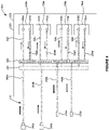
- FIGURE 4 another schematic example 200 of a cooling loop assembly 210 is shown.
- This example is otherwise similar to the example of FIGURES 1-3 , except that the first and second inlet connectors 240a,240b and the first and second outlet connectors 242a,242b, as well as the supply lines 2244a,244b, return lines 248,248b, secondary outlet lines 254a,254b,254c,254d, and the board outlet manifold 252 are positioned on the same side of the circuit board 220 of the computing device 222.
- cooling liquid from a rack supply manifold flows 264 flows through first and second inlet connectors 240a,240b and through first and second supply lines 244a,244b to the board inlet manifold 250.
- Cooling liquid is distributed from the board inlet manifold 250 to inlets 232a,232b,232c,232d of cooling devices 230a,230b,230c,230d through secondary inlet lines 246a,246b,246c,246d. Heated return cooling liquid will exit the cooling devices 230a,230b,230c,230d through their respective outlets 234a,234b,234c,234d and flow to the board outlet manifold 252. First and second return lines 248a,248b will distribute cooling liquid from the board outlet manifold 252 to connectors 242a,242b and the rack return manifold 266.
- rack supply manifold 264 and rack return manifold 266 can be positioned directly adjacent one another and on the same side of computing device 220 and/or the cooling devices.
- Cooling loop assembly 210 and computing device 220 can be positioned on a shelf of computing device rack 262.
- First and second inlet connection points 270a,270b are positioned on the rack supply manifold 264, and first and second outlet connection points 272a,272b are positioned on the rack return manifold.
- Cooling loop assembly 210 is joined to the first and second inlet connection points 270a,270b via first and second inlet connectors 242a,242b and first and second board supply lines 244a,244b. Additionally, cooling loop assembly 210 is joined to the first and second outlet connection points 272a,272b via first and second outlet connectors 242a,242b and first and second return lines 248a,248b.
- one or more similar computing devices 220-1, 220-2, 220-3, 220-4 with similar cooling loop assemblies 210-1, 210-2, 210-3, 210-4 can be provided on additional shelves 260 of a computing device rack 262, all of which are coupled to the rack supply manifold 264 and a rack return manifold 266.
- a plurality of additional first and second inlet connectors 242c-j, as well as corresponding first and second board supply lines 244c-244j are joined to the rack supply manifold 264 at respective rack inlet connection points 270c-j.
- Additional first and second outlet connectors 272c-j and corresponding first and second return lines 248c-j are also joined to the rack outlet manifold 266 at respective rack outlet connection points 272c-j.
- some of the computing devices may be connected to a separate set of rack supply and return manifolds.
- FIGURE 6 illustrates a schematic cooling distribution system 280 that comprises a computing device rack 262, as well as any number of additional computing device racks, such as computing device racks 262-1,262-2, as well as a cooling and return sub-system 181.
- the cooling and return sub-system 181 can include a cooling liquid supply or storage tank 282, a chilling system 284, a central distribution unit 286, a central supply line 268 and central return line 269.
- the components of the central supply and return sub-system 281 can be identical to the previous example and is not discussed at length in this example, but other cooling and return sub-systems may be utilized herein. For ease of illustration, the components within the computing device racks are not shown.
- Each of the computing device racks 262,262-1,262-2 include rack supply manifolds 264,264-1,264-2 and rack return manifolds 266, 266-1,266-2, positioned on the same side of the respective computing device racks 262,262-1,262-2.
- cooling liquid can be distributed to each of the computing device racks 262,262-1,262-2 through a central supply line 268, which feeds into each of the rack supply manifolds 264,264-1,264-2.
- cooling liquid can be distributed from the central supply line and rack supply manifolds into each of the computing devices through the first and second inlet connectors and board supply lines.
- Heated return cooling liquid can then travel through the return lines and outlet connectors and up through the rack return manifolds 266, 266-1,266-2 into the central return line 269.
- the heated cooling liquid can then be processed and cooled down in the components of the central supply and return sub-system 281 and recirculated through the system again.
- supply lines 244a,244b and return lines 248a,248b that extend to the rack supply manifold 264 and rack return manifold 266 are shown having example lengths, in other examples, the length of the supply and return lines can vary widely. This can allow for the cooling loop assembly 210 to be alternatively arranged on a computing device rack 160 in a similar configuration as the loop assembly 110 of FIGURES 2 and 3 .
- supply lines 244a,244b would extend to the rack supply manifold 164 of FIGURE 2 on one side of the computing device rack 160, and return lines 246a,246b having a sufficient length to extend across the circuit board 220 can reach and be connected to the rack return manifold 166 of FIGURE 2 positioned on a different side, including an opposite side of the computing device rack 162 of FIGURE 2 .
- Cooling loop assembly shown in FIGURE 1 can also be configured and positioned on a computing device rack 260 of FIGURE 5 relative to the directly adjacent rack supply manifold 264, and the rack return manifold 266.
- FIGURES 1-6 can be easily scalable and can allow for an increased number of supply and return lines. Such configurations can provide low pressure drop through the lines. Furthermore, such designs can provide for versatility in redundancy of the cooling loop designs, as will be discussed in more detail with regard to the example redundant systems described with regard to FIGURES 11-15 .
- FIGURE 7 is another example system 400 that includes a cooling loop assembly 410 where the inlet configuration differs from the previous examples.
- an inlet tee 445 can be used to join a first inlet connector 440a and a second inlet connector 440b together so as to create a branched inlet connector or connection 441.
- the first connector inlet line 436a extends between the inlet tee 445 and the first inlet connector 440a.
- a second connector inlet line 436b extends between the inlet tee 445 and the second inlet connector 440b.
- the inlet tee 445 allows for distribution of combined cooling liquid flowing from the first inlet connector 440a and the second connector 440b to the board inlet manifold 450 through a board supply line 444.
- Use of a branched inlet connection 441 can help to avoid conflicts arising from the use of additional multiple inlet lines, as well as allow for increased space by eliminating extra lines. It can allow for retrofitting from existing single supply and return designs, and also provides a configuration that allows for versatility in creating a redundant system, such as in the examples discussed below regarding FIGURES 11-15 .
- An outlet tee connector 447 can be used to join a first outlet connector 442a and a second outlet connector 442b together so as to create a branched outlet connector or connection 443.
- the first connector outlet line 438a extends between the outlet tee connector 445 and the first outlet connector 442a.
- a second connector outlet line 438b extends between the outlet tee connector 445 and the second outlet connector 442b.
- the outlet tee connector 447 allows for the distribution of heated return cooling liquid flowing from the rack return manifold 452 through the return line 454 and into the outlet tee connector 447. At the outlet tee connector 447 the heated return cooling liquid can be divided between the first connector outlet line 438a and the second connector outlet line 438b.
- cooling liquid will be pumped from a liquid source through the first and second connectors 440a,440b and through the inlet tee 445 to the board supply line 444.
- the board supply line 444 which extends from the inlet tee 445 to the board inlet manifold 450, can further distribute the combined cooling liquid entering the cooling loop assembly 400 from the first inlet connector 440a and the second inlet connector 440b to the board manifold 450.
- Cooling liquid in the board manifold 450 will be further distributed to the inlets 432a, 432b,432c,432d of the cooling devices 430a,430b,430c,430d through respective secondary inlet lines 446a,446b,446c,446d.
- Heated return cooling liquid exits the outlets 434a,434b,434c,434d of each respective cooling device 430a,430b,4340c,430d and flows to the board outlet manifold 452 through secondary outlet lines 454a,454b,454c,454d. Heated return cooling liquid will then flow from board outlet manifold 452 to the outlet tee connector 447, where the flow will then be divided between the first and second connector lines 438a,43b as the flow continues to the first and second outlet connectors 442a,442b and to an outlet, such as a rack return manifold.
- FIGURE 8 illustrates a schematic example of a rack system 400a that includes computing device 420 and cooling loop assembly 410 as part of a larger computing device rack 462, as well as branched inlets or dual inlet and dual outlet connection points to the cooling liquid source and liquid return outlet for each computing device 420-1, 420-2,420-3,420-4 on the respective shelves 460.
- the racks and computing devices are shown in one arrangement, but any arrangement may be utilized.
- rack supply manifold 464 may be connected with central supply line 468 and rack return manifold 466 can be connected to the central return line 469.
- cooling liquid can enter the rack supply manifold 464 and be distributed through the first inlet connectors 440a at the first rack inlet connection point 470a and the second inlet connector 440b at the second rack inlet connection point 470b.
- the inlet tee 445 will combine the flow of cooling liquid through the first connector line 436a and the second connector line 436b and direct the flow through the board supply line 444.
- the flow will be distributed throughout the rest of the cooling loop assembly 410 as previously described and heated return cooling liquid will exit the computing device 420 through the board return line 454.
- the outlet tee 447 will then divide the volume of the heated return cooling liquid and direct the heated return cooling liquid through the first and second outlet lines 438a,438b and outlet connectors 442a,442b and into the rack return manifold 464 through the rack connection points 470a,470b. The flow will then be distributed to the central outlet line 469.
- Additional computing devices 420-1, 420-2, 420-3 can include a similar configuration. Cooling liquid will enter the rack supply manifold 464 and be further distributed through the first inlet connectors 440c, 440e, 440g, 440i at each respective first rack inlet connection point 470c, 470e, 470g, 470i, as well as through the second inlet connectors 440c,440e,440g,440i at each respective second rack inlet connection point 470d,470f,470h,470j.
- Heated return cooling liquid will exit each of the computing devices 420-1,420-2,420-3,420-4 through the respective first outlet connectors 442c, 442e, 442g, 442i at each first rack outlet connection point 472c, 472e, 472g, 472i, as well as through the respective second outlet connectors 442d, 442f, 442h, 442j at each second rack outlet connection point 472d, 472f, 472h, 472j.
- each of the cooling loop assemblies 410-1,410-2,410-3,4104 include a similar configuration as cooling loop assembly 410 where a tee is utilized to create branched inlets and outlets, but in other examples, any of the cooing loop assembly configurations may differ, including the number of inlets and outlets and the type of connections.
- the rack 462 can also be part of a larger system of racks, as previously described with regard to FIGURES 4 and 6 .
- first and second inlet connectors 440a,440b are joined together by inlet tee 445, and the first and second outlet connectors 442a,442b are joined together by an outlet tee connector 447.
- one set of connectors may have a direct connection to a respective board manifold and the other set of connectors may include a tee connector and have an indirect connection to the respective board manifold.
- first and second inlet connectors 440a,440b may be directly joined to the board inlet manifold 450, as described in any one of the foregoing examples, and the first and second outlet connectors 442a,442b may be indirectly joined to the board outlet manifold through the outlet tee connector 447 and return line 454.
- first and second inlet connectors 440a,440b are joined together by the inlet tee 445 and indirectly connected to the board inlet manifold 450 through the board supply line 444, and the first and second outlet connectors 442a,442b are directly connected to the board outlet manifold 452.
- a single cooling loop assembly that includes an equal number of multiple inlet connection points to a single fluid inlet source and multiple outlet connection points to the fluid outlet source, when further distributing cooling liquid to and from the cooling devices through a board manifold.
- the number of inlet connection points and outlet connection points can be optimized to achieve desired thermal and mechanical properties in the cooling loop assembly, as well as the overall system. For example, the number of inlet and outlet connection points does not need to be the same and fewer inlet and/or outlet connection points can be utilized in the cooling loop assembly.
- cooling loop assembly 510 for thermal management of components and cooling devices 530a,530b,530c,530d on a circuit board 520 of a computing device 522 is shown.
- the cooling loop assembly 510 is otherwise identical to the cooling loop 210 of FIGURE 4 , except that in this example, only one outlet connector 542 is present in the cooling loop assembly 510.
- cooling loop assembly 510 includes first and second inlet connectors 540a,540b connected to a board inlet manifold 550, but only includes one outlet connector 542 that is connected to a board outlet manifold 550.
- FIGURE 10 is one example of a circuit board 622 of a computing device 620 with a first cooling loop assembly 610A and a second cooling loop assembly 710.
- the first cooling loop assembly 610 includes two inlets and one outlet.
- a branched inlet as previously disclosed, includes a first inlet connector 640a and a second inlet connector 640b joined together by an inlet tee 645.
- a single board supply line 644 connects the tee connector 445 to a board inlet manifold 650, which is connected to the cooling devices 630a,630b along secondary inlet lines 646a.646b.
- Secondary outlet lines 654a,654b extend from the cooling devices 630a,630b to the board outlet manifold 652, which in turn is connected to outlet connector 642 and outlet 626 by a single return line 648.
- cooling liquid can flow in the directions shown by the arrows.
- the second cooling loop assembly 710 includes one inlet 724 having an inlet connector 740 and two outlets 726a,726b with corresponding outlet connectors 726a,726b. Cooling liquid flows into supply line 744 through inlet 724 connector 740. Supply line 744 feeds into a board manifold 750, which is configured to distribute cooling liquid to cooling devices 730a,730b through secondary inlet lines 746a,746b. Heated return cooling liquid that exits cooling devices 730a,730b will flow through secondary outlet lines 754a,754b to the board outlet manifold 752. Return outlet lines 748,748b will distribute heated return cooling liquid from the board outlet manifold to outlet 726a,726b and connectors 742a,742b.
- cooling devices may be implemented within a cooling loop assembly of a system. In any of the examples described herein, it may be desired to include a cooling loop assembly that has only one cooling device or at least one cooling device. In other examples, at least two, at least three, or at least five cooling devices can be used in the system according to aspects of the disclosure.
- FIGURE 10A illustrates an example system 2000 that includes an example cooling loop assembly 2110 coupled to a single cooling device 2030 overlying a circuit board 2120 of a computing device 2120.
- At least three inlet connectors 2140a,2140b,2140c can be used to supply cooling liquid to the cooling device 2030, but in other examples greater or fewer inlet connectors may be used.
- three inlet connectors 2140a,2140b,2140c can be coupled to a board inlet manifold 2150 by board supply lines 2144a, 2144b, 2144c, but in other examples greater or fewer outlet connectors may be used.
- At least three outlet connectors 2142a,2142b,2142c are coupled to the cooling device 2130.
- board return lines 2148a,2148b,2148c can directly connect the outlet connectors 2142a,2142b,2142c to the board return manifold 2152, and a secondary return line 2154 couples the board return manifold 2152 to the outlet 2134 of cooling device 2130.
- board supply lines 2144a,2144b,2142c can directly connect the inlet connectors 2140a,2140b,2140c to the board inlet manifold 2150, and a secondary supply line 2146 couples the board supply manifold 2150 to the inlet 2132 of the cooling device 2130.
- the outlet connectors 2142a,2142b,2142c can directly connect to a rack return manifold (not shown) oriented on one side of the cooling device 2130, and the inlet connectors 2140a,2140b,2140c can connect directly connect to a rack supply manifold (not shown) oriented on the opposite side of the cooling device 2130.
- the rack supply and rack return manifolds may be oriented as shown in FIGURE 2 .
- FIGURE 10B shows an alternative system 2000-1 in which inlet connectors 2140a,2140b,2140c and outlet connectors 2142a,2142b,2142c are coupled to cooling device 2130 in a different configuration.
- the lines can instead be oriented so that the outlet connectors 2142a,2142b,2142c and inlet connectors 2140a,2140b,2140c, the corresponding supply lines 2144a, 2144b, 2144c, 2146 and return lines 2138a, 2148b,2148c, 2154, and the board inlet manifold 2150 and board return manifold 2152 can be joined to a rack return manifold (not shown) and a rack supply manifold (not shown) oriented on the same side of the cooling device 2130, which is also oriented on the same side of the circuit board 2122.
- the inlet connectors 2140a,2140b,2140c and outlet connectors 2142a,2142b,2142c can join to the rack supply manifold 264 and
- FIGURE 10C shows another example system 2000-2 with a branched inlet connector or connection 2241 and a branched outlet connector or connection 2243.
- the branched inlet and outlet connections can be identical to the example disclosed in FIGURE 7 and are not described in detail.
- both the inlet connectors 2240a,2240b,2240c and outlet connectors 2242a,2242b,2242c are positioned on one side or the same side of the cooling device 2230. Since only one cooling device 2130 is provided on the system, a board supply line 2244 can directly connect the branched inlet connector 2241, including inlet connectors 2240a,2240b and the inlet tee 2145, to the inlet 2232 of the cooling device 2230.
- a board return line and a board return line 2254 can couple or directly connect the branched outlet connectors 2243, including outlet connectors 2242a,2242b and outlet tee 2247, to the outlet 2234 of the cooling device 2230.
- This can allow for connection to a rack supply manifold and a rack return manifold positioned on the same side of the cooling device, as in prior examples.
- either one of the inlet connectors and outlet connectors may be positioned on an opposite side of the cooling device 2230. This can allow for connection to a rack supply manifold and a rack return manifold positioned on opposite sides of the cooling device, as in prior examples.
- FIGURE 11 illustrates an example system 800 that includes a circuit board 822 of a computing device 820, cooling devices 830a,830b,830c,830d, and two cooling loop assemblies, a first cooling loop assembly 810 and a second cooling loop 910.
- each of the first and second loop assemblies 810,910 has an independent assembly source inlet manifold and an assembly outlet manifold.
- Both the first and second cooling loop assemblies 810, 910 can feed cooling liquid into and out of the same cooling devices 830a,830b,830c,830d.
- the other cooling loop which has a separate liquid source, remains in operation, thereby allowing for redundancy of the system.
- the two cooling loop assembles are disposed on opposed sides of the cooling devices 830a,830b,830c,830d, but the cooling loops can remain in fluid communication in any configuration relative to the cooling devices 830a,830b,830c,830d.
- First cooling loop assembly 810 is positioned on the left side of the circuit board 822, whereas the second cooling loop assembly 910 is positioned on the right side of the circuit board 822.
- the first cooling loop assembly 810 is similar to the cooling loop assembly 110 previously described with regards to FIGURE 4 . Similar reference numerals will be used to identify similar components and a full discussion is not repeated here.
- the inlets 826a,826b, including first and second inlet connectors 840a,840b of the first cooling loop assembly 810 can be connected to a first cooling liquid supply source that is external to the circuit board, such as a rack supply manifold (not shown) via first and second connectors 840a,840b.
- the outlets 826a,826b, including first and second outlet connectors 842a,842b are similarly connected to an outlet external to the circuit board 822, such as rack return manifold (not shown).
- Second cooling loop assembly 910 is a redundant cooling loop assembly that is a mirror image of first cooling loop assembly 810 and operates in a similar way and where similar reference numerals will be used to identify similar features. Cooling liquid flowing toward cooling devices 830a,830b,830c and in the inflow direction are illustrated with a dotted pattern.
- the outlets 824a,825 of the second cooling loop assembly 910, including first and second outlet connectors 940a,940b, are connected to a redundant and second cooling liquid supply source that is external to the circuit board, such as a rack supply manifold 964 ( FIGURE 12 ).
- the outlets 926a,926b are connected to a second assembly outlet, such as rack return manifold 966 ( FIGURE 12 ). Heated return cooling liquid flowing away from cooling devices 830a,830b,830c and in the outflow direction are illustrated with a diamond pattern.
- cooling devices 830a,830b,830c,830d include dual inlets and outlets, although in other examples the devices include only a single inlet and a single outlet.
- cooling devices 830a,830b,830c,830d have first cooling device inlets 832a,832b,832c,832d and respective second cooling device inlets 932a,932b,932c,932d, as well as respective first cooling device outlets 834a,834b,834c,834d and respective second cooling device outlets 934a,934b,934c,934d.
- first cooling device inlets 832a,832b,832c,832d are respectively connected to secondary supply lines 846a,846b,846c,846d of the first cooling loop assembly 810.
- the second cooling device inlets 932a,932b,932c,932d are respectively connected to secondary supply lines 846a,846b,846c,846d of the second cooling loop assembly 910.
- first cooling device outlets 834a,834,834c,834d are connected to respective secondary return lines 854a,854b,854c,854d of the first cooling loop assembly 810.
- Second cooling device outlets 934a,934b,934c,934d are respectively connected to secondary return lines of the second cooling loop assembly 910.
- cooling liquid flows into the first inlets 832a,832b,832c,832d and second inlets 932a,932b,932c,932d of the respective cooling devices 830a,830b,830c,830d from cooling liquid supplied by both the first cooling loop 810 and the second cooling loop 910. Cooling liquid will flow through the first and second inlet connectors 840a,840b of the first loop assembly 810 to the respective cooling devices 830a,830b,830c,830d.
- cooling liquid will flow through the first and second board supply lines 844a,844b, to the board supply manifold 850, and through respective secondary supply lines 846a,846b,846c,846d to respective first inlets 832a,832b,832c,832d of the respective cooling devices 830a,830b,830c,830d.
- a second source of cooling liquid will flow through the first and second inlet connectors 940a,940b of the second loop assembly 910 to the respective second inlets 932a,932b,932c,932d of the respective cooling devices 830a,830b,830c,830d.
- cooling liquid will flow through the first and second board supply lines 944a,944b, to the board supply manifold 950, and through respective secondary supply lines 946a,946b,946c,946d to respective second inlets 932a,932b,932c,932d.
- Cooling liquid within each of the cooling devices 830a,830b,830c,830d will then exit from the respective cooling device through first outlets 834a,834b,834c,834d and second outlets 934a,94b,934c,934d.
- cooling liquid from the first outlets 834a,834b,834c,834d will flow through secondary supply lines 854a,854b,854c,854d of the first cooling liquid assembly to the board return manifold 852, as well as through primary return lines 848a,848b and to the outlets 826a,826b through outlet connectors 826a,826b.
- Cooling liquid from the second outlets 934a,934b,934c,934d of the second loop assembly 910 will also direct flow to the outlet connectors 842a,842b.
- heated cooling liquid will flow from the respective second outlets 934a,934b,934c,934d through secondary supply lines 954a,954b,954c,954d of the second cooling assembly 910 to the board return manifold 952, as well as through primary return lines 948a,948b and through outlet connectors 926a,926b of the second loop assembly.
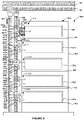
- a rack assembly 1000 which includes circuit board 822 of computing device 820 and first and second cold plate loop assemblies 810,910, is shown positioned on a top shelf 860 of a larger data rack 862, and cooling system. Additional computing devices 820-1,820-2,820-3,820-4 are positioned on additional shelves 860 within the rack 862. First cooling liquid assemblies 810-1,810,2,810-3,810-4 and the redundant second cooling liquid assemblies 910-1,910-2,910-3,91-4 are shown extending into each of the respective computing devices 820-1,820-2,820-3,820-4.
- first and second cold loop assemblies 810,916 overlap along the inlets and outlets of the cooling devices ( FIGURE 11 ), the broken line rectangles are shown overlapping.
- the rack assembly 1000 includes a first rack supply manifold 864 and a second rack supply manifold 964 that supplies cooling liquid to all computing devices 820,820-1,820-2,820-3,820-4 on the rack with supply lines attached to the respective first rack supply manifold 864 and second rack supply manifold.
- a first rack return manifold 866 and a second rack return manifold 966 provide an outlet for heated return cooling liquid exiting the respective computing devices 820,820-1,820-2,820-3,820-4 through supply lines attached to the first rack return manifold and second rack return manifold 966.
- a first central supply line 868 feeds cooling liquid into the first rack supply manifold 864 and first central return line 869 distributes return cooling liquid back to the cooling central supply and return subsystem 881 ( FIGURE 13 ).
- a second central supply line 968 feeds cooling liquid into the second rack supply manifold 964 and first central return line 969 distributes heated return cooling liquid from the second manifold 966 to the central supply and return subsystem 981 ( FIGURE 13 ).
- the first rack supply manifold 864 includes a plurality of inlets or openings along its length, including first rack inlet connection points 870a, 870c,870e,870g,870i and plurality of second rack inlet connection points 870b,870d,870f,870h,870j.
- the first rack return manifold 866 similarly includes a plurality of openings along its length, including first rack outlet connection points 872a, 872c,872e,872g,872i and a second rack outlet connection points 872b,872d,872f,872h,872j.
- the second rack supply manifold 964 and return manifold 966 are redundant manifolds that provide a secondary or redundant source of cooling liquid for each computing device on the shelves 860, and allow for distribution of heated return cooling liquid from a separate cooling liquid source, as discussed in more detail in FIGURE 13 .
- the second rack supply manifold 864 includes a plurality of inlets or openings along its length to allow for connection of supply lines to the manifold, including first rack inlet connection points 970a, 970c, 970e,970g,970i and plurality of second rack inlet connection points 970b,970d,970f,970h,970j.
- the first rack return manifold 966 similarly includes a plurality of openings along its length to allow for connection of return lines to the manifold, including first rack outlet connection points 972a, 972c, 972e,972g,972i and a second rack outlet connection points 972b,972d,972f,972h,972j.
- the first cooling loop assembly 810 is connected to the first rack supply manifold 864 and rack return manifold 866.
- the first inlet connector 840a of the first cooling loop assembly 810 is joined to the first connection points 870a on the first rack supply manifold 864 and the second inlet connector 840b of the first cooling loop assembly 810 is connected to the second connection point 870b.
- This provides for fluid communication between the first rack supply manifold 864 and the first cooling loop assembly 810.
- the first outlet connector 842a is connected to the first outlet connection point 872a and second outlet connector 842b is connected to the second outlet connection point 872b on the first rack return manifold 866. This allows for fluid communication between the first rack return manifold 864 and the first cooling loop assembly 810.
- the second cooling loop assembly 910 is connected to the second rack supply manifold 964 and second rack return manifold 966.
- the second rack supply manifold 964 provides a redundant cooling liquid supply to the second cooling loop assembly 910.
- the first inlet connector 940a of the second cooling loop assembly 910 is joined to the first connection points 970a on the second rack supply manifold 964 and the second inlet connector 940b of the second cooling loop assembly 910 is connected to the second connection point 970b. This provides for fluid communication between the redundant and second rack supply manifold 964 and the second cooling loop assembly 910.
- first outlet connector 942a is connected to the first outlet connection point 972a and second outlet connector 942b is connected to the second outlet connection point 972b on the second rack return manifold 966. This allows for fluid communication between the second rack return manifold 864 and the second cooling loop assembly 910.
- Each of the remaining computing device 820-1,820-2,820-3,820-4 includes respective first cooling loop assemblies 810-1,810-2,810-3,810-4 and redundant and second cooling loop assemblies 910-1,910-2,910-3,910-4 that include similar structure and operate in a manner identical to computing device 820.
- each of the first cooling loop assemblies 810-1,810-2,810-3,810-4 are connected to the first rack supply manifold 864 and the first rack return manifold 866 as described with regard to the first cooling loop 810 and are not further described in detail.
- Second cooling loops assemblies 910-1,910-2,910-3,910-4 are also similarly attached to the second rack supply manifold 964 and second return manifold 966 as described with regard to the second cooling loop 810 and are not further described in detail. In other examples, the cooling loop assemblies used in the system may vary.
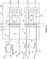
- the redundant system 1100 includes a first central supply and return subsystem 881 and a redundant and second central supply and return subsystem 981.
- the first subsystem 881 provides for circulation of cooling liquid into each of the computing device racks 862,862-1 and out of the computing device racks 862,862-1.
- the subsystem 881 supplies cooling liquid to the first rack supply manifolds 864,864-1 and the first cooling loop assemblies and returns the heated return cooling liquid from the second cooling loop assemblies through the first rack return manifolds 866,866-1.
- the first supply and first return manifolds are shown positioned on the left side of the computing device racks 862,862-1.
- This second subsystem provides a redundant supply of cooling liquid through the redundant and second supply manifolds 964,964-1 to the second cooling loop assemblies of the computing device racks 862,862-1.
- heated return cooling liquid exiting the second cooling loop assemblies of the computing devices in the respective racks 862,862-1 flow through the second return manifolds 966, 966-1.
- the components of the second subsystem 981 may be independent of the first subsystem 881 to the extent that it includes its own set of system components and operates on a loop that is independent of the loop in the first subsystem 881.
- this system ensures that even if one of the components in the first subsystem 881 fails, such as the central distribution unit 886, the redundant supply and return provided by the second subsystem 981 will ensure that the components within the computing devices are continually cooled. In a scenario where the central distribution unit 886 fails, the computing devices within the computing devices racks 862,862-1 would overheat without the presence of the subsystem 981. In other examples, one or more components of the first and second subsystems 881,981 may be shared.
- a water source 882 may pump a cooling liquid, such as water, into cooling unit 884.
- Cooling unit 884 can be any conventional cooling unit 184 capable of cooling water within the unit to a pre-set temperature. Water from cooling unit 884 will then be pumped into the central distribution unit 886, which will further pump and distribute cooling liquid through the central cooling liquid inlet line 868 and into each of the first rack supply manifolds 964, 864-1 and into each of the first and second connectors (not shown) of each computing device (not shown) in the respective computing device racks 862, 862-1.
- Heated return cooling liquid will exit the respective computing device racks 862, 862-1 through the respective first rack return manifolds 866, 866-1 and into the central cooling liquid outlet line 869 and back to the central distribution unit 886.
- the CDU will then pump the heated return cooling liquid into the cooling unit 884 where the heated return cooling liquid will be cooled and then circulated back into the central distribution unit 886 and pumped back into the system.
- the central supply and return sub-system 881 provides one method and components for providing, cooling, and distributing the cooling liquid into the central inlet and outlet lines, and numerous other examples may be used to accomplish the same function.
- the lines may run underground, additional or fewer cooling components may be used.
- a water source 982 may pump a cooling liquid, such as water, into cooling unit 984.
- Cooling unit 984 can be any conventional cooling unit 984 capable of cooling water within the unit to a pre-set temperature. Water from cooling unit 984 will then be pumped into the central distribution unit 986, which will further pump and distribute cooling liquid through the central cooling liquid inlet line 968 and into each of the first rack supply manifolds 964, 964-1 and into each of the first and second connectors (not shown) of each computing device (not shown) in the respective computing device racks 962, 962-1.
- Heated return cooling liquid will exit the respective computing device racks 962, 962-1 through the respective first rack return manifolds 966, 966-1 and into the central cooling liquid outlet line 969 and back to the central distribution unit 986.
- the CDU will then pump the heated return cooling liquid into the cooling unit 984 where the heated return cooling liquid will be cooled and then circulated back into the central distribution unit 986 and pumped back into the system.
- the central supply and return sub-system 981 provides one method and components for providing, cooling, and distributing the cooling liquid into the central inlet and outlet lines, and numerous other examples may be used to accomplish the same function.
- the lines may run underground, additional or fewer cooling components may be used.
- first and second subsystems 810,910 are identical in this example, they may differ in other examples or applications.
- FIGURE 14 is an assembly 1800 that is a variation of the assembly 800 shown in FIGURES 11-13 .
- the first cooling loop assembly 1810 only includes one inlet connector 1840 and one outlet connector 1842.
- the second cooling loop assembly 1910 only includes one inlet connector 1940 and one outlet connector 1942.
- the assembly 1800 is identical to assembly 800, such that the first and second cooling loop assemblies 1810,1910 are identical to the assemblies of FIGURES 11-13 and operate in the same manner.
- FIGURE 15 shows an example system that incorporates the system 1800 of FIGURE 14 into a computing device rack system 2000.
- the system is otherwise similar to FIGURE 12 , and includes computing devices 1820,1820-1,1820-2,1820-3,1820-4 on shelves 1860 of the computing device rack 1862.
- the first loop assemblies 1810,1810-1,1810-2,1810-3,1810-4 are connected to the first rack supply manifold 1864 and the first rack return manifold 1866.
- second loop assemblies 1910,1910-1,1910-2,1910-3,1910-4 are connected to the second rack supply manifold 1964 and the second rack return manifold 1966.
- the remaining components in the system are otherwise identical to the previous examples disclosed herein, including, for example, the configuration of the computing device rack system and the overall cooling distribution system respectively shown in FIGURES 11 through 13 .
- FIGURES 11 through 15 provide a configuration that allows for multiple supply and return connectors for each computing device rack. Less pressure drop can be achieved across the systems, as well as enable rack level coolant supply redundancy. Furthermore, it is to be appreciated that redundant systems can incorporate any loop assembly configurations disclosed herein, as well as variations thereof.
- FIGURES 1-15 Numerous variations of the aforementioned examples discussed in FIGURES 1-15 are within the scope of the disclosure.
- any number of inlet connectors, outlet connectors, supply lines, return lines, secondary lines and manifolds may be utilized in various configurations relative to one or more cooling devices.
- the cooling devices may be further arranged in series, as opposed to being parallel to one another.
- the rack supply and rack return manifolds may be provided on any side of the computing device rack, and any number of rack supply and rack return manifolds may be utilized.
- the number of rack supply and rack return manifolds in the system does not need to be equal, such that there may be more rack supply manifolds than rack return manifolds, and vice versa.
- the computing devices in computing device racks in at least FIGURES 2 , 5 , 8 , 12 and 15 are not limited to the example cooling loops 110 to 110-4, 210 to 210-4, 410 to 410-4, 810 to 810-4 used in the respective computing devices.
- all of the supply and return lines, secondary lines, and board manifolds within the cooling loop assembly may utilize lines that may vary in length so as to reach and connect with the rack supply manifold and rack return manifold. This allows for one cooling loop assembly to connect with any number of rack supply and rack return manifolds in various configurations.
- the supply and return lines of the cooling loop assemblies of FIGURES 1 , 4 , 7 , 10 , 10A-10C and 11 can be flexible, to allow for connection to the rack supply manifolds (864,964,1864,1964) and rack return manifolds (866,966,1866,1966) of respective FIGURES 12 and 15 .
- this makes it possible to use smaller connectors on the rack manifold, which makes it easier for rack manifold manufacturing, reliability, and serviceability. Moreover, with small connectors in the system, lower force is required to connect and disconnect the quick disconnect couplings.
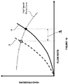
- FIGURE 16 is a system chart comparing the pressure drop to flow rate of two systems.
- Curve A represents the flow rate to pressure for a system with only a single supply and return connections to a single cooling loop for each computing device on a shelf of a computing device rack. As shown, the higher the flow rate, the greater pressure that is required to move the fluid through the system.
- Curve B represents a system curve for a system that utilizes multiple inlet/outlet connections to a single loop for an individual circuit board of a computing device on a shelf such as the concepts and examples disclosed in FIGURES 1-14 . As shown, increasing the number of connections and inlets at the shelf level reduces the pressure drop.
- an increase ⁇ in flow rate can therefore be achieved in a system with multiple inlet connections and outlet connections to a single loop, as compared to the flow rate of a system utilizing conventional single inlet and outlet connections to a single loop.
- using a system that utilizes multiple supply and return connections at the shelf level and to a single circuit board and loop can achieve increased flow rate at lower pressure for the overall system.
- the Head-Pressure curve to flow rate curve is identical to FIGURE 16 , except that a lower speed pump curve has also been added.
- Curve A single inlet/outlet connections to a single loop for each board on a shelf in the system
- Curve B multiple inlet/outlet connections to a single loop for each board on a shelf in the system
- power-flow rate curve this also means that less power is required to achieve the same flow rate. This amounts to a cost savings on cost to run the system, as well as wear and tear on the components utilizing the system. Further, smaller pumps can be utilized in the system design to save on overall cost.
- the present disclosure provides a system including a central supply line and a central return line connected to a fluid source of cooling liquid.
- a rack supply manifold is connected to the central supply line.
- a rack return manifold is connected to the central return line.
- a liquid cooling loop assembly may be coupled to at least one cooling device connected to a circuit board.
- Multiple inlet connectors may be connected to the rack supply manifold.
- Multiple outlet connectors may be connected to the rack return manifold.
- the multiple inlet connectors provide a passageway for the cooling liquid from the central supply line into the liquid cooling loop assembly for distribution to the at least one cooling device.
- the multiple outlet connectors provide a passageway to the rack return manifold for the cooling liquid exiting the at least one cooling device.
Landscapes
- Engineering & Computer Science (AREA)
- General Engineering & Computer Science (AREA)
- Physics & Mathematics (AREA)
- Computer Hardware Design (AREA)
- Thermal Sciences (AREA)
- Microelectronics & Electronic Packaging (AREA)
- Theoretical Computer Science (AREA)
- Human Computer Interaction (AREA)
- General Physics & Mathematics (AREA)
- Cooling Or The Like Of Electrical Apparatus (AREA)
Abstract
Description
- This application relates to the field of electronics, and particularly thermal management and cooling of chip assemblies utilizing liquid cooling. Liquid cooling can be used within computing equipment and on data center racks to aid in the reduction of heat generated by microelectronic elements within the chip assemblies, as well as heat generated by components external to the assembly.
- Corporations operating large-scale computing systems invest significant amounts of capital to establish and maintain the equipment comprising the computing systems. These computing systems are typically stored in data centers, which require expensive hardware and equipment, as well as real estate and personnel to maintain the equipment stored in the data centers. To minimize costs, data center racks and the equipment thereon are designed to be compact and capable of functioning over extended periods of time, as well as modular to accommodate changing architecture and configuration of components within the computing system.
- Given the high power outputs of each computing system, as well as the other equipment in the data rack and in the data center, high levels of heat are generated. Significant heat within and around the computing systems threaten the lifespan and operation of the computing system.
- Liquid cooling is one method in which to remove heat in the system and to maintain components, such as chip assemblies and microprocessors, within the system within operating temperature limits. Liquid cooling allows for removal of the excess heat with heat transfer fluid pumped into a cooling device and the heated return cooling liquid pumped out of the device.
- According to aspects of the disclosure, a system for thermal management of computing devices comprises a central supply line coupled to a fluid source of cooling liquid; a central return line coupled to the fluid source; a rack supply manifold coupled to the central supply line; a rack return manifold coupled to the central return line; and a loop assembly coupled to the rack supply manifold and the rack return manifold. The cooling loop assembly can be coupled to at least one cooling device that is electrically connected to a circuit board, the cooling loop assembly further comprising multiple inlet connectors connected to the rack supply manifold; and multiple outlet connectors connected to the rack return manifold. The multiple inlet connectors may provide a passageway for the cooling liquid from the central supply line into the cooling loop assembly for distribution to the at least one cooling device. The multiple outlet connectors may provide a passageway to the rack return manifold for the cooling liquid exiting the at least two of the cooling devices.
- In one example, each multiple inlet connector may be coupled to a board supply line that feeds fluid from the rack supply manifold into the cooling loop assembly and into the at least one cooling device. The cooling loop assembly can further comprise a board inlet manifold and secondary supply lines. The secondary supply lines may connect the board inlet manifold to the at least one cooling device.
- In another example, the cooling loop assembly can additionally or alternatively comprise board return lines coupled to each multiple outlet connector. The cooling liquid may return from the at least one cooling device flows through each of the board return lines and the multiple outlet connectors. Additionally or alternatively, the cooling loop assembly can comprise a board outlet manifold and secondary return lines connecting the multiple outlet connectors to the board outlet manifold.
- In another example, the at least one cooling device is two or more cooling devices, and the multiple inlet connectors are at least two inlet connectors. Additionally, in some examples, the multiple outlet connectors may be at least two outlet connectors. In some examples, the rack supply manifold and the rack return manifold may be positioned on opposed sides of the two or more cooling devices. In other examples, the rack supply manifold and the rack return manifold are positioned on a same side of the two or more cooling devices.
- According to another example of this aspect, the multiple inlet connectors and the multiple outlet connectors are first multiple inlet connectors and first multiple outlet connectors. The cooling loop assembly may be a first cooling loop assembly and the system may further include a second cooling loop assembly coupled to the rack supply manifold and rack return manifold. The first cooling loop assembly may overlie the second cooling loop assembly. The second cooling loop assembly may be coupled to at least one other cooling device connected to another circuit board.
- In another example, the rack supply manifold may be a first rack supply manifold and the rack return manifold may be a first rack return manifold. The system may further comprise a second central supply line; a second central return line; a second rack supply manifold coupled to the second central supply line; and a second rack return manifold coupled to the second central return line. At least one of the multiple inlet connectors may be connected to the second rack supply manifold. At least one of the multiple outlet connectors may be connected to the second rack return manifold. The at least one of the multiple inlet connectors may provide a passageway for the cooling liquid from the second central supply line into the cooling loop assembly for distribution to the at least one cooling device. The at least one of the multiple outlet connectors provide a passageway to the second rack return manifold for the cooling liquid to exit the at least one of the cooling devices.
- The multiple inlet connectors and the multiple outlet connectors may comprise quick disconnect couplings.
- According to another aspect of the disclosure, a system comprises a circuit board; a plurality of microelectronic assemblies electronically connected to the circuit board; a plurality of cooling devices; and a cooling loop assembly. The plurality of cooling devices may overlie a first microelectronic assembly and a second microelectronic assembly of the plurality of microelectronic assemblies and be configured to cool the first and second microelectronic assemblies. The cooling loop assembly may be coupled to the plurality of the cooling devices and overlie the circuit board. The cooling loop assembly can comprise multiple inlet connectors configured to be coupled to an assembly fluid source external to the circuit board; and multiple outlet connectors configured to be coupled to an assembly return line external to the circuit board. The multiple inlet connectors provide a passageway for cooling liquid from the assembly fluid source into the cooling loop assembly for distribution to the at least two of the cooling devices. The multiple outlet connectors may provide a passageway to the assembly return line for the cooling liquid exiting the at least two of the cooling devices.
- In one example, each of the multiple inlet connectors is attached to a board supply line overlying the circuit board and that feeds fluid into the cooling loop assembly and into the at least two of the cooling devices. Additionally, an outlet return line may overlie the circuit board and be connected to each of the multiple outlet connectors. The cooling liquid returning from each of the at least two of the cooling devices may flow through each of the outlet return lines and the multiple outlet connectors. Additionally, the inlet connectors and outlet connectors are quick disconnect couplings and the outlet connectors are quick disconnect couplings.
- According to another aspect of the disclosure, a system for thermal management of computing devices comprises a rack supply manifold connected to a supply line; a rack return manifold connected to a central return line; and a first cooling loop assembly and a second cooling loop assembly coupled to the rack supply manifold and the rack return manifold. The first cooling loop assembly may be coupled to at least one cooling device that is electrically connected to a circuit board. The first cooling loop assembly comprises at least one inlet connector coupled to the rack supply manifold. The at least one inlet connector provides a passageway for cooling liquid from the rack supply manifold into the first cooling loop assembly for distribution to the at least one cooling device. At least one outlet connector may be coupled to the rack return manifold. The at least one outlet connector may provide a passageway for cooling liquid exiting the at least one cooling device to the rack return manifold. At least one of the at least one inlet connector and the at least one outlet connector is a plurality of inlet connectors or outlet connectors. The second cooling loop assembly may be coupled to at least one other cooling device connected to the circuit board. The second cooling loop assembly may comprise at least one inlet connector of the second cooling loop assembly coupled to the rack supply manifold; and at least one outlet connector of the second cooling loop assembly coupled to the rack return manifold. The at least one inlet connector may provide a passageway for the cooling liquid from the rack supply manifold into the second cooling loop assembly for distribution to the at least one other cooling device. The at least one outlet connector may provide a passageway to the rack return manifold for the cooling liquid exiting the at least one other cooling device. At least one of the at least one inlet connector and the at least one outlet connector of the second cooling loop assembly is a plurality of inlet connectors or outlet connectors.
- In one example, the at least one connector of the first cooling loop assembly and the at least one connector of the second cooling loop assembly comprise a plurality of inlet connectors.
- The accompanying drawings are not intended to be drawn to scale. Similar reference numbers and designations in the various drawings indicate like elements. For purposes of clarity, not every component may be labeled in every drawing. In the drawings:
-
FIGURE 1 is a schematic top view of an example system comprising a computing device and cooling loop assembly according to aspects of the disclosure; -
FIGURE 2 is a schematic front view of an example system comprising the computing device and cooling loop assembly ofFIGURE 1 implemented within an example computing device rack, according to aspects of the disclosure; -
FIGURE 3 is a schematic front view of an example cooling system that implements the computing device and cooling loop assembly ofFIGURE 2 according to aspects of the disclosure; -
FIGURE 4 is a schematic top view of an example system comprising a computing device and cooling loop assembly according to aspects of the disclosure; -
FIGURE 5 is a schematic front view of an example system comprising the computing device and cooling loop assembly ofFIGURE 4 implemented within an example computing device rack, according to aspects of the disclosure; -
FIGURE 6 is a schematic front view of an example cooling system that implements the computing device and cooling loop assembly ofFIGURE 5 ; -
FIGURE 7 is a schematic top view of an example system comprising a computing device and cooling loop assembly according to aspects of the disclosure; -
FIGURE 8 is a schematic front view of an example system comprising the computing device and cooling loop assembly ofFIGURE 7 implemented within an example computing device rack, according to aspects of the disclosure; -
FIGURE 9 is a schematic top view of an example system comprising a computing device and an example cooling loop assembly; -
FIGURE 10 is a schematic top view of an example system comprising a computing device and an example cooling loop assembly; -
FIGURE 10A is a schematic top view of an example system comprising a computing device and cooling loop assembly according to aspects of the disclosure; -
FIGURE 10B is a schematic top view of an example system comprising a computing device and cooling loop assembly according to aspects of the disclosure; -
FIGURE 10C is a schematic top view of an example system comprising a computing device and cooling loop assembly according to aspects of the disclosure; -
FIGURE 11 is a schematic example of a top view of a computing device with two cooling loop assemblies according to aspects of the disclosure; -
FIGURE 12 is a schematic top view of an example system comprising the computing device and cooling loop assembly ofFIGURE 11 implemented within an example computing device rack, according to aspects of the disclosure; -
FIGURE 13 is a schematic front view of a cooling system comprising the computing device and cooling loop assembly ofFIGURE 4 ; -
FIGURE 14 is a schematic top view of an example computing device with two cooling loop assemblies according to aspects of the disclosure; -
FIGURE 15 is a schematic front view of an example system comprising the computing device and cooling loop assembly ofFIGURE 14 implemented within an example computing device rack, according to aspects of the disclosure; -
FIGURE 16 is a head versus flow rate graph illustrating differences between prior art cooling systems and aspects of the disclosure; and -
FIGURE 17 is a head versus flow rate graph and a power versus flow rate chart illustrating differences between prior art cooling systems and aspects of the disclosure. - Liquid cooling systems and cold plates are used to dissipate heat within chip assemblies, computing systems, and data server rack systems. Liquid cooled processors require higher coolant flow rate to maintain the computing performance and system reliability. As chip power increases, liquid flow rate must also increase to keep up with increased heat created by the chips. This can lead to significant rise in pressure drop through connections for cooling loop assemblies. Further, pumping power consumed by pressure drop in connectors does not contribute to cooling.
- To address the shortcomings associated with supplying a higher flow rate at increased power and cost, an improved liquid cooling system is disclosed. In accordance with aspects of the disclosure, the improved cooling system can include a single cooling loop with multiple quick disconnects provided at the supply interface and multiple disconnects provided at the return interface. This allows for the lowest pressure drop through the connections and the cooling loop, versatility, and a design that is easily scalable for increased number of supply and returns. Additionally, it can prevent mechanical conflict in the machine due to prior art single supply and return hoses.
-
FIGURE 1 is anexample system 100 that includes acooling loop assembly 110 with multiple inlets and multiple outlets for thermal management and liquid cooling of microelectronic assemblies, including chips, such as semiconductor chips, or other devices (not shown) on acircuit board 120 of acomputing device 122. Thecircuit board 120 may include a motherboard, main board or the like. In this example, the coolingloop assembly 110 may be the only loop implemented on thecircuit board 120 for cooling all components connected to thecooling loop assembly 110 on thecircuit board 120, but thecooling loop assembly 110 can be implemented with other loops on thecircuit board 120, as well. In this example, coolingloop assembly 110 is fluidly connected to each of thecooling devices circuit board 120. Eachcooling device respective inlet corresponding outlet loop assembly 110 andcorresponding computing device 122 may be one of a plurality of cooling loops and computing devices in a data center server rack (seeFIGURE 2 ), but in other examples the cooling loop may be utilized for a standalone individual computing device and cooling loop. - Cooling
loop assembly 110 may include at least two inlet connectors: afirst inlet connector 140a and asecond inlet connector 140b, but a single inlet connection or more than two inlet connectors may also be utilized. Coolingloop assembly 110 further includes at least two outlet connectors: afirst outlet connector 142a and asecond outlet connector 142b, but a single outlet connector or more than two outlet connectors may also be utilized. In this example, first andsecond inlet connectors FIGURE 3 ), and first and second outlet connectors may be coupled or connected to a single liquid cooling outlet or manifold (not shown in this view). - The first and
second inlet connectors second outlet connectors - A first
board supply line 144a connects thefirst inlet connector 140a to theboard inlet manifold 150 and a secondboard supply line 144b connects thesecond inlet connector 140b to theboard inlet manifold 150. Cooling liquid is distributed across thecircuit board 120 along a length of theboard inlet manifold 150. This enables cooling liquid to reach and be distributed to each of thecooling devices board inlet manifold 150 is positioned adjacent at least one of the edges of each of thecooling devices board inlet manifold 150 can be positioned anywhere on thecircuit board 120 and may be any shape or size.Secondary supply lines board inlet manifold 150 to theinlets respective cooling device - A
first return line 148a joins thefirst outlet connector 142a to theboard outlet manifold 152 and asecond return line 148b joins thesecond outlet connector 142b to theboard outlet manifold 152. Theboard outlet manifold 152 can run parallel to theboard inlet manifold 150 and in this example, extends along a length L of the circuit board and adjacent at least one edge of each of thecooling devices Secondary return lines board outlet manifold 152 and each of theoutlets respective cooling devices - The supply and return lines, as well as any secondary supply and return lines and manifolds may be hoses, pipes, or other structures that enable fluid to move from a liquid source through the inlet connections, through the cooling loop assembly and cooling devices, and back out through the return lines to an outlet. In some examples, the supply and return lines may be flexible hoses or pipes to allow for easier user handling. In other examples, the supply and return lines may be more rigid to better allow for automation of the connection and disconnection of the return and supply lines. In still other examples, the system may incorporate both flexible and rigid lines.
- The
cooling devices cooling devices cooling devices cooling devices - The
loop assembly 110 may continually pump cooling liquid through the inlet supply lines and heated return cooling liquid through the outlet lines. The cooling liquid may be any known cooling liquid from a continuous source of cooling liquids or a chiller system. Cooling liquid may include, for example, water, deionized water, inhibited glycol and water solutions, dielectric fluids, and any suitable cooling liquid. - During operation, cooling liquid from a primary source, such as a rack supply manifold 164 (see
FIGURE 2 ), can enter theloop assembly 110 through the first and second inlets of theloop assembly 110 at the first and secondquick disconnects board supply lines board inlet manifold 150, and into each of thesecondary inlet lines secondary inlet lines inlets respective cooling devices cooling devices cooling device cooling device outlets board outlet manifold 152 throughsecondary outlet lines board outlet manifold 152 through first andsecond return lines second outlet connectors FIGURE 2 ). It is to be appreciated that the arrows used throughout the descriptions of the various examples herein indicate a direction of flow of liquid in the respective cooling loop assemblies. -
FIGURE 2 is a schematic view showing anexample system 100A that includes the first andsecond inlet connectors second outlet connectors primary cooling loop 110 andcomputing device 120 on ashelf 160 of acomputing device rack 162. A plurality of other computing devices 120-1,120-2,120-3,120-4 and cooling loop assemblies 110-1, 110-2,110-3,110-4 are also shown onshelves 160 of thecomputing device rack 162. Thecomputing device rack 162 in this example is one in a series of three computing device racks, as shown inFIGURE 3 , but in other examples,computing device rack 162 may be a single data rack connected to at least one cooling system, or may be one in a series of any number of racks connected to the at least one cooling system.FIGURE 2 illustrates the multiple inlet and outlet connection points to the cooling liquid source and liquid return outlet. The racks and computing devices are shown in one arrangement, but any arrangement may be utilized. - A
rack supply manifold 164 can extend the length of thecomputing device rack 162 and may be connected to a centralcooling supply line 168.Rack supply manifold 164 can distribute cooling liquid from the central coolingliquid supply line 168 along the length of theentire rack 162 and provide a source of cooling liquid to each cooling loop assembly 110,110-1,110-2,110-3,110-4 of eachrespective computing device 120, 120-1, 120-2, 120-3,120-4. Arack return manifold 166 can similarly extend the length of the opposed side of thecomputing device rack 162, provide a return outlet for heated cooling liquid returning from the system, and pump liquid out of thecomputing device rack 162 and into acentral return line 169 to return heated cooling liquid to a system source for cooling. The rack inlet and rack return manifolds 164,166 extend along the sides of the rack, but in other examples, one or both of the rack inlet and rack return manifolds can be positioned anywhere adjacent thecomputing device rack 162, including, for example, the front, rear, or on the same side of the server rack. -
First inlet connector 140a of coolingloop assembly 110 is shown joined to a first rackinlet connection point 170a on therack supply manifold 164 and asecond inlet connector 140b of thecooling loop assembly 110 is joined to a second rackinlet connection point 170b on therack supply manifold 164.First inlet connectors supply manifold 164 at respective first rack inlet connection points 170c, 170e, 170g,170i. Similarly,second inlet connectors supply manifold 164 at respective second rackinlet connection points -
Second outlet connector 142a of coolingloop assembly 110 is shown joined to a first rackoutlet connection point 172a on therack return manifold 166, and asecond outlet connector 142b of thecooling loop assembly 110 is joined to a second rackoutlet connection point 172b on the rackoutlet inlet manifold 164.First outlet connectors return manifold 166 at respective first rack outlet connection points 172c, 172e, 172g,172i. Similarly,second outlet connectors inlet connection points - With reference to
FIGURE 3 , a schematiccoolant distribution system 180 comprisescomputing device rack 162, as one in a series of three data racks, but in other examples, any number of racks may be utilized. Thecoolant distribution system 180 can also comprise a central supply andreturn sub-system 181 includes a source orstorage tank 182 of cooling liquid, chillingunit 184,central distribution unit 286, andcentral supply line 268 andcentral return line 269. Thecoolant distribution system 180 contains the pumping systems for coolant circulation, and cooling units to remove the heat from the coolant by transferring the heat to datacenter process water.System 180 can also be a standalone system that removes the heat from the coolant by transferring the heat to air through a fan coil or by transferring the heat to a refrigerant through a chiller system. - The coolant distribution system pumps and distributes cooling liquid through the central cooling
liquid inlet line 168 and into each of therack supply manifolds 164, 164-1,164-2 and each first and second connector (not shown) of each computing device (not shown) in the respective computing device racks 162, 162-1, 162-2. Heated return cooling liquid will exit the respective computing device racks 162, 162-1, 162-2 through the respectiverack return manifolds 166, 166-1,166-2 and into the central coolingliquid outlet line 169 and back to thecentral distribution unit 186. Thecentral distribution unit 186 will then pump the heated return cooling liquid into thecooling unit 184 where the heated return cooling liquid will be cooled and then circulated back into thecentral distribution unit 186 and pumped back into the system. It is to be appreciated that the components of the central supply andreturn sub-system 181 provides one example for cooling and distributing cooling liquid into the central inlet and outlet lines and throughout each of the racks 262,262-1,262-2, but numerous other examples may be used to accomplish the same features. For example, the lines may run underground, additional or fewer cooling components may be used. - Referring to
FIGURE 4 , another schematic example 200 of acooling loop assembly 210 is shown. This example is otherwise similar to the example ofFIGURES 1-3 , except that the first andsecond inlet connectors second outlet connectors supply lines 2244a,244b, return lines 248,248b,secondary outlet lines 254a,254b,254c,254d, and theboard outlet manifold 252 are positioned on the same side of thecircuit board 220 of thecomputing device 222. As shown, the flow of cooling liquid through thecooling loop 210 will follow a circular pattern, as shown by the arrows, so as to allow for cooling liquid to return to the same side of thecircuit board 220, instead of a more linear pattern from one end of the board to the other, as in the example ofFIGURES 1-3 . For example, cooling liquid from a rack supply manifold flows 264 (FIGURE 5 ) flows through first andsecond inlet connectors second supply lines board inlet manifold 250. Cooling liquid is distributed from theboard inlet manifold 250 toinlets cooling devices cooling devices respective outlets board outlet manifold 252. First andsecond return lines board outlet manifold 252 toconnectors rack return manifold 266. - As better seen in the
example rack system 200A ofFIGURE 5 , in thiscooling loop 210 configuration,rack supply manifold 264 andrack return manifold 266 can be positioned directly adjacent one another and on the same side ofcomputing device 220 and/or the cooling devices. Coolingloop assembly 210 andcomputing device 220 can be positioned on a shelf ofcomputing device rack 262. First and secondinlet connection points rack supply manifold 264, and first and secondoutlet connection points loop assembly 210 is joined to the first and secondinlet connection points second inlet connectors board supply lines loop assembly 210 is joined to the first and secondoutlet connection points second outlet connectors second return lines - As in the previous example, one or more similar computing devices 220-1, 220-2, 220-3, 220-4 with similar cooling loop assemblies 210-1, 210-2, 210-3, 210-4 can be provided on additional shelves 260 of a
computing device rack 262, all of which are coupled to therack supply manifold 264 and arack return manifold 266. A plurality of additional first andsecond inlet connectors 242c-j, as well as corresponding first and secondboard supply lines 244c-244j are joined to therack supply manifold 264 at respective rack inlet connection points 270c-j. Additional first andsecond outlet connectors 272c-j and corresponding first andsecond return lines 248c-j are also joined to therack outlet manifold 266 at respective rack outlet connection points 272c-j. In other examples, some of the computing devices may be connected to a separate set of rack supply and return manifolds. -
FIGURE 6 illustrates a schematiccooling distribution system 280 that comprises acomputing device rack 262, as well as any number of additional computing device racks, such as computing device racks 262-1,262-2, as well as a cooling andreturn sub-system 181. The cooling andreturn sub-system 181 can include a cooling liquid supply orstorage tank 282, achilling system 284, acentral distribution unit 286, acentral supply line 268 andcentral return line 269. The components of the central supply andreturn sub-system 281 can be identical to the previous example and is not discussed at length in this example, but other cooling and return sub-systems may be utilized herein. For ease of illustration, the components within the computing device racks are not shown. Each of the computing device racks 262,262-1,262-2 include rack supply manifolds 264,264-1,264-2 andrack return manifolds 266, 266-1,266-2, positioned on the same side of the respective computing device racks 262,262-1,262-2. As in the previous example, cooling liquid can be distributed to each of the computing device racks 262,262-1,262-2 through acentral supply line 268, which feeds into each of the rack supply manifolds 264,264-1,264-2. As described inFIGURE 5 , cooling liquid can be distributed from the central supply line and rack supply manifolds into each of the computing devices through the first and second inlet connectors and board supply lines. Heated return cooling liquid can then travel through the return lines and outlet connectors and up through therack return manifolds 266, 266-1,266-2 into thecentral return line 269. The heated cooling liquid can then be processed and cooled down in the components of the central supply andreturn sub-system 281 and recirculated through the system again. - Although the
supply lines return lines rack supply manifold 264 andrack return manifold 266 are shown having example lengths, in other examples, the length of the supply and return lines can vary widely. This can allow for thecooling loop assembly 210 to be alternatively arranged on acomputing device rack 160 in a similar configuration as theloop assembly 110 ofFIGURES 2 and3 . For example,supply lines rack supply manifold 164 ofFIGURE 2 on one side of thecomputing device rack 160, and return lines 246a,246b having a sufficient length to extend across thecircuit board 220 can reach and be connected to therack return manifold 166 ofFIGURE 2 positioned on a different side, including an opposite side of thecomputing device rack 162 ofFIGURE 2 . The reverse is also true. Cooling loop assembly shown inFIGURE 1 , can also be configured and positioned on a computing device rack 260 ofFIGURE 5 relative to the directly adjacentrack supply manifold 264, and therack return manifold 266. - The configurations shown in
FIGURES 1-6 can be easily scalable and can allow for an increased number of supply and return lines. Such configurations can provide low pressure drop through the lines. Furthermore, such designs can provide for versatility in redundancy of the cooling loop designs, as will be discussed in more detail with regard to the example redundant systems described with regard toFIGURES 11-15 . -
FIGURE 7 is anotherexample system 400 that includes acooling loop assembly 410 where the inlet configuration differs from the previous examples. In this example, aninlet tee 445 can be used to join afirst inlet connector 440a and asecond inlet connector 440b together so as to create a branched inlet connector orconnection 441. As shown, the firstconnector inlet line 436a extends between theinlet tee 445 and thefirst inlet connector 440a. A secondconnector inlet line 436b extends between theinlet tee 445 and thesecond inlet connector 440b. Theinlet tee 445 allows for distribution of combined cooling liquid flowing from thefirst inlet connector 440a and thesecond connector 440b to theboard inlet manifold 450 through aboard supply line 444. Use of abranched inlet connection 441 can help to avoid conflicts arising from the use of additional multiple inlet lines, as well as allow for increased space by eliminating extra lines. It can allow for retrofitting from existing single supply and return designs, and also provides a configuration that allows for versatility in creating a redundant system, such as in the examples discussed below regardingFIGURES 11-15 . - An
outlet tee connector 447 can be used to join afirst outlet connector 442a and asecond outlet connector 442b together so as to create a branched outlet connector orconnection 443. As shown, the firstconnector outlet line 438a extends between theoutlet tee connector 445 and thefirst outlet connector 442a. A secondconnector outlet line 438b extends between theoutlet tee connector 445 and thesecond outlet connector 442b. Theoutlet tee connector 447 allows for the distribution of heated return cooling liquid flowing from therack return manifold 452 through thereturn line 454 and into theoutlet tee connector 447. At theoutlet tee connector 447 the heated return cooling liquid can be divided between the firstconnector outlet line 438a and the secondconnector outlet line 438b. - During operation, cooling liquid will be pumped from a liquid source through the first and
second connectors inlet tee 445 to theboard supply line 444. Theboard supply line 444, which extends from theinlet tee 445 to theboard inlet manifold 450, can further distribute the combined cooling liquid entering thecooling loop assembly 400 from thefirst inlet connector 440a and thesecond inlet connector 440b to theboard manifold 450. Cooling liquid in theboard manifold 450 will be further distributed to theinlets cooling devices secondary inlet lines - Heated return cooling liquid exits the
outlets respective cooling device board outlet manifold 452 throughsecondary outlet lines board outlet manifold 452 to theoutlet tee connector 447, where the flow will then be divided between the first andsecond connector lines 438a,43b as the flow continues to the first andsecond outlet connectors -
FIGURE 8 illustrates a schematic example of a rack system 400a that includescomputing device 420 and coolingloop assembly 410 as part of a largercomputing device rack 462, as well as branched inlets or dual inlet and dual outlet connection points to the cooling liquid source and liquid return outlet for each computing device 420-1, 420-2,420-3,420-4 on therespective shelves 460. The racks and computing devices are shown in one arrangement, but any arrangement may be utilized. As in the previous examples,rack supply manifold 464 may be connected withcentral supply line 468 andrack return manifold 466 can be connected to thecentral return line 469. With reference to thefirst shelf 460 andcomputing device 420, cooling liquid can enter therack supply manifold 464 and be distributed through thefirst inlet connectors 440a at the first rackinlet connection point 470a and thesecond inlet connector 440b at the second rackinlet connection point 470b. Theinlet tee 445 will combine the flow of cooling liquid through thefirst connector line 436a and thesecond connector line 436b and direct the flow through theboard supply line 444. The flow will be distributed throughout the rest of thecooling loop assembly 410 as previously described and heated return cooling liquid will exit thecomputing device 420 through theboard return line 454. Theoutlet tee 447 will then divide the volume of the heated return cooling liquid and direct the heated return cooling liquid through the first andsecond outlet lines outlet connectors rack return manifold 464 through therack connection points central outlet line 469. - Additional computing devices 420-1, 420-2, 420-3 can include a similar configuration. Cooling liquid will enter the
rack supply manifold 464 and be further distributed through thefirst inlet connectors inlet connection point second inlet connectors inlet connection point first outlet connectors outlet connection point second outlet connectors outlet connection point loop assembly 410 where a tee is utilized to create branched inlets and outlets, but in other examples, any of the cooing loop assembly configurations may differ, including the number of inlets and outlets and the type of connections. Therack 462 can also be part of a larger system of racks, as previously described with regard toFIGURES 4 and6 . - In the example described, the first and
second inlet connectors inlet tee 445, and the first andsecond outlet connectors outlet tee connector 447. In other examples, one set of connectors may have a direct connection to a respective board manifold and the other set of connectors may include a tee connector and have an indirect connection to the respective board manifold. For example, the first andsecond inlet connectors board inlet manifold 450, as described in any one of the foregoing examples, and the first andsecond outlet connectors outlet tee connector 447 and returnline 454. Conversely, an opposite configuration is also possible in which the first andsecond inlet connectors inlet tee 445 and indirectly connected to theboard inlet manifold 450 through theboard supply line 444, and the first andsecond outlet connectors board outlet manifold 452. - In the previous examples, a single cooling loop assembly is disclosed that includes an equal number of multiple inlet connection points to a single fluid inlet source and multiple outlet connection points to the fluid outlet source, when further distributing cooling liquid to and from the cooling devices through a board manifold. In other example configurations, including any of the configurations being described herein, the number of inlet connection points and outlet connection points can be optimized to achieve desired thermal and mechanical properties in the cooling loop assembly, as well as the overall system. For example, the number of inlet and outlet connection points does not need to be the same and fewer inlet and/or outlet connection points can be utilized in the cooling loop assembly.
- For example, with reference to
FIGURE 9 , acooling loop assembly 510 for thermal management of components andcooling devices circuit board 520 of acomputing device 522 is shown. Thecooling loop assembly 510 is otherwise identical to thecooling loop 210 ofFIGURE 4 , except that in this example, only oneoutlet connector 542 is present in thecooling loop assembly 510. As shown, coolingloop assembly 510 includes first andsecond inlet connectors board inlet manifold 550, but only includes oneoutlet connector 542 that is connected to aboard outlet manifold 550. As shown by the arrows inFIGURE 9 , the flow of cooling liquid through theboard inlet manifold 550 and into each of thecooling devices cooling devices board outlet manifold 552 otherwise remains the same. - Multiple loop assemblies which include either or both multiple inlet connection points or multiple outlet connection points are also disclosed.
FIGURE 10 is one example of acircuit board 622 of acomputing device 620 with a first cooling loop assembly 610A and a secondcooling loop assembly 710. - The first
cooling loop assembly 610 includes two inlets and one outlet. As shown, a branched inlet, as previously disclosed, includes afirst inlet connector 640a and asecond inlet connector 640b joined together by aninlet tee 645. A singleboard supply line 644 connects thetee connector 445 to aboard inlet manifold 650, which is connected to thecooling devices Secondary outlet lines cooling devices board outlet manifold 652, which in turn is connected tooutlet connector 642 andoutlet 626 by asingle return line 648. As in the previous examples, cooling liquid can flow in the directions shown by the arrows. - The second
cooling loop assembly 710 includes oneinlet 724 having aninlet connector 740 and twooutlets corresponding outlet connectors supply line 744 throughinlet 724connector 740.Supply line 744 feeds into aboard manifold 750, which is configured to distribute cooling liquid tocooling devices secondary inlet lines cooling devices secondary outlet lines board outlet manifold 752. Return outlet lines 748,748b will distribute heated return cooling liquid from the board outlet manifold tooutlet connectors - Any number of cooling devices may be implemented within a cooling loop assembly of a system. In any of the examples described herein, it may be desired to include a cooling loop assembly that has only one cooling device or at least one cooling device. In other examples, at least two, at least three, or at least five cooling devices can be used in the system according to aspects of the disclosure.
-
FIGURE 10A illustrates anexample system 2000 that includes an examplecooling loop assembly 2110 coupled to a single cooling device 2030 overlying acircuit board 2120 of acomputing device 2120. At least threeinlet connectors inlet connectors board inlet manifold 2150 byboard supply lines outlet connectors cooling device 2130. In this example,board return lines outlet connectors board return manifold 2152, and asecondary return line 2154 couples theboard return manifold 2152 to theoutlet 2134 ofcooling device 2130. Similarly,board supply lines inlet connectors board inlet manifold 2150, and asecondary supply line 2146 couples theboard supply manifold 2150 to theinlet 2132 of thecooling device 2130. When the supply and return lines are oriented in this configuration, theoutlet connectors cooling device 2130, and theinlet connectors cooling device 2130. In some examples, the rack supply and rack return manifolds may be oriented as shown inFIGURE 2 . -
FIGURE 10B shows an alternative system 2000-1 in whichinlet connectors outlet connectors cooling device 2130 in a different configuration. The lines can instead be oriented so that theoutlet connectors inlet connectors supply lines lines board inlet manifold 2150 andboard return manifold 2152 can be joined to a rack return manifold (not shown) and a rack supply manifold (not shown) oriented on the same side of thecooling device 2130, which is also oriented on the same side of thecircuit board 2122. For example, theinlet connectors outlet connectors rack supply manifold 264 andrack return manifold 266 shown inFIGURE 5 . -
FIGURE 10C shows another example system 2000-2 with a branched inlet connector orconnection 2241 and a branched outlet connector orconnection 2243. The branched inlet and outlet connections can be identical to the example disclosed inFIGURE 7 and are not described in detail. In this configuration, both theinlet connectors outlet connectors cooling device 2230. Since only onecooling device 2130 is provided on the system, aboard supply line 2244 can directly connect thebranched inlet connector 2241, includinginlet connectors inlet 2232 of thecooling device 2230. Similarly, a board return line and aboard return line 2254 can couple or directly connect the branchedoutlet connectors 2243, includingoutlet connectors outlet tee 2247, to theoutlet 2234 of thecooling device 2230. This can allow for connection to a rack supply manifold and a rack return manifold positioned on the same side of the cooling device, as in prior examples. Alternatively, either one of the inlet connectors and outlet connectors may be positioned on an opposite side of thecooling device 2230. This can allow for connection to a rack supply manifold and a rack return manifold positioned on opposite sides of the cooling device, as in prior examples. - The use of multiple inlets and outlets, as well as multiple loop assemblies on a single circuit board can be used to create redundancy in the overall cooling system, while reducing the pressure drop at the inlet and outlet couplings/connectors.
FIGURE 11 illustrates anexample system 800 that includes acircuit board 822 of acomputing device 820,cooling devices cooling loop assembly 810 and asecond cooling loop 910. In this configuration, each of the first and second loop assemblies 810,910 has an independent assembly source inlet manifold and an assembly outlet manifold. Both the first and secondcooling loop assemblies same cooling devices - In this example, the two cooling loop assembles are disposed on opposed sides of the
cooling devices cooling devices loop assembly 810 is positioned on the left side of thecircuit board 822, whereas the secondcooling loop assembly 910 is positioned on the right side of thecircuit board 822. The firstcooling loop assembly 810 is similar to thecooling loop assembly 110 previously described with regards toFIGURE 4 . Similar reference numerals will be used to identify similar components and a full discussion is not repeated here. Theinlets second inlet connectors cooling loop assembly 810 can be connected to a first cooling liquid supply source that is external to the circuit board, such as a rack supply manifold (not shown) via first andsecond connectors outlets second outlet connectors circuit board 822, such as rack return manifold (not shown). - Second
cooling loop assembly 910 is a redundant cooling loop assembly that is a mirror image of firstcooling loop assembly 810 and operates in a similar way and where similar reference numerals will be used to identify similar features. Cooling liquid flowing towardcooling devices outlets 824a,825 of the secondcooling loop assembly 910, including first andsecond outlet connectors FIGURE 12 ). Theoutlets FIGURE 12 ). Heated return cooling liquid flowing away from coolingdevices - Each of the
cooling devices cooling devices cooling device inlets cooling device inlets cooling device outlets cooling device outlets cooling device inlets secondary supply lines cooling loop assembly 810. The secondcooling device inlets secondary supply lines cooling loop assembly 910. Similarly, firstcooling device outlets 834a,834,834c,834d are connected to respectivesecondary return lines cooling loop assembly 810. Secondcooling device outlets cooling loop assembly 910. - During operation, cooling liquid flows into the
first inlets second inlets respective cooling devices first cooling loop 810 and thesecond cooling loop 910. Cooling liquid will flow through the first andsecond inlet connectors first loop assembly 810 to therespective cooling devices board supply lines board supply manifold 850, and through respectivesecondary supply lines first inlets respective cooling devices second inlet connectors second loop assembly 910 to the respectivesecond inlets respective cooling devices board supply lines board supply manifold 950, and through respectivesecondary supply lines second inlets - Cooling liquid within each of the
cooling devices first outlets second outlets first outlets secondary supply lines board return manifold 852, as well as throughprimary return lines outlets outlet connectors second outlets second loop assembly 910 will also direct flow to theoutlet connectors second outlets secondary supply lines second cooling assembly 910 to theboard return manifold 952, as well as throughprimary return lines outlet connectors - Turning to
FIGURE 12 , arack assembly 1000, which includescircuit board 822 ofcomputing device 820 and first and second cold plate loop assemblies 810,910, is shown positioned on atop shelf 860 of alarger data rack 862, and cooling system. Additional computing devices 820-1,820-2,820-3,820-4 are positioned onadditional shelves 860 within therack 862. First cooling liquid assemblies 810-1,810,2,810-3,810-4 and the redundant second cooling liquid assemblies 910-1,910-2,910-3,91-4 are shown extending into each of the respective computing devices 820-1,820-2,820-3,820-4. - For ease of illustration, the components within the
computing device 820 are not illustrated in detail and instead portions of the firstcold loop assembly 810 and the secondcold loop assembly 910 that are positioned withincomputing device 820 are represented by a broken line rectangle. Since the first and second cold loop assemblies 810,916 overlap along the inlets and outlets of the cooling devices (FIGURE 11 ), the broken line rectangles are shown overlapping. - The
rack assembly 1000 includes a first rack supply manifold 864 and a secondrack supply manifold 964 that supplies cooling liquid to all computing devices 820,820-1,820-2,820-3,820-4 on the rack with supply lines attached to the respective first rack supply manifold 864 and second rack supply manifold. Similarly, a firstrack return manifold 866 and a secondrack return manifold 966 provide an outlet for heated return cooling liquid exiting the respective computing devices 820,820-1,820-2,820-3,820-4 through supply lines attached to the first rack return manifold and secondrack return manifold 966. A firstcentral supply line 868 feeds cooling liquid into the first rack supply manifold 864 and firstcentral return line 869 distributes return cooling liquid back to the cooling central supply and return subsystem 881 (FIGURE 13 ). A secondcentral supply line 968 feeds cooling liquid into the secondrack supply manifold 964 and firstcentral return line 969 distributes heated return cooling liquid from thesecond manifold 966 to the central supply and return subsystem 981 (FIGURE 13 ). - The first rack supply manifold 864 includes a plurality of inlets or openings along its length, including first rack
inlet connection points rack return manifold 866 similarly includes a plurality of openings along its length, including first rackoutlet connection points - The second
rack supply manifold 964 and return manifold 966 are redundant manifolds that provide a secondary or redundant source of cooling liquid for each computing device on theshelves 860, and allow for distribution of heated return cooling liquid from a separate cooling liquid source, as discussed in more detail inFIGURE 13 . The second rack supply manifold 864 includes a plurality of inlets or openings along its length to allow for connection of supply lines to the manifold, including first rackinlet connection points rack return manifold 966 similarly includes a plurality of openings along its length to allow for connection of return lines to the manifold, including first rackoutlet connection points - With reference to the
first computing device 820 in theassembly 1000, at one end of thecomputing device 820 the firstcooling loop assembly 810 is connected to the first rack supply manifold 864 andrack return manifold 866. Thefirst inlet connector 840a of the firstcooling loop assembly 810 is joined to thefirst connection points 870a on the first rack supply manifold 864 and thesecond inlet connector 840b of the firstcooling loop assembly 810 is connected to thesecond connection point 870b. This provides for fluid communication between the first rack supply manifold 864 and the firstcooling loop assembly 810. Similarly, thefirst outlet connector 842a is connected to the firstoutlet connection point 872a andsecond outlet connector 842b is connected to the secondoutlet connection point 872b on the firstrack return manifold 866. This allows for fluid communication between the first rack return manifold 864 and the firstcooling loop assembly 810. - At the other end of the
computing device 820 the secondcooling loop assembly 910 is connected to the secondrack supply manifold 964 and secondrack return manifold 966. The secondrack supply manifold 964 provides a redundant cooling liquid supply to the secondcooling loop assembly 910. As shown, thefirst inlet connector 940a of the secondcooling loop assembly 910 is joined to thefirst connection points 970a on the secondrack supply manifold 964 and thesecond inlet connector 940b of the secondcooling loop assembly 910 is connected to thesecond connection point 970b. This provides for fluid communication between the redundant and secondrack supply manifold 964 and the secondcooling loop assembly 910. Similarly, thefirst outlet connector 942a is connected to the firstoutlet connection point 972a andsecond outlet connector 942b is connected to the secondoutlet connection point 972b on the secondrack return manifold 966. This allows for fluid communication between the second rack return manifold 864 and the secondcooling loop assembly 910. - Each of the remaining computing device 820-1,820-2,820-3,820-4 includes respective first cooling loop assemblies 810-1,810-2,810-3,810-4 and redundant and second cooling loop assemblies 910-1,910-2,910-3,910-4 that include similar structure and operate in a manner identical to
computing device 820. For example, each of the first cooling loop assemblies 810-1,810-2,810-3,810-4 are connected to the first rack supply manifold 864 and the firstrack return manifold 866 as described with regard to thefirst cooling loop 810 and are not further described in detail. Second cooling loops assemblies 910-1,910-2,910-3,910-4 are also similarly attached to the secondrack supply manifold 964 andsecond return manifold 966 as described with regard to thesecond cooling loop 810 and are not further described in detail. In other examples, the cooling loop assemblies used in the system may vary. - With reference to
FIGURE 13 a schematic redundantcooling distribution system 1100 is shown that comprises computing data rack 862, as well as at least one additional computing device rack 862-1. In other examples, any number of computing device racks may be utilized in the system. Theredundant system 1100 includes a first central supply andreturn subsystem 881 and a redundant and second central supply andreturn subsystem 981. Thefirst subsystem 881 provides for circulation of cooling liquid into each of the computing device racks 862,862-1 and out of the computing device racks 862,862-1. As shown, thesubsystem 881 supplies cooling liquid to the first rack supply manifolds 864,864-1 and the first cooling loop assemblies and returns the heated return cooling liquid from the second cooling loop assemblies through the first rack return manifolds 866,866-1. The first supply and first return manifolds are shown positioned on the left side of the computing device racks 862,862-1. This second subsystem provides a redundant supply of cooling liquid through the redundant and second supply manifolds 964,964-1 to the second cooling loop assemblies of the computing device racks 862,862-1. Similarly, heated return cooling liquid exiting the second cooling loop assemblies of the computing devices in the respective racks 862,862-1 flow through thesecond return manifolds 966, 966-1. The components of thesecond subsystem 981 may be independent of thefirst subsystem 881 to the extent that it includes its own set of system components and operates on a loop that is independent of the loop in thefirst subsystem 881. With separate cooling liquid supplies in the system and separate returns, this system ensures that even if one of the components in thefirst subsystem 881 fails, such as thecentral distribution unit 886, the redundant supply and return provided by thesecond subsystem 981 will ensure that the components within the computing devices are continually cooled. In a scenario where thecentral distribution unit 886 fails, the computing devices within the computing devices racks 862,862-1 would overheat without the presence of thesubsystem 981. In other examples, one or more components of the first and second subsystems 881,981 may be shared. - The operation of the first central supply and
return subsystem 881 is identical to the examples previously described. Awater source 882 may pump a cooling liquid, such as water, intocooling unit 884.Cooling unit 884 can be anyconventional cooling unit 184 capable of cooling water within the unit to a pre-set temperature. Water from coolingunit 884 will then be pumped into thecentral distribution unit 886, which will further pump and distribute cooling liquid through the central coolingliquid inlet line 868 and into each of the firstrack supply manifolds 964, 864-1 and into each of the first and second connectors (not shown) of each computing device (not shown) in the respective computing device racks 862, 862-1. Heated return cooling liquid will exit the respective computing device racks 862, 862-1 through the respective firstrack return manifolds 866, 866-1 and into the central coolingliquid outlet line 869 and back to thecentral distribution unit 886. The CDU will then pump the heated return cooling liquid into thecooling unit 884 where the heated return cooling liquid will be cooled and then circulated back into thecentral distribution unit 886 and pumped back into the system. It is to be appreciated that the central supply andreturn sub-system 881 provides one method and components for providing, cooling, and distributing the cooling liquid into the central inlet and outlet lines, and numerous other examples may be used to accomplish the same function. For example, the lines may run underground, additional or fewer cooling components may be used. - The operation of the second central supply and
return subsystem 881 is identical to the examples previously described. Awater source 982 may pump a cooling liquid, such as water, intocooling unit 984.Cooling unit 984 can be anyconventional cooling unit 984 capable of cooling water within the unit to a pre-set temperature. Water from coolingunit 984 will then be pumped into thecentral distribution unit 986, which will further pump and distribute cooling liquid through the central coolingliquid inlet line 968 and into each of the firstrack supply manifolds 964, 964-1 and into each of the first and second connectors (not shown) of each computing device (not shown) in the respective computing device racks 962, 962-1. Heated return cooling liquid will exit the respective computing device racks 962, 962-1 through the respective firstrack return manifolds 966, 966-1 and into the central coolingliquid outlet line 969 and back to thecentral distribution unit 986. The CDU will then pump the heated return cooling liquid into thecooling unit 984 where the heated return cooling liquid will be cooled and then circulated back into thecentral distribution unit 986 and pumped back into the system. It is to be appreciated that the central supply andreturn sub-system 981 provides one method and components for providing, cooling, and distributing the cooling liquid into the central inlet and outlet lines, and numerous other examples may be used to accomplish the same function. For example, the lines may run underground, additional or fewer cooling components may be used. - While the first and second subsystems 810,910 are identical in this example, they may differ in other examples or applications.
-
FIGURE 14 is anassembly 1800 that is a variation of theassembly 800 shown inFIGURES 11-13 . The only difference between the two assemblies is that in thepresent assembly 1800, the firstcooling loop assembly 1810 only includes oneinlet connector 1840 and oneoutlet connector 1842. Similarly, the secondcooling loop assembly 1910 only includes oneinlet connector 1940 and oneoutlet connector 1942. Otherwise, theassembly 1800 is identical toassembly 800, such that the first and secondcooling loop assemblies FIGURES 11-13 and operate in the same manner. -
FIGURE 15 shows an example system that incorporates thesystem 1800 ofFIGURE 14 into a computingdevice rack system 2000. The system is otherwise similar toFIGURE 12 , and includescomputing devices 1820,1820-1,1820-2,1820-3,1820-4 onshelves 1860 of thecomputing device rack 1862. On one side of thecomputing devices 1820,1820-1,1820-2,1820-3,182-4 andshelves 1860, thefirst loop assemblies 1810,1810-1,1810-2,1810-3,1810-4 are connected to the firstrack supply manifold 1864 and the firstrack return manifold 1866. On the other side of thecomputing devices 1820,1820-1,1820-2,1820-3,182-4,second loop assemblies 1910,1910-1,1910-2,1910-3,1910-4 are connected to the secondrack supply manifold 1964 and the secondrack return manifold 1966. The remaining components in the system are otherwise identical to the previous examples disclosed herein, including, for example, the configuration of the computing device rack system and the overall cooling distribution system respectively shown inFIGURES 11 through 13 . - The redundant systems shown in
FIGURES 11 through 15 provide a configuration that allows for multiple supply and return connectors for each computing device rack. Less pressure drop can be achieved across the systems, as well as enable rack level coolant supply redundancy. Furthermore, it is to be appreciated that redundant systems can incorporate any loop assembly configurations disclosed herein, as well as variations thereof. - Numerous variations of the aforementioned examples discussed in
FIGURES 1-15 are within the scope of the disclosure. For example, any number of inlet connectors, outlet connectors, supply lines, return lines, secondary lines and manifolds may be utilized in various configurations relative to one or more cooling devices. The cooling devices may be further arranged in series, as opposed to being parallel to one another. - The rack supply and rack return manifolds may be provided on any side of the computing device rack, and any number of rack supply and rack return manifolds may be utilized. The number of rack supply and rack return manifolds in the system does not need to be equal, such that there may be more rack supply manifolds than rack return manifolds, and vice versa.
- The computing devices in computing device racks in at least
FIGURES 2 ,5 ,8 ,12 and15 are not limited to theexample cooling loops 110 to 110-4, 210 to 210-4, 410 to 410-4, 810 to 810-4 used in the respective computing devices. Instead, all of the supply and return lines, secondary lines, and board manifolds within the cooling loop assembly may utilize lines that may vary in length so as to reach and connect with the rack supply manifold and rack return manifold. This allows for one cooling loop assembly to connect with any number of rack supply and rack return manifolds in various configurations. For example, the supply and return lines of the cooling loop assemblies ofFIGURES 1 ,4 ,7 ,10 ,10A-10C and11 can be flexible, to allow for connection to the rack supply manifolds (864,964,1864,1964) and rack return manifolds (866,966,1866,1966) of respectiveFIGURES 12 and15 . - Conventional liquid cooling systems rely on a single inlet to the loop assembly and a single outlet from the loop assembly for thermal management of components on a single board of a computing device. That is, at the shelf level, in some examples, only single supply and return lines and connectors are used to supply cooling liquid to components within computing devices in the system. In some examples, creasing the number of inlets and inlet connectors at the supply lines at the shelf level can improve thermal management of the computing devices, as well as improve overall efficiency and cost of the entire system. For example, using multiple inlet and outlet in parallel, reduces the flow rate in each inlet and outlet connectors, therefore reducing the pressure drop through the couplings. According to aspects of the disclosure, in some examples, this makes it possible to use smaller connectors on the rack manifold, which makes it easier for rack manifold manufacturing, reliability, and serviceability. Moreover, with small connectors in the system, lower force is required to connect and disconnect the quick disconnect couplings.
-
FIGURE 16 is a system chart comparing the pressure drop to flow rate of two systems. Curve A represents the flow rate to pressure for a system with only a single supply and return connections to a single cooling loop for each computing device on a shelf of a computing device rack. As shown, the higher the flow rate, the greater pressure that is required to move the fluid through the system. Curve B represents a system curve for a system that utilizes multiple inlet/outlet connections to a single loop for an individual circuit board of a computing device on a shelf such as the concepts and examples disclosed inFIGURES 1-14 . As shown, increasing the number of connections and inlets at the shelf level reduces the pressure drop. For a given pump curve, an increase Δ in flow rate can therefore be achieved in a system with multiple inlet connections and outlet connections to a single loop, as compared to the flow rate of a system utilizing conventional single inlet and outlet connections to a single loop. Thus, using a system that utilizes multiple supply and return connections at the shelf level and to a single circuit board and loop can achieve increased flow rate at lower pressure for the overall system. - With reference to
FIGURE 17 , the Head-Pressure curve to flow rate curve is identical toFIGURE 16 , except that a lower speed pump curve has also been added. This reflects that for the same flow rate achieved on Curve A (single inlet/outlet connections to a single loop for each board on a shelf in the system), the same flow rate is achieved on Curve B (multiple inlet/outlet connections to a single loop for each board on a shelf in the system) at a lower pump speed. With reference to the power-flow rate curve, this also means that less power is required to achieve the same flow rate. This amounts to a cost savings on cost to run the system, as well as wear and tear on the components utilizing the system. Further, smaller pumps can be utilized in the system design to save on overall cost. - According to another example, the present disclosure provides a system including a central supply line and a central return line connected to a fluid source of cooling liquid. A rack supply manifold is connected to the central supply line. A rack return manifold is connected to the central return line. A liquid cooling loop assembly may be coupled to at least one cooling device connected to a circuit board. Multiple inlet connectors may be connected to the rack supply manifold. Multiple outlet connectors may be connected to the rack return manifold. The multiple inlet connectors provide a passageway for the cooling liquid from the central supply line into the liquid cooling loop assembly for distribution to the at least one cooling device. The multiple outlet connectors provide a passageway to the rack return manifold for the cooling liquid exiting the at least one cooling device.
- The foregoing alternative examples are not mutually exclusive, but may be implemented in various combinations to achieve unique advantages. For example, cold plate loop supply and return design concepts and coolant distribution concepts can be interchanged among the different examples to meet the need for liquid cooling design optimization of specific applications. As these and other variations and combinations of the features discussed above can be utilized without departing from the subject matter defined by the claims, the foregoing description of the embodiments should be taken by way of illustration rather than by way of limitation of the subject matter defined by the claims. The provision of the examples described herein, as well as clauses phrased as "such as," "including" and the like, should not be interpreted as limiting the subject matter of the claims to the specific examples; rather, the examples are intended to illustrate only one of many possible embodiments.
Claims (15)
- A system for thermal management of computing devices comprises:a central supply line coupled to a fluid source of cooling liquid;a central return line coupled to the fluid source;a rack supply manifold coupled to the central supply line;a rack return manifold coupled to the central return line; anda cooling loop assembly coupled to the rack supply manifold and the rack return manifold, the cooling loop assembly coupled to at least one cooling device electrically connected to a circuit board, the cooling loop assembly further comprising:multiple inlet connectors connected to the rack supply manifold; andmultiple outlet connectors connected to the rack return manifold;the multiple inlet connectors providing a passageway for the cooling liquid from the central supply line into the cooling loop assembly for distribution to the at least one cooling device, andthe multiple outlet connectors providing a passageway to the rack return manifold for the cooling liquid exiting the at least two of the cooling devices.
- The system of claim 1, wherein each multiple inlet connector is coupled to a board supply line that feeds fluid from the rack supply manifold into the cooling loop assembly and into the at least one cooling device, and wherein optionally the cooling loop assembly comprises a board inlet manifold and secondary supply lines, the secondary supply lines connecting the board inlet manifold to the at least one cooling device.
- The system of claim 1 or 2, wherein the cooling loop assembly comprises board return lines coupled to each multiple outlet connector, and wherein the cooling liquid that returns from the at least one cooling device flows through each of the board return lines and the multiple outlet connectors, and wherein optionally the cooling loop assembly comprises a board outlet manifold and secondary return lines connecting the multiple outlet connectors to the board outlet manifold.
- The system of any one of claims 1 to 3, wherein the at least one cooling device is two or more cooling devices, and wherein the multiple inlet connectors are at least two inlet connectors, and wherein optionally the multiple inlet connectors are at least two inlet connectors and the multiple outlet connectors are at least two outlet connectors.
- The system of any one of claims 2 to 4, wherein the cooling loop assembly comprises board return lines coupled to each multiple outlet connector, and wherein the cooling liquid that returns from the at least one cooling device flows through each of the board return lines and the multiple outlet connectors, and wherein optionally the cooling loop assembly comprises a board outlet manifold and secondary return lines that connect the multiple outlet connectors to the board outlet manifold.
- The system of any one of claims 4 or 5, wherein the rack supply manifold and the rack return manifold are positioned on opposed sides of the two or more cooling devices, or wherein the rack supply manifold and the rack return manifold are positioned on a same side of the two or more cooling devices.
- The system of any one of claims 1 to 6, wherein the multiple inlet connectors and the multiple outlet connectors are first multiple inlet connectors and first multiple outlet connectors, and the cooling loop assembly is a first cooling loop assembly, the system further comprising a second cooling loop assembly coupled to the rack supply manifold and rack return manifold,
the first cooling loop assembly overlying the second cooling loop assembly, the second cooling loop assembly coupled to at least one other cooling device connected to another circuit board. - The system of any one of claims 1 to 7, wherein the rack supply manifold is a first rack supply manifold and the rack return manifold is a first rack return manifold, the system further comprisinga second central supply line;a second central return line;a second rack supply manifold coupled to the second central supply line; anda second rack return manifold coupled to the second central return line,wherein at least one of the multiple inlet connectors is connected to the second rack supply manifold, and at least one of the multiple outlet connectors is connected to the second rack return manifold,the at least one of the multiple inlet connectors providing a passageway for the cooling liquid from the second central supply line into the cooling loop assembly for distribution to the at least one cooling device, andthe at least one of the multiple outlet connectors providing a passageway to the second rack return manifold for the cooling liquid exiting the at least one of the cooling devices.
- The system of any one of claims 4 to 8, wherein the multiple inlet connectors and the multiple outlet connectors comprise quick disconnect couplings.
- A system comprising:a circuit board;a plurality of microelectronic assemblies electronically connected to the circuit board;a plurality of cooling devices overlying a first microelectronic assembly and a second microelectronic assembly of the plurality of microelectronic assemblies and configured to cool the first and second microelectronic assemblies;
a cooling loop assembly coupled to the plurality of the cooling devices and overlying the circuit board, the cooling loop assembly comprising:multiple inlet connectors configured to be coupled to an assembly fluid source external to the circuit board;multiple outlet connectors configured to be coupled to an assembly return line external to the circuit board;the multiple inlet connectors providing a passageway for cooling liquid from the assembly fluid source into the cooling loop assembly for distribution to the at least two of the cooling devices,and the multiple outlet connectors providing a passageway to the assembly return line for the cooling liquid exiting the at least two of the cooling devices. - The system of claim 10, wherein each of the multiple inlet connectors is attached to a board supply line overlying the circuit board and that feeds fluid into the cooling loop assembly and into the at least two of the cooling devices.
- The system of claim 11, comprising an outletreturn line overlying the circuit board and connected to each of the multipleoutlet connectors, wherein the cooling liquid returning from each of the atleast two of the cooling devices flows through each of the outlet return lines and the multiple outlet connectors.
- The system of claim 12, wherein the inlet
connectors and outlet connectors are quick disconnect couplings and the outlet connectors are quick disconnect couplings. - A system for thermal management of computing devices comprising:a rack supply manifold connected to a supply line;a rack return manifold connected to a central return line;a first cooling loop assembly coupled to the rack supply manifold and the rack return manifold, the first cooling loop assembly coupled to at least one cooling device electrically connected to a circuit board, the first cooling loop assembly comprising:at least one inlet connector coupled to the rack supply manifold, the at least one inlet connector providing a passageway for cooling liquid from the rack supply manifold into the first cooling loop assembly for distribution to the at least one cooling device;at least one outlet connector coupled to the rack return manifold, the at least one outlet connector providing a passageway for cooling liquid exiting the at least one cooling device to the rack return manifold,wherein at least one of the at least one inlet connector and the at least one outlet connector is a plurality of inlet connectors or outlet connectors;a second cooling loop assembly coupled to the rack supply manifold and the rack return manifold, the second cooling loop assembly coupled to at least one other cooling device connected to the circuit board, the second cooling loop assembly comprising:at least one inlet connector of the second cooling loop assembly coupled to the rack supply manifold, the at least one inlet connector providing a passageway for the cooling liquid from the rack supply manifold into the second cooling loop assembly for distribution to the at least one other cooling device; andat least one outlet connector of the second cooling loop assembly coupled to the rack return manifold, the at least one outlet connector providing a passageway to the rack return manifold for the cooling liquid exiting the at least one cooling device,wherein at least one of the at least one inlet connector and the at least one outlet connector of the second cooling loop assembly is a plurality of inlet connectors or outlet connectors.
- The system of claim 14, wherein the at least one connector of the first cooling loop assembly and the at least one connector of the second cooling loop assembly comprise a plurality of inlet connectors.
Applications Claiming Priority (1)
| Application Number | Priority Date | Filing Date | Title |
|---|---|---|---|
| US17/157,373 US11683913B2 (en) | 2021-01-25 | 2021-01-25 | Multiple supply and return connections for liquid cooling loop assemblies |
Publications (2)
| Publication Number | Publication Date |
|---|---|
| EP4033329A1 true EP4033329A1 (en) | 2022-07-27 |
| EP4033329B1 EP4033329B1 (en) | 2025-01-01 |
Family
ID=78825151
Family Applications (1)
| Application Number | Title | Priority Date | Filing Date |
|---|---|---|---|
| EP21211004.3A Active EP4033329B1 (en) | 2021-01-25 | 2021-11-29 | Multiple supply and return connections for liquid cooling loop assemblies |
Country Status (4)
| Country | Link |
|---|---|
| US (1) | US11683913B2 (en) |
| EP (1) | EP4033329B1 (en) |
| DK (1) | DK4033329T3 (en) |
| FI (1) | FI4033329T3 (en) |
Cited By (1)
| Publication number | Priority date | Publication date | Assignee | Title |
|---|---|---|---|---|
| CN118829176A (en) * | 2024-09-18 | 2024-10-22 | 腾讯科技(深圳)有限公司 | Cooling system, control method, device, equipment and storage medium of cooling system |
Families Citing this family (15)
| Publication number | Priority date | Publication date | Assignee | Title |
|---|---|---|---|---|
| WO2021072658A1 (en) * | 2019-10-15 | 2021-04-22 | Nokia Shanghai Bell Co., Ltd. | Service based uplink retransmission |
| US11839064B2 (en) * | 2021-04-19 | 2023-12-05 | Baidu Usa Llc | Rack liquid distribution system with redundant design |
| US11765858B2 (en) * | 2021-06-24 | 2023-09-19 | Baidu Usa Llc | Multi-system cooling device for high powered integrated circuits |
| US11871547B2 (en) * | 2021-09-02 | 2024-01-09 | Baidu Usa Llc | Two phase system for enclosure systems |
| US11910575B2 (en) | 2021-09-02 | 2024-02-20 | Baidu Usa Llc | Rack systems and packaging for servers |
| US11716830B2 (en) * | 2021-09-09 | 2023-08-01 | Baidu Usa Llc | Card level granularity operation based module design |
| US11924999B2 (en) * | 2021-09-23 | 2024-03-05 | Baidu Usa Llc | Symmetrical dual fluid distribution unit for server rack |
| US12092405B2 (en) | 2021-12-03 | 2024-09-17 | Dell Products, L.P. | Smart cold plate for redundant liquid cooling loops |
| US12178020B2 (en) * | 2022-04-28 | 2024-12-24 | Baidu Usa Llc | Side fluid cooling apparatus for server racks |
| US20240040746A1 (en) * | 2022-08-01 | 2024-02-01 | Google Llc | Adapter And System For Thermal Management Of Computing Systems |
| US12250789B2 (en) * | 2022-09-30 | 2025-03-11 | Lenovo Global Technology (United States) Inc. | Cooling systems having cooling and augmentation loops for electronic components and related methods |
| US12453059B2 (en) * | 2022-10-21 | 2025-10-21 | Dell Products L.P. | System and method for per-tenant redundant thermal management using liquid cooling |
| US12566481B2 (en) * | 2023-01-31 | 2026-03-03 | Hewlett Packard Enterprise Development Lp | Portable maintenance CDU and maintenance ports for supplying liquid coolant during primary CDU downtime |
| US12501538B2 (en) * | 2023-03-14 | 2025-12-16 | Intel Corporation | Thermal solutions for cooling electronic devices |
| US20250120052A1 (en) * | 2023-10-05 | 2025-04-10 | Nvidia Corporation | Cooling distribution units and in-rack thermal management systems |
Citations (4)
| Publication number | Priority date | Publication date | Assignee | Title |
|---|---|---|---|---|
| US20100103618A1 (en) * | 2008-10-23 | 2010-04-29 | International Business Machines Corporation | Apparatus and method for facilitating pumped immersion-cooling of an electronic subsystem |
| US20140124167A1 (en) * | 2012-11-08 | 2014-05-08 | International Business Machines Corporation | Sectioned manifolds facilitating pumped immersion-cooling of electronic components |
| US10225958B1 (en) * | 2018-05-03 | 2019-03-05 | Baidu Usa Llc | Liquid cooling system for a data center |
| US20200214164A1 (en) * | 2017-03-27 | 2020-07-02 | Cray Inc. | Flexible and adaptable computing system infrastructure |
Family Cites Families (20)
| Publication number | Priority date | Publication date | Assignee | Title |
|---|---|---|---|---|
| US20070297136A1 (en) * | 2006-06-23 | 2007-12-27 | Sun Micosystems, Inc. | Modular liquid cooling of electronic components while preserving data center integrity |
| US8164901B2 (en) | 2008-04-16 | 2012-04-24 | Julius Neudorfer | High efficiency heat removal system for rack mounted computer equipment |
| US8208258B2 (en) | 2009-09-09 | 2012-06-26 | International Business Machines Corporation | System and method for facilitating parallel cooling of liquid-cooled electronics racks |
| US9854715B2 (en) | 2011-06-27 | 2017-12-26 | Ebullient, Inc. | Flexible two-phase cooling system |
| US9832913B2 (en) * | 2011-06-27 | 2017-11-28 | Ebullient, Inc. | Method of operating a cooling apparatus to provide stable two-phase flow |
| US8824143B2 (en) * | 2011-10-12 | 2014-09-02 | International Business Machines Corporation | Combined power and cooling rack supporting an electronics rack(S) |
| WO2016018423A1 (en) | 2014-07-31 | 2016-02-04 | Hewlett-Packard Development Company, L.P. | Air and fluid cooling of a data center |
| US10098258B2 (en) | 2015-03-12 | 2018-10-09 | International Business Machines Corporation | Minimizing leakage in liquid cooled electronic equipment |
| US10238010B2 (en) | 2015-12-21 | 2019-03-19 | Dell Products, L.P. | Rackmount appliance for server and rack liquid management and water control policy execution |
| US10736240B2 (en) | 2018-05-24 | 2020-08-04 | Baidu Usa Llc | High reliability cooling module design for IT and data center liquid cooling |
| US11206745B2 (en) * | 2020-05-12 | 2021-12-21 | Baidu Usa Llc | Highly integrated liquid cooling system design for data center IT room |
| US11252844B2 (en) * | 2020-06-08 | 2022-02-15 | Baidu Usa Llc | Liquid distribution for electronic racks |
| US11864359B2 (en) * | 2020-08-27 | 2024-01-02 | Nvidia Corporation | Intelligent threshold leak remediaton of datacenter cooling systems |
| US20220071063A1 (en) | 2020-09-02 | 2022-03-03 | Nvidia Corporation | Redundant liquid distribution units for datacenter racks |
| US12193196B2 (en) * | 2020-09-17 | 2025-01-07 | Nvidia Corporation | Predictive control using one or more neural networks |
| US20220095476A1 (en) * | 2020-09-22 | 2022-03-24 | Nvidia Corporation | Localized immersive cooling for datacenter cooling systems |
| US11910576B2 (en) * | 2020-09-25 | 2024-02-20 | Nvidia Corporation | Heat recovery for datacenter cooling systems |
| US12200909B2 (en) * | 2020-10-01 | 2025-01-14 | Nvidia Corporation | Rack form-factor reservoir for datacenter cooling systems |
| US11991865B2 (en) * | 2020-10-08 | 2024-05-21 | Nvidia Corporation | Datacenter cooling fluid quality analysis and mitigation |
| US20220151114A1 (en) * | 2020-11-11 | 2022-05-12 | Nvidia Corporation | Intelligent above-platform push coupling for datacenter cooling systems |
-
2021
- 2021-01-25 US US17/157,373 patent/US11683913B2/en active Active
- 2021-11-29 FI FIEP21211004.3T patent/FI4033329T3/en active
- 2021-11-29 EP EP21211004.3A patent/EP4033329B1/en active Active
- 2021-11-29 DK DK21211004.3T patent/DK4033329T3/en active
Patent Citations (4)
| Publication number | Priority date | Publication date | Assignee | Title |
|---|---|---|---|---|
| US20100103618A1 (en) * | 2008-10-23 | 2010-04-29 | International Business Machines Corporation | Apparatus and method for facilitating pumped immersion-cooling of an electronic subsystem |
| US20140124167A1 (en) * | 2012-11-08 | 2014-05-08 | International Business Machines Corporation | Sectioned manifolds facilitating pumped immersion-cooling of electronic components |
| US20200214164A1 (en) * | 2017-03-27 | 2020-07-02 | Cray Inc. | Flexible and adaptable computing system infrastructure |
| US10225958B1 (en) * | 2018-05-03 | 2019-03-05 | Baidu Usa Llc | Liquid cooling system for a data center |
Cited By (1)
| Publication number | Priority date | Publication date | Assignee | Title |
|---|---|---|---|---|
| CN118829176A (en) * | 2024-09-18 | 2024-10-22 | 腾讯科技(深圳)有限公司 | Cooling system, control method, device, equipment and storage medium of cooling system |
Also Published As
| Publication number | Publication date |
|---|---|
| DK4033329T3 (en) | 2025-03-24 |
| US20220240421A1 (en) | 2022-07-28 |
| US11683913B2 (en) | 2023-06-20 |
| EP4033329B1 (en) | 2025-01-01 |
| FI4033329T3 (en) | 2025-03-18 |
Similar Documents
| Publication | Publication Date | Title |
|---|---|---|
| EP4033329B1 (en) | Multiple supply and return connections for liquid cooling loop assemblies | |
| CN113840509B (en) | Liquid dispensing for electronics racks | |
| US7400504B2 (en) | Cooling apparatuses and methods employing discrete cold plates compliantly coupled between a common manifold and electronics components of an assembly to be cooled | |
| CA2743110C (en) | Liquid-cooled cooling apparatus, electronics rack and methods of fabrication thereof | |
| US9128682B2 (en) | Independent removable computer rack power distribution system for high-density clustered computer system | |
| US5986882A (en) | Electronic apparatus having removable processor/heat pipe cooling device modules therein | |
| JP2022533424A (en) | cold plate | |
| US9341418B2 (en) | Thermal transfer structure with in-plane tube lengths and out-of-plane tube bend(s) | |
| US12178009B2 (en) | Liquid-cooling heat dissipation apparatus, liquid-cooling data processing device and temperature equalization method | |
| US12185496B2 (en) | Liquid cooling manifold for information technology equipment | |
| CN116096046A (en) | Adapter and system for thermal management of computing systems | |
| WO2025194966A1 (en) | Chill water distribution unit, cabinet, and cabinet server | |
| US20250275101A1 (en) | Zero-u coolant distribution unit | |
| CN118939095A (en) | Liquid cooling server | |
| US12127372B2 (en) | Electronic rack fluid distribution system | |
| US11659688B2 (en) | Data center with immersion electronic racks and two phase coolant units | |
| CN211720887U (en) | Modular server cabinet | |
| US20250063679A1 (en) | Telecommunications and networking shelf and circuit card assemblies | |
| CN118276654A (en) | Cooling systems and electronic equipment | |
| US12178020B2 (en) | Side fluid cooling apparatus for server racks | |
| CN117766489A (en) | Cooling device for multi-chip/multi-module heat dissipation | |
| CN113900500B (en) | Optimized air cooling unit | |
| TWI893688B (en) | Replaceable pump, coolant distribution unit, and computer system | |
| US20260020183A1 (en) | Immersion cooling system | |
| US20250141566A1 (en) | Systems and methods for optical communication on a processor |
Legal Events
| Date | Code | Title | Description |
|---|---|---|---|
| PUAI | Public reference made under article 153(3) epc to a published international application that has entered the european phase |
Free format text: ORIGINAL CODE: 0009012 |
|
| STAA | Information on the status of an ep patent application or granted ep patent |
Free format text: STATUS: THE APPLICATION HAS BEEN PUBLISHED |
|
| AK | Designated contracting states |
Kind code of ref document: A1 Designated state(s): AL AT BE BG CH CY CZ DE DK EE ES FI FR GB GR HR HU IE IS IT LI LT LU LV MC MK MT NL NO PL PT RO RS SE SI SK SM TR |
|
| STAA | Information on the status of an ep patent application or granted ep patent |
Free format text: STATUS: REQUEST FOR EXAMINATION WAS MADE |
|
| 17P | Request for examination filed |
Effective date: 20230127 |
|
| RBV | Designated contracting states (corrected) |
Designated state(s): AL AT BE BG CH CY CZ DE DK EE ES FI FR GB GR HR HU IE IS IT LI LT LU LV MC MK MT NL NO PL PT RO RS SE SI SK SM TR |
|
| GRAP | Despatch of communication of intention to grant a patent |
Free format text: ORIGINAL CODE: EPIDOSNIGR1 |
|
| STAA | Information on the status of an ep patent application or granted ep patent |
Free format text: STATUS: GRANT OF PATENT IS INTENDED |
|
| INTG | Intention to grant announced |
Effective date: 20240715 |
|
| GRAS | Grant fee paid |
Free format text: ORIGINAL CODE: EPIDOSNIGR3 |
|
| GRAA | (expected) grant |
Free format text: ORIGINAL CODE: 0009210 |
|
| STAA | Information on the status of an ep patent application or granted ep patent |
Free format text: STATUS: THE PATENT HAS BEEN GRANTED |
|
| AK | Designated contracting states |
Kind code of ref document: B1 Designated state(s): AL AT BE BG CH CY CZ DE DK EE ES FI FR GB GR HR HU IE IS IT LI LT LU LV MC MK MT NL NO PL PT RO RS SE SI SK SM TR |
|
| P01 | Opt-out of the competence of the unified patent court (upc) registered |
Free format text: CASE NUMBER: APP_62723/2024 Effective date: 20241125 |
|
| REG | Reference to a national code |
Ref country code: GB Ref legal event code: FG4D |
|
| REG | Reference to a national code |
Ref country code: CH Ref legal event code: EP |
|
| REG | Reference to a national code |
Ref country code: DE Ref legal event code: R096 Ref document number: 602021024211 Country of ref document: DE |
|
| REG | Reference to a national code |
Ref country code: IE Ref legal event code: FG4D |
|
| REG | Reference to a national code |
Ref country code: FI Ref legal event code: FGE |
|
| REG | Reference to a national code |
Ref country code: DK Ref legal event code: T3 Effective date: 20250319 |
|
| REG | Reference to a national code |
Ref country code: SE Ref legal event code: TRGR |
|
| REG | Reference to a national code |
Ref country code: NL Ref legal event code: FP |
|
| REG | Reference to a national code |
Ref country code: LT Ref legal event code: MG9D |
|
| REG | Reference to a national code |
Ref country code: AT Ref legal event code: MK05 Ref document number: 1756919 Country of ref document: AT Kind code of ref document: T Effective date: 20250101 |
|
| PG25 | Lapsed in a contracting state [announced via postgrant information from national office to epo] |
Ref country code: PL Free format text: LAPSE BECAUSE OF FAILURE TO SUBMIT A TRANSLATION OF THE DESCRIPTION OR TO PAY THE FEE WITHIN THE PRESCRIBED TIME-LIMIT Effective date: 20250101 |
|
| PG25 | Lapsed in a contracting state [announced via postgrant information from national office to epo] |
Ref country code: ES Free format text: LAPSE BECAUSE OF FAILURE TO SUBMIT A TRANSLATION OF THE DESCRIPTION OR TO PAY THE FEE WITHIN THE PRESCRIBED TIME-LIMIT Effective date: 20250101 |
|
| PG25 | Lapsed in a contracting state [announced via postgrant information from national office to epo] |
Ref country code: IS Free format text: LAPSE BECAUSE OF FAILURE TO SUBMIT A TRANSLATION OF THE DESCRIPTION OR TO PAY THE FEE WITHIN THE PRESCRIBED TIME-LIMIT Effective date: 20250501 Ref country code: NO Free format text: LAPSE BECAUSE OF FAILURE TO SUBMIT A TRANSLATION OF THE DESCRIPTION OR TO PAY THE FEE WITHIN THE PRESCRIBED TIME-LIMIT Effective date: 20250401 |
|
| PG25 | Lapsed in a contracting state [announced via postgrant information from national office to epo] |
Ref country code: HR Free format text: LAPSE BECAUSE OF FAILURE TO SUBMIT A TRANSLATION OF THE DESCRIPTION OR TO PAY THE FEE WITHIN THE PRESCRIBED TIME-LIMIT Effective date: 20250101 |
|
| PG25 | Lapsed in a contracting state [announced via postgrant information from national office to epo] |
Ref country code: LV Free format text: LAPSE BECAUSE OF FAILURE TO SUBMIT A TRANSLATION OF THE DESCRIPTION OR TO PAY THE FEE WITHIN THE PRESCRIBED TIME-LIMIT Effective date: 20250101 Ref country code: PT Free format text: LAPSE BECAUSE OF FAILURE TO SUBMIT A TRANSLATION OF THE DESCRIPTION OR TO PAY THE FEE WITHIN THE PRESCRIBED TIME-LIMIT Effective date: 20250502 |
|
| PG25 | Lapsed in a contracting state [announced via postgrant information from national office to epo] |
Ref country code: GR Free format text: LAPSE BECAUSE OF FAILURE TO SUBMIT A TRANSLATION OF THE DESCRIPTION OR TO PAY THE FEE WITHIN THE PRESCRIBED TIME-LIMIT Effective date: 20250402 Ref country code: BG Free format text: LAPSE BECAUSE OF FAILURE TO SUBMIT A TRANSLATION OF THE DESCRIPTION OR TO PAY THE FEE WITHIN THE PRESCRIBED TIME-LIMIT Effective date: 20250101 |
|
| PG25 | Lapsed in a contracting state [announced via postgrant information from national office to epo] |
Ref country code: AT Free format text: LAPSE BECAUSE OF FAILURE TO SUBMIT A TRANSLATION OF THE DESCRIPTION OR TO PAY THE FEE WITHIN THE PRESCRIBED TIME-LIMIT Effective date: 20250101 |
|
| PG25 | Lapsed in a contracting state [announced via postgrant information from national office to epo] |
Ref country code: CZ Free format text: LAPSE BECAUSE OF FAILURE TO SUBMIT A TRANSLATION OF THE DESCRIPTION OR TO PAY THE FEE WITHIN THE PRESCRIBED TIME-LIMIT Effective date: 20250101 |
|
| REG | Reference to a national code |
Ref country code: DE Ref legal event code: R097 Ref document number: 602021024211 Country of ref document: DE |
|
| PG25 | Lapsed in a contracting state [announced via postgrant information from national office to epo] |
Ref country code: SM Free format text: LAPSE BECAUSE OF FAILURE TO SUBMIT A TRANSLATION OF THE DESCRIPTION OR TO PAY THE FEE WITHIN THE PRESCRIBED TIME-LIMIT Effective date: 20250101 |
|
| PG25 | Lapsed in a contracting state [announced via postgrant information from national office to epo] |
Ref country code: IT Free format text: LAPSE BECAUSE OF FAILURE TO SUBMIT A TRANSLATION OF THE DESCRIPTION OR TO PAY THE FEE WITHIN THE PRESCRIBED TIME-LIMIT Effective date: 20250101 |
|
| PG25 | Lapsed in a contracting state [announced via postgrant information from national office to epo] |
Ref country code: EE Free format text: LAPSE BECAUSE OF FAILURE TO SUBMIT A TRANSLATION OF THE DESCRIPTION OR TO PAY THE FEE WITHIN THE PRESCRIBED TIME-LIMIT Effective date: 20250101 |
|
| PG25 | Lapsed in a contracting state [announced via postgrant information from national office to epo] |
Ref country code: RO Free format text: LAPSE BECAUSE OF FAILURE TO SUBMIT A TRANSLATION OF THE DESCRIPTION OR TO PAY THE FEE WITHIN THE PRESCRIBED TIME-LIMIT Effective date: 20250101 |
|
| PG25 | Lapsed in a contracting state [announced via postgrant information from national office to epo] |
Ref country code: SK Free format text: LAPSE BECAUSE OF FAILURE TO SUBMIT A TRANSLATION OF THE DESCRIPTION OR TO PAY THE FEE WITHIN THE PRESCRIBED TIME-LIMIT Effective date: 20250101 |
|
| PLBE | No opposition filed within time limit |
Free format text: ORIGINAL CODE: 0009261 |
|
| STAA | Information on the status of an ep patent application or granted ep patent |
Free format text: STATUS: NO OPPOSITION FILED WITHIN TIME LIMIT |
|
| REG | Reference to a national code |
Ref country code: CH Ref legal event code: L10 Free format text: ST27 STATUS EVENT CODE: U-0-0-L10-L00 (AS PROVIDED BY THE NATIONAL OFFICE) Effective date: 20251112 |
|
| REG | Reference to a national code |
Ref country code: CH Ref legal event code: U11 Free format text: ST27 STATUS EVENT CODE: U-0-0-U10-U11 (AS PROVIDED BY THE NATIONAL OFFICE) Effective date: 20251201 |
|
| 26N | No opposition filed |
Effective date: 20251002 |
|
| PGFP | Annual fee paid to national office [announced via postgrant information from national office to epo] |
Ref country code: NL Payment date: 20251126 Year of fee payment: 5 |
|
| PGFP | Annual fee paid to national office [announced via postgrant information from national office to epo] |
Ref country code: DE Payment date: 20251128 Year of fee payment: 5 |
|
| PGFP | Annual fee paid to national office [announced via postgrant information from national office to epo] |
Ref country code: GB Payment date: 20251127 Year of fee payment: 5 |
|
| PGFP | Annual fee paid to national office [announced via postgrant information from national office to epo] |
Ref country code: FI Payment date: 20251125 Year of fee payment: 5 Ref country code: DK Payment date: 20251125 Year of fee payment: 5 |
|
| PGFP | Annual fee paid to national office [announced via postgrant information from national office to epo] |
Ref country code: FR Payment date: 20251125 Year of fee payment: 5 |
|
| PGFP | Annual fee paid to national office [announced via postgrant information from national office to epo] |
Ref country code: BE Payment date: 20251127 Year of fee payment: 5 |
|
| PGFP | Annual fee paid to national office [announced via postgrant information from national office to epo] |
Ref country code: SE Payment date: 20251127 Year of fee payment: 5 Ref country code: CH Payment date: 20251201 Year of fee payment: 5 |
|
| PGFP | Annual fee paid to national office [announced via postgrant information from national office to epo] |
Ref country code: IE Payment date: 20251127 Year of fee payment: 5 |