EP4033283A1 - Optical converter colour wheel - Google Patents
Optical converter colour wheel Download PDFInfo
- Publication number
- EP4033283A1 EP4033283A1 EP22161063.7A EP22161063A EP4033283A1 EP 4033283 A1 EP4033283 A1 EP 4033283A1 EP 22161063 A EP22161063 A EP 22161063A EP 4033283 A1 EP4033283 A1 EP 4033283A1
- Authority
- EP
- European Patent Office
- Prior art keywords
- base
- optical member
- light
- solid
- mechanical fastener
- Prior art date
- Legal status (The legal status is an assumption and is not a legal conclusion. Google has not performed a legal analysis and makes no representation as to the accuracy of the status listed.)
- Pending
Links
Images




Classifications
-
- F—MECHANICAL ENGINEERING; LIGHTING; HEATING; WEAPONS; BLASTING
- F21—LIGHTING
- F21S—NON-PORTABLE LIGHTING DEVICES; SYSTEMS THEREOF; VEHICLE LIGHTING DEVICES SPECIALLY ADAPTED FOR VEHICLE EXTERIORS
- F21S41/00—Illuminating devices specially adapted for vehicle exteriors, e.g. headlamps
- F21S41/10—Illuminating devices specially adapted for vehicle exteriors, e.g. headlamps characterised by the light source
- F21S41/14—Illuminating devices specially adapted for vehicle exteriors, e.g. headlamps characterised by the light source characterised by the type of light source
- F21S41/16—Laser light sources
-
- B—PERFORMING OPERATIONS; TRANSPORTING
- B60—VEHICLES IN GENERAL
- B60Q—ARRANGEMENT OF SIGNALLING OR LIGHTING DEVICES, THE MOUNTING OR SUPPORTING THEREOF OR CIRCUITS THEREFOR, FOR VEHICLES IN GENERAL
- B60Q1/00—Arrangement of optical signalling or lighting devices, the mounting or supporting thereof or circuits therefor
- B60Q1/02—Arrangement of optical signalling or lighting devices, the mounting or supporting thereof or circuits therefor the devices being primarily intended to illuminate the way ahead or to illuminate other areas of way or environments
-
- F—MECHANICAL ENGINEERING; LIGHTING; HEATING; WEAPONS; BLASTING
- F21—LIGHTING
- F21S—NON-PORTABLE LIGHTING DEVICES; SYSTEMS THEREOF; VEHICLE LIGHTING DEVICES SPECIALLY ADAPTED FOR VEHICLE EXTERIORS
- F21S41/00—Illuminating devices specially adapted for vehicle exteriors, e.g. headlamps
- F21S41/10—Illuminating devices specially adapted for vehicle exteriors, e.g. headlamps characterised by the light source
- F21S41/12—Illuminating devices specially adapted for vehicle exteriors, e.g. headlamps characterised by the light source characterised by the type of emitted light
- F21S41/125—Coloured light
-
- F—MECHANICAL ENGINEERING; LIGHTING; HEATING; WEAPONS; BLASTING
- F21—LIGHTING
- F21S—NON-PORTABLE LIGHTING DEVICES; SYSTEMS THEREOF; VEHICLE LIGHTING DEVICES SPECIALLY ADAPTED FOR VEHICLE EXTERIORS
- F21S41/00—Illuminating devices specially adapted for vehicle exteriors, e.g. headlamps
- F21S41/10—Illuminating devices specially adapted for vehicle exteriors, e.g. headlamps characterised by the light source
- F21S41/14—Illuminating devices specially adapted for vehicle exteriors, e.g. headlamps characterised by the light source characterised by the type of light source
- F21S41/176—Light sources where the light is generated by photoluminescent material spaced from a primary light generating element
-
- F—MECHANICAL ENGINEERING; LIGHTING; HEATING; WEAPONS; BLASTING
- F21—LIGHTING
- F21S—NON-PORTABLE LIGHTING DEVICES; SYSTEMS THEREOF; VEHICLE LIGHTING DEVICES SPECIALLY ADAPTED FOR VEHICLE EXTERIORS
- F21S41/00—Illuminating devices specially adapted for vehicle exteriors, e.g. headlamps
- F21S41/10—Illuminating devices specially adapted for vehicle exteriors, e.g. headlamps characterised by the light source
- F21S41/19—Attachment of light sources or lamp holders
- F21S41/192—Details of lamp holders, terminals or connectors
-
- F—MECHANICAL ENGINEERING; LIGHTING; HEATING; WEAPONS; BLASTING
- F21—LIGHTING
- F21V—FUNCTIONAL FEATURES OR DETAILS OF LIGHTING DEVICES OR SYSTEMS THEREOF; STRUCTURAL COMBINATIONS OF LIGHTING DEVICES WITH OTHER ARTICLES, NOT OTHERWISE PROVIDED FOR
- F21V17/00—Fastening of component parts of lighting devices, e.g. shades, globes, refractors, reflectors, filters, screens, grids or protective cages
- F21V17/002—Fastening of component parts of lighting devices, e.g. shades, globes, refractors, reflectors, filters, screens, grids or protective cages with provision for interchangeability, i.e. component parts being especially adapted to be replaced by another part with the same or a different function
-
- F—MECHANICAL ENGINEERING; LIGHTING; HEATING; WEAPONS; BLASTING
- F21—LIGHTING
- F21V—FUNCTIONAL FEATURES OR DETAILS OF LIGHTING DEVICES OR SYSTEMS THEREOF; STRUCTURAL COMBINATIONS OF LIGHTING DEVICES WITH OTHER ARTICLES, NOT OTHERWISE PROVIDED FOR
- F21V17/00—Fastening of component parts of lighting devices, e.g. shades, globes, refractors, reflectors, filters, screens, grids or protective cages
- F21V17/10—Fastening of component parts of lighting devices, e.g. shades, globes, refractors, reflectors, filters, screens, grids or protective cages characterised by specific fastening means or way of fastening
- F21V17/16—Fastening of component parts of lighting devices, e.g. shades, globes, refractors, reflectors, filters, screens, grids or protective cages characterised by specific fastening means or way of fastening by deformation of parts; Snap action mounting
- F21V17/162—Fastening of component parts of lighting devices, e.g. shades, globes, refractors, reflectors, filters, screens, grids or protective cages characterised by specific fastening means or way of fastening by deformation of parts; Snap action mounting the parts being subjected to traction or compression, e.g. coil springs
-
- F—MECHANICAL ENGINEERING; LIGHTING; HEATING; WEAPONS; BLASTING
- F21—LIGHTING
- F21V—FUNCTIONAL FEATURES OR DETAILS OF LIGHTING DEVICES OR SYSTEMS THEREOF; STRUCTURAL COMBINATIONS OF LIGHTING DEVICES WITH OTHER ARTICLES, NOT OTHERWISE PROVIDED FOR
- F21V9/00—Elements for modifying spectral properties, polarisation or intensity of the light emitted, e.g. filters
- F21V9/40—Elements for modifying spectral properties, polarisation or intensity of the light emitted, e.g. filters with provision for controlling spectral properties, e.g. colour, or intensity
- F21V9/45—Elements for modifying spectral properties, polarisation or intensity of the light emitted, e.g. filters with provision for controlling spectral properties, e.g. colour, or intensity by adjustment of photoluminescent elements
-
- G—PHYSICS
- G02—OPTICS
- G02B—OPTICAL ELEMENTS, SYSTEMS OR APPARATUS
- G02B26/00—Optical devices or arrangements for the control of light using movable or deformable optical elements
- G02B26/007—Optical devices or arrangements for the control of light using movable or deformable optical elements the movable or deformable optical element controlling the colour, i.e. a spectral characteristic, of the light
- G02B26/008—Optical devices or arrangements for the control of light using movable or deformable optical elements the movable or deformable optical element controlling the colour, i.e. a spectral characteristic, of the light in the form of devices for effecting sequential colour changes, e.g. colour wheels
-
- G—PHYSICS
- G02—OPTICS
- G02B—OPTICAL ELEMENTS, SYSTEMS OR APPARATUS
- G02B7/00—Mountings, adjusting means, or light-tight connections, for optical elements
- G02B7/006—Filter holders
-
- G—PHYSICS
- G03—PHOTOGRAPHY; CINEMATOGRAPHY; ANALOGOUS TECHNIQUES USING WAVES OTHER THAN OPTICAL WAVES; ELECTROGRAPHY; HOLOGRAPHY
- G03B—APPARATUS OR ARRANGEMENTS FOR TAKING PHOTOGRAPHS OR FOR PROJECTING OR VIEWING THEM; APPARATUS OR ARRANGEMENTS EMPLOYING ANALOGOUS TECHNIQUES USING WAVES OTHER THAN OPTICAL WAVES; ACCESSORIES THEREFOR
- G03B21/00—Projectors or projection-type viewers; Accessories therefor
- G03B21/14—Details
- G03B21/20—Lamp housings
- G03B21/2006—Lamp housings characterised by the light source
- G03B21/2033—LED or laser light sources
- G03B21/204—LED or laser light sources using secondary light emission, e.g. luminescence or fluorescence
-
- G—PHYSICS
- G03—PHOTOGRAPHY; CINEMATOGRAPHY; ANALOGOUS TECHNIQUES USING WAVES OTHER THAN OPTICAL WAVES; ELECTROGRAPHY; HOLOGRAPHY
- G03B—APPARATUS OR ARRANGEMENTS FOR TAKING PHOTOGRAPHS OR FOR PROJECTING OR VIEWING THEM; APPARATUS OR ARRANGEMENTS EMPLOYING ANALOGOUS TECHNIQUES USING WAVES OTHER THAN OPTICAL WAVES; ACCESSORIES THEREFOR
- G03B33/00—Colour photography, other than mere exposure or projection of a colour film
- G03B33/08—Sequential recording or projection
-
- G—PHYSICS
- G02—OPTICS
- G02B—OPTICAL ELEMENTS, SYSTEMS OR APPARATUS
- G02B1/00—Optical elements characterised by the material of which they are made; Optical coatings for optical elements
- G02B1/10—Optical coatings produced by application to, or surface treatment of, optical elements
- G02B1/11—Anti-reflection coatings
-
- H—ELECTRICITY
- H04—ELECTRIC COMMUNICATION TECHNIQUE
- H04N—PICTORIAL COMMUNICATION, e.g. TELEVISION
- H04N9/00—Details of colour television systems
- H04N9/12—Picture reproducers
- H04N9/31—Projection devices for colour picture display, e.g. using electronic spatial light modulators [ESLM]
- H04N9/3141—Constructional details thereof
- H04N9/315—Modulator illumination systems
- H04N9/3158—Modulator illumination systems for controlling the spectrum
Definitions
- the following relates to a light converter, such as a phosphor ceramic colour wheel used for a solid state laser projector to generate colour sequential illumination by wavelength conversion.
- a light converter such as a phosphor ceramic colour wheel used for a solid state laser projector to generate colour sequential illumination by wavelength conversion.
- the following relates as well to laser based illumination source using such phosphor ceramic material.
- Light conversion (or wavelength conversion) materials such as phosphors are used in a variety of applications, especially in optical devices.
- One such application is a phosphor-in-silicone colour wheel, which is an optical device for generating emission light of one or typically multiple different wavelengths from excitation light of a single wavelength.
- An example phosphor-in-silicone colour wheel is described in WO-2014/016574 , having common inventorship.
- the phosphor powders are dispersed in matrices of liquid transparent silicone and then thermally cured and solidified.
- FIG. 1 An example, known phosphor wheel structure of this type is shown in Figure 1 .
- This structure is a phosphor-in-silicone-glue reflective colour wheel.
- a light converter (in this case, a single colour phosphor-silicone ring) 101 is provided on a metal disc substrate with mirror surface 102.
- Excitation light 103a (which may also be called source light, input light or exciting light) e.g. from a laser-based illumination source or other light source (not shown) causes the generation of emission light 103b (also called emitting/converted reflected light), when it is incident on the light converter 101.
- emission light 103b also called emitting/converted reflected light
- the light converter 101 converts the light spectrum from excitation light of a first range of spectral wavelengths to emission (or re-emission) light of a second, different range of spectral wavelengths.
- the excitation laser beam 103a for example, blue light
- the conversion light beam 103b for example yellow light
- the wheel is comprised of a single colour phosphor ring 101 or multiple colour segments (not shown here), each of which is used to generate light with a particular colour.
- the phosphor powders are dispersed in liquid transparent silicone by dispensing or screen printing, and then thermally cured and solidified to colour segments on a mirror coating metal disk 102 in a concentric pattern. Then, the colour wheel is mounted on a motor to rotate with high speed. Typically, the disc substrate 102 is rotated during use, although this device can be used in a static (non-rotating) configuration, in which case it may not be known as a phosphor wheel.
- the light converter 101 is conventionally formed as a coating, comprising phosphor particles in a polymer binder.
- optical light conversion device that is operable with high-power sources, for example laser projectors, without significant reduction in efficiency or working lifetime.
- a light converter comprising: a solid-state optical member configured to absorb light of an excitation wavelength and generate light of an emission wavelength; a base; and a mechanical fastener attaching the solid-state optical member to the base.
- a light converter that comprises a solid-state optical member, a base and a mechanical fastener attaching the solid-state optical member to the base.
- the optical member is configured to absorb light of an excitation wavelength and generate light of an emission wavelength.
- the fastener is a mechanical fastener and so typically holds the base and optical member together by applying a force to one or more surfaces of each component. Parts of the fastener may therefore be in tension or compression when in normal operation. This is in contrast to assemblies that use adhesive to secure the components together.
- no adhesive such as silicone glue
- the optical member such as a ceramic converter
- a base or reflective metal disk may hinder performance at high temperature. Testing results show that the proper working temperature of a device comprising silicone glue may not be higher than 200 degrees Celsius (200°C).
- devices disclosed herein which do not use silicone glue adhesive may be used in laser projectors that are equipped with lasers operating at more than 100 watts. Moreover, the working temperature of these devices can reach above 200 degrees Celsius (200°C), while maintaining high luminous brightness.
- assembly of the light converter is made easy by such a mechanical fastener. Unlike with known devices, glue weighing, mixing, dispensing and curing steps are not required. Mechanical securing is easy and time efficient. Few tools are required for assembly. Additionally, low cost is achievable by mechanical fastening.
- the mechanical fastener may rigidly attach the optical member to the base.
- the fastener may contact the optical member and the base, such that they do not move relative to one another in normal operation.
- a further advantage of a mechanical fastener is that it may be removable. This allows the expensive optical material to be recovered if an error occurs during manufacture. With glue-based prior art assemblies, the components are permanently bonded. If an error occurs during the manufacture of such prior art devices, the whole assembly must be destroyed to recover expensive optical converter material from the optical member.
- the mechanical fastener may have a longitudinal part that engages with a corresponding engaging point to allow coupling of the mechanical fastener to the base.
- the fastening may include a screw, bolt, nail or rivet.
- this longitudinal part has a head that is used to brace against another part of the assembly.
- the longitudinal part will typically be in tension when in use and therefore clamps the other elements of the assembly together.
- the longitudinal part may therefore brace part of the optical member against part of the base.
- a front plate may be used in conjunction with the longitudinal part, the optical member being between the front plate and the base and the longitudinal part fixing the front plate to the engaging point. This allows the force on the optical member to be spread over a larger area than would be achieved if the head of the longitudinal part were braced directly against the optical member. By spreading the force over a larger area, the likelihood of damage to the optical member is reduced.
- the cover hub may be formed by two parts: a hub and a clamping ring.
- the two parts can be manufactured separately by stamping/punching. A low cost alternative assembly is therefore produced.
- the longitudinal part may engage directly with the base.
- the base may have an engaging point that accepts the longitudinal part.
- the longitudinal part may engage with a bracing component, distinct from the base.
- the bracing component may be a nut.
- the bracing component may also be a threaded adapter that joins the colour wheel with a motor.
- the base and/or mechanical fastener may comprise a plurality of deformable clips. Each clip engages with a complementary anchor point on the opposing element.
- the deformable clips may be sprung members, each exerting a force on their respective anchor point. They may thereby hold the mechanical fastener in place.
- the clips may be S-shaped springs.
- the anchor points may be a ridge, a groove or a lip.
- each of the clips may be a projecting plug and each of the anchor points may be a respective notch or hole.
- the mechanical fastener may comprise a cover plate attached to the base.
- the optical member may be clamped between the cover plate and the base.
- the cover plate may be attached to the base by welding (e.g. laser spot welding) or soldering.
- the mechanical fastener may comprise an elastic material.
- the fastener may be aluminium or aluminium alloy. This allows the fastener to be deformed in order to put it in place during assembly.
- the elastic fastener may retain a force while in use.
- the optical member may be a round optical member and may have a planar front.
- the optical member may be supported by the mechanical fastener and/or base on at least part of the rounded outer surface of the optical member.
- the optical member may be an annular optical member. This member may be supported by the mechanical fastener and/or base along at least part of the rounded inner surface of the annulus. Additionally or alternatively, the optical member may be supported by the mechanical fastener and/or base along at least part of the planar front of the optical member.
- the optical member can be made from a ceramic, glass or plastic material and usually contains a phosphor. These materials provide many advantages over traditional phosphor-in-silicone light converters. For example, a ceramic phosphor can maintain light conversion efficiency at temperatures up to at least 300 degrees Celsius (300°C). Moreover, inorganic materials are usually long-term stable and therefore performance of these devices does not necessarily degrade significantly over time.
- organic materials such as those employed in optical members of known devices, exhibit some outgassing at high operating temperatures. This may result in contamination of nearby components in an optical device.
- devices that contain inorganic optical members advantageously exhibit reduced outgassing rates.
- these inorganic materials may be more durable than traditional silicone materials in high power conditions. They exhibit reliable operation under high laser irradiance and temperature.
- ceramic phosphors for example
- Precise thickness control via polishing of ceramics may be important for performance.
- a further advantage of using a solid-state optical member is that the thermal conductivity and heat dissipation of the materials can be higher. This results in relatively lower temperature of phosphors, when compared to that of a known device of equal power comprising a silicone optical converter.
- the typical thermal conductivity of phosphor ceramics is around 4-10W/m K (with the temperature range 30OK ⁇ 500K) whereas those of silicone glue is around 0.1 ⁇ 0.4W/m K.
- These optical members may therefore have higher conversion efficiency due to less thermal quenching.
- ceramic phosphors can survive under higher laser power densities while yielding a higher luminous output.
- the optical member may be configured to absorb blue light and/or generate yellow light and/or green light.
- the chemical composition of ceramic converters can be pure Ce doped RE-garnets (including Y, Lu etc.), which have absorption near the 440-470nm of blue range from LDs and have the availability of emission band of yellow and green.
- the optical member may have an anti-reflection coating and/or a high-reflection coating on one or more of its surfaces. These coatings may be thin film coatings. Testing results show that, with anti-reflection/high-reflection coating, the light conversion output will improved by around 10%. Moreover, such coatings can work reliably at high temperature.
- the high-reflective coating on the optical member means that a reflective metal disk is not required.
- high reflective metal disks are composed of coated Silver/Sulphur layers on Aluminium substrate. With such reflective metal disk based phosphor wheels, the light converter may fail in time as a result of disk corrosion due to Silver oxidation and Sulphur migration among thin film layers.
- the light converter may define an air gap between the base and the optical member. This may cause total internal reflection (TIR) of light that is incident on the surface adjacent to the air gap. As a result, higher reflectivity of conversion light by optical converters can be obtained.
- TIR total internal reflection
- the light converter may be used in a phosphor wheel.
- the phosphor wheel may be rotatable around an axis normal to a planar surface of the optical member.
- the assembly may further include a motor that rotates the base around this axis.
- a light engine comprising a light converter or phosphor wheel as previously described is also provided.
- the light engine may also include a laser-based illumination source.
- a projector or an automotive headlight comprising a light engine as previously described is also provided.
- a method of manufacturing a light converter comprising attaching a solid-state optical member to a base using a mechanical fastener.
- the solid-state optical member is configured to absorb light of an excitation wavelength and generate light of an emission wavelength.
- the mechanical fastener may comprise a cover plate. Attaching the solid-state optical member to the base may comprise spot-welding the cover plate to the base.
- Mass may be added and/or removed to/from the mechanical fastener at a plurality of points (configuring the mechanical fastener, in other words), in order to balance the light converter.
- Light converters convert exciting light in one wavelength range to another emission light in another wavelength range.
- a light converter (which may comprise a phosphor wheel) may convert blue light to green/yellow light.
- the phosphor wheel may comprise colour segments with different conversion properties. To achieve the desired light output and alleviate localized heating of the conversion material in the laser spot area, fast rotation of the phosphor wheel is recommended.
- phosphor wheels are designed to reflect light that is converted.
- optical converters that comprise anti-reflection/high reflection (AR/HR) coating, metal disks with mirror coating are no longer required.
- AR/HR anti-reflection/high reflection
- Some performance characteristics such as conversion light output, colour, and lifetime are direct functions of working temperature. At higher operating temperatures, the conversion light output may decrease, the colour may shift, and the lifetime of phosphor wheel may be decreased. Under normal operating conditions, approximately 50% ⁇ 60% of the input power is output as heat, while the rest of the input power is converted to light. Particularly, when the input laser power reaches as high as several hundred watts, the heat generation during the conversion will cause high temperature more than 200 degrees Celsius (200°C). Thermal effect considerations must be therefore be taken into the product structure design. This is at least so that the solid optical converter can dissipate the heat by effective heat conduction.
- a substrate to support or clamp optical converters may use metals with high thermal conductivity. Aluminium/aluminium alloy may be used as the substrate and manufactured in a cost efficient way of stamping or punching.
- FIG. 2 is a schematic view of ceramic phosphor colour wheel of 200 of such a device.
- the colour segments are changed from the composition of phosphor-in-silicone-glue to the composition of ceramic phosphors.
- the phosphor ceramic colour ring 201 or colour segments are attached to metal disk with mirror surface 202 by optically transparent silicone glue 203.
- the figure shows "exciting light" (input light) 204a e.g. from a laser-based illumination source or other light source (not shown) and emitting/converted reflected light 204b.
- the product cannot work under high temperature. Testing results show that the proper working temperature cannot be higher than 200 degrees Celsius (200°C).
- Some devices disclosed herein provide a total solid product solution, avoiding any glue, adhesive or paste. As a result, the product therefore achieves an improved performance and improved durability, even in high power laser projection display systems.
- Devices disclosed herein may be used in applications where the solid state laser projector can be equipped with laser power in excess of than 100 watts. The working temperature of such devices can reach above 200 degrees Celsius (200°C) to enable high luminous brightness.
- FIG. 3 there is shown an exploded perspective (assembly) view of such an optical converter colour wheel according to a first embodiment.
- a structure including a longitudinal member is provided to mechanically fasten the reflective ceramic phosphor colour wheel to the base.
- the solid optical converter for example, a phosphor-ceramic based optical converter ring
- the central longitudinal member for example a screw
- a threaded adapter 305 may then join the colour wheel with a motor.
- a step or a groove is formed on the supporting substrate.
- the cover hub only presses the optical converter along the inner rim.
- the base and front plate 302 and 304 may be formed of the material of 6061 Aluminium alloy.
- the colour wheel has an outer diameter of 50mm. Other sizes are possible and may be used.
- Figure 4 shows a sectional view of optical converter colour wheel according to the first embodiment of Figure 3 .
- the outer rim ring area 401 of the cover hub 302 may be as thin as 0.2mm. This advantageously allows the device to be used in light engine systems where the collecting lens system is close to the top surface of phosphor luminous ring. Additionally, jitter of the rotating colour wheel can be reduced in a dynamic balancing process. This is performed in order to avoid contact of the colour wheel with the lens system as a result of jitter.
- FIG. 5 shows an assembly view of optical converter colour wheel according to an alternative first embodiment.
- Figure 6 shows a sectional view of the same structure.
- the cover hub in this example is formed by two parts: the hub 502 and the clamping ring 503, as shown in Figure 5 and Figure 6 .
- the solid optical converter 504 is secured between a threaded base substrate 505 and a clamp plate 503 by a central longitudinal member 501.
- the two parts of the cover hub (the hub and the clamping ring) can be manufactured separately by stamping/punching. As a result, a low cost alternative assembly is produced.
- Figure 7 shows an assembly view of an optical converter colour according to a second embodiment.
- Figure 8 shows a perspective view
- Figure 9 shows a sectional view of the same structure.
- the phosphor-ceramic based optical converter ring 702 is seated on the outer ring shaped area of the base (or supporting substrate) 703.
- the optical member is clamped against the base 703 by an S-shaped spring 701.
- the spring is mounted in the slot of the base 703, with its one circular end 701a pressing the inner rim of the optical converter 702 and with its other claw shaped ends 701b holding against in the groove of the central shaft 703a of the supporting substrate 703.
- the depth and width of the slot, as well the groove height of the central shaft in the optical converter holder substrate 703 may preferably be designed and optimized so that the clamping force is appropriate.
- S-shaped spring Although an S-shaped spring is shown, other spring configurations are possible. There are 5 spring claws in the example embodiment shown in Figure 5 . Alternatively, the number of claws may be different. The number of claws may be 6 or 8, for example. The material for this spring may be stainless steel, spring steel, brass, or copper. Other alternatives are also possible.
- the spring can be manufactured as thin as 0.15mm in a cost effective method of stamping.
- a highly concentric structure is provided.
- it is advantageously relatively easy to correct the unbalance by adding mass to the spring at some points.
- a cheap, simple and configurable assembly is therefore provided.
- Figure 11A shows an assembly view of an optical converter colour wheel according to a third embodiment.
- Figure 10 shows a sectional view of the same structure.
- the base (supporting substrate) 904 has projecting plugs 904a distributed along the outer flank.
- the fitting cover ring 901 is made of spring material and has respective notches 901a in positions corresponding to the projecting plugs.
- the optical converter is held in place between the base and the cover ring by joining the cover ring to the base by the snap-on of plugs and notches.
- the optical converter 902 may be seated in a recess ring area of the cover ring 901.
- FIGS 10 and 11A-B show projecting plugs on the base and respective notches on the cover ring, however, it will be apparent to the skilled person that alternatives are possible. For example, some or all of the plugs may be on the cover ring with corresponding notches in the base.
- Figure 12 shows a cross-sectional view of optical converter colour wheel and Figures 13A and 13B show two different perspective views, according to a fourth embodiment.
- a cover plate is used to attach the optical converter colour wheel to the base, as an alternative to glue/adhesive.
- the optical converter is sandwiched between the base substrate and the cover plate.
- the base substrate and the cover plate can be made of metals, such as, aluminium alloy, stainless steel etc.
- the base substrate and the cover plate are mechanically attached by means of attaching the metals directly together.
- the base substrate and the cover plate may be attached by welding (for example laser spot welding) or soldering.
- welding for example laser spot welding
- soldering for the laser spot welding, only the laser spot area is affected by the heat. The expensive optical converter may therefore not be damaged by this method of fastening.
- the designs may be applicable to all solid-state light converters and not necessarily only those using a ceramic material, for example a glass-based or plastics-based material may be used.
- the glass-based or plastics-based material may act as a substrate that is coated with a phosphor.
- a layer of thin film coating of anti-reflection (AR) in the wavelength band of emission light, and/or another layer of thin film coating of high reflection (HR) in the wavelength band of emission light after conversion may be applied to one or both sides of thin ceramic converters. This may be done in order to further improve the light conversion efficiency of ceramic converters. Testing results show that, with the AR/HR coating enhancement, the light conversion output will improved by around 10%. Moreover, AR/HR coating can work reliably under high temperature.
- a high reflective metal disk may not be required.
- a high reflective metal disk is provided.
- Such disks are typically composed of coated Silver/Sulphur layers on an aluminium substrate. With such a metal disk based phosphor wheel, after some period of operation, a failure mode of disk corrosion due to Silver oxidation and Sulphur migration among thin film layers may be observed.
- the solid optical converter colour wheel may include a colour wheel motor, an optical converter, a converter supporting substrate and a converter clamping component.
- the optical converter is secured directly by the supporting substrate and the clamping component.
- These reflective phosphor wheels are used to convert exciting light in one wavelength range to another emission in the other wave length range.
- the colour wheel may convert blue light to yellow or green light, particularly in laser projection display systems.
- These optical converters may also be used in automotive headlights.
Landscapes
- Physics & Mathematics (AREA)
- Engineering & Computer Science (AREA)
- General Engineering & Computer Science (AREA)
- General Physics & Mathematics (AREA)
- Optics & Photonics (AREA)
- Spectroscopy & Molecular Physics (AREA)
- Astronomy & Astrophysics (AREA)
- Multimedia (AREA)
- Mechanical Engineering (AREA)
- Projection Apparatus (AREA)
- Optical Filters (AREA)
- Non-Portable Lighting Devices Or Systems Thereof (AREA)
Abstract
Description
- This application claims priority to
U.S. Patent Application Serial No. 14/737,816, filed June 12, 2015 - The following relates to a light converter, such as a phosphor ceramic colour wheel used for a solid state laser projector to generate colour sequential illumination by wavelength conversion. The following relates as well to laser based illumination source using such phosphor ceramic material.
- Light conversion (or wavelength conversion) materials such as phosphors are used in a variety of applications, especially in optical devices. One such application is a phosphor-in-silicone colour wheel, which is an optical device for generating emission light of one or typically multiple different wavelengths from excitation light of a single wavelength. An example phosphor-in-silicone colour wheel is described in
WO-2014/016574 , having common inventorship. In such a phosphor-in-silicone colour wheel, the phosphor powders are dispersed in matrices of liquid transparent silicone and then thermally cured and solidified. - An example, known phosphor wheel structure of this type is shown in
Figure 1 . This structure is a phosphor-in-silicone-glue reflective colour wheel. A light converter (in this case, a single colour phosphor-silicone ring) 101 is provided on a metal disc substrate withmirror surface 102.Excitation light 103a (which may also be called source light, input light or exciting light) e.g. from a laser-based illumination source or other light source (not shown) causes the generation ofemission light 103b (also called emitting/converted reflected light), when it is incident on thelight converter 101. Thelight converter 101 converts the light spectrum from excitation light of a first range of spectral wavelengths to emission (or re-emission) light of a second, different range of spectral wavelengths. When theexcitation laser beam 103a (for example, blue light) focuses on thephosphor ring 101, theconversion light beam 103b (for example yellow light) will emit and will be reflected by the mirrorcoating metal disk 102, and then will be collected by a lens system. The wheel is comprised of a singlecolour phosphor ring 101 or multiple colour segments (not shown here), each of which is used to generate light with a particular colour. The phosphor powders are dispersed in liquid transparent silicone by dispensing or screen printing, and then thermally cured and solidified to colour segments on a mirrorcoating metal disk 102 in a concentric pattern. Then, the colour wheel is mounted on a motor to rotate with high speed. Typically, thedisc substrate 102 is rotated during use, although this device can be used in a static (non-rotating) configuration, in which case it may not be known as a phosphor wheel. Thelight converter 101 is conventionally formed as a coating, comprising phosphor particles in a polymer binder. - However, for higher power applications, undesirable temperature effects have been observed in the conversion material. In an approximately 100W laser projector, with the excitation laser focused on the phosphor-in-silicone-glue colour wheel, the temperature of the laser conversion area will be over 200 degrees Celsius. At high temperatures, the light conversion efficiency will drop sharply (>10% @ 200 degrees Celsius) due to thermal quenching. Additionally, the silicone glue will degrade seriously with intense laser irradiance and gradually the glue will be burnt. Thus, the phosphor-in-silicone-glue colour wheel cannot achieve a long operational life in high power laser projectors. In life-time tests for such a product, it was established that the safe working temperature should be controlled under 150 degrees Celsius.
- It is therefore desirable to create an optical light conversion device that is operable with high-power sources, for example laser projectors, without significant reduction in efficiency or working lifetime.
- Against this background, there is provided a light converter comprising: a solid-state optical member configured to absorb light of an excitation wavelength and generate light of an emission wavelength; a base; and a mechanical fastener attaching the solid-state optical member to the base. There is also provided a light converter that comprises a solid-state optical member, a base and a mechanical fastener attaching the solid-state optical member to the base.
- The optical member is configured to absorb light of an excitation wavelength and generate light of an emission wavelength. The fastener is a mechanical fastener and so typically holds the base and optical member together by applying a force to one or more surfaces of each component. Parts of the fastener may therefore be in tension or compression when in normal operation. This is in contrast to assemblies that use adhesive to secure the components together.
- Advantageously, no adhesive (such as silicone glue) is required to join the optical member (such as a ceramic converter) with a base or reflective metal disk. The use of this glue in known devices may hinder performance at high temperature. Testing results show that the proper working temperature of a device comprising silicone glue may not be higher than 200 degrees Celsius (200°C). By contrast, devices disclosed herein which do not use silicone glue adhesive may be used in laser projectors that are equipped with lasers operating at more than 100 watts. Moreover, the working temperature of these devices can reach above 200 degrees Celsius (200°C), while maintaining high luminous brightness.
- Additionally, assembly of the light converter is made easy by such a mechanical fastener. Unlike with known devices, glue weighing, mixing, dispensing and curing steps are not required. Mechanical securing is easy and time efficient. Few tools are required for assembly. Additionally, low cost is achievable by mechanical fastening.
- The mechanical fastener may rigidly attach the optical member to the base. In other words, the fastener may contact the optical member and the base, such that they do not move relative to one another in normal operation.
- A further advantage of a mechanical fastener is that it may be removable. This allows the expensive optical material to be recovered if an error occurs during manufacture. With glue-based prior art assemblies, the components are permanently bonded. If an error occurs during the manufacture of such prior art devices, the whole assembly must be destroyed to recover expensive optical converter material from the optical member.
- The mechanical fastener may have a longitudinal part that engages with a corresponding engaging point to allow coupling of the mechanical fastener to the base. In other words, the fastening may include a screw, bolt, nail or rivet. Usually this longitudinal part has a head that is used to brace against another part of the assembly. The longitudinal part will typically be in tension when in use and therefore clamps the other elements of the assembly together. The longitudinal part may therefore brace part of the optical member against part of the base.
- A front plate may be used in conjunction with the longitudinal part, the optical member being between the front plate and the base and the longitudinal part fixing the front plate to the engaging point. This allows the force on the optical member to be spread over a larger area than would be achieved if the head of the longitudinal part were braced directly against the optical member. By spreading the force over a larger area, the likelihood of damage to the optical member is reduced.
- The cover hub may be formed by two parts: a hub and a clamping ring. Advantageously, the two parts can be manufactured separately by stamping/punching. A low cost alternative assembly is therefore produced.
- The longitudinal part may engage directly with the base. In other words, the base may have an engaging point that accepts the longitudinal part. Alternatively, the longitudinal part may engage with a bracing component, distinct from the base. For example the bracing component may be a nut. The bracing component may also be a threaded adapter that joins the colour wheel with a motor.
- The base and/or mechanical fastener may comprise a plurality of deformable clips. Each clip engages with a complementary anchor point on the opposing element. The deformable clips may be sprung members, each exerting a force on their respective anchor point. They may thereby hold the mechanical fastener in place. For example, the clips may be S-shaped springs. The anchor points may be a ridge, a groove or a lip. Alternatively, each of the clips may be a projecting plug and each of the anchor points may be a respective notch or hole.
- The mechanical fastener may comprise a cover plate attached to the base. In this case, the optical member may be clamped between the cover plate and the base. For example, the cover plate may be attached to the base by welding (e.g. laser spot welding) or soldering.
- The mechanical fastener may comprise an elastic material. For example, the fastener may be aluminium or aluminium alloy. This allows the fastener to be deformed in order to put it in place during assembly. Moreover, the elastic fastener may retain a force while in use.
- The optical member may be a round optical member and may have a planar front. The optical member may be supported by the mechanical fastener and/or base on at least part of the rounded outer surface of the optical member. The optical member may be an annular optical member. This member may be supported by the mechanical fastener and/or base along at least part of the rounded inner surface of the annulus. Additionally or alternatively, the optical member may be supported by the mechanical fastener and/or base along at least part of the planar front of the optical member.
- The optical member can be made from a ceramic, glass or plastic material and usually contains a phosphor. These materials provide many advantages over traditional phosphor-in-silicone light converters. For example, a ceramic phosphor can maintain light conversion efficiency at temperatures up to at least 300 degrees Celsius (300°C). Moreover, inorganic materials are usually long-term stable and therefore performance of these devices does not necessarily degrade significantly over time.
- Moreover, organic materials, such as those employed in optical members of known devices, exhibit some outgassing at high operating temperatures. This may result in contamination of nearby components in an optical device. In contrast, devices that contain inorganic optical members advantageously exhibit reduced outgassing rates.
- Additionally, these inorganic materials may be more durable than traditional silicone materials in high power conditions. They exhibit reliable operation under high laser irradiance and temperature. Moreover, ceramic phosphors (for example) can be flexibly machined into various sizes, shapes and thicknesses. Precise thickness control via polishing of ceramics may be important for performance.
- A further advantage of using a solid-state optical member is that the thermal conductivity and heat dissipation of the materials can be higher. This results in relatively lower temperature of phosphors, when compared to that of a known device of equal power comprising a silicone optical converter. For example, the typical thermal conductivity of phosphor ceramics is around 4-10W/m K (with the temperature range 30OK∼500K) whereas those of silicone glue is around 0.1∼0.4W/m K. These optical members may therefore have higher conversion efficiency due to less thermal quenching. Moreover, ceramic phosphors can survive under higher laser power densities while yielding a higher luminous output.
- The optical member may be configured to absorb blue light and/or generate yellow light and/or green light. For example, the chemical composition of ceramic converters can be pure Ce doped RE-garnets (including Y, Lu etc.), which have absorption near the 440-470nm of blue range from LDs and have the availability of emission band of yellow and green.
- The optical member may have an anti-reflection coating and/or a high-reflection coating on one or more of its surfaces. These coatings may be thin film coatings. Testing results show that, with anti-reflection/high-reflection coating, the light conversion output will improved by around 10%. Moreover, such coatings can work reliably at high temperature. Advantageously, unlike prior art devices, the high-reflective coating on the optical member means that a reflective metal disk is not required. In prior art devices, high reflective metal disks are composed of coated Silver/Sulphur layers on Aluminium substrate. With such reflective metal disk based phosphor wheels, the light converter may fail in time as a result of disk corrosion due to Silver oxidation and Sulphur migration among thin film layers.
- The light converter may define an air gap between the base and the optical member. This may cause total internal reflection (TIR) of light that is incident on the surface adjacent to the air gap. As a result, higher reflectivity of conversion light by optical converters can be obtained.
- The light converter may be used in a phosphor wheel. The phosphor wheel may be rotatable around an axis normal to a planar surface of the optical member. In this case, the assembly may further include a motor that rotates the base around this axis.
- A light engine comprising a light converter or phosphor wheel as previously described is also provided. The light engine may also include a laser-based illumination source.
- A projector or an automotive headlight comprising a light engine as previously described is also provided.
- There is also provided a method of manufacturing a light converter, comprising attaching a solid-state optical member to a base using a mechanical fastener. The solid-state optical member is configured to absorb light of an excitation wavelength and generate light of an emission wavelength.
- The mechanical fastener may comprise a cover plate. Attaching the solid-state optical member to the base may comprise spot-welding the cover plate to the base.
- Mass may be added and/or removed to/from the mechanical fastener at a plurality of points (configuring the mechanical fastener, in other words), in order to balance the light converter.
- The invention may be put into practice in a number of ways, and preferred embodiments will now be described by way of example only and with reference to the accompanying drawings, in which:
-
Figure 1 shows an example of a known reflective phosphor-in-silicone-glue colour wheel; -
Figure 2 shows an example of a reflective phosphor ceramic-glue color wheel; -
Figure 3 shows an exploded perspective view of a first embodiment in accordance with the disclosure; -
Figure 4 schematically illustrates a cross-section view of a first embodiment in accordance with the disclosure; -
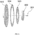
Figure 5 shows an assembly view of an alternative first embodiment in accordance with the disclosure; -
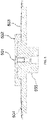
Figure 6 schematically illustrates a cross-section view of the alternative first embodiment in accordance with the disclosure; -
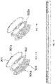
Figure 7 shows an assembly view of a second embodiment in accordance with the disclosure; -
Figure 8 shows a perspective view of a second embodiment in accordance with the disclosure; -
Figure 9 schematically illustrates a cross-section view of a second embodiment in accordance with the disclosure; -
Figure 10 schematically illustrates a cross-section view of a third embodiment in accordance with the disclosure; -
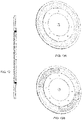
Figure 11A shows a first assembly view of a third embodiment in accordance with the disclosure; -
Figure 11B shows a second assembly view of a third embodiment in accordance with the disclosure; -
Figure 12 schematically illustrates a cross-section view of a fourth embodiment in accordance with the disclosure; and -
Figure 13A shows a first assembly view of a fourth embodiment in accordance with the disclosure. -
Figure 13B shows a second assembly view of a fourth embodiment in accordance with the disclosure. - Light converters convert exciting light in one wavelength range to another emission light in another wavelength range. For example, a light converter (which may comprise a phosphor wheel) may convert blue light to green/yellow light. To generate a desired colour sequence, the phosphor wheel may comprise colour segments with different conversion properties. To achieve the desired light output and alleviate localized heating of the conversion material in the laser spot area, fast rotation of the phosphor wheel is recommended.
- To increase the conversion light output, in many cases, phosphor wheels are designed to reflect light that is converted. With optical converters that comprise anti-reflection/high reflection (AR/HR) coating, metal disks with mirror coating are no longer required.
- Some performance characteristics such as conversion light output, colour, and lifetime are direct functions of working temperature. At higher operating temperatures, the conversion light output may decrease, the colour may shift, and the lifetime of phosphor wheel may be decreased. Under normal operating conditions, approximately 50%∼60% of the input power is output as heat, while the rest of the input power is converted to light. Particularly, when the input laser power reaches as high as several hundred watts, the heat generation during the conversion will cause high temperature more than 200 degrees Celsius (200°C). Thermal effect considerations must be therefore be taken into the product structure design. This is at least so that the solid optical converter can dissipate the heat by effective heat conduction. In order to increase the heat dissipation from the working optical converter, while also reducing weight loading of motor and decreasing the cost, a substrate to support or clamp optical converters may use metals with high thermal conductivity. Aluminium/aluminium alloy may be used as the substrate and manufactured in a cost efficient way of stamping or punching.
- An improved solution including a phosphor colour wheel can use ceramic phosphors as a converter. In some such devices, transparent silicone glue is applied to join the ceramic converter with a reflective metal disk.
Figure 2 is a schematic view of ceramic phosphor colour wheel of 200 of such a device. The colour segments are changed from the composition of phosphor-in-silicone-glue to the composition of ceramic phosphors. The phosphorceramic colour ring 201 or colour segments are attached to metal disk withmirror surface 202 by opticallytransparent silicone glue 203. The figure shows "exciting light" (input light) 204a e.g. from a laser-based illumination source or other light source (not shown) and emitting/converted reflected light 204b. However, because of the previously mentioned characteristics of the glue, the product cannot work under high temperature. Testing results show that the proper working temperature cannot be higher than 200 degrees Celsius (200°C). - Some devices disclosed herein provide a total solid product solution, avoiding any glue, adhesive or paste. As a result, the product therefore achieves an improved performance and improved durability, even in high power laser projection display systems. Devices disclosed herein may be used in applications where the solid state laser projector can be equipped with laser power in excess of than 100 watts. The working temperature of such devices can reach above 200 degrees Celsius (200°C) to enable high luminous brightness.
- Referring to
Figure 3 , there is shown an exploded perspective (assembly) view of such an optical converter colour wheel according to a first embodiment. A structure including a longitudinal member is provided to mechanically fasten the reflective ceramic phosphor colour wheel to the base. The solid optical converter (for example, a phosphor-ceramic based optical converter ring) 303 is secured between the base (or supporting substrate) 304 and the front plate (or cover hub) 302 by a central longitudinal member (for example a screw) 301. A threadedadapter 305 may then join the colour wheel with a motor. To precisely fix the optical converter, a step or a groove is formed on the supporting substrate. The cover hub only presses the optical converter along the inner rim. By such a configuration, a highly radical concentric structure is obtained. Any unbalance can be easily corrected by removing mass from the thicker circular column in the central portion of the cover hub (the hat body of the cover hub) in a subsequent dynamic balancing process. In this way, the material removing balancing process can be easily operated. In this example, the base andfront plate -
Figure 4 shows a sectional view of optical converter colour wheel according to the first embodiment ofFigure 3 . In this arrangement, the outerrim ring area 401 of thecover hub 302 may be as thin as 0.2mm. This advantageously allows the device to be used in light engine systems where the collecting lens system is close to the top surface of phosphor luminous ring. Additionally, jitter of the rotating colour wheel can be reduced in a dynamic balancing process. This is performed in order to avoid contact of the colour wheel with the lens system as a result of jitter. -
Figure 5 shows an assembly view of optical converter colour wheel according to an alternative first embodiment.Figure 6 shows a sectional view of the same structure. The cover hub in this example is formed by two parts: thehub 502 and theclamping ring 503, as shown inFigure 5 andFigure 6 . The solidoptical converter 504 is secured between a threadedbase substrate 505 and aclamp plate 503 by a centrallongitudinal member 501. In this way, the two parts of the cover hub (the hub and the clamping ring) can be manufactured separately by stamping/punching. As a result, a low cost alternative assembly is produced. -
Figure 7 shows an assembly view of an optical converter colour according to a second embodiment.Figure 8 shows a perspective view andFigure 9 shows a sectional view of the same structure. In this type structure, the phosphor-ceramic basedoptical converter ring 702 is seated on the outer ring shaped area of the base (or supporting substrate) 703. The optical member is clamped against thebase 703 by an S-shapedspring 701. The spring is mounted in the slot of thebase 703, with its onecircular end 701a pressing the inner rim of theoptical converter 702 and with its other claw shaped ends 701b holding against in the groove of thecentral shaft 703a of the supportingsubstrate 703. The depth and width of the slot, as well the groove height of the central shaft in the opticalconverter holder substrate 703 may preferably be designed and optimized so that the clamping force is appropriate. - Although an S-shaped spring is shown, other spring configurations are possible. There are 5 spring claws in the example embodiment shown in
Figure 5 . Alternatively, the number of claws may be different. The number of claws may be 6 or 8, for example. The material for this spring may be stainless steel, spring steel, brass, or copper. Other alternatives are also possible. - The spring can be manufactured as thin as 0.15mm in a cost effective method of stamping. By such a configuration, a highly concentric structure is provided. In such a structure, it is advantageously relatively easy to correct the unbalance by adding mass to the spring at some points. A cheap, simple and configurable assembly is therefore provided.
-
Figure 11A shows an assembly view of an optical converter colour wheel according to a third embodiment.Figure 10 shows a sectional view of the same structure. In this embodiment, the base (supporting substrate) 904, has projectingplugs 904a distributed along the outer flank. Thefitting cover ring 901 is made of spring material and hasrespective notches 901a in positions corresponding to the projecting plugs. The optical converter is held in place between the base and the cover ring by joining the cover ring to the base by the snap-on of plugs and notches. Theoptical converter 902 may be seated in a recess ring area of thecover ring 901. - One difference in this configuration is that the force is applied to the outer rim of the optical converter. In contrast, in other configurations (such as those described earlier), the clamping force is applied to the inner rim of the optical converter. By a configuration according to this third embodiment, as illustrated in
FIG. 11B ,individual colour segments 902a can be combined as required in order to generate a desired emission spectrum. They may then be fastened using a cover ring that engages with the outer edges of the segments, without the need for glue. Parts of the cover ring and base may be fabricated by stamping. Advantageously, this method is very cost effective. -
Figures 10 and 11A-B show projecting plugs on the base and respective notches on the cover ring, however, it will be apparent to the skilled person that alternatives are possible. For example, some or all of the plugs may be on the cover ring with corresponding notches in the base. -
Figure 12 shows a cross-sectional view of optical converter colour wheel andFigures 13A and 13B show two different perspective views, according to a fourth embodiment. In this embodiment, a cover plate is used to attach the optical converter colour wheel to the base, as an alternative to glue/adhesive. The optical converter is sandwiched between the base substrate and the cover plate. The base substrate and the cover plate can be made of metals, such as, aluminium alloy, stainless steel etc. The base substrate and the cover plate are mechanically attached by means of attaching the metals directly together. For example, the base substrate and the cover plate may be attached by welding (for example laser spot welding) or soldering. For the laser spot welding, only the laser spot area is affected by the heat. The expensive optical converter may therefore not be damaged by this method of fastening. - Although specific embodiments have been described, the skilled person will understand that variations and modifications are possible. For example, the designs may be applicable to all solid-state light converters and not necessarily only those using a ceramic material, for example a glass-based or plastics-based material may be used. The glass-based or plastics-based material may act as a substrate that is coated with a phosphor.
- For a reflective phosphor wheel, a layer of thin film coating of anti-reflection (AR) in the wavelength band of emission light, and/or another layer of thin film coating of high reflection (HR) in the wavelength band of emission light after conversion, may be applied to one or both sides of thin ceramic converters. This may be done in order to further improve the light conversion efficiency of ceramic converters. Testing results show that, with the AR/HR coating enhancement, the light conversion output will improved by around 10%. Moreover, AR/HR coating can work reliably under high temperature.
- Particularly, with HR coating on the ceramic converters, a high reflective metal disk may not be required. In known reflective phosphor wheel systems, a high reflective metal disk is provided. Such disks are typically composed of coated Silver/Sulphur layers on an aluminium substrate. With such a metal disk based phosphor wheel, after some period of operation, a failure mode of disk corrosion due to Silver oxidation and Sulphur migration among thin film layers may be observed.
- The solid optical converter colour wheel may include a colour wheel motor, an optical converter, a converter supporting substrate and a converter clamping component. The optical converter is secured directly by the supporting substrate and the clamping component. By such configurations eliminating or omitting glue/adhesive/paste, light converters can work properly under high temperature. For example, light converters disclosed herein can be used in high power laser projectors.
- These reflective phosphor wheels are used to convert exciting light in one wavelength range to another emission in the other wave length range. For example, the colour wheel may convert blue light to yellow or green light, particularly in laser projection display systems. These optical converters may also be used in automotive headlights.
- It will be appreciated that various of the above-disclosed and other features and functions, or alternatives thereof, may be desirably combined into many other different systems or applications. It will be further appreciated that various presently unforeseen or unanticipated alternatives, modifications, variations or improvements therein may be subsequently made by those skilled in the art which are also intended to be encompassed by the following claims.
Claims (21)
- A light converter comprising:a solid-state optical member configured to absorb light of an excitation wavelength and generate light of an emission wavelength, wherein the optical member is an annular optical member having a planar front and a rounded outer surface;a base, wherein a groove is formed on the base; anda mechanical fastener attaching the solid-state optical member to the base, the mechanical fastener applying force to an outer rim of the solid-state optical member;wherein the annular optical member is supported by the mechanical fastener and/or base along at least a part of the rounded outer surface of the annulus and/or at least part of the planar front of the optical member, andwherein no adhesive is used to attach the solid-state optical member to the base.
- The light converter of claim 1, wherein the mechanical fastener rigidly attaches the solid-state optical member to the base; orwherein the mechanical fastener removably attaches the solid state optical member to the base; orwherein the mechanical fastener comprises an elastic material.
- The light converter of claim 1, wherein the mechanical fastener comprises a longitudinal part that engages with a corresponding engaging point to allow coupling of the mechanical fastener to the base.
- The light converter of claim 3, wherein the mechanical fastener further comprises a front plate, the solid-state optical member being between the front plate and the base and the longitudinal part fixing the front plate to the engaging point, thereby to attach the solid-state optical member to the base; or
wherein the engaging point is in the base, or in a bracing component, distinct from the base. - The light converter of claim 1, wherein the base and/or mechanical fastener further comprise a plurality of projections, each engaging with a complementary anchor point on the mechanical fastener and/or base respectively.
- The light converter of claim 5, wherein each of the projections comprises a deformable clip.
- The light converter of claim 6, wherein the deformable clips are spring members, each exerting a force on their respective anchor point, thereby holding the mechanical fastener in place.
- The light converter of claim 5, wherein each of the projections comprises a projecting plug and each of the anchor points is a respective notch; or
wherein each of the complementary anchor points comprises one of: a ridge; a groove; or a lip. - The light converter of claim 1, wherein the mechanical fastener comprises a cover plate attached to the base and the solid-state optical member is between the cover plate and the base.
- The light converter of claim 9, wherein the cover plate is attached to the base by spot welding.
- The light converter of claim 1, wherein the solid-state optical member comprises one or more of: ceramic and glass; orwherein the solid-state optical member is configured to absorb blue light; orwherein the solid-state optical member is configured to generate yellow light or green light; or wherein the light converter is further configured to define an air gap between the base and the solid-state optical member.
- The light converter of claim 1, further comprising:an anti-reflection coating; and/ora high-reflection coating;wherein the anti-reflection coating or the high-reflection coating is disposed on one or both sides of the solid-state optical member.
- The light converter of claim 12, wherein the anti-reflection coating and/or the high-reflection coating are thin film coatings.
- A phosphor wheel comprising:the light converter of claim 1; anda motor arranged to rotate the base around an axis passing through the base and normal to a planar surface of the solid-state optical member.
- A light engine comprising:a light source; anda light converter according to claim 1 wherein the light source is arranged to apply exciting light to the light converter.
- The light engine of claim 15, wherein the light source is a laser-based illumination source.
- The light engine of claim 15 further comprising:
a motor arranged to rotate the base around an axis passing through the base and normal to a planar surface of the solid-state optical member. - A projector comprising the light engine of claim 17.
- An automotive headlight comprising the light engine of claim 15.
- A method of manufacturing a light converter, comprising:attaching a solid-state optical member to a base using a mechanical fastener,wherein the solid-state optical member is configured to absorb light of an excitation wavelength and generate light of an emission wavelength;the optical member being an annular optical member having a planar front and a rounded outer surface;a groove being formed on the base;wherein the annular optical member is supported by the mechanical fastener and/or base along at least a part of the rounded outer surface of the annulus and/or at least part of the planar front of the optical member, the mechanical fastener applying force to an inner rim of the solid-state optical member; andwherein no adhesive is used to attach the solid-state optical member to the base.
- The method of claim 20, wherein the mechanical fastener comprises a cover plate and attaching the solid-state optical member to the base comprises spot-welding the cover plate to the base; or
further comprising adding and/or removing mass to/from the mechanical fastener and/or base at a plurality of points, in order to balance the light converter.
Applications Claiming Priority (3)
| Application Number | Priority Date | Filing Date | Title |
|---|---|---|---|
| US14/737,816 US10145541B2 (en) | 2015-06-12 | 2015-06-12 | Optical converter colour wheel |
| EP16734069.4A EP3308208A1 (en) | 2015-06-12 | 2016-06-01 | Optical converter colour wheel |
| PCT/US2016/035314 WO2016200661A1 (en) | 2015-06-12 | 2016-06-01 | Optical converter colour wheel |
Related Parent Applications (1)
| Application Number | Title | Priority Date | Filing Date |
|---|---|---|---|
| EP16734069.4A Division EP3308208A1 (en) | 2015-06-12 | 2016-06-01 | Optical converter colour wheel |
Publications (1)
| Publication Number | Publication Date |
|---|---|
| EP4033283A1 true EP4033283A1 (en) | 2022-07-27 |
Family
ID=56297082
Family Applications (2)
| Application Number | Title | Priority Date | Filing Date |
|---|---|---|---|
| EP22161063.7A Pending EP4033283A1 (en) | 2015-06-12 | 2016-06-01 | Optical converter colour wheel |
| EP16734069.4A Withdrawn EP3308208A1 (en) | 2015-06-12 | 2016-06-01 | Optical converter colour wheel |
Family Applications After (1)
| Application Number | Title | Priority Date | Filing Date |
|---|---|---|---|
| EP16734069.4A Withdrawn EP3308208A1 (en) | 2015-06-12 | 2016-06-01 | Optical converter colour wheel |
Country Status (7)
| Country | Link |
|---|---|
| US (2) | US10145541B2 (en) |
| EP (2) | EP4033283A1 (en) |
| JP (2) | JP6912390B2 (en) |
| KR (2) | KR20240023211A (en) |
| CN (1) | CN107850749B (en) |
| TW (1) | TWI639852B (en) |
| WO (1) | WO2016200661A1 (en) |
Families Citing this family (19)
| Publication number | Priority date | Publication date | Assignee | Title |
|---|---|---|---|---|
| US9733469B2 (en) * | 2015-07-01 | 2017-08-15 | Materion Corporation | Unbalanced hub design |
| CN108139520A (en) * | 2015-09-29 | 2018-06-08 | 松下知识产权经营株式会社 | Wavelength changing element and light-emitting device |
| US10802386B2 (en) * | 2015-12-15 | 2020-10-13 | Materion Corporation | Enhanced wavelength conversion device |
| JP2017151199A (en) * | 2016-02-23 | 2017-08-31 | セイコーエプソン株式会社 | Wavelength conversion device, illumination device, and projector |
| JP6658074B2 (en) * | 2016-02-24 | 2020-03-04 | セイコーエプソン株式会社 | Wavelength conversion element, light source device and projector |
| DE102016225361A1 (en) * | 2016-12-16 | 2018-06-21 | Osram Gmbh | LIGHTING DEVICE WITH FLUORESCENT WHEEL |
| CN108803213B (en) | 2017-04-27 | 2021-03-19 | 中强光电股份有限公司 | Wavelength conversion filter module and lighting system |
| EP3646114B1 (en) * | 2017-06-29 | 2023-06-28 | Materion Precision Optics (Shanghai) Limited | Phosphor wheel |
| WO2019056209A1 (en) * | 2017-09-20 | 2019-03-28 | Materion Precision Optics (Shanghai) Limited | Phosphor wheel with inorganic binder |
| CN109782429B (en) * | 2017-11-13 | 2021-10-26 | 中强光电股份有限公司 | Wavelength conversion device and projector |
| CN110716376B (en) * | 2018-07-13 | 2021-11-09 | 中强光电股份有限公司 | Wavelength conversion element, projection device and manufacturing method of wavelength conversion element |
| JP7259357B2 (en) * | 2019-01-29 | 2023-04-18 | セイコーエプソン株式会社 | Wavelength conversion element, illumination device and projector |
| JP6922939B2 (en) * | 2019-03-18 | 2021-08-18 | セイコーエプソン株式会社 | Wavelength conversion element, light source device, projector, and manufacturing method of wavelength conversion element |
| CN116774424A (en) * | 2020-04-08 | 2023-09-19 | 台达电子工业股份有限公司 | Wavelength conversion element |
| CN212302196U (en) | 2020-07-16 | 2021-01-05 | 中强光电股份有限公司 | Wavelength conversion module and projector |
| CN114488673B (en) | 2020-10-27 | 2023-08-08 | 中强光电股份有限公司 | wavelength conversion element |
| CN213276238U (en) * | 2020-11-23 | 2021-05-25 | 中强光电股份有限公司 | Color Wheel Module and Projector |
| JP2022185236A (en) * | 2021-06-02 | 2022-12-14 | セイコーエプソン株式会社 | Wavelength conversion device, light source device and projector |
| WO2023120756A1 (en) * | 2021-12-21 | 2023-06-29 | 엘지전자 주식회사 | Phosphor wheel and image projection device comprising same |
Citations (5)
| Publication number | Priority date | Publication date | Assignee | Title |
|---|---|---|---|---|
| US20050168709A1 (en) * | 2004-01-30 | 2005-08-04 | Asia Optical Co., Inc. | Color wheel |
| EP2113714A1 (en) * | 2008-04-30 | 2009-11-04 | Martin Professional A/S | Color wheel |
| WO2014016574A1 (en) | 2012-07-23 | 2014-01-30 | Eis Optics Limited | Compact light engine |
| US20140254133A1 (en) * | 2011-10-21 | 2014-09-11 | Osram Gmbh | Phosphor wheel, method for producing a phosphor wheel and lighting arrangement |
| WO2015068562A1 (en) * | 2013-11-08 | 2015-05-14 | 日本電気硝子株式会社 | Fluorescent wheel for projectors and light emitting device for projectors |
Family Cites Families (12)
| Publication number | Priority date | Publication date | Assignee | Title |
|---|---|---|---|---|
| DE102005029296B4 (en) * | 2005-06-22 | 2019-09-19 | Oerlikon Surface Solutions Ag, Pfäffikon | Color wheel with self-aligned segments |
| JP5190370B2 (en) * | 2005-11-04 | 2013-04-24 | エリコン・トレーディング・アクチェンゲゼルシャフト,トリュープバッハ | Color wheel with balancing means |
| US7839587B2 (en) * | 2006-08-24 | 2010-11-23 | Oerlikon Trading Ag, Trubbach | Color wheel |
| TW200834220A (en) * | 2007-02-12 | 2008-08-16 | Young Optics Inc | Color wheel |
| US7942535B2 (en) * | 2008-04-30 | 2011-05-17 | Martin Professional A/S | Color wheel |
| US8684560B2 (en) * | 2009-11-18 | 2014-04-01 | Stanley Electric Co., Ltd. | Semiconductor light source apparatus and lighting unit |
| US8556437B2 (en) * | 2009-12-17 | 2013-10-15 | Stanley Electric Co., Ltd. | Semiconductor light source apparatus and lighting unit |
| CN202040748U (en) * | 2011-03-08 | 2011-11-16 | 绎立锐光科技开发(深圳)有限公司 | Optical Wavelength Conversion Wheel Assembly |
| JP5673247B2 (en) * | 2011-03-15 | 2015-02-18 | セイコーエプソン株式会社 | Light source device and projector |
| JP2012243701A (en) * | 2011-05-24 | 2012-12-10 | Stanley Electric Co Ltd | Light source device and lighting system |
| DE102012211837A1 (en) * | 2012-07-06 | 2014-01-09 | Osram Gmbh | Illuminating device with luminous arrangement and laser |
| CN104566229B (en) * | 2013-10-15 | 2016-06-08 | 深圳市光峰光电技术有限公司 | Manufacturing method of wavelength conversion device |
-
2015
- 2015-06-12 US US14/737,816 patent/US10145541B2/en active Active
-
2016
- 2016-06-01 KR KR1020247004681A patent/KR20240023211A/en not_active Withdrawn
- 2016-06-01 JP JP2017563287A patent/JP6912390B2/en active Active
- 2016-06-01 EP EP22161063.7A patent/EP4033283A1/en active Pending
- 2016-06-01 WO PCT/US2016/035314 patent/WO2016200661A1/en not_active Ceased
- 2016-06-01 EP EP16734069.4A patent/EP3308208A1/en not_active Withdrawn
- 2016-06-01 KR KR1020187000185A patent/KR20180017075A/en not_active Ceased
- 2016-06-01 CN CN201680033331.2A patent/CN107850749B/en active Active
- 2016-06-13 TW TW105118309A patent/TWI639852B/en active
-
2018
- 2018-10-29 US US16/173,022 patent/US10473299B2/en active Active
-
2020
- 2020-07-28 JP JP2020127149A patent/JP6934094B2/en active Active
Patent Citations (6)
| Publication number | Priority date | Publication date | Assignee | Title |
|---|---|---|---|---|
| US20050168709A1 (en) * | 2004-01-30 | 2005-08-04 | Asia Optical Co., Inc. | Color wheel |
| EP2113714A1 (en) * | 2008-04-30 | 2009-11-04 | Martin Professional A/S | Color wheel |
| US20140254133A1 (en) * | 2011-10-21 | 2014-09-11 | Osram Gmbh | Phosphor wheel, method for producing a phosphor wheel and lighting arrangement |
| WO2014016574A1 (en) | 2012-07-23 | 2014-01-30 | Eis Optics Limited | Compact light engine |
| WO2015068562A1 (en) * | 2013-11-08 | 2015-05-14 | 日本電気硝子株式会社 | Fluorescent wheel for projectors and light emitting device for projectors |
| US20160238922A1 (en) * | 2013-11-08 | 2016-08-18 | Nippon Electric Glass Co., Ltd. | Fluorescent wheel for projectors and light emitting device for projectors |
Also Published As
| Publication number | Publication date |
|---|---|
| JP2020173484A (en) | 2020-10-22 |
| US10473299B2 (en) | 2019-11-12 |
| JP6912390B2 (en) | 2021-08-04 |
| JP6934094B2 (en) | 2021-09-08 |
| CN107850749A (en) | 2018-03-27 |
| WO2016200661A1 (en) | 2016-12-15 |
| KR20180017075A (en) | 2018-02-20 |
| US20160363294A1 (en) | 2016-12-15 |
| TW201702689A (en) | 2017-01-16 |
| CN107850749B (en) | 2021-04-06 |
| US20190170331A1 (en) | 2019-06-06 |
| US10145541B2 (en) | 2018-12-04 |
| TWI639852B (en) | 2018-11-01 |
| KR20240023211A (en) | 2024-02-20 |
| JP2018520477A (en) | 2018-07-26 |
| EP3308208A1 (en) | 2018-04-18 |
Similar Documents
| Publication | Publication Date | Title |
|---|---|---|
| US10473299B2 (en) | Optical converter colour wheel | |
| JP7170073B2 (en) | High optical power light conversion device using phosphor elements with solder attachment | |
| CN104865779B (en) | Cooling of converter devices for high brightness light sources | |
| JP2013528902A (en) | Mounting tool for LED-based lighting module to fixed member | |
| CN207232511U (en) | Combination wheels and devices including combination wheels | |
| US10865950B2 (en) | Light source unit and projection-type display | |
| CN206819041U (en) | Color wheel module, light source module and projection system | |
| CN109804196B (en) | Light conversion device with clamped light converter | |
| KR102488528B1 (en) | Phosphor wheel with inorganic binder | |
| JP2022145953A (en) | Enhanced wavelength conversion device | |
| US20140168616A1 (en) | Light source apparatus and projection type display apparatus | |
| CN109654391B (en) | wavelength conversion device | |
| CN210401993U (en) | A fluorescent wheel assembly | |
| CN110837198A (en) | Wavelength conversion components and laser light sources | |
| JP2017151350A (en) | Wavelength conversion device, method for manufacturing wavelength conversion device, illumination device, and projector | |
| JP2022069537A (en) | Optical conversion device with improved inorganic binder | |
| US20190339604A1 (en) | Optical unit, light source apparatus, and projection type display apparatus | |
| CN220793070U (en) | Light source device |
Legal Events
| Date | Code | Title | Description |
|---|---|---|---|
| PUAI | Public reference made under article 153(3) epc to a published international application that has entered the european phase |
Free format text: ORIGINAL CODE: 0009012 |
|
| STAA | Information on the status of an ep patent application or granted ep patent |
Free format text: STATUS: THE APPLICATION HAS BEEN PUBLISHED |
|
| AC | Divisional application: reference to earlier application |
Ref document number: 3308208 Country of ref document: EP Kind code of ref document: P |
|
| AK | Designated contracting states |
Kind code of ref document: A1 Designated state(s): AL AT BE BG CH CY CZ DE DK EE ES FI FR GB GR HR HU IE IS IT LI LT LU LV MC MK MT NL NO PL PT RO RS SE SI SK SM TR |
|
| STAA | Information on the status of an ep patent application or granted ep patent |
Free format text: STATUS: REQUEST FOR EXAMINATION WAS MADE |
|
| 17P | Request for examination filed |
Effective date: 20230112 |
|
| RBV | Designated contracting states (corrected) |
Designated state(s): AL AT BE BG CH CY CZ DE DK EE ES FI FR GB GR HR HU IE IS IT LI LT LU LV MC MK MT NL NO PL PT RO RS SE SI SK SM TR |
|
| P01 | Opt-out of the competence of the unified patent court (upc) registered |
Effective date: 20230530 |
|
| STAA | Information on the status of an ep patent application or granted ep patent |
Free format text: STATUS: EXAMINATION IS IN PROGRESS |
|
| 17Q | First examination report despatched |
Effective date: 20240605 |
|
| STAA | Information on the status of an ep patent application or granted ep patent |
Free format text: STATUS: THE APPLICATION IS DEEMED TO BE WITHDRAWN |