EP4033280B1 - Spectral processing apparatus and reconfigurable optical add-drop multiplexer - Google Patents
Spectral processing apparatus and reconfigurable optical add-drop multiplexer Download PDFInfo
- Publication number
- EP4033280B1 EP4033280B1 EP20865440.0A EP20865440A EP4033280B1 EP 4033280 B1 EP4033280 B1 EP 4033280B1 EP 20865440 A EP20865440 A EP 20865440A EP 4033280 B1 EP4033280 B1 EP 4033280B1
- Authority
- EP
- European Patent Office
- Prior art keywords
- assembly
- light beam
- lens
- port
- sub
- Prior art date
- Legal status (The legal status is an assumption and is not a legal conclusion. Google has not performed a legal analysis and makes no representation as to the accuracy of the status listed.)
- Active
Links
Images





Classifications
-
- G—PHYSICS
- G02—OPTICS
- G02B—OPTICAL ELEMENTS, SYSTEMS OR APPARATUS
- G02B6/00—Light guides; Structural details of arrangements comprising light guides and other optical elements, e.g. couplings
- G02B6/24—Coupling light guides
- G02B6/26—Optical coupling means
- G02B6/28—Optical coupling means having data bus means, i.e. plural waveguides interconnected and providing an inherently bidirectional system by mixing and splitting signals
- G02B6/293—Optical coupling means having data bus means, i.e. plural waveguides interconnected and providing an inherently bidirectional system by mixing and splitting signals with wavelength selective means
- G02B6/29304—Optical coupling means having data bus means, i.e. plural waveguides interconnected and providing an inherently bidirectional system by mixing and splitting signals with wavelength selective means operating by diffraction, e.g. grating
- G02B6/29305—Optical coupling means having data bus means, i.e. plural waveguides interconnected and providing an inherently bidirectional system by mixing and splitting signals with wavelength selective means operating by diffraction, e.g. grating as bulk element, i.e. free space arrangement external to a light guide
-
- G—PHYSICS
- G02—OPTICS
- G02B—OPTICAL ELEMENTS, SYSTEMS OR APPARATUS
- G02B15/00—Optical objectives with means for varying the magnification
- G02B15/14—Optical objectives with means for varying the magnification by axial movement of one or more lenses or groups of lenses relative to the image plane for continuously varying the equivalent focal length of the objective
-
- G—PHYSICS
- G02—OPTICS
- G02B—OPTICAL ELEMENTS, SYSTEMS OR APPARATUS
- G02B27/00—Optical systems or apparatus not provided for by any of the groups G02B1/00 - G02B26/00, G02B30/00
- G02B27/09—Beam shaping, e.g. changing the cross-sectional area, not otherwise provided for
- G02B27/0938—Using specific optical elements
- G02B27/095—Refractive optical elements
- G02B27/0955—Lenses
-
- G—PHYSICS
- G02—OPTICS
- G02B—OPTICAL ELEMENTS, SYSTEMS OR APPARATUS
- G02B27/00—Optical systems or apparatus not provided for by any of the groups G02B1/00 - G02B26/00, G02B30/00
- G02B27/09—Beam shaping, e.g. changing the cross-sectional area, not otherwise provided for
- G02B27/0938—Using specific optical elements
- G02B27/0977—Reflective elements
-
- G—PHYSICS
- G02—OPTICS
- G02B—OPTICAL ELEMENTS, SYSTEMS OR APPARATUS
- G02B27/00—Optical systems or apparatus not provided for by any of the groups G02B1/00 - G02B26/00, G02B30/00
- G02B27/28—Optical systems or apparatus not provided for by any of the groups G02B1/00 - G02B26/00, G02B30/00 for polarising
-
- G—PHYSICS
- G02—OPTICS
- G02B—OPTICAL ELEMENTS, SYSTEMS OR APPARATUS
- G02B6/00—Light guides; Structural details of arrangements comprising light guides and other optical elements, e.g. couplings
- G02B6/24—Coupling light guides
- G02B6/26—Optical coupling means
- G02B6/27—Optical coupling means with polarisation selective and adjusting means
- G02B6/2706—Optical coupling means with polarisation selective and adjusting means as bulk elements, i.e. free space arrangements external to a light guide, e.g. polarising beam splitters
-
- G—PHYSICS
- G02—OPTICS
- G02B—OPTICAL ELEMENTS, SYSTEMS OR APPARATUS
- G02B6/00—Light guides; Structural details of arrangements comprising light guides and other optical elements, e.g. couplings
- G02B6/24—Coupling light guides
- G02B6/26—Optical coupling means
- G02B6/28—Optical coupling means having data bus means, i.e. plural waveguides interconnected and providing an inherently bidirectional system by mixing and splitting signals
- G02B6/293—Optical coupling means having data bus means, i.e. plural waveguides interconnected and providing an inherently bidirectional system by mixing and splitting signals with wavelength selective means
- G02B6/29304—Optical coupling means having data bus means, i.e. plural waveguides interconnected and providing an inherently bidirectional system by mixing and splitting signals with wavelength selective means operating by diffraction, e.g. grating
- G02B6/29305—Optical coupling means having data bus means, i.e. plural waveguides interconnected and providing an inherently bidirectional system by mixing and splitting signals with wavelength selective means operating by diffraction, e.g. grating as bulk element, i.e. free space arrangement external to a light guide
- G02B6/29313—Optical coupling means having data bus means, i.e. plural waveguides interconnected and providing an inherently bidirectional system by mixing and splitting signals with wavelength selective means operating by diffraction, e.g. grating as bulk element, i.e. free space arrangement external to a light guide characterised by means for controlling the position or direction of light incident to or leaving the diffractive element, e.g. for varying the wavelength response
-
- G—PHYSICS
- G02—OPTICS
- G02B—OPTICAL ELEMENTS, SYSTEMS OR APPARATUS
- G02B6/00—Light guides; Structural details of arrangements comprising light guides and other optical elements, e.g. couplings
- G02B6/24—Coupling light guides
- G02B6/26—Optical coupling means
- G02B6/28—Optical coupling means having data bus means, i.e. plural waveguides interconnected and providing an inherently bidirectional system by mixing and splitting signals
- G02B6/293—Optical coupling means having data bus means, i.e. plural waveguides interconnected and providing an inherently bidirectional system by mixing and splitting signals with wavelength selective means
- G02B6/29379—Optical coupling means having data bus means, i.e. plural waveguides interconnected and providing an inherently bidirectional system by mixing and splitting signals with wavelength selective means characterised by the function or use of the complete device
- G02B6/2938—Optical coupling means having data bus means, i.e. plural waveguides interconnected and providing an inherently bidirectional system by mixing and splitting signals with wavelength selective means characterised by the function or use of the complete device for multiplexing or demultiplexing, i.e. combining or separating wavelengths, e.g. 1xN, NxM
- G02B6/29382—Optical coupling means having data bus means, i.e. plural waveguides interconnected and providing an inherently bidirectional system by mixing and splitting signals with wavelength selective means characterised by the function or use of the complete device for multiplexing or demultiplexing, i.e. combining or separating wavelengths, e.g. 1xN, NxM including at least adding or dropping a signal, i.e. passing the majority of signals
-
- G—PHYSICS
- G02—OPTICS
- G02B—OPTICAL ELEMENTS, SYSTEMS OR APPARATUS
- G02B6/00—Light guides; Structural details of arrangements comprising light guides and other optical elements, e.g. couplings
- G02B6/24—Coupling light guides
- G02B6/26—Optical coupling means
- G02B6/28—Optical coupling means having data bus means, i.e. plural waveguides interconnected and providing an inherently bidirectional system by mixing and splitting signals
- G02B6/293—Optical coupling means having data bus means, i.e. plural waveguides interconnected and providing an inherently bidirectional system by mixing and splitting signals with wavelength selective means
- G02B6/29379—Optical coupling means having data bus means, i.e. plural waveguides interconnected and providing an inherently bidirectional system by mixing and splitting signals with wavelength selective means characterised by the function or use of the complete device
- G02B6/29395—Optical coupling means having data bus means, i.e. plural waveguides interconnected and providing an inherently bidirectional system by mixing and splitting signals with wavelength selective means characterised by the function or use of the complete device configurable, e.g. tunable or reconfigurable
-
- G—PHYSICS
- G02—OPTICS
- G02B—OPTICAL ELEMENTS, SYSTEMS OR APPARATUS
- G02B6/00—Light guides; Structural details of arrangements comprising light guides and other optical elements, e.g. couplings
- G02B6/24—Coupling light guides
- G02B6/26—Optical coupling means
- G02B6/28—Optical coupling means having data bus means, i.e. plural waveguides interconnected and providing an inherently bidirectional system by mixing and splitting signals
- G02B6/293—Optical coupling means having data bus means, i.e. plural waveguides interconnected and providing an inherently bidirectional system by mixing and splitting signals with wavelength selective means
- G02B6/29379—Optical coupling means having data bus means, i.e. plural waveguides interconnected and providing an inherently bidirectional system by mixing and splitting signals with wavelength selective means characterised by the function or use of the complete device
- G02B6/2938—Optical coupling means having data bus means, i.e. plural waveguides interconnected and providing an inherently bidirectional system by mixing and splitting signals with wavelength selective means characterised by the function or use of the complete device for multiplexing or demultiplexing, i.e. combining or separating wavelengths, e.g. 1xN, NxM
Definitions
- This application relates to the field of optical communications, and in particular, to a spectrum processing apparatus and a reconfigurable optical add-drop multiplexer.
- spectrum processing apparatuses having a spectrum processing capability can flexibly change spectral characteristics or can be used to detect a spectrum based on requirements of optical networks.
- the spectrum processing apparatuses are important components for high-performance intelligent optical networks.
- a spectrum processing apparatus used for wavelength blocking is used as an example.
- a dispersive assembly separates wavelengths of an incident light beam, and light beams with different wavelengths are incident onto different positions of a spatial light modulator (spatial light modulator, SLM).
- SLM spatial light modulator
- the spectrum processing apparatus used for wavelength blocking requires bandwidth in each wavelength channel to be as large as possible, and then a light spot formed on the SLM needs to be as small as possible.
- a light spot formed on the SLM needs to be as small as possible.
- small light spots on the SLM may produce glitches in the spectrum, which makes it difficult to form a smooth spectrum.
- the spectrum processing apparatus used for wavelength blocking is not suitable for overall spectrum adjustment. Therefore, a current spectrum processing apparatus has a limited function.
- US 2006/0067611 A1 describes an optical coupling device including: at least a first input port for delivering an optical input signal beam that includes a plurality of wavelength channels; at least a first optical output port for receiving an optical output signal beam; a wavelength dispersion element for spatially separating the plurality of wavelength channels in the optical input signal beam to form a plurality of spatially separated wavelength channel beams; an optical coupling device for independently modifying the phase of each of the spatially separated wavelength channel beams such that, for at least one wavelength channel beam, a selected fraction of the light is coupled to the first output port and a fraction of the light is coupled away from the first output port.
- the invention provides a spectrum processing apparatus and a reconfigurable optical add-drop multiplexer, thereby enriching functions of the spectrum processing apparatus according to the appended claims.
- an embodiment of this application provides a spectrum processing apparatus, including: a port assembly, a lens assembly, a dispersive assembly, a spatial light modulator SLM, and a reflective element, where the port assembly includes N ports, and the lens assembly includes M lenses, where N is an integer greater than 1, and M is an integer greater than or equal to 1 and less than or equal to N.
- Each port in the port assembly is configured to transmit an input first light beam to a lens corresponding to the port.
- Each lens in the lens assembly is configured to adjust a width of the first light beam to obtain a second light beam, and transmit the second light beam to the reflective element.
- the reflective element is configured to reflect the second light beam to the dispersive assembly.
- the dispersive assembly is configured to decompose the second light beam into a plurality of sub-wavelength light beams, and transmit the plurality of sub-wavelength light beams to the reflective element.
- the reflective element is further configured to reflect the plurality of sub-wavelength light beams to the SLM.
- the SLM is configured to modulate the plurality of sub-wavelength light beams, and reflect at least one modulated sub-wavelength light beam to the reflective element.
- the reflective element is further configured to reflect the at least one sub-wavelength light beam to the dispersive assembly.
- the dispersive assembly is further configured to multiplex the at least one sub-wavelength light beam, and transmit a multiplexed light beam successively through the reflective element and the lens assembly to the port assembly.
- the SLM may be a liquid crystal modulator, a liquid crystal on silicon (Liquid Crystal on Silicon, LCoS) array, a microelectromechanical system (Microelectromechanical Systems, MEMS) micromirror array, or the like.
- the SLM changes a reflection direction of the sub-wavelength light beam such that the sub-wavelength light beam can be completely reflected to a port without any loss, or the sub-wavelength light beam cannot be reflected to the port, or a part of the sub-wavelength light beam can be reflected to the port.
- the port assembly includes at least two ports, and each lens in the lens assembly can adjust a width of a light beam from a port.
- a width of a light beam after passing through a lens may become larger or smaller, or may remain unchanged, and sizes of light spots formed by light beams of different widths on the SLM are also different. Therefore, the plurality of ports of the spectrum processing apparatus may be used to implement different functions, thereby enriching functions of the spectrum processing apparatus.
- a focal length of each lens of the M lenses is adjustable.
- the M lenses are all zoom lenses, for example, variable-focus liquid lenses.
- a focal length of each lens may be adjusted at any time, and a width of a first light beam passing through a same lens may also be adjusted at any time, so that each port can adapt to a plurality of functions.
- each port includes an input port and an output port; and each port in the port assembly being configured to transmit an input first light beam to a lens corresponding to the port includes:
- each port may include an input port and an output port, and then an input light beam and an output light beam are separated on a transmission path, thereby improving applicability of this solution.
- the spectrum processing apparatus further includes a polarization assembly, and the polarization assembly is located between the lens assembly and the reflective element; and the polarization assembly is configured to separate polarizations of the second light beam into a first polarized light beam and a second polarized light beam, and transmit the first polarized light beam and the second polarized light beam to the dispersive assembly, where the first polarized light beam and the second polarized light beam have mutually orthogonal polarization components.
- the spectrum processing apparatus may further be provided with the polarization assembly, thereby improving scalability of this solution.
- the N ports are symmetrically distributed with respect to an optic axis of the reflective element.
- applicable functions of the spectrum proce ssing apparatus not only have different requirements for sizes of light spots formed on the SLM, but also have different requirements for insertion loss (Insertion Loss, IL) of each port.
- IL insertion loss
- a shorter distance between a port and the optic axis of the reflective element indicates smaller insertion loss of the port. Therefore, in design of distribution of ports, the ports may be symmetrically distributed with respect to the optic axis of the reflective element, so as to differentiate insertion loss of the ports during use, and select corresponding ports to implement different functions.
- an embodiment of this application provides another spectrum processing apparatus, including: a port assembly, a lens assembly, a dispersive assembly, a spatial light modulator SLM, and a first lens, where the port assembly includes N ports, and the lens assembly includes M lenses, where N is an integer greater than 1, and M is an integer greater than or equal to 1 and less than or equal to N.
- Each port in the port assembly is configured to transmit an input first light beam to a lens corresponding to the port.
- Each lens in the lens assembly is configured to adjust a width of the first light beam to obtain a second light beam, and transmit the second light beam to the dispersive assembly.
- the dispersive assembly is configured to decompose the second light beam into a plurality of sub-wavelength light beams in a first plane, and transmit the plurality of sub-wavelength light beams to the first lens.
- the first lens is configured to refract the plurality of sub-wavelength light beams to the SLM in the first plane, and transmit the plurality of sub-wavelength light beams to the SLM in a second plane, where the second plane is perpendicular to the first plane.
- the SLM is configured to modulate the plurality of sub-wavelength light beams, and reflect at least one modulated sub-wavelength light beam to the first lens.
- the first lens is further configured to refract the at least one sub-wavelength light beam to the dispersive assembly in the first plane, and transmit the at least one sub-wavelength light beam to the dispersive assembly in the second plane.
- the dispersive assembly is further configured to multiplex the at least one sub-wavelength light beam, and transmit a multiplexed light beam through the lens assembly to the port assembly.
- a focal length of each lens of the M lenses is adjustable.
- the M lenses are all zoom lenses.
- each port includes an input port and an output port; and each port in the port assembly being configured to transmit an input first light beam to a lens corresponding to the port includes:
- the spectrum processing apparatus further includes a polarization assembly, and the polarization assembly is located between the lens assembly and the dispersive assembly; and the polarization assembly is configured to separate polarizations of the second light beam into a first polarized light beam and a second polarized light beam, and transmit the first polarized light beam and the second polarized light beam to the dispersive assembly, where the first polarized light beam and the second polarized light beam have mutually orthogonal polarization components.
- the N ports are symmetrically distributed with respect to an optic axis of the first lens.
- an embodiment of this application provides another spectrum processing apparatus, including: a port assembly, a lens assembly, a dispersive assembly, a spatial light modulator SLM, a first lens, and a second lens, where the port assembly includes N ports, and the lens assembly includes M lenses, where N is an integer greater than 1, and M is an integer greater than or equal to 1 and less than or equal to N.
- Each port in the port assembly is configured to transmit an input first light beam to a lens corresponding to the port.
- Each lens in the lens assembly is configured to adjust a width of the first light beam to obtain a second light beam, and transmit the second light beam to the second lens.
- the second lens is configured to refract the second light beam to the dispersive assembly in a second plane.
- the dispersive assembly is configured to decompose the second light beam into a plurality of sub-wavelength light beams in a first plane, and transmit the plurality of sub-wavelength light beams to the first lens, where the first plane is perpendicular to the second plane.
- the first lens is configured to refract the plurality of sub-wavelength light beams to the SLM in the first plane and the second plane.
- the SLM is configured to modulate the plurality of sub-wavelength light beams, and reflect at least one modulated sub-wavelength light beam to the first lens.
- the first lens is further configured to refract the at least one sub-wavelength light beam to the dispersive assembly in the first plane and the second plane.
- the dispersive assembly is further configured to multiplex the at least one sub-wavelength light beam, and transmit a multiplexed light beam successively through the second lens and the lens assembly to the port assembly.
- a focal length of each lens of the M lenses is adjustable.
- the second lens is located between the dispersive assembly and the lens assembly
- the first lens is located between the dispersive assembly and the SLM
- a distance between the first lens and the dispersive assembly is equal to a focal length of the first lens
- a distance between the second lens and the dispersive assembly is equal to a focal length of the second lens
- a distance between the first lens and the SLM is equal to the focal length of the first lens
- the first lens and the second lens use a standard 4f optical lens configuration, and a transmission path of a light beam is more regular, thereby improving implementability of this solution.
- the M lenses are all zoom lenses.
- each port includes an input port and an output port; and each port in the port assembly being configured to transmit an input first light beam to a lens corresponding to the port includes:
- the spectrum processing apparatus further includes a polarization assembly, and the polarization assembly is located between the lens assembly and the second lens; and the polarization assembly is configured to separate polarizations of the second light beam into a first polarized light beam and a second polarized light beam, and transmit the first polarized light beam and the second polarized light beam to the first lens, where the first polarized light beam and the second polarized light beam have mutually orthogonal polarization components.
- the N ports are symmetrically distributed with respect to an optic axis of the first lens or the second lens.
- an embodiment of this application provides a reconfigurable optical add-drop multiplexer (Reconfigurable Optical Add-Drop Multiplexer, ROADM), including: an add module, a drop module, and the spectrum processing apparatus according to any one of the first aspect to the third aspect.
- the spectrum processing apparatus is configured to implement a spectrum processing function.
- the add module is configured to add a local optical wavelength signal from the port assembly of the spectrum processing apparatus.
- the drop module is configured to drop a local optical wavelength signal from the port assembly of the spectrum processing apparatus.
- an embodiment of this application provides a spectrum processing method, applied to a spectrum processing apparatus, where the spectrum processing apparatus includes: a port assembly, a lens assembly, a dispersive assembly, a spatial light modulator SLM, and a reflective element, where the port assembly includes N ports, and the lens assembly includes M lenses, where N is an integer greater than 1, and M is an integer greater than or equal to 1 and less than or equal to N.
- the method includes: transmitting, by each port in the port assembly, an input first light beam to a lens corresponding to each port; adjusting, by each lens in the lens assembly, a width of the first light beam to obtain a second light beam, and transmitting the second light beam to the reflective element; reflecting, by the reflective element, the second light beam to the dispersive assembly; decomposing, by the dispersive assembly, the second light beam into a plurality of sub-wavelength light beams, and transmitting the plurality of sub-wavelength light beams to the reflective element; reflecting, by the reflective element, the plurality of sub-wavelength light beams to the SLM; modulating, by the SLM, the plurality of sub-wavelength light beams, and reflecting at least one modulated sub-wavelength light beam to the reflective element; reflecting, by the reflective element, the at least one sub-wavelength light beam to the dispersive assembly; and multiplexing, by the dispersive assembly, the at least one sub-wavelength light beam, and transmitting a multiplexed light beam successive
- the M lenses are all zoom lenses.
- each port includes an input port and an output port; and the transmitting, by each port in the port assembly, an input first light beam to a lens corresponding to each port includes:
- the spectrum processing apparatus further includes a polarization assembly, and the polarization assembly is located between the lens assembly and the reflective element; and the method further includes:
- the N ports are symmetrically distributed with respect to an optic axis of the reflective element.
- an embodiment of this application provides another spectrum processing method, applied to a spectrum processing apparatus, where the spectrum processing apparatus includes: a port assembly, a lens assembly, a dispersive assembly, a spatial light modulator SLM, and a first lens, where the port assembly includes N ports, and the lens assembly includes M lenses, where N is an integer greater than 1, and M is an integer greater than or equal to 1 and less than or equal to N.
- the method includes: transmitting, by each port in the port assembly, an input first light beam to a lens corresponding to each port; adjusting, by each lens in the lens assembly, a width of the first light beam to obtain a second light beam, and transmitting the second light beam to the dispersive assembly; decomposing, by the dispersive assembly, the second light beam into a plurality of sub-wavelength light beams in a first plane, and transmitting the plurality of sub-wavelength light beams to the first lens; refracting, by the first lens, the plurality of sub-wavelength light beams to the SLM in the first plane, and transmitting the plurality of sub-wavelength light beams to the SLM in a second plane, where the second plane is perpendicular to the first plane; modulating, by the SLM, the plurality of sub-wavelength light beams, and reflecting at least one modulated sub-wavelength light beam to the first lens; refracting, by the first lens, the at least one sub-wavelength light beam to the dispersive
- the M lenses are all zoom lenses.
- each port includes an input port and an output port; and the transmitting, by each port in the port assembly, an input first light beam to a lens corresponding to each port includes:
- the spectrum processing apparatus further includes a polarization assembly, and the polarization assembly is located between the lens assembly and the dispersive assembly; and the method further includes: separating, by the polarization assembly, polarizations of the second light beam into a first polarized light beam and a second polarized light beam, and transmitting the first polarized light beam and the second polarized light beam to the dispersive assembly, where the first polarized light beam and the second polarized light beam have mutually orthogonal polarization components.
- the N ports are symmetrically distributed with respect to an optic axis of the first lens.
- an embodiment of this application provides another spectrum processing method, applied to a spectrum processing apparatus, where the spectrum processing apparatus includes: a port assembly, a lens assembly, a dispersive assembly, a spatial light modulator SLM, a first lens, and a second lens, where the port assembly includes N ports, and the lens assembly includes M lenses, where N is an integer greater than 1, and M is an integer greater than or equal to 1 and less than or equal to N.
- the method includes: transmitting, by each port in the port assembly, an input first light beam to a lens corresponding to each port; adjusting, by each lens in the lens assembly, a width of the first light beam to obtain a second light beam, and transmitting the second light beam to the second lens; refracting, by the second lens, the second light beam to the dispersive assembly in a second plane; decomposing, by the dispersive assembly, the second light beam into a plurality of sub-wavelength light beams in a first plane, and transmitting the plurality of sub-wavelength light beams to the first lens, where the first plane is perpendicular to the second plane; refracting, by the first lens, the plurality of sub-wavelength light beams to the SLM in the first plane and the second plane; modulating, by the SLM, the plurality of sub-wavelength light beams, and reflecting at least one modulated sub-wavelength light beam to the first lens; refracting, by the first lens, the at least one sub-wavelength light beam to
- the second lens is located between the dispersive assembly and the lens assembly
- the first lens is located between the dispersive assembly and the SLM
- a distance between the first lens and the dispersive assembly is equal to a focal length of the first lens
- a distance between the second lens and the dispersive assembly is equal to a focal length of the second lens
- a distance between the first lens and the SLM is equal to the focal length of the first lens
- the M lenses are all zoom lenses.
- each port includes an input port and an output port; and the transmitting, by each port in the port assembly, an input first light beam to a lens corresponding to each port includes:
- the spectrum processing apparatus further includes a polarization assembly, and the polarization assembly is located between the lens assembly and the second lens; and the method further includes: separating, by the polarization assembly, polarizations of the second light beam into a first polarized light beam and a second polarized light beam, and transmitting the first polarized light beam and the second polarized light beam to the first lens, where the first polarized light beam and the second polarized light beam have mutually orthogonal polarization components.
- the N ports are symmetrically distributed with respect to an optic axis of the first lens or the second lens.
- the port assembly includes at least two ports, and each lens in the lens assembly can adjust a width of a light beam from a port.
- a width of a light beam after passing through a lens may become larger or smaller, or may remain unchanged, and sizes of light spots formed by light beams of different widths on the SLM are also different. Therefore, the plurality of ports of the spectrum processing apparatus may be used to implement different functions, thereby enriching functions of the spectrum processing apparatus.
- Embodiments of this application provide a spectrum processing apparatus and a reconfigurable optical add-drop multiplexer, thereby enriching functions of the spectrum processing apparatus.
- the terms “first”, “second”, “third”, “fourth”, and the like are intended to distinguish between similar objects but do not necessarily indicate a specific order or sequence. It should be understood that data termed in such a way are interchangeable in proper circumstances so that the embodiments described herein can be implemented in other orders than the order illustrated or described herein.
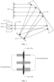
- FIG. 1 is a top view of a structure of a first spectrum processing apparatus according to an embodiment of this application.
- the spectrum processing apparatus includes: a port assembly 101, a lens assembly 102, a dispersive assembly 103, a spatial light modulator (spatial light modulator, SLM) 104, and a reflective element 105.
- the port assembly 101 includes N ports, where N is an integer greater than 1.
- the lens assembly 102 consists of M lenses, where M is an integer greater than or equal to 1 and less than or equal to N. Therefore, not all ports have their respective lenses.
- Each port in the port assembly 101 is configured to transmit an input first light beam to a lens corresponding to the port.
- Each lens in the lens assembly 102 is configured to adjust a width of the first light beam to obtain a second light beam, and transmit the second light beam to the reflective element 105.
- the reflective element 105 is configured to reflect the second light beam to the dispersive assembly 103.
- the dispersive assembly 103 is configured to decompose the second light beam into a plurality of sub-wavelength light beams, and transmit the plurality of sub-wavelength light beams to the reflective element 105.
- the reflective element 105 is further configured to reflect the plurality of sub-wavelength light beams to the spatial light modulator 104.
- the spatial light modulator 104 is configured to modulate the plurality of sub-wavelength light beams, and reflect at least one modulated sub-wavelength light beam to the reflective element 105.
- the reflective element 105 is further configured to reflect the at least one sub-wavelength light beam to the dispersive assembly 103.
- the dispersive assembly 103 is further configured to multiplex the at least one sub-wavelength light beam, and transmit a multiplexed light beam successively through the reflective element 105 and the lens assembly 102 to the port assembly 101.
- the ports in the port assembly 101 may have a plurality of arrangements.
- the ports may be sequentially arranged in the plane shown in FIG. 1 ; or the ports may be sequentially arranged in a plane perpendicular to the plane shown in FIG. 1 ; or the ports are distributed in both planes, that is, the port assembly 101 may also be an array with ports arranged in both rows and columns.
- the port assembly 101 may include a first column in which a first port 101a is located and a second column in which a second port 101b is located.
- a plurality of other ports may be sequentially arranged following the first port 101a.
- a plurality of other ports may be sequentially arranged following the second port 101b.
- FIG. 2 is a schematic diagram of a structure of a lens assembly. It may be understood that different lenses (including convex lenses, concave lenses, and the like) may converge or diverge light beams, and therefore may cause changes in a size of a light spot formed by a light beam striking the spatial light modulator 104.
- the lens assembly 102 in FIG. 2 includes an A lens 102a and a B lens 102b, where the A lens 102a is a convex lens, and after a first light beam passes through the A lens 102a, a width of the light beam decreases; and the B lens 102b is a concave lens, and after a first light beam passes through the B lens 102b, a width of the light beam increases.
- the lens assembly 102 may be a combination of M separate lenses.
- the lens assembly 102 may alternatively be an integral light transmitting surface structure, and different positions of the integral light transmitting surface structure are formed with different curvatures, to adjust the width of the first light beam.
- a structure of the lens assembly 102 is not specifically limited herein.
- FIG. 3 is a schematic diagram of changes in a beam waist radius after a light beam passes through a lens. If a first light beam does not pass through a lens or a curvature of the lens is infinite, a beam waist radius of a second light beam is ⁇ . If the first light beam passes through a lens with a focal length f, the beam waist radius of the second light beam is ⁇ '.
- the lenses in the lens assembly 102 are zoom lenses, for example, variable-focus liquid lenses.
- a focal length of each lens may be adjusted at any time, and a width of a first light beam passing through a same lens may also be adjusted at any time, so that each port can adapt to a plurality of functions.
- the dispersive assembly 103 may usually be a structure such as a grating or a prism, and can decompose the second light beam into a plurality of sub-wavelength light beams by wavelength, where each sub-wavelength light beam has a different wavelength. It may be understood that each sub-wavelength light beam is transmitted to a different position of the spatial light modulator 104. For example, after passing through the dispersive assembly 103, each second light beam is decomposed into two sub-wavelength light beams. Specifically, a quantity of sub-wavelength light beams decomposed from the second light beam after the second light beam passes through the dispersive assembly 103 is subject to practical applications. This is not limited herein.
- the spatial light modulator 104 may be specifically a plurality of different structures, for example, a liquid crystal modulator, a liquid crystal on silicon (Liquid Crystal on Silicon, LCoS) array, and a microelectromechanical system (Microelectromechanical Systems, MEMS) micromirror array. This is not specifically limited herein.
- the spatial light modulator 104 is specifically an LCoS.
- the LCoS has a pixelated region for modulation, and a reflection direction of each sub-wavelength light beam can be changed by modulating pixels of a corresponding wavelength region.
- the spatial light modulator 104 is specifically a MEMS micromirror array.
- the MEMS micromirror array consists of a plurality of rotatable reflectors, and a reflection direction of a sub-wavelength light beam is adjusted by rotating the reflectors.
- the spatial light modulator 104 changes a reflection direction of the sub-wavelength light beam such that the sub-wavelength light beam can be completely reflected to a port without any loss, or the sub-wavelength light beam cannot be reflected to the port, or a part of the sub-wavelength light beam can be reflected to the port.
- a specific modulation scheme of the spatial light modulator 104 is subject to practical applications, and this is not limited herein.
- each port in the port assembly 101 may be classified as an input port and an output port. It may be understood that each input port is configured to transmit the input first light beam to a lens corresponding to the input port, and after the dispersive assembly 103 multiplexes the sub-wavelength light beam reflected by the spatial light modulator 104, a multiplexed light beam is transmitted successively through the reflective element 105 and the lens assembly 102 to the output port.
- the port assembly includes at least two ports, and each lens in the lens assembly can adjust a width of a light beam from a port.
- a width of a light beam after passing through a lens may become larger or smaller, or may remain unchanged, and sizes of light spots formed by light beams of different widths on the SLM are also different. Therefore, the plurality of ports of the spectrum processing apparatus may be used to implement different functions, thereby enriching functions of the spectrum processing apparatus.
- FIG. 1 elaborates on the structure of the first spectrum processing apparatus in this application. The following describes other possible structures of the spectrum processing apparatus in this application.
- FIG. 4 is a side view of a structure of a second spectrum processing apparatus according to an embodiment of this application
- FIG. 5 is a top view of the structure of the second spectrum processing apparatus according to the embodiment of this application.
- the spectrum processing apparatus includes: a port assembly 101, a lens assembly 102, a dispersive assembly 103, a spatial light modulator 104, and a first lens 106. Descriptions of the port assembly 101, the lens assembly 102, the dispersive assembly 103, and the spatial light modulator 104 are similar to the related descriptions of the embodiment shown in FIG. 1 . Details are not described herein again.
- Each port in the port assembly 101 is configured to transmit an input first light beam to a lens corresponding to the port.
- Each lens in the lens assembly 102 is configured to adjust a width of the first light beam to obtain a second light beam, and transmit the second light beam to the dispersive assembly 103.
- the dispersive assembly 103 is configured to decompose the second light beam into a plurality of sub-wavelength light beams in a first plane (a plane shown in FIG. 5 ), and transmit the plurality of sub-wavelength light beams to the first lens 106.
- the first lens 106 is configured to refract the plurality of sub-wavelength light beams to the spatial light modulator 104 in the first plane, and transmit the plurality of sub-wavelength light beams in a second plane (a plane shown in FIG. 4 ) to the spatial light modulator 104, where the first plane is perpendicular to the second plane.
- the spatial light modulator 104 is configured to modulate the plurality of sub-wavelength light beams, and reflect at least one modulated sub-wavelength light beam to the first lens 106.
- the first lens 106 is further configured to refract the at least one sub-wavelength light beam to the dispersive assembly 103 in the first plane, and transmit the at least one sub-wavelength light beam to the dispersive assembly 103 in the second plane.
- the dispersive assembly 103 is further configured to multiplex the at least one sub-wavelength light beam, and transmit a multiplexed light beam through the lens assembly 102 to the port assembly 101.
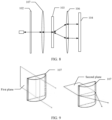
- FIG. 6 is a schematic diagram of a structure of the first lens.
- the first lens 106 is a cylindrical lens.
- a sub-wavelength light beam is refracted only in the first plane, and is not refracted in the second plane. Therefore, when seen from the perspective of the first plane, the first lens 106 can transmit the sub-wavelength light beams to the spatial light modulator 104 by means of refraction, and when seen from the perspective of the second plane, the sub-wavelength light beams are not projected together onto a same position of the spatial light modulator 104 due to the refraction.
- light beams emitted from a first port 101a, a second port 101b, and a third port 101c are finally projected onto different positions of the spatial light modulator 104, so that a light beam reflected by the spatial light modulator 104 can be transmitted to a corresponding port.
- FIG. 7 is a side view of a structure of a third spectrum processing apparatus according to an embodiment of this application
- FIG. 8 is a top view of the structure of the third spectrum processing apparatus according to the embodiment of this application.
- the spectrum processing apparatus includes: a port assembly 101, a lens assembly 102, a dispersive assembly 103, a spatial light modulator 104, a first lens 106, and a second lens 107. Descriptions of the port assembly 101, the lens assembly 102, the dispersive assembly 103, and the spatial light modulator 104 are similar to the related descriptions of the embodiment shown in FIG. 1 . Details are not described herein again.
- Each port in the port assembly 101 is configured to transmit an input first light beam to a lens corresponding to the port.
- Each lens in the lens assembly 102 is configured to adjust a width of the first light beam to obtain a second light beam, and transmit the second light beam to the second lens 107.
- the second lens 107 is configured to refract the second light beam to the dispersive assembly 103 in a second plane (a plane shown in FIG. 7 ).
- the dispersive assembly 103 is configured to decompose the second light beam into a plurality of sub-wavelength light beams in a first plane (a plane shown in FIG. 8 ), and transmit the plurality of sub-wavelength light beams to the first lens 106, where the first plane is perpendicular to the second plane.
- the first lens 106 is configured to refract the plurality of sub-wavelength light beams to the spatial light modulator 104 in the first plane and the second plane.
- the spatial light modulator 104 is configured to modulate the plurality of sub-wavelength light beams, and reflect at least one modulated sub-wavelength light beam to the first lens 106.
- the first lens 106 is further configured to refract the at least one sub-wavelength light beam to the dispersive assembly 103 in the first plane and the second plane.
- the dispersive assembly 103 is further configured to multiplex the at least one sub-wavelength light beam, and transmit a multiplexed light beam successively through the second lens 107 and the lens assembly 102 to the port assembly 101.
- the first lens 106 and the second lens 107 may use a standard 4f optical lens configuration.
- the second lens 107 is located between the dispersive assembly 103 and the lens assembly 102
- the first lens 106 is located between the dispersive assembly 103 and spatial light modulator 104
- a distance between the first lens 106 and the dispersive assembly 103 is equal to a focal length of the first lens 106
- a distance between the second lens 107 and the dispersive assembly 103 is equal to a focal length of the second lens 107
- a distance between the first lens 106 and spatial light modulator 104 is equal to the focal length of the first lens 106.
- the first lens 106 in this embodiment is different from the first lens 106 in the embodiment shown in FIG. 4 and FIG. 5 .
- the first lens 106 may be a common convex lens, which refracts the second light beam in both the first plane and the second plane.
- the second lens 107 is a cylindrical lens
- FIG. 9 is a schematic diagram of a structure of the second lens. Different from the cylindrical lens shown in FIG. 6 , when passing through the second lens 107, the first light beam is refracted only in the second plane, and is not refracted in the first plane.
- each port in the port assembly 101 may also be classified as an input port and an output port.
- FIG. 10 is a top view of a structure of a fourth spectrum processing apparatus according to an embodiment of this application. Specifically, an input port and an output port are placed side by side in a first plane. In an input direction, each input port is configured to transmit an input first light beam to a lens corresponding to the input port. In an output direction, a light beam multiplexed by a dispersive assembly 103 is transmitted through a lens assembly 102 to an output port corresponding to the input port. As can be seen from FIG.
- each port is classified as an input port and an output port, but the structure of the lens assembly 102, the dispersive assembly 103, a spatial light modulator 104, and a first lens 106 remains the same as the structure of the embodiment shown in FIG. 5 , except that the SLM adjusts a reflection direction of each sub-wavelength light beam such that a light beam multiplexed by the dispersive assembly 103 can be transmitted to the output port corresponding to the input port.
- an input port and an output port may also be distinguished in the manner shown in FIG. 10 . Details are not described herein again.
- the spectrum processing apparatus may further have a plurality of other structures different from the foregoing example.
- the following further provides a possible structure of the spectrum processing apparatus.
- FIG. 11 is a side view of a structure of a fifth spectrum processing apparatus according to an embodiment of this application
- FIG. 12 is a top view of the structure of the fifth spectrum processing apparatus according to the embodiment of this application.
- the spectrum processing apparatus includes: a port assembly 101, a lens assembly 102, a dispersive assembly 103, a spatial light modulator 104, a first lens 106, a second lens 107, and a third lens 108.
- Descriptions of the port assembly 101, the lens assembly 102, the dispersive assembly 103, and the spatial light modulator 104 are similar to the related descriptions of the embodiment shown in FIG. 1 . Details are not described herein again.
- Each input port in the port assembly 101 is configured to transmit an input first light beam to a lens corresponding to the port.
- Each lens in the lens assembly 102 is configured to adjust a width of the first light beam to obtain a second light beam, and transmit the second light beam to the third lens 108.
- the third lens 108 is configured to refract the second light beam to the second lens 107 in a first plane (a plane shown in FIG. 11 ).
- the second lens 107 is configured to refract the second light beam to the dispersive assembly 103 in a second plane (a plane shown in FIG. 10 ), where the first plane is perpendicular to the second plane.
- the dispersive assembly 103 is configured to decompose the second light beam into a plurality of sub-wavelength light beams in the first plane, and transmit the plurality of sub-wavelength light beams to the first lens 106.
- the first lens 106 is configured to refract the plurality of sub-wavelength light beams to the spatial light modulator 104 in the first plane and the second plane.
- the spatial light modulator 104 is configured to modulate the plurality of sub-wavelength light beams, and reflect at least one modulated sub-wavelength light beam to the first lens 106.
- the first lens 106 is further configured to refract the at least one sub-wavelength light beam to the dispersive assembly 103 in the first plane and the second plane.
- the dispersive assembly 103 is further configured to multiplex the at least one sub-wavelength light beam, and transmit a multiplexed light beam successively through the second lens 107, a third lens 108, and the lens assembly 102 to an output port corresponding to the input port.
- first lens 106 in this embodiment is similar to the first lens 106 in the embodiment shown in FIG. 7 and FIG. 8 . Details are not described herein again.
- the second lens 107 in this embodiment is different from the second lens 107 in the embodiment shown in FIG. 7 and FIG. 8 .
- the second lens 107 may be a common convex lens, which refracts the second light beam in both the first plane and the second plane.
- the third lens 108 is a cylindrical lens, and a structure of the third lens 108 is similar to that of the cylindrical lens shown in FIG. 6 . Details are not described herein again.
- the spectrum processing apparatus may further be provided with a polarization assembly 109.
- the polarization assembly 109 is adjacent to the lens assembly 102, and when seen from an input direction of a light beam, the polarization assembly 109 is located behind the lens assembly 102.
- the polarization assembly 109 is configured to separate polarizations of the second light beam to obtain a first polarized light beam (o light) and a second polarized light beam (e light), and further transmit the first polarized light beam and the second polarized light beam along the input direction, where the first polarized light beam and the second polarized light beam have mutually orthogonal polarization components.
- the polarization assembly 109 in an output direction of the light beam, the polarization assembly 109 is configured to restore the first polarized light beam and the second polarized light beam into a state before the separation, and further transmit a restored light beam along the output direction.
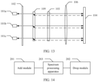
- FIG. 13 is a side view of a structure of a sixth spectrum processing apparatus according to an embodiment of this application.
- the spectrum processing apparatus includes: a port assembly 101, a lens assembly 102, a dispersive assembly 103, a spatial light modulator 104, a first lens 106, and a polarization assembly 109.
- Descriptions of the port assembly 101, the lens assembly 102, the dispersive assembly 103, and the spatial light modulator 104 are similar to the related descriptions of the embodiment shown in FIG. 1 . Details are not described herein again.
- the polarization assembly 109 decomposes a second light beam into a first polarized light beam (as shown by the solid line in FIG. 13 ) and a second polarized light beam (as shown by the dashed line in FIG. 13 ) in a second plane (a plane shown in FIG. 13 ).
- the polarization assembly 109 may also be arranged with reference to the manner shown in FIG. 13 . Details are not described herein again.
- insertion loss Insertion Loss, IL
- the spectrum processing apparatus shown in FIG. 4 is used as an example.
- a shorter distance between a port and an optic axis of the first lens 106 indicates smaller insertion loss of the port. Therefore, in design of distribution of ports, the ports may be symmetrically distributed with respect to the optic axis of the first lens 106, so as to differentiate insertion loss of the ports during use, and select corresponding ports to implement different functions. It may be understood that, corresponding to the different structures of the foregoing spectrum processing apparatuses, symmetrical distribution of the ports may also be different.
- the ports may be symmetrically distributed with respect to an optic axis of the reflective element 105 in a plane perpendicular to the plane shown in FIG. 1 .
- the ports may be symmetrically distributed with respect to an optic axis of the first lens 106 or the second lens 107.
- the ports may be symmetrically distributed with respect to an optic axis of the first lens 106, the second lens 107, or the third lens 108.
- the port assembly 101 has a total of five ports that are distributed in sequence, namely, ports 1 to 5. It is assumed that three different functions in total need to be allocated to the five ports, where one port is for wavelength blocking, two ports are for dynamic spectrum adjustment, and the other two ports are for spectrum scanning.
- the port 3 is located in the middle position and has the smallest insertion loss for being closest to the optic axis, the port 1 is for wavelength blocking.
- a light spot of a light beam projected from the port 1 onto the spatial light modulator 104 should be relatively small.
- the port 1 and the port 5 are located at edge positions and have the largest insertion loss.
- the port 1 and the port 5 are for spectrum scanning that is not sensitive to insertion loss.
- light spots of light beams projected from the port 1 and the port 5 onto the spatial light modulator 104 should be relatively small.
- the port 2 and the port 4 are located between the middle port and the edge ports and have relatively moderate insertion loss. Therefore, the port 2 and the port 4 are for dynamic spectrum adjustment.
- dynamic spectrum adjustment requires that a spectrum curve be relatively smooth after adjustment, and light spots of light beams projected from the port 2 and the port 4 onto the spatial light modulator 104 should be relatively large.
- FIG. 14 is a schematic diagram of a structure of a reconfigurable optical add-drop multiplexer (Reconfigurable Optical Add-Drop Multiplexer, ROADM) according to an embodiment of this application.
- the ROADM includes an add module 201, a drop module 202, and a spectrum processing apparatus 203.
- the spectrum processing apparatus 203 may be any one of the structures shown in FIG. 1 , FIG. 4 , FIG. 5, FIG. 7 , FIG. 8 , FIG. 10, FIG. 11, FIG. 12 , and FIG. 13 .
- the spectrum processing apparatus 203 is configured to implement spectrum processing functions such as dynamic spectrum adjustment, spectrum scanning, and wavelength blocking.
- the add module 201 may include a plurality of transmitters, and is configured to add a local optical wavelength signal from the port assembly of the spectrum processing apparatus 203.
- the drop module 202 may include a plurality of receivers, and is configured to drop a local optical wavelength signal from the port assembly of the spectrum processing apparatus 203.
- an embodiment shown in FIG. 15 provides a signal transmission method using a spectrum processing apparatus.
- the spectrum processing apparatus in this embodiment of this application is the structure of the spectrum processing apparatus in the embodiment shown in FIG. 1 . Details are not described herein again.
- the method includes the following steps.
- Each port in a port assembly transmits an input first light beam to a lens corresponding to the port.
- Each lens in a lens assembly adjusts a width of the first light beam to obtain a second light beam, and transmits the second light beam to a reflective element.
- the reflective element reflects the second light beam to a dispersive assembly.
- the dispersive assembly decomposes the second light beam into a plurality of sub-wavelength light beams, and transmits the plurality of sub-wavelength light beams to the reflective element.
- the reflective element reflects the plurality of sub-wavelength light beams to an SLM.
- the SLM modulates the plurality of sub-wavelength light beams, and reflects at least one modulated sub-wavelength light beam to the reflective element.
- the reflective element reflects the at least one sub-wavelength light beam to the dispersive assembly.
- the dispersive assembly multiplexes the at least one sub-wavelength light beam, and transmits a multiplexed light beam successively through the reflective element and the lens assembly to the port assembly.
- the port assembly includes at least two ports, and each lens in the lens assembly can adjust a width of a light beam from a port.
- a width of a light beam after passing through a lens may become larger or smaller, or may remain unchanged, and sizes of light spots formed by light beams of different widths on the SLM are also different. Therefore, the plurality of ports of the spectrum processing apparatus may be used to implement different functions, thereby enriching functions of the spectrum processing apparatus.
- FIG. 16 an embodiment shown in FIG. 16 provides another signal transmission method using a spectrum processing apparatus.
- the spectrum processing apparatus in this embodiment of this application is the structure of the spectrum processing apparatus in the embodiment shown in FIG. 4 and FIG. 5 . Details are not described herein again.
- the method includes the following steps.
- Each port in a port assembly transmits an input first light beam to a lens corresponding to the port.
- Each lens in a lens assembly adjusts a width of the first light beam to obtain a second light beam, and transmits the second light beam to a dispersive assembly.
- the dispersive assembly decomposes the second light beam into a plurality of sub-wavelength light beams in a first plane, and transmits the plurality of sub-wavelength light beams to a first lens.
- the first lens refracts the plurality of sub-wavelength light beams to an SLM in the first plane, and transmits the plurality of sub-wavelength light beams to the SLM in a second plane, where the second plane is perpendicular to the first plane.
- the SLM modulates the plurality of sub-wavelength light beams, and reflects at least one modulated sub-wavelength light beam to the first lens.
- the first lens refracts the at least one sub-wavelength light beam to the dispersive assembly in the first plane, and transmits the at least one sub-wavelength light beam to the dispersive assembly in the second plane.
- the dispersive assembly multiplexes the at least one sub-wavelength light beam, and transmits a multiplexed light beam through the lens assembly to the port assembly.
- an embodiment shown in FIG. 17 provides another signal transmission method using a spectrum processing apparatus.
- the spectrum processing apparatus in this embodiment of this application is the structure of the spectrum processing apparatus in the embodiment shown in FIG. 7 and FIG. 8 . Details are not described herein again.
- the method includes the following steps.
- Each port in a port assembly transmits an input first light beam to a lens corresponding to the port.
- Each lens in a lens assembly adjusts a width of the first light beam to obtain a second light beam, and transmits the second light beam to a second lens.
- the second lens refracts the second light beam to a dispersive assembly in a second plane.
- the dispersive assembly decomposes the second light beam into a plurality of sub-wavelength light beams in a first plane, and transmits the plurality of sub-wavelength light beams to a first lens, where the first plane is perpendicular to the second plane.
- the first lens refracts the plurality of sub-wavelength light beams to an SLM in the first plane and the second plane.
- the SLM modulates the plurality of sub-wavelength light beams, and reflects at least one modulated sub-wavelength light beam to the first lens.
- the first lens refracts the at least one sub-wavelength light beam to the dispersive assembly in the first plane and the second plane.
- the dispersive assembly multiplexes the at least one sub-wavelength light beam, and transmits a multiplexed light beam successively through the second lens and the lens assembly to the port assembly.
Landscapes
- Physics & Mathematics (AREA)
- General Physics & Mathematics (AREA)
- Optics & Photonics (AREA)
- Optical Modulation, Optical Deflection, Nonlinear Optics, Optical Demodulation, Optical Logic Elements (AREA)
- Engineering & Computer Science (AREA)
- Computer Networks & Wireless Communication (AREA)
- Signal Processing (AREA)
- Mechanical Light Control Or Optical Switches (AREA)
Description
- This application relates to the field of optical communications, and in particular, to a spectrum processing apparatus and a reconfigurable optical add-drop multiplexer.
- In recent years, with the vigorous development of network data services, capacities of optical transmission systems have become increasingly large, and requirements for optical networks have also become increasingly high. High-performance and flexibly configurable optical networks are the development direction of future optical networks, and the use of apparatuses having a spectrum processing capability is required in many cases.
- These spectrum processing apparatuses having a spectrum processing capability can flexibly change spectral characteristics or can be used to detect a spectrum based on requirements of optical networks. The spectrum processing apparatuses are important components for high-performance intelligent optical networks. A spectrum processing apparatus used for wavelength blocking is used as an example. A dispersive assembly separates wavelengths of an incident light beam, and light beams with different wavelengths are incident onto different positions of a spatial light modulator (spatial light modulator, SLM). The SLM determines wavelengths of light beams that can be reflected to an output port and wavelengths to be blocked.
- The spectrum processing apparatus used for wavelength blocking requires bandwidth in each wavelength channel to be as large as possible, and then a light spot formed on the SLM needs to be as small as possible. However, if the spectrum processing apparatus is used for overall spectrum adjustment, small light spots on the SLM may produce glitches in the spectrum, which makes it difficult to form a smooth spectrum. In other words, the spectrum processing apparatus used for wavelength blocking is not suitable for overall spectrum adjustment. Therefore, a current spectrum processing apparatus has a limited function.
-
US 2006/0067611 A1 describes an optical coupling device including: at least a first input port for delivering an optical input signal beam that includes a plurality of wavelength channels; at least a first optical output port for receiving an optical output signal beam; a wavelength dispersion element for spatially separating the plurality of wavelength channels in the optical input signal beam to form a plurality of spatially separated wavelength channel beams; an optical coupling device for independently modifying the phase of each of the spatially separated wavelength channel beams such that, for at least one wavelength channel beam, a selected fraction of the light is coupled to the first output port and a fraction of the light is coupled away from the first output port. - The invention provides a spectrum processing apparatus and a reconfigurable optical add-drop multiplexer, thereby enriching functions of the spectrum processing apparatus according to the appended claims.
- According to a first aspect, an embodiment of this application provides a spectrum processing apparatus, including: a port assembly, a lens assembly, a dispersive assembly, a spatial light modulator SLM, and a reflective element, where the port assembly includes N ports, and the lens assembly includes M lenses, where N is an integer greater than 1, and M is an integer greater than or equal to 1 and less than or equal to N. Each port in the port assembly is configured to transmit an input first light beam to a lens corresponding to the port. Each lens in the lens assembly is configured to adjust a width of the first light beam to obtain a second light beam, and transmit the second light beam to the reflective element. The reflective element is configured to reflect the second light beam to the dispersive assembly. The dispersive assembly is configured to decompose the second light beam into a plurality of sub-wavelength light beams, and transmit the plurality of sub-wavelength light beams to the reflective element. The reflective element is further configured to reflect the plurality of sub-wavelength light beams to the SLM. The SLM is configured to modulate the plurality of sub-wavelength light beams, and reflect at least one modulated sub-wavelength light beam to the reflective element. The reflective element is further configured to reflect the at least one sub-wavelength light beam to the dispersive assembly. The dispersive assembly is further configured to multiplex the at least one sub-wavelength light beam, and transmit a multiplexed light beam successively through the reflective element and the lens assembly to the port assembly.
- It should be understood that the SLM may be a liquid crystal modulator, a liquid crystal on silicon (Liquid Crystal on Silicon, LCoS) array, a microelectromechanical system (Microelectromechanical Systems, MEMS) micromirror array, or the like. The SLM changes a reflection direction of the sub-wavelength light beam such that the sub-wavelength light beam can be completely reflected to a port without any loss, or the sub-wavelength light beam cannot be reflected to the port, or a part of the sub-wavelength light beam can be reflected to the port.
- In this implementation, due to different sizes of light spots on the SLM, corresponding light beams are applicable to different functions. For example, a light beam corresponding to a small light spot is applicable to a wavelength blocking function, while a light beam corresponding to a large light spot is applicable to overall spectrum adjustment. In the spectrum processing apparatus provided in this application, the port assembly includes at least two ports, and each lens in the lens assembly can adjust a width of a light beam from a port. To be specific, a width of a light beam after passing through a lens may become larger or smaller, or may remain unchanged, and sizes of light spots formed by light beams of different widths on the SLM are also different. Therefore, the plurality of ports of the spectrum processing apparatus may be used to implement different functions, thereby enriching functions of the spectrum processing apparatus. A focal length of each lens of the M lenses is adjustable.
- According to the claimed invention, the M lenses are all zoom lenses, for example, variable-focus liquid lenses. A focal length of each lens may be adjusted at any time, and a width of a first light beam passing through a same lens may also be adjusted at any time, so that each port can adapt to a plurality of functions.
- Optionally, in some possible implementations, each port includes an input port and an output port; and each port in the port assembly being configured to transmit an input first light beam to a lens corresponding to the port includes:
- each input port being configured to transmit the input first light beam to a lens corresponding to the input port; and
- the dispersive assembly being further configured to multiplex the at least one sub-wavelength light beam, and transmit a multiplexed light beam successively through the reflective element and the lens assembly to the port assembly includes:
the dispersive assembly being further configured to multiplex the at least one sub-wavelength light beam, and transmit the multiplexed light beam successively through the reflective element and the lens assembly to the output port corresponding to the input port. - In this implementation, each port may include an input port and an output port, and then an input light beam and an output light beam are separated on a transmission path, thereby improving applicability of this solution.
- Optionally, in some possible implementations, the spectrum processing apparatus further includes a polarization assembly, and the polarization assembly is located between the lens assembly and the reflective element; and the polarization assembly is configured to separate polarizations of the second light beam into a first polarized light beam and a second polarized light beam, and transmit the first polarized light beam and the second polarized light beam to the dispersive assembly, where the first polarized light beam and the second polarized light beam have mutually orthogonal polarization components.
- In this implementation, the spectrum processing apparatus may further be provided with the polarization assembly, thereby improving scalability of this solution.
- Optionally, in some possible implementations, the N ports are symmetrically distributed with respect to an optic axis of the reflective element.
- In this implementation, applicable functions of the spectrum proce ssing apparatus not only have different requirements for sizes of light spots formed on the SLM, but also have different requirements for insertion loss (Insertion Loss, IL) of each port. In optical design, a shorter distance between a port and the optic axis of the reflective element indicates smaller insertion loss of the port. Therefore, in design of distribution of ports, the ports may be symmetrically distributed with respect to the optic axis of the reflective element, so as to differentiate insertion loss of the ports during use, and select corresponding ports to implement different functions.
- According to a second aspect, an embodiment of this application provides another spectrum processing apparatus, including: a port assembly, a lens assembly, a dispersive assembly, a spatial light modulator SLM, and a first lens, where the port assembly includes N ports, and the lens assembly includes M lenses, where N is an integer greater than 1, and M is an integer greater than or equal to 1 and less than or equal to N. Each port in the port assembly is configured to transmit an input first light beam to a lens corresponding to the port. Each lens in the lens assembly is configured to adjust a width of the first light beam to obtain a second light beam, and transmit the second light beam to the dispersive assembly. The dispersive assembly is configured to decompose the second light beam into a plurality of sub-wavelength light beams in a first plane, and transmit the plurality of sub-wavelength light beams to the first lens. The first lens is configured to refract the plurality of sub-wavelength light beams to the SLM in the first plane, and transmit the plurality of sub-wavelength light beams to the SLM in a second plane, where the second plane is perpendicular to the first plane. The SLM is configured to modulate the plurality of sub-wavelength light beams, and reflect at least one modulated sub-wavelength light beam to the first lens. The first lens is further configured to refract the at least one sub-wavelength light beam to the dispersive assembly in the first plane, and transmit the at least one sub-wavelength light beam to the dispersive assembly in the second plane. The dispersive assembly is further configured to multiplex the at least one sub-wavelength light beam, and transmit a multiplexed light beam through the lens assembly to the port assembly. A focal length of each lens of the M lenses is adjustable.
- According to the claimed invention, the M lenses are all zoom lenses.
- Optionally, in some possible implementations, each port includes an input port and an output port; and
each port in the port assembly being configured to transmit an input first light beam to a lens corresponding to the port includes: - each input port being configured to transmit the input first light beam to a lens corresponding to the input port; and
- the dispersive assembly being further configured to multiplex the at least one sub-wavelength light beam, and transmit a multiplexed light beam through the lens assembly to the port assembly includes:
the dispersive assembly being further configured to multiplex the at least one sub-wavelength light beam, and transmit the multiplexed light beam through the lens assembly to the output port corresponding to the input port. - Optionally, in some possible implementations, the spectrum processing apparatus further includes a polarization assembly, and the polarization assembly is located between the lens assembly and the dispersive assembly; and
the polarization assembly is configured to separate polarizations of the second light beam into a first polarized light beam and a second polarized light beam, and transmit the first polarized light beam and the second polarized light beam to the dispersive assembly, where the first polarized light beam and the second polarized light beam have mutually orthogonal polarization components. - Optionally, in some possible implementations, the N ports are symmetrically distributed with respect to an optic axis of the first lens.
- According to a third aspect, an embodiment of this application provides another spectrum processing apparatus, including: a port assembly, a lens assembly, a dispersive assembly, a spatial light modulator SLM, a first lens, and a second lens, where the port assembly includes N ports, and the lens assembly includes M lenses, where N is an integer greater than 1, and M is an integer greater than or equal to 1 and less than or equal to N. Each port in the port assembly is configured to transmit an input first light beam to a lens corresponding to the port. Each lens in the lens assembly is configured to adjust a width of the first light beam to obtain a second light beam, and transmit the second light beam to the second lens. The second lens is configured to refract the second light beam to the dispersive assembly in a second plane. The dispersive assembly is configured to decompose the second light beam into a plurality of sub-wavelength light beams in a first plane, and transmit the plurality of sub-wavelength light beams to the first lens, where the first plane is perpendicular to the second plane. The first lens is configured to refract the plurality of sub-wavelength light beams to the SLM in the first plane and the second plane. The SLM is configured to modulate the plurality of sub-wavelength light beams, and reflect at least one modulated sub-wavelength light beam to the first lens. The first lens is further configured to refract the at least one sub-wavelength light beam to the dispersive assembly in the first plane and the second plane. The dispersive assembly is further configured to multiplex the at least one sub-wavelength light beam, and transmit a multiplexed light beam successively through the second lens and the lens assembly to the port assembly. A focal length of each lens of the M lenses is adjustable.
- Optionally, in some possible implementations, the second lens is located between the dispersive assembly and the lens assembly, the first lens is located between the dispersive assembly and the SLM, a distance between the first lens and the dispersive assembly is equal to a focal length of the first lens, a distance between the second lens and the dispersive assembly is equal to a focal length of the second lens, and a distance between the first lens and the SLM is equal to the focal length of the first lens.
- In this implementation, the first lens and the second lens use a standard 4f optical lens configuration, and a transmission path of a light beam is more regular, thereby improving implementability of this solution.
- According to the claimed invention, the M lenses are all zoom lenses.
- Optionally, in some possible implementations, each port includes an input port and an output port; and
each port in the port assembly being configured to transmit an input first light beam to a lens corresponding to the port includes: - each input port being configured to transmit the input first light beam to a lens corresponding to the input port; and
- the dispersive assembly being further configured to multiplex the at least one sub-wavelength light beam, and transmit a multiplexed light beam successively through the second lens and the lens assembly to the port assembly includes:
the dispersive assembly being further configured to multiplex the at least one sub-wavelength light beam, and transmit the multiplexed light beam successively through the second lens and the lens assembly to the output port corresponding to the input port. - Optionally, in some possible implementations, the spectrum processing apparatus further includes a polarization assembly, and the polarization assembly is located between the lens assembly and the second lens; and
the polarization assembly is configured to separate polarizations of the second light beam into a first polarized light beam and a second polarized light beam, and transmit the first polarized light beam and the second polarized light beam to the first lens, where the first polarized light beam and the second polarized light beam have mutually orthogonal polarization components. - Optionally, in some possible implementations, the N ports are symmetrically distributed with respect to an optic axis of the first lens or the second lens.
- According to a fourth aspect, an embodiment of this application provides a reconfigurable optical add-drop multiplexer (Reconfigurable Optical Add-Drop Multiplexer, ROADM), including: an add module, a drop module, and the spectrum processing apparatus according to any one of the first aspect to the third aspect. The spectrum processing apparatus is configured to implement a spectrum processing function. The add module is configured to add a local optical wavelength signal from the port assembly of the spectrum processing apparatus. The drop module is configured to drop a local optical wavelength signal from the port assembly of the spectrum processing apparatus.
- According to a fifth aspect, an embodiment of this application provides a spectrum processing method, applied to a spectrum processing apparatus, where the spectrum processing apparatus includes: a port assembly, a lens assembly, a dispersive assembly, a spatial light modulator SLM, and a reflective element, where the port assembly includes N ports, and the lens assembly includes M lenses, where N is an integer greater than 1, and M is an integer greater than or equal to 1 and less than or equal to N.
- The method includes: transmitting, by each port in the port assembly, an input first light beam to a lens corresponding to each port;
adjusting, by each lens in the lens assembly, a width of the first light beam to obtain a second light beam, and transmitting the second light beam to the reflective element; reflecting, by the reflective element, the second light beam to the dispersive assembly; decomposing, by the dispersive assembly, the second light beam into a plurality of sub-wavelength light beams, and transmitting the plurality of sub-wavelength light beams to the reflective element; reflecting, by the reflective element, the plurality of sub-wavelength light beams to the SLM; modulating, by the SLM, the plurality of sub-wavelength light beams, and reflecting at least one modulated sub-wavelength light beam to the reflective element; reflecting, by the reflective element, the at least one sub-wavelength light beam to the dispersive assembly; and multiplexing, by the dispersive assembly, the at least one sub-wavelength light beam, and transmitting a multiplexed light beam successively through the reflective element and the lens assembly to the port assembly. A focal length of each lens of the M lenses is adjustable. - According to the claimed invention, the M lenses are all zoom lenses.
- Optionally, in some possible implementations, each port includes an input port and an output port; and
the transmitting, by each port in the port assembly, an input first light beam to a lens corresponding to each port includes: - transmitting, by each input port, the input first light beam to a lens corresponding to the input port; and
- the multiplexing, by the dispersive assembly, the at least one sub-wavelength light beam, and transmitting a multiplexed light beam successively through the reflective element and the lens assembly to the port assembly includes:
multiplexing, by the dispersive assembly, the at least one sub-wavelength light beam, and transmitting the multiplexed light beam successively through the reflective element and the lens assembly to the output port corresponding to the input port. - Optionally, in some possible implementations, the spectrum processing apparatus further includes a polarization assembly, and the polarization assembly is located between the lens assembly and the reflective element; and the method further includes:
- separating, by the polarization assembly, polarizations of the second light beam into a first polarized light beam and a second polarized light beam, and transmitting the first polarized light beam and the second polarized light beam to the dispersive assembly, where the first polarized light beam and the second polarized light beam have mutually orthogonal polarization components.
- Optionally, in some possible implementations, the N ports are symmetrically distributed with respect to an optic axis of the reflective element.
- According to a sixth aspect, an embodiment of this application provides another spectrum processing method, applied to a spectrum processing apparatus, where the spectrum processing apparatus includes: a port assembly, a lens assembly, a dispersive assembly, a spatial light modulator SLM, and a first lens, where the port assembly includes N ports, and the lens assembly includes M lenses, where N is an integer greater than 1, and M is an integer greater than or equal to 1 and less than or equal to N.
- The method includes: transmitting, by each port in the port assembly, an input first light beam to a lens corresponding to each port; adjusting, by each lens in the lens assembly, a width of the first light beam to obtain a second light beam, and transmitting the second light beam to the dispersive assembly; decomposing, by the dispersive assembly, the second light beam into a plurality of sub-wavelength light beams in a first plane, and transmitting the plurality of sub-wavelength light beams to the first lens; refracting, by the first lens, the plurality of sub-wavelength light beams to the SLM in the first plane, and transmitting the plurality of sub-wavelength light beams to the SLM in a second plane, where the second plane is perpendicular to the first plane; modulating, by the SLM, the plurality of sub-wavelength light beams, and reflecting at least one modulated sub-wavelength light beam to the first lens; refracting, by the first lens, the at least one sub-wavelength light beam to the dispersive assembly in the first plane, and transmitting the at least one sub-wavelength light beam to the dispersive assembly in the second plane; and multiplexing, by the dispersive assembly, the at least one sub-wavelength light beam, and transmitting a multiplexed light beam through the lens assembly to the port assembly. A focal length of each lens of the M lenses is adjustable.
- According to the claimed invention, the M lenses are all zoom lenses.
- Optionally, in some possible implementations, each port includes an input port and an output port; and
the transmitting, by each port in the port assembly, an input first light beam to a lens corresponding to each port includes: - transmitting, by each input port, the input first light beam to a lens corresponding to the input port; and
- the multiplexing, by the dispersive assembly, the at least one sub-wavelength light beam, and transmitting a multiplexed light beam through the lens assembly to the port assembly includes:
multiplexing, by the dispersive assembly, the at least one sub-wavelength light beam, and transmitting the multiplexed light beam through the lens assembly to the output port corresponding to the input port. - Optionally, in some possible implementations, the spectrum processing apparatus further includes a polarization assembly, and the polarization assembly is located between the lens assembly and the dispersive assembly; and
the method further includes: separating, by the polarization assembly, polarizations of the second light beam into a first polarized light beam and a second polarized light beam, and transmitting the first polarized light beam and the second polarized light beam to the dispersive assembly, where the first polarized light beam and the second polarized light beam have mutually orthogonal polarization components. - Optionally, in some possible implementations, the N ports are symmetrically distributed with respect to an optic axis of the first lens.
- According to a seventh aspect, an embodiment of this application provides another spectrum processing method, applied to a spectrum processing apparatus, where the spectrum processing apparatus includes: a port assembly, a lens assembly, a dispersive assembly, a spatial light modulator SLM, a first lens, and a second lens, where the port assembly includes N ports, and the lens assembly includes M lenses, where N is an integer greater than 1, and M is an integer greater than or equal to 1 and less than or equal to N.
- The method includes: transmitting, by each port in the port assembly, an input first light beam to a lens corresponding to each port; adjusting, by each lens in the lens assembly, a width of the first light beam to obtain a second light beam, and transmitting the second light beam to the second lens; refracting, by the second lens, the second light beam to the dispersive assembly in a second plane; decomposing, by the dispersive assembly, the second light beam into a plurality of sub-wavelength light beams in a first plane, and transmitting the plurality of sub-wavelength light beams to the first lens, where the first plane is perpendicular to the second plane; refracting, by the first lens, the plurality of sub-wavelength light beams to the SLM in the first plane and the second plane; modulating, by the SLM, the plurality of sub-wavelength light beams, and reflecting at least one modulated sub-wavelength light beam to the first lens; refracting, by the first lens, the at least one sub-wavelength light beam to the dispersive assembly in the first plane and the second plane; and multiplexing, by the dispersive assembly, the at least one sub-wavelength light beam, and transmitting a multiplexed light beam successively through the second lens and the lens assembly to the port assembly. A focal length of each lens of the M lenses is adjustable.
- Optionally, in some possible implementations, the second lens is located between the dispersive assembly and the lens assembly, the first lens is located between the dispersive assembly and the SLM, a distance between the first lens and the dispersive assembly is equal to a focal length of the first lens, a distance between the second lens and the dispersive assembly is equal to a focal length of the second lens, and a distance between the first lens and the SLM is equal to the focal length of the first lens.
- According to the claimed invention, the M lenses are all zoom lenses.
- Optionally, in some possible implementations, each port includes an input port and an output port; and
the transmitting, by each port in the port assembly, an input first light beam to a lens corresponding to each port includes: - transmitting, by each input port, the input first light beam to a lens corresponding to the input port; and
- the multiplexing, by the dispersive assembly, the at least one sub-wavelength light beam, and transmitting a multiplexed light beam successively through the second lens and the lens assembly to the port assembly includes:
multiplexing, by the dispersive assembly, the at least one sub-wavelength light beam, and transmitting the multiplexed light beam successively through the second lens and the lens assembly to the output port corresponding to the input port. - Optionally, in some possible implementations, the spectrum processing apparatus further includes a polarization assembly, and the polarization assembly is located between the lens assembly and the second lens; and
the method further includes: separating, by the polarization assembly, polarizations of the second light beam into a first polarized light beam and a second polarized light beam, and transmitting the first polarized light beam and the second polarized light beam to the first lens, where the first polarized light beam and the second polarized light beam have mutually orthogonal polarization components. - Optionally, in some possible implementations, the N ports are symmetrically distributed with respect to an optic axis of the first lens or the second lens.
- It can be learned from the foregoing technical solutions that the embodiments of this application have the following advantages:
- In the embodiments of this application, due to different sizes of light spots on the SLM, corresponding light beams are applicable to different functions. For example, a light beam corresponding to a small light spot is applicable to a wavelength blocking function, while a light beam corresponding to a large light spot is applicable to overall spectrum adjustment. In the spectrum processing apparatus provided in this application, the port assembly includes at least two ports, and each lens in the lens assembly can adjust a width of a light beam from a port. To be specific, a width of a light beam after passing through a lens may become larger or smaller, or may remain unchanged, and sizes of light spots formed by light beams of different widths on the SLM are also different. Therefore, the plurality of ports of the spectrum processing apparatus may be used to implement different functions, thereby enriching functions of the spectrum processing apparatus.
-
-
FIG. 1 is a top view of a structure of a first spectrum processing apparatus according to an embodiment of this application; -
FIG. 2 is a schematic diagram of a structure of a lens assembly; -
FIG. 3 is a schematic diagram of changes in a beam waist radius after a light beam passes through a lens; -
FIG. 4 is a side view of a structure of a second spectrum processing apparatus according to an embodiment of this application; -
FIG. 5 is a top view of the structure of the second spectrum processing apparatus according to the embodiment of this application; -
FIG. 6 is a schematic diagram of a structure of a first lens; -
FIG. 7 is a side view of a structure of a third spectrum processing apparatus according to an embodiment of this application; -
FIG. 8 is a top view of the structure of the third spectrum processing apparatus according to the embodiment of this application; -
FIG. 9 is a schematic diagram of a structure of a second lens; -
FIG. 10 is a top view of a structure of a fourth spectrum processing apparatus according to an embodiment of this application; -
FIG. 11 is a side view of a structure of a fifth spectrum processing apparatus according to an embodiment of this application; -
FIG. 12 is a top view of the structure of the fifth spectrum processing apparatus according to the embodiment of this application; -
FIG. 13 is a side view of a structure of a sixth spectrum processing apparatus according to an embodiment of this application; -
FIG. 14 is a schematic diagram of a structure of a ROADM according to an embodiment of this application; -
FIG. 15 is a schematic diagram of an embodiment of a signal transmission method using a spectrum processing apparatus according to an embodiment of this application; -
FIG. 16 is a schematic diagram of an embodiment of another signal transmission method using a spectrum processing apparatus according to an embodiment of this application; and -
FIG. 17 is a schematic diagram of an embodiment of another signal transmission method using a spectrum processing apparatus according to an embodiment of this application. - Embodiments of this application provide a spectrum processing apparatus and a reconfigurable optical add-drop multiplexer, thereby enriching functions of the spectrum processing apparatus. In the specification, claims, and accompanying drawings of this application, the terms "first", "second", "third", "fourth", and the like (if existent) are intended to distinguish between similar objects but do not necessarily indicate a specific order or sequence. It should be understood that data termed in such a way are interchangeable in proper circumstances so that the embodiments described herein can be implemented in other orders than the order illustrated or described herein. Moreover, the terms "include", "have" and any other variants thereof mean to cover the non-exclusive inclusion, for example, a process, method, system, product, or device that includes a list of steps or units is not necessarily limited to the clearly listed steps or units, but may include other steps or units not clearly listed or inherent to such a process, method, product, or device.
-
FIG. 1 is a top view of a structure of a first spectrum processing apparatus according to an embodiment of this application. The spectrum processing apparatus includes: aport assembly 101, alens assembly 102, adispersive assembly 103, a spatial light modulator (spatial light modulator, SLM) 104, and areflective element 105. Theport assembly 101 includes N ports, where N is an integer greater than 1. Thelens assembly 102 consists of M lenses, where M is an integer greater than or equal to 1 and less than or equal to N. Therefore, not all ports have their respective lenses. - Each port in the
port assembly 101 is configured to transmit an input first light beam to a lens corresponding to the port. Each lens in thelens assembly 102 is configured to adjust a width of the first light beam to obtain a second light beam, and transmit the second light beam to thereflective element 105. Thereflective element 105 is configured to reflect the second light beam to thedispersive assembly 103. Thedispersive assembly 103 is configured to decompose the second light beam into a plurality of sub-wavelength light beams, and transmit the plurality of sub-wavelength light beams to thereflective element 105. Thereflective element 105 is further configured to reflect the plurality of sub-wavelength light beams to the spatiallight modulator 104. The spatiallight modulator 104 is configured to modulate the plurality of sub-wavelength light beams, and reflect at least one modulated sub-wavelength light beam to thereflective element 105. Thereflective element 105 is further configured to reflect the at least one sub-wavelength light beam to thedispersive assembly 103. Thedispersive assembly 103 is further configured to multiplex the at least one sub-wavelength light beam, and transmit a multiplexed light beam successively through thereflective element 105 and thelens assembly 102 to theport assembly 101. - It should be noted that the ports in the
port assembly 101 may have a plurality of arrangements. For example, the ports may be sequentially arranged in the plane shown inFIG. 1 ; or the ports may be sequentially arranged in a plane perpendicular to the plane shown inFIG. 1 ; or the ports are distributed in both planes, that is, theport assembly 101 may also be an array with ports arranged in both rows and columns. This is not specifically limited herein. For example, when seen from the perspective shown inFIG. 1 , theport assembly 101 may include a first column in which afirst port 101a is located and a second column in which asecond port 101b is located. In the first column, a plurality of other ports may be sequentially arranged following thefirst port 101a. Similarly, in the second column, a plurality of other ports may be sequentially arranged following thesecond port 101b. -
FIG. 2 is a schematic diagram of a structure of a lens assembly. It may be understood that different lenses (including convex lenses, concave lenses, and the like) may converge or diverge light beams, and therefore may cause changes in a size of a light spot formed by a light beam striking the spatiallight modulator 104. For example, thelens assembly 102 inFIG. 2 includes anA lens 102a and aB lens 102b, where theA lens 102a is a convex lens, and after a first light beam passes through theA lens 102a, a width of the light beam decreases; and theB lens 102b is a concave lens, and after a first light beam passes through theB lens 102b, a width of the light beam increases. - It should be noted that, if a width of a first light beam emitted from some port meets requirements, no lens may be arranged on a transmission path of the first light beam to change the width of the light beam, or a plane mirror may be placed at a corresponding position of the
lens assembly 102 only to transmit the first light beam. In practical applications, thelens assembly 102 may be a combination of M separate lenses. Certainly, another design may also be possible. For example, thelens assembly 102 may alternatively be an integral light transmitting surface structure, and different positions of the integral light transmitting surface structure are formed with different curvatures, to adjust the width of the first light beam. A structure of thelens assembly 102 is not specifically limited herein. - It should be noted that a focal length of a lens meeting requirements may be pre-calculated based on an actual required width of a light beam. A possible implementation is provided below, where a width of a light beam is represented by a beam waist radius.
FIG. 3 is a schematic diagram of changes in a beam waist radius after a light beam passes through a lens. If a first light beam does not pass through a lens or a curvature of the lens is infinite, a beam waist radius of a second light beam is ω. If the first light beam passes through a lens with a focal length f, the beam waist radius of the second light beam is ω'. According to Gaussian optics, the focal length f of the lens may be selected according to the following formula:
- According to the claimed invention, the lenses in the
lens assembly 102 are zoom lenses, for example, variable-focus liquid lenses. A focal length of each lens may be adjusted at any time, and a width of a first light beam passing through a same lens may also be adjusted at any time, so that each port can adapt to a plurality of functions. - It should be noted that, the
dispersive assembly 103 may usually be a structure such as a grating or a prism, and can decompose the second light beam into a plurality of sub-wavelength light beams by wavelength, where each sub-wavelength light beam has a different wavelength. It may be understood that each sub-wavelength light beam is transmitted to a different position of the spatiallight modulator 104. For example, after passing through thedispersive assembly 103, each second light beam is decomposed into two sub-wavelength light beams. Specifically, a quantity of sub-wavelength light beams decomposed from the second light beam after the second light beam passes through thedispersive assembly 103 is subject to practical applications. This is not limited herein. - Optionally, the spatial
light modulator 104 may be specifically a plurality of different structures, for example, a liquid crystal modulator, a liquid crystal on silicon (Liquid Crystal on Silicon, LCoS) array, and a microelectromechanical system (Microelectromechanical Systems, MEMS) micromirror array. This is not specifically limited herein. - For example, the spatial
light modulator 104 is specifically an LCoS. The LCoS has a pixelated region for modulation, and a reflection direction of each sub-wavelength light beam can be changed by modulating pixels of a corresponding wavelength region. For example, the spatiallight modulator 104 is specifically a MEMS micromirror array. The MEMS micromirror array consists of a plurality of rotatable reflectors, and a reflection direction of a sub-wavelength light beam is adjusted by rotating the reflectors. Specifically, after a sub-wavelength light beam is incident onto the spatiallight modulator 104, the spatiallight modulator 104 changes a reflection direction of the sub-wavelength light beam such that the sub-wavelength light beam can be completely reflected to a port without any loss, or the sub-wavelength light beam cannot be reflected to the port, or a part of the sub-wavelength light beam can be reflected to the port. A specific modulation scheme of the spatiallight modulator 104 is subject to practical applications, and this is not limited herein. - Optionally, each port in the
port assembly 101 may be classified as an input port and an output port. It may be understood that each input port is configured to transmit the input first light beam to a lens corresponding to the input port, and after thedispersive assembly 103 multiplexes the sub-wavelength light beam reflected by the spatiallight modulator 104, a multiplexed light beam is transmitted successively through thereflective element 105 and thelens assembly 102 to the output port. - In this embodiment of this application, due to different sizes of light spots on the SLM, corresponding light beams are applicable to different functions. For example, a light beam corresponding to a small light spot is applicable to a wavelength blocking function, while a light beam corresponding to a large light spot is applicable to overall spectrum adjustment. In the spectrum processing apparatus provided in this application, the port assembly includes at least two ports, and each lens in the lens assembly can adjust a width of a light beam from a port. To be specific, a width of a light beam after passing through a lens may become larger or smaller, or may remain unchanged, and sizes of light spots formed by light beams of different widths on the SLM are also different. Therefore, the plurality of ports of the spectrum processing apparatus may be used to implement different functions, thereby enriching functions of the spectrum processing apparatus.
-
FIG. 1 elaborates on the structure of the first spectrum processing apparatus in this application. The following describes other possible structures of the spectrum processing apparatus in this application. - Referring to
FIG. 4 andFIG. 5 ,FIG. 4 is a side view of a structure of a second spectrum processing apparatus according to an embodiment of this application, andFIG. 5 is a top view of the structure of the second spectrum processing apparatus according to the embodiment of this application. The spectrum processing apparatus includes: aport assembly 101, alens assembly 102, adispersive assembly 103, a spatiallight modulator 104, and afirst lens 106. Descriptions of theport assembly 101, thelens assembly 102, thedispersive assembly 103, and the spatiallight modulator 104 are similar to the related descriptions of the embodiment shown inFIG. 1 . Details are not described herein again. - Each port in the
port assembly 101 is configured to transmit an input first light beam to a lens corresponding to the port. Each lens in thelens assembly 102 is configured to adjust a width of the first light beam to obtain a second light beam, and transmit the second light beam to thedispersive assembly 103. Thedispersive assembly 103 is configured to decompose the second light beam into a plurality of sub-wavelength light beams in a first plane (a plane shown inFIG. 5 ), and transmit the plurality of sub-wavelength light beams to thefirst lens 106. Thefirst lens 106 is configured to refract the plurality of sub-wavelength light beams to the spatiallight modulator 104 in the first plane, and transmit the plurality of sub-wavelength light beams in a second plane (a plane shown inFIG. 4 ) to the spatiallight modulator 104, where the first plane is perpendicular to the second plane. The spatiallight modulator 104 is configured to modulate the plurality of sub-wavelength light beams, and reflect at least one modulated sub-wavelength light beam to thefirst lens 106. Thefirst lens 106 is further configured to refract the at least one sub-wavelength light beam to thedispersive assembly 103 in the first plane, and transmit the at least one sub-wavelength light beam to thedispersive assembly 103 in the second plane. Thedispersive assembly 103 is further configured to multiplex the at least one sub-wavelength light beam, and transmit a multiplexed light beam through thelens assembly 102 to theport assembly 101. - It should be noted that
FIG. 6 is a schematic diagram of a structure of the first lens. Thefirst lens 106 is a cylindrical lens. As can be seen fromFIG. 6 , when passing through thefirst lens 106, a sub-wavelength light beam is refracted only in the first plane, and is not refracted in the second plane. Therefore, when seen from the perspective of the first plane, thefirst lens 106 can transmit the sub-wavelength light beams to the spatiallight modulator 104 by means of refraction, and when seen from the perspective of the second plane, the sub-wavelength light beams are not projected together onto a same position of the spatiallight modulator 104 due to the refraction. This avoids a disorder caused by projection of the sub-wavelength light beams onto the same position of the spatiallight modulator 104, while ensuring that the sub-wavelength light beams can be transmitted to the spatiallight modulator 104. For example, as can be seen fromFIG. 4 , light beams emitted from afirst port 101a, asecond port 101b, and athird port 101c are finally projected onto different positions of the spatiallight modulator 104, so that a light beam reflected by the spatiallight modulator 104 can be transmitted to a corresponding port. - Referring to
FIG. 7 andFIG. 8 ,FIG. 7 is a side view of a structure of a third spectrum processing apparatus according to an embodiment of this application, andFIG. 8 is a top view of the structure of the third spectrum processing apparatus according to the embodiment of this application. The spectrum processing apparatus includes: aport assembly 101, alens assembly 102, adispersive assembly 103, a spatiallight modulator 104, afirst lens 106, and asecond lens 107. Descriptions of theport assembly 101, thelens assembly 102, thedispersive assembly 103, and the spatiallight modulator 104 are similar to the related descriptions of the embodiment shown inFIG. 1 . Details are not described herein again. - Each port in the
port assembly 101 is configured to transmit an input first light beam to a lens corresponding to the port. Each lens in thelens assembly 102 is configured to adjust a width of the first light beam to obtain a second light beam, and transmit the second light beam to thesecond lens 107. Thesecond lens 107 is configured to refract the second light beam to thedispersive assembly 103 in a second plane (a plane shown inFIG. 7 ). Thedispersive assembly 103 is configured to decompose the second light beam into a plurality of sub-wavelength light beams in a first plane (a plane shown inFIG. 8 ), and transmit the plurality of sub-wavelength light beams to thefirst lens 106, where the first plane is perpendicular to the second plane. Thefirst lens 106 is configured to refract the plurality of sub-wavelength light beams to the spatiallight modulator 104 in the first plane and the second plane. The spatiallight modulator 104 is configured to modulate the plurality of sub-wavelength light beams, and reflect at least one modulated sub-wavelength light beam to thefirst lens 106. Thefirst lens 106 is further configured to refract the at least one sub-wavelength light beam to thedispersive assembly 103 in the first plane and the second plane. Thedispersive assembly 103 is further configured to multiplex the at least one sub-wavelength light beam, and transmit a multiplexed light beam successively through thesecond lens 107 and thelens assembly 102 to theport assembly 101. - Optionally, the
first lens 106 and thesecond lens 107 may use a standard 4f optical lens configuration. Specifically, thesecond lens 107 is located between thedispersive assembly 103 and thelens assembly 102, thefirst lens 106 is located between thedispersive assembly 103 and spatiallight modulator 104, a distance between thefirst lens 106 and thedispersive assembly 103 is equal to a focal length of thefirst lens 106, a distance between thesecond lens 107 and thedispersive assembly 103 is equal to a focal length of thesecond lens 107, and a distance between thefirst lens 106 and spatiallight modulator 104 is equal to the focal length of thefirst lens 106. - It should be noted that the
first lens 106 in this embodiment is different from thefirst lens 106 in the embodiment shown inFIG. 4 andFIG. 5 . In this embodiment, thefirst lens 106 may be a common convex lens, which refracts the second light beam in both the first plane and the second plane. - In addition, the
second lens 107 is a cylindrical lens, andFIG. 9 is a schematic diagram of a structure of the second lens. Different from the cylindrical lens shown inFIG. 6 , when passing through thesecond lens 107, the first light beam is refracted only in the second plane, and is not refracted in the first plane. - The three possible structures of the spectrum processing apparatus have been described above, and in all the foregoing three structures, a circulator may be used for each port to separate an input signal and an output signal. Optionally, each port in the
port assembly 101 may also be classified as an input port and an output port. There may also be some changes in a structure of the spectrum processing apparatus in which the input port is distinguished from the output port. The following provides a description by using an example. - The second spectrum processing apparatus provided in
FIG. 5 is used as an example.FIG. 10 is a top view of a structure of a fourth spectrum processing apparatus according to an embodiment of this application. Specifically, an input port and an output port are placed side by side in a first plane. In an input direction, each input port is configured to transmit an input first light beam to a lens corresponding to the input port. In an output direction, a light beam multiplexed by adispersive assembly 103 is transmitted through alens assembly 102 to an output port corresponding to the input port. As can be seen fromFIG. 10 , each port is classified as an input port and an output port, but the structure of thelens assembly 102, thedispersive assembly 103, a spatiallight modulator 104, and afirst lens 106 remains the same as the structure of the embodiment shown inFIG. 5 , except that the SLM adjusts a reflection direction of each sub-wavelength light beam such that a light beam multiplexed by thedispersive assembly 103 can be transmitted to the output port corresponding to the input port. For the several other spectrum processing apparatuses provided in the foregoing embodiments, an input port and an output port may also be distinguished in the manner shown inFIG. 10 . Details are not described herein again. - It should be noted that the spectrum processing apparatus may further have a plurality of other structures different from the foregoing example. The following further provides a possible structure of the spectrum processing apparatus.
- Referring to
FIG. 11 and FIG. 12, FIG. 11 is a side view of a structure of a fifth spectrum processing apparatus according to an embodiment of this application, andFIG. 12 is a top view of the structure of the fifth spectrum processing apparatus according to the embodiment of this application. - The spectrum processing apparatus includes: a
port assembly 101, alens assembly 102, adispersive assembly 103, a spatiallight modulator 104, afirst lens 106, asecond lens 107, and athird lens 108. Descriptions of theport assembly 101, thelens assembly 102, thedispersive assembly 103, and the spatiallight modulator 104 are similar to the related descriptions of the embodiment shown inFIG. 1 . Details are not described herein again. - Each input port in the
port assembly 101 is configured to transmit an input first light beam to a lens corresponding to the port. Each lens in thelens assembly 102 is configured to adjust a width of the first light beam to obtain a second light beam, and transmit the second light beam to thethird lens 108. Thethird lens 108 is configured to refract the second light beam to thesecond lens 107 in a first plane (a plane shown inFIG. 11 ). Thesecond lens 107 is configured to refract the second light beam to thedispersive assembly 103 in a second plane (a plane shown inFIG. 10 ), where the first plane is perpendicular to the second plane. Thedispersive assembly 103 is configured to decompose the second light beam into a plurality of sub-wavelength light beams in the first plane, and transmit the plurality of sub-wavelength light beams to thefirst lens 106. Thefirst lens 106 is configured to refract the plurality of sub-wavelength light beams to the spatiallight modulator 104 in the first plane and the second plane. The spatiallight modulator 104 is configured to modulate the plurality of sub-wavelength light beams, and reflect at least one modulated sub-wavelength light beam to thefirst lens 106. Thefirst lens 106 is further configured to refract the at least one sub-wavelength light beam to thedispersive assembly 103 in the first plane and the second plane. Thedispersive assembly 103 is further configured to multiplex the at least one sub-wavelength light beam, and transmit a multiplexed light beam successively through thesecond lens 107, athird lens 108, and thelens assembly 102 to an output port corresponding to the input port. - It should be noted that the
first lens 106 in this embodiment is similar to thefirst lens 106 in the embodiment shown inFIG. 7 andFIG. 8 . Details are not described herein again. Thesecond lens 107 in this embodiment is different from thesecond lens 107 in the embodiment shown inFIG. 7 andFIG. 8 . In this embodiment, thesecond lens 107 may be a common convex lens, which refracts the second light beam in both the first plane and the second plane. - In addition, the
third lens 108 is a cylindrical lens, and a structure of thethird lens 108 is similar to that of the cylindrical lens shown inFIG. 6 . Details are not described herein again. - Optionally, on the basis of the various spectrum processing apparatuses listed above, the spectrum processing apparatus may further be provided with a
polarization assembly 109. Thepolarization assembly 109 is adjacent to thelens assembly 102, and when seen from an input direction of a light beam, thepolarization assembly 109 is located behind thelens assembly 102. Specifically, in the input direction of the light beam, thepolarization assembly 109 is configured to separate polarizations of the second light beam to obtain a first polarized light beam (o light) and a second polarized light beam (e light), and further transmit the first polarized light beam and the second polarized light beam along the input direction, where the first polarized light beam and the second polarized light beam have mutually orthogonal polarization components. Correspondingly, in an output direction of the light beam, thepolarization assembly 109 is configured to restore the first polarized light beam and the second polarized light beam into a state before the separation, and further transmit a restored light beam along the output direction. - The following describes the spectrum processing apparatus including the
polarization assembly 109 by using the structure of the second spectrum processing apparatus shown inFIG. 4 as an example.FIG. 13 is a side view of a structure of a sixth spectrum processing apparatus according to an embodiment of this application. The spectrum processing apparatus includes: aport assembly 101, alens assembly 102, adispersive assembly 103, a spatiallight modulator 104, afirst lens 106, and apolarization assembly 109. Descriptions of theport assembly 101, thelens assembly 102, thedispersive assembly 103, and the spatiallight modulator 104 are similar to the related descriptions of the embodiment shown inFIG. 1 . Details are not described herein again. Specifically, thepolarization assembly 109 decomposes a second light beam into a first polarized light beam (as shown by the solid line inFIG. 13 ) and a second polarized light beam (as shown by the dashed line inFIG. 13 ) in a second plane (a plane shown inFIG. 13 ). In addition, for the structures of the several other spectrum processing apparatuses listed above, thepolarization assembly 109 may also be arranged with reference to the manner shown inFIG. 13 . Details are not described herein again. - It should be noted that, applicable functions of the spectrum processing apparatus not only have different requirements for sizes of light spots formed on the SLM, but also have different requirements for insertion loss (Insertion Loss, IL) of each port. The spectrum processing apparatus shown in
FIG. 4 is used as an example. In optical design, a shorter distance between a port and an optic axis of thefirst lens 106 indicates smaller insertion loss of the port. Therefore, in design of distribution of ports, the ports may be symmetrically distributed with respect to the optic axis of thefirst lens 106, so as to differentiate insertion loss of the ports during use, and select corresponding ports to implement different functions. It may be understood that, corresponding to the different structures of the foregoing spectrum processing apparatuses, symmetrical distribution of the ports may also be different. Specifically, in the spectrum processing apparatus shown inFIG. 1 , the ports may be symmetrically distributed with respect to an optic axis of thereflective element 105 in a plane perpendicular to the plane shown inFIG. 1 . In the spectrum processing apparatus shown inFIG. 7 , the ports may be symmetrically distributed with respect to an optic axis of thefirst lens 106 or thesecond lens 107. In the spectrum processing apparatus shown inFIG. 11 , the ports may be symmetrically distributed with respect to an optic axis of thefirst lens 106, thesecond lens 107, or thethird lens 108. - For example, the
port assembly 101 has a total of five ports that are distributed in sequence, namely,ports 1 to 5. It is assumed that three different functions in total need to be allocated to the five ports, where one port is for wavelength blocking, two ports are for dynamic spectrum adjustment, and the other two ports are for spectrum scanning. According to insertion loss requirement analysis, because theport 3 is located in the middle position and has the smallest insertion loss for being closest to the optic axis, theport 1 is for wavelength blocking. In addition, because of the wavelength blocking to be implemented, a light spot of a light beam projected from theport 1 onto the spatiallight modulator 104 should be relatively small. Theport 1 and the port 5 are located at edge positions and have the largest insertion loss. Therefore, theport 1 and the port 5 are for spectrum scanning that is not sensitive to insertion loss. In addition, to improve accuracy of the spectrum scanning of the spectrum processing apparatus, light spots of light beams projected from theport 1 and the port 5 onto the spatiallight modulator 104 should be relatively small. The port 2 and the port 4 are located between the middle port and the edge ports and have relatively moderate insertion loss. Therefore, the port 2 and the port 4 are for dynamic spectrum adjustment. In addition, dynamic spectrum adjustment requires that a spectrum curve be relatively smooth after adjustment, and light spots of light beams projected from the port 2 and the port 4 onto the spatiallight modulator 104 should be relatively large. - It may be understood that, functions allocated to the ports in the
port assembly 101 are subject to practical applications. This is not specifically limited herein. -
FIG. 14 is a schematic diagram of a structure of a reconfigurable optical add-drop multiplexer (Reconfigurable Optical Add-Drop Multiplexer, ROADM) according to an embodiment of this application. The ROADM includes anadd module 201, adrop module 202, and aspectrum processing apparatus 203. Thespectrum processing apparatus 203 may be any one of the structures shown inFIG. 1 ,FIG. 4 ,FIG. 5, FIG. 7 ,FIG. 8 ,FIG. 10, FIG. 11, FIG. 12 , andFIG. 13 . Thespectrum processing apparatus 203 is configured to implement spectrum processing functions such as dynamic spectrum adjustment, spectrum scanning, and wavelength blocking. Theadd module 201 may include a plurality of transmitters, and is configured to add a local optical wavelength signal from the port assembly of thespectrum processing apparatus 203. Thedrop module 202 may include a plurality of receivers, and is configured to drop a local optical wavelength signal from the port assembly of thespectrum processing apparatus 203. - Referring to
FIG. 15 below, an embodiment shown inFIG. 15 provides a signal transmission method using a spectrum processing apparatus. - Specifically, the spectrum processing apparatus in this embodiment of this application is the structure of the spectrum processing apparatus in the embodiment shown in
FIG. 1 . Details are not described herein again. - The method includes the following steps.
- 1501: Each port in a port assembly transmits an input first light beam to a lens corresponding to the port.
- 1502: Each lens in a lens assembly adjusts a width of the first light beam to obtain a second light beam, and transmits the second light beam to a reflective element.
- 1503: The reflective element reflects the second light beam to a dispersive assembly.
- 1504: The dispersive assembly decomposes the second light beam into a plurality of sub-wavelength light beams, and transmits the plurality of sub-wavelength light beams to the reflective element.
- 1505: The reflective element reflects the plurality of sub-wavelength light beams to an SLM.
- 1506: The SLM modulates the plurality of sub-wavelength light beams, and reflects at least one modulated sub-wavelength light beam to the reflective element.
- 1507: The reflective element reflects the at least one sub-wavelength light beam to the dispersive assembly.
- 1508: The dispersive assembly multiplexes the at least one sub-wavelength light beam, and transmits a multiplexed light beam successively through the reflective element and the lens assembly to the port assembly.
- In this embodiment of this application, due to different sizes of light spots on the SLM, corresponding light beams are applicable to different functions. For example, a light beam corresponding to a small light spot is applicable to a wavelength blocking function, while a light beam corresponding to a large light spot is applicable to overall spectrum adjustment. In the spectrum processing apparatus provided in this application, the port assembly includes at least two ports, and each lens in the lens assembly can adjust a width of a light beam from a port. To be specific, a width of a light beam after passing through a lens may become larger or smaller, or may remain unchanged, and sizes of light spots formed by light beams of different widths on the SLM are also different. Therefore, the plurality of ports of the spectrum processing apparatus may be used to implement different functions, thereby enriching functions of the spectrum processing apparatus.
- Referring to
FIG. 16 below, an embodiment shown inFIG. 16 provides another signal transmission method using a spectrum processing apparatus. - Specifically, the spectrum processing apparatus in this embodiment of this application is the structure of the spectrum processing apparatus in the embodiment shown in
FIG. 4 andFIG. 5 . Details are not described herein again. - The method includes the following steps.
- 1601: Each port in a port assembly transmits an input first light beam to a lens corresponding to the port.
- 1602: Each lens in a lens assembly adjusts a width of the first light beam to obtain a second light beam, and transmits the second light beam to a dispersive assembly.
- 1603: The dispersive assembly decomposes the second light beam into a plurality of sub-wavelength light beams in a first plane, and transmits the plurality of sub-wavelength light beams to a first lens.
- 1604: The first lens refracts the plurality of sub-wavelength light beams to an SLM in the first plane, and transmits the plurality of sub-wavelength light beams to the SLM in a second plane, where the second plane is perpendicular to the first plane.
- 1605: The SLM modulates the plurality of sub-wavelength light beams, and reflects at least one modulated sub-wavelength light beam to the first lens.
- 1606: The first lens refracts the at least one sub-wavelength light beam to the dispersive assembly in the first plane, and transmits the at least one sub-wavelength light beam to the dispersive assembly in the second plane.
- 1607: The dispersive assembly multiplexes the at least one sub-wavelength light beam, and transmits a multiplexed light beam through the lens assembly to the port assembly.
- Referring to
FIG. 17 below, an embodiment shown inFIG. 17 provides another signal transmission method using a spectrum processing apparatus. - Specifically, the spectrum processing apparatus in this embodiment of this application is the structure of the spectrum processing apparatus in the embodiment shown in
FIG. 7 andFIG. 8 . Details are not described herein again. - The method includes the following steps.
- 1701: Each port in a port assembly transmits an input first light beam to a lens corresponding to the port.
- 1702: Each lens in a lens assembly adjusts a width of the first light beam to obtain a second light beam, and transmits the second light beam to a second lens.
- 1703: The second lens refracts the second light beam to a dispersive assembly in a second plane.
- 1704: The dispersive assembly decomposes the second light beam into a plurality of sub-wavelength light beams in a first plane, and transmits the plurality of sub-wavelength light beams to a first lens, where the first plane is perpendicular to the second plane.
- 1705: The first lens refracts the plurality of sub-wavelength light beams to an SLM in the first plane and the second plane.
- 1706: The SLM modulates the plurality of sub-wavelength light beams, and reflects at least one modulated sub-wavelength light beam to the first lens.
- 1707: The first lens refracts the at least one sub-wavelength light beam to the dispersive assembly in the first plane and the second plane.
- 1708: The dispersive assembly multiplexes the at least one sub-wavelength light beam, and transmits a multiplexed light beam successively through the second lens and the lens assembly to the port assembly.
Claims (12)
- A spectrum processing apparatus (203), comprising: a port assembly (101), a lens assembly (102), a dispersive assembly (103), a spatial light modulator, SLM (104), and a reflective element (105), wherein the port assembly (101) comprises N ports, and the lens assembly (102) comprises M lenses, wherein N is an integer greater than 1, and M is an integer greater than or equal to 1 and less than or equal to N;each port in the port assembly (101) is configured to transmit an input first light beam to a lens corresponding to the port;each lens in the lens assembly (102) is configured to adjust a width of the first light beam to obtain a second light beam, and transmit the second light beam to the reflective element (105);the reflective element (105) is configured to reflect the second light beam to the dispersive assembly (103);the dispersive assembly (103) is configured to decompose the second light beam into a plurality of sub-wavelength light beams, and transmit the plurality of sub-wavelength light beams to the reflective element (105);the reflective element (105) is further configured to reflect the plurality of sub-wavelength light beams to the SLM (104);the SLM (104) is configured to modulate the plurality of sub-wavelength light beams, and reflect at least one modulated sub-wavelength light beam to the reflective element (105);the reflective element (105) is further configured to reflect the at least one sub-wavelength light beam to the dispersive assembly (103);the dispersive assembly (103) is further configured to multiplex the at least one sub-wavelength light beam, and transmit a multiplexed light beam successively through the reflective element (105) and the lens assembly (102) to the port assembly (101);characterised in that
a focal length of each lens in the lens assembly (102) is adjustable. - The spectrum processing apparatus (203) according to claim 1, wherein each port comprises an input port and an output port; and
each port in the port assembly (101) being configured to transmit an input first light beam to a lens corresponding to the port comprises:each input port being configured to transmit the input first light beam to a lens corresponding to the input port; andthe dispersive assembly (103) being further configured to multiplex the at least one sub-wavelength light beam, and transmit a multiplexed light beam successively through the reflective element (105) and the lens assembly (102) to the port assembly (101) comprises:
the dispersive assembly (103) is further configured to multiplex the at least one sub-wavelength light beam, and transmit the multiplexed light beam successively through the reflective element (105) and the lens assembly (102) to the output port corresponding to the input port. - The spectrum processing apparatus (203) according to any one of claims 1 to 2, wherein the spectrum processing apparatus (203) further comprises a polarization assembly (109), and the polarization assembly (109) is located between the lens assembly (102) and the reflective element (105); and
the polarization assembly (109) is configured to separate polarizations of the second light beam into a first polarized light beam and a second polarized light beam, and transmit the first polarized light beam and the second polarized light beam to the dispersive assembly (103), wherein the first polarized light beam and the second polarized light beam have mutually orthogonal polarization components. - A spectrum processing apparatus (203), comprising: a port assembly (101), a lens assembly (102), a dispersive assembly (103), a spatial light modulator, SLM (104), and a first lens (106), wherein the port assembly (101) comprises N ports, and the lens assembly (102) comprises M lenses, wherein N is an integer greater than 1, and M is an integer greater than or equal to 1 and less than or equal to N;each port in the port assembly (101) is configured to transmit an input first light beam to a lens corresponding to the port;each lens in the lens assembly (102) is configured to adjust a width of the first light beam to obtain a second light beam, and transmit the second light beam to the dispersive assembly (103);the dispersive assembly (103) is configured to decompose the second light beam into a plurality of sub-wavelength light beams in a first plane, and transmit the plurality of sub-wavelength light beams to the first lens (106);the first lens (106) is configured to refract the plurality of sub-wavelength light beams to the SLM (104) in the first plane, and transmit the plurality of sub-wavelength light beams to the SLM (104) in a second plane, wherein the second plane is perpendicular to the first plane;the SLM (104) is configured to modulate the plurality of sub-wavelength light beams, and reflect at least one modulated sub-wavelength light beam to the first lens (106);the first lens (106) is further configured to refract the at least one sub-wavelength light beam to the dispersive assembly (103) in the first plane, and transmit the at least one sub-wavelength light beam to the dispersive assembly (103) in the second plane;the dispersive assembly (103) is further configured to multiplex the at least one sub-wavelength light beam, and transmit a multiplexed light beam through the lens assembly (102) to the port assembly (101):characterised in thata focal length of each lens in the lens assembly (102) is adjustable.
- The spectrum processing apparatus (203) according to claim 4, wherein each port comprises an input port and an output port; and
each port in the port assembly (101) being configured to transmit an input first light beam to a lens corresponding to the port comprises:each input port being configured to transmit the input first light beam to a lens corresponding to the input port; andthe dispersive assembly (103) being further configured to multiplex the at least one sub-wavelength light beam, and transmit a multiplexed light beam through the lens assembly (102) to the port assembly (101) comprises:
the dispersive assembly (103) being further configured to multiplex the at least one sub-wavelength light beam, and transmit the multiplexed light beam through the lens assembly (102) to the output port corresponding to the input port. - The spectrum processing apparatus (203) according to any one of claims 4 to 5, wherein the spectrum processing apparatus (203) further comprises a polarization assembly (109), and the polarization assembly (109) is located between the lens assembly (102) and the dispersive assembly (103); and
the polarization assembly (109) is configured to separate polarizations of the second light beam into a first polarized light beam and a second polarized light beam, and transmit the first polarized light beam and the second polarized light beam to the dispersive assembly (103), wherein the first polarized light beam and the second polarized light beam have mutually orthogonal polarization components. - A spectrum processing apparatus (203), comprising: a port assembly (101), a lens assembly (102), a dispersive assembly (103), a spatial light modulator, SLM (104), a first lens (106), and a second lens (107), wherein the port assembly (101) comprises N ports, and the lens assembly (102) comprises M lenses, wherein N is an integer greater than 1, and M is an integer greater than or equal to 1 and less than or equal to N;each port in the port assembly (101) is configured to transmit an input first light beam to a lens corresponding to the port;each lens in the lens assembly (102) is configured to adjust a width of the first light beam to obtain a second light beam, and transmit the second light beam to the second lens (107);the second lens (107) is configured to refract the second light beam to the dispersive assembly (103) in a second plane;the dispersive assembly (103) is configured to decompose the second light beam into a plurality of sub-wavelength light beams in a first plane, and transmit the plurality of sub-wavelength light beams to the first lens (106), wherein the first plane is perpendicular to the second plane;the first lens (106) is configured to refract the plurality of sub-wavelength light beams to the SLM (104) in the first plane and the second plane;the SLM (104) is configured to modulate the plurality of sub-wavelength light beams, and reflect at least one modulated sub-wavelength light beam to the first lens (106);the first lens (106) is further configured to refract the at least one sub-wavelength light beam to the dispersive assembly (103) in the first plane and the second plane;the dispersive assembly (103) is further configured to multiplex the at least one sub-wavelength light beam, and transmit a multiplexed light beam successively through the second lens (107) and the lens assembly (102) to the port assembly (101);characterised in that
a focal length of each lens in the lens assembly (102) is adjustable. - The spectrum processing apparatus (203) according to claim 7, wherein the second lens (107) is located between the dispersive assembly (103) and the lens assembly (102), the first lens (106) is located between the dispersive assembly (103) and the SLM (104), a distance between the first lens (106) and the dispersive assembly (103) is equal to a focal length of the first lens (106), a distance between the second lens (107) and the dispersive assembly (103) is equal to a focal length of the second lens (107), and a distance between the first lens (106) and the SLM (104) is equal to the focal length of the first lens (106).
- The spectrum processing apparatus (203) according to any one of claims 7 to 8, wherein each port comprises an input port and an output port; and
each port in the port assembly (101) being configured to transmit an input first light beam to a lens corresponding to the port comprises:each input port being configured to transmit the input first light beam to a lens corresponding to the input port; andthe dispersive assembly (103) being further configured to multiplex the at least one sub-wavelength light beam, and transmit a multiplexed light beam successively through the second lens (107) and the lens assembly (102) to the port assembly (101) comprises:
the dispersive assembly (103) being further configured to multiplex the at least one sub-wavelength light beam, and transmit the multiplexed light beam successively through the second lens (107) and the lens assembly (102) to the output port corresponding to the input port. - The spectrum processing apparatus (203) according to any one of claims 7 to 9, wherein the spectrum processing apparatus (203) further comprises a polarization assembly (109), and the polarization assembly (109) is located between the lens assembly (102) and the second lens (107); and
the polarization assembly (109) is configured to separate polarizations of the second light beam into a first polarized light beam and a second polarized light beam, and transmit the first polarized light beam and the second polarized light beam to the first lens (106), wherein the first polarized light beam and the second polarized light beam have mutually orthogonal polarization components. - A reconfigurable optical add-drop multiplexer, ROADM, comprising an add module (201), a drop module (202), and the spectrum processing apparatus (203) according to any one of claims 1 to 10, whereinthe spectrum processing apparatus (203) is configured to implement a spectrum processing function;the add module (201) is configured to add a first local optical wavelength signal to the port assembly (101) of the spectrum processing apparatus (203); andthe drop module (202) is configured to drop a second local optical wavelength signal from the port assembly (101) of the spectrum processing apparatus (203).
- A spectrum processing method, applied to a spectrum processing apparatus (203), wherein the spectrum processing apparatus (203) comprises: a port assembly (101), a lens assembly (102), a dispersive assembly (103), a spatial light modulator, SLM (104), and a reflective element (105), wherein the port assembly (101) comprises N ports, and the lens assembly (102) comprises M lenses, wherein N is an integer greater than 1, and M is an integer greater than or equal to 1 and less than or equal to N; and the method comprises:transmitting, by each port in the port assembly (101), an input first light beam to a lens corresponding to the port;adjusting, by each lens in the lens assembly (102), a width of the first light beam to obtain a second light beam, and transmitting the second light beam to the reflective element (105);reflecting, by the reflective element (105), the second light beam to the dispersive assembly (103);decomposing, by the dispersive assembly (103), the second light beam into a plurality of sub-wavelength light beams, and transmitting the plurality of sub-wavelength light beams to the reflective element (105);reflecting, by the reflective element (105), the plurality of sub-wavelength light beams to the SLM (104);modulating, by the SLM (104), the plurality of sub-wavelength light beams, and reflecting at least one modulated sub-wavelength light beam to the reflective element (105);reflecting, by the reflective element (105), the at least one sub-wavelength light beam to the dispersive assembly (103); andmultiplexing, by the dispersive assembly (103), the at least one sub-wavelength light beam, and transmitting a multiplexed light beam successively through the reflective element (105) and the lens assembly (102) to the port assembly (101);characterised in thata focal length of each lens in the lens assembly (102) is adjustable.
Applications Claiming Priority (2)
| Application Number | Priority Date | Filing Date | Title |
|---|---|---|---|
| CN201910877927.6A CN112526678B (en) | 2019-09-17 | 2019-09-17 | Spectrum processing device and reconfigurable optical add-drop multiplexer |
| PCT/CN2020/100312 WO2021051960A1 (en) | 2019-09-17 | 2020-07-05 | Spectral processing apparatus and reconfigurable optical add-drop multiplexer |
Publications (3)
| Publication Number | Publication Date |
|---|---|
| EP4033280A1 EP4033280A1 (en) | 2022-07-27 |
| EP4033280A4 EP4033280A4 (en) | 2022-10-26 |
| EP4033280B1 true EP4033280B1 (en) | 2025-05-21 |
Family
ID=74883872
Family Applications (1)
| Application Number | Title | Priority Date | Filing Date |
|---|---|---|---|
| EP20865440.0A Active EP4033280B1 (en) | 2019-09-17 | 2020-07-05 | Spectral processing apparatus and reconfigurable optical add-drop multiplexer |
Country Status (4)
| Country | Link |
|---|---|
| US (1) | US11909513B2 (en) |
| EP (1) | EP4033280B1 (en) |
| CN (1) | CN112526678B (en) |
| WO (1) | WO2021051960A1 (en) |
Families Citing this family (2)
| Publication number | Priority date | Publication date | Assignee | Title |
|---|---|---|---|---|
| CN115480403B (en) * | 2022-03-18 | 2024-03-15 | 华为技术有限公司 | Projection device and vehicle |
| CN117075266A (en) * | 2022-05-09 | 2023-11-17 | 华为技术有限公司 | A WSS, ROADM, optical transmission system and optical signal transmission method |
Family Cites Families (25)
| Publication number | Priority date | Publication date | Assignee | Title |
|---|---|---|---|---|
| US6678445B2 (en) | 2000-12-04 | 2004-01-13 | Jds Uniphase Corporation | Dynamic gain flattening filter |
| US6504970B2 (en) | 2001-03-15 | 2003-01-07 | Lucent Technologies Inc. | Planar lightwave wavelength blocker |
| US6625346B2 (en) | 2001-03-19 | 2003-09-23 | Capella Photonics, Inc. | Reconfigurable optical add-drop multiplexers with servo control and dynamic spectral power management capabilities |
| US6782205B2 (en) | 2001-06-25 | 2004-08-24 | Silicon Light Machines | Method and apparatus for dynamic equalization in wavelength division multiplexing |
| CA2402012A1 (en) | 2001-09-10 | 2003-03-10 | Jds Uniphase Corporation | Wavelength blocker |
| US20030068130A1 (en) | 2001-10-09 | 2003-04-10 | Photon-X, Inc. | Dynamic gain-equalizing filter based on polymer optical waveguide gratings |
| US7813601B2 (en) | 2002-09-06 | 2010-10-12 | Texas Instruments Incorporated | Reconfigurable optical add/drop multiplexer |
| US7133202B1 (en) | 2004-04-05 | 2006-11-07 | Rainbow Communications Inc. | Method and system for flexible and cost effective dynamic tilt gain equalizer |
| US7787720B2 (en) * | 2004-09-27 | 2010-08-31 | Optium Australia Pty Limited | Wavelength selective reconfigurable optical cross-connect |
| WO2008035753A1 (en) | 2006-09-21 | 2008-03-27 | Nippon Telegraph And Telephone Corporation | Wavelength blocker |
| JP4729473B2 (en) * | 2006-11-30 | 2011-07-20 | 富士通株式会社 | Light switch |
| CN102498427A (en) * | 2009-06-18 | 2012-06-13 | 奥兰若(新泽西)有限公司 | Multiple port wavelength selectable router |
| CN104583824B (en) * | 2012-07-19 | 2018-05-18 | 菲尼萨公司 | Polarize different wave length selecting switch |
| CN102868476B (en) * | 2012-09-12 | 2015-05-27 | 武汉邮电科学研究院 | ROADM (Reconfigurable Optical Add Drop Multiplexer) system for selecting cross-linking connection matrix based on wavelength |
| CA2907705A1 (en) * | 2013-03-20 | 2014-09-25 | Nistica, Inc. | Wavelength selective switch employing a lcos device and having reduced crosstalk |
| CN103353633B (en) * | 2013-08-05 | 2016-04-06 | 武汉邮电科学研究院 | Wavelength-selective switches and Wavelength selecting method |
| CN106416097B (en) * | 2014-03-04 | 2019-08-20 | 菲尼萨公司 | Calibration system for wavelength selective switches |
| US9840254B2 (en) | 2015-12-31 | 2017-12-12 | Sony Corporation | Method and system for adaptive detection and application of horn for an autonomous vehicle |
| CN108702234B (en) * | 2016-05-05 | 2019-12-06 | 华为技术有限公司 | Reconfigurable optical add-drop multiplexer |
| CN106772813A (en) * | 2016-12-16 | 2017-05-31 | 中央民族大学 | Resolution ratio wavelengthtunable selecting switch and control method based on phase grating array |
| CN107328475B (en) * | 2017-07-28 | 2019-01-22 | 中国科学院西安光学精密机械研究所 | Broadband Filtered Spectral Imager and Adaptive Direct Spectral Classification Method |
| US20190172162A1 (en) | 2017-12-06 | 2019-06-06 | Terry Smith, SR. | Home/property equity surrender funds |
| CN108459375A (en) * | 2018-01-23 | 2018-08-28 | 武汉维莱特光电技术有限公司 | A kind of wavelength-selective switches |
| JP6927092B2 (en) * | 2018-03-07 | 2021-08-25 | 日本電信電話株式会社 | Optical signal monitor device |
| US10784965B2 (en) * | 2018-06-01 | 2020-09-22 | Molex, Llc | Reduction of ripple arising in LCoS-based optical devices |
-
2019
- 2019-09-17 CN CN201910877927.6A patent/CN112526678B/en active Active
-
2020
- 2020-07-05 EP EP20865440.0A patent/EP4033280B1/en active Active
- 2020-07-05 WO PCT/CN2020/100312 patent/WO2021051960A1/en not_active Ceased
-
2022
- 2022-03-15 US US17/695,545 patent/US11909513B2/en active Active
Also Published As
| Publication number | Publication date |
|---|---|
| EP4033280A1 (en) | 2022-07-27 |
| US20220239401A1 (en) | 2022-07-28 |
| EP4033280A4 (en) | 2022-10-26 |
| WO2021051960A1 (en) | 2021-03-25 |
| US11909513B2 (en) | 2024-02-20 |
| CN112526678B (en) | 2022-05-24 |
| CN112526678A (en) | 2021-03-19 |
Similar Documents
| Publication | Publication Date | Title |
|---|---|---|
| US10996399B2 (en) | Space-division multiplexed reconfigurable, wavelength selective switch | |
| US7126740B2 (en) | Multifunctional optical device having a spatial light modulator with an array of micromirrors | |
| US6956687B2 (en) | Optical blocking filter having an array of micro-mirrors | |
| CA2392704C (en) | System and method of optical switching | |
| US20130272650A1 (en) | Wavelength cross connect device | |
| US12055759B2 (en) | Wavelength selective switch | |
| US11728919B2 (en) | Optical communications apparatus and wavelength selection method | |
| US6941073B2 (en) | East-west separable ROADM | |
| EP4148471A1 (en) | Optical switching device, redirection method, and reconfigurable optical add-drop multiplexer and system | |
| US10620376B2 (en) | Reconfigurable optical add/drop multiplexer | |
| US11909513B2 (en) | Spectrum processing apparatus and reconfigurable optical add-drop multiplexer | |
| US6751415B1 (en) | Reduction of polarization-dependent loss from grating used in double-pass configuration | |
| US6381052B1 (en) | Multiplexors with a flat top spectral channel shape | |
| US7813601B2 (en) | Reconfigurable optical add/drop multiplexer | |
| US7231111B2 (en) | Tunable dispersion compensator | |
| US6876475B1 (en) | Dual modulator wavelength-selective switch and equalizer | |
| US20080239441A1 (en) | Mirror device and optical apparatus | |
| US6798951B2 (en) | Wavelength router with a transmissive dispersive element | |
| US6766081B2 (en) | Focal length dispersion compensation for field curvature | |
| US7336907B2 (en) | Optical assembly having cylindrical lenses and related method of modulating optical signals | |
| US7403719B2 (en) | Feedback control for free-space optical systems | |
| US20080088928A1 (en) | Optical configurations for achieving uniform channel spacing in wdm telecommunications applications | |
| US20020159112A1 (en) | Device and method for reducing polarization dependent loss in an optical monitor device | |
| US7203421B2 (en) | Littrow grating based OADM | |
| US20050259917A1 (en) | Spatial phase filter for light beams, system and corresponding method |
Legal Events
| Date | Code | Title | Description |
|---|---|---|---|
| STAA | Information on the status of an ep patent application or granted ep patent |
Free format text: STATUS: THE INTERNATIONAL PUBLICATION HAS BEEN MADE |
|
| PUAI | Public reference made under article 153(3) epc to a published international application that has entered the european phase |
Free format text: ORIGINAL CODE: 0009012 |
|
| STAA | Information on the status of an ep patent application or granted ep patent |
Free format text: STATUS: REQUEST FOR EXAMINATION WAS MADE |
|
| 17P | Request for examination filed |
Effective date: 20220330 |
|
| AK | Designated contracting states |
Kind code of ref document: A1 Designated state(s): AL AT BE BG CH CY CZ DE DK EE ES FI FR GB GR HR HU IE IS IT LI LT LU LV MC MK MT NL NO PL PT RO RS SE SI SK SM TR |
|
| A4 | Supplementary search report drawn up and despatched |
Effective date: 20220922 |
|
| RIC1 | Information provided on ipc code assigned before grant |
Ipc: G02B 27/28 20060101ALI20220916BHEP Ipc: G02B 27/09 20060101ALI20220916BHEP Ipc: G02B 6/293 20060101AFI20220916BHEP |
|
| DAV | Request for validation of the european patent (deleted) | ||
| DAX | Request for extension of the european patent (deleted) | ||
| REG | Reference to a national code |
Ref country code: DE Ref legal event code: R079 Free format text: PREVIOUS MAIN CLASS: G02B0006293000 Ipc: G02B0006270000 Ref document number: 602020051805 Country of ref document: DE |
|
| GRAP | Despatch of communication of intention to grant a patent |
Free format text: ORIGINAL CODE: EPIDOSNIGR1 |
|
| STAA | Information on the status of an ep patent application or granted ep patent |
Free format text: STATUS: GRANT OF PATENT IS INTENDED |
|
| RIC1 | Information provided on ipc code assigned before grant |
Ipc: G02B 27/09 20060101ALI20241223BHEP Ipc: G02B 27/28 20060101ALI20241223BHEP Ipc: G02B 6/293 20060101ALI20241223BHEP Ipc: G02B 6/27 20060101AFI20241223BHEP |
|
| INTG | Intention to grant announced |
Effective date: 20250129 |
|
| RIN1 | Information on inventor provided before grant (corrected) |
Inventor name: LI, SHIMAO Inventor name: YAN, YUNFEI Inventor name: ZOU, BING |
|
| GRAS | Grant fee paid |
Free format text: ORIGINAL CODE: EPIDOSNIGR3 |
|
| GRAA | (expected) grant |
Free format text: ORIGINAL CODE: 0009210 |
|
| STAA | Information on the status of an ep patent application or granted ep patent |
Free format text: STATUS: THE PATENT HAS BEEN GRANTED |
|
| AK | Designated contracting states |
Kind code of ref document: B1 Designated state(s): AL AT BE BG CH CY CZ DE DK EE ES FI FR GB GR HR HU IE IS IT LI LT LU LV MC MK MT NL NO PL PT RO RS SE SI SK SM TR |
|
| REG | Reference to a national code |
Ref country code: GB Ref legal event code: FG4D |
|
| REG | Reference to a national code |
Ref country code: CH Ref legal event code: EP |
|
| REG | Reference to a national code |
Ref country code: DE Ref legal event code: R096 Ref document number: 602020051805 Country of ref document: DE |
|
| REG | Reference to a national code |
Ref country code: IE Ref legal event code: FG4D |
|
| REG | Reference to a national code |
Ref country code: NL Ref legal event code: MP Effective date: 20250521 |
|
| PG25 | Lapsed in a contracting state [announced via postgrant information from national office to epo] |
Ref country code: PT Free format text: LAPSE BECAUSE OF FAILURE TO SUBMIT A TRANSLATION OF THE DESCRIPTION OR TO PAY THE FEE WITHIN THE PRESCRIBED TIME-LIMIT Effective date: 20250922 Ref country code: FI Free format text: LAPSE BECAUSE OF FAILURE TO SUBMIT A TRANSLATION OF THE DESCRIPTION OR TO PAY THE FEE WITHIN THE PRESCRIBED TIME-LIMIT Effective date: 20250521 Ref country code: ES Free format text: LAPSE BECAUSE OF FAILURE TO SUBMIT A TRANSLATION OF THE DESCRIPTION OR TO PAY THE FEE WITHIN THE PRESCRIBED TIME-LIMIT Effective date: 20250521 |
|
| PGFP | Annual fee paid to national office [announced via postgrant information from national office to epo] |
Ref country code: DE Payment date: 20250604 Year of fee payment: 6 |
|
| REG | Reference to a national code |
Ref country code: LT Ref legal event code: MG9D |
|
| PG25 | Lapsed in a contracting state [announced via postgrant information from national office to epo] |
Ref country code: NO Free format text: LAPSE BECAUSE OF FAILURE TO SUBMIT A TRANSLATION OF THE DESCRIPTION OR TO PAY THE FEE WITHIN THE PRESCRIBED TIME-LIMIT Effective date: 20250821 Ref country code: GR Free format text: LAPSE BECAUSE OF FAILURE TO SUBMIT A TRANSLATION OF THE DESCRIPTION OR TO PAY THE FEE WITHIN THE PRESCRIBED TIME-LIMIT Effective date: 20250822 |
|
| PG25 | Lapsed in a contracting state [announced via postgrant information from national office to epo] |
Ref country code: NL Free format text: LAPSE BECAUSE OF FAILURE TO SUBMIT A TRANSLATION OF THE DESCRIPTION OR TO PAY THE FEE WITHIN THE PRESCRIBED TIME-LIMIT Effective date: 20250521 Ref country code: PL Free format text: LAPSE BECAUSE OF FAILURE TO SUBMIT A TRANSLATION OF THE DESCRIPTION OR TO PAY THE FEE WITHIN THE PRESCRIBED TIME-LIMIT Effective date: 20250521 |
|
| PG25 | Lapsed in a contracting state [announced via postgrant information from national office to epo] |
Ref country code: BG Free format text: LAPSE BECAUSE OF FAILURE TO SUBMIT A TRANSLATION OF THE DESCRIPTION OR TO PAY THE FEE WITHIN THE PRESCRIBED TIME-LIMIT Effective date: 20250521 |
|
| PG25 | Lapsed in a contracting state [announced via postgrant information from national office to epo] |
Ref country code: HR Free format text: LAPSE BECAUSE OF FAILURE TO SUBMIT A TRANSLATION OF THE DESCRIPTION OR TO PAY THE FEE WITHIN THE PRESCRIBED TIME-LIMIT Effective date: 20250521 |
|
| PG25 | Lapsed in a contracting state [announced via postgrant information from national office to epo] |
Ref country code: RS Free format text: LAPSE BECAUSE OF FAILURE TO SUBMIT A TRANSLATION OF THE DESCRIPTION OR TO PAY THE FEE WITHIN THE PRESCRIBED TIME-LIMIT Effective date: 20250821 |
|
| PG25 | Lapsed in a contracting state [announced via postgrant information from national office to epo] |
Ref country code: IS Free format text: LAPSE BECAUSE OF FAILURE TO SUBMIT A TRANSLATION OF THE DESCRIPTION OR TO PAY THE FEE WITHIN THE PRESCRIBED TIME-LIMIT Effective date: 20250921 |
|
| PG25 | Lapsed in a contracting state [announced via postgrant information from national office to epo] |
Ref country code: LV Free format text: LAPSE BECAUSE OF FAILURE TO SUBMIT A TRANSLATION OF THE DESCRIPTION OR TO PAY THE FEE WITHIN THE PRESCRIBED TIME-LIMIT Effective date: 20250521 |
|
| REG | Reference to a national code |
Ref country code: AT Ref legal event code: MK05 Ref document number: 1797213 Country of ref document: AT Kind code of ref document: T Effective date: 20250521 |
|
| PG25 | Lapsed in a contracting state [announced via postgrant information from national office to epo] |
Ref country code: AT Free format text: LAPSE BECAUSE OF FAILURE TO SUBMIT A TRANSLATION OF THE DESCRIPTION OR TO PAY THE FEE WITHIN THE PRESCRIBED TIME-LIMIT Effective date: 20250521 Ref country code: SM Free format text: LAPSE BECAUSE OF FAILURE TO SUBMIT A TRANSLATION OF THE DESCRIPTION OR TO PAY THE FEE WITHIN THE PRESCRIBED TIME-LIMIT Effective date: 20250521 Ref country code: DK Free format text: LAPSE BECAUSE OF FAILURE TO SUBMIT A TRANSLATION OF THE DESCRIPTION OR TO PAY THE FEE WITHIN THE PRESCRIBED TIME-LIMIT Effective date: 20250521 |
|
| PG25 | Lapsed in a contracting state [announced via postgrant information from national office to epo] |
Ref country code: CZ Free format text: LAPSE BECAUSE OF FAILURE TO SUBMIT A TRANSLATION OF THE DESCRIPTION OR TO PAY THE FEE WITHIN THE PRESCRIBED TIME-LIMIT Effective date: 20250521 |
|
| PG25 | Lapsed in a contracting state [announced via postgrant information from national office to epo] |
Ref country code: EE Free format text: LAPSE BECAUSE OF FAILURE TO SUBMIT A TRANSLATION OF THE DESCRIPTION OR TO PAY THE FEE WITHIN THE PRESCRIBED TIME-LIMIT Effective date: 20250521 |
|
| PG25 | Lapsed in a contracting state [announced via postgrant information from national office to epo] |
Ref country code: SK Free format text: LAPSE BECAUSE OF FAILURE TO SUBMIT A TRANSLATION OF THE DESCRIPTION OR TO PAY THE FEE WITHIN THE PRESCRIBED TIME-LIMIT Effective date: 20250521 |
|
| PG25 | Lapsed in a contracting state [announced via postgrant information from national office to epo] |
Ref country code: IT Free format text: LAPSE BECAUSE OF FAILURE TO SUBMIT A TRANSLATION OF THE DESCRIPTION OR TO PAY THE FEE WITHIN THE PRESCRIBED TIME-LIMIT Effective date: 20250521 |
|
| PG25 | Lapsed in a contracting state [announced via postgrant information from national office to epo] |
Ref country code: RO Free format text: LAPSE BECAUSE OF FAILURE TO SUBMIT A TRANSLATION OF THE DESCRIPTION OR TO PAY THE FEE WITHIN THE PRESCRIBED TIME-LIMIT Effective date: 20250521 |
|
| REG | Reference to a national code |
Ref country code: CH Ref legal event code: H13 Free format text: ST27 STATUS EVENT CODE: U-0-0-H10-H13 (AS PROVIDED BY THE NATIONAL OFFICE) Effective date: 20260224 Ref country code: DE Ref legal event code: R097 Ref document number: 602020051805 Country of ref document: DE |
|
| PG25 | Lapsed in a contracting state [announced via postgrant information from national office to epo] |
Ref country code: LU Free format text: LAPSE BECAUSE OF NON-PAYMENT OF DUE FEES Effective date: 20250705 |
|
| REG | Reference to a national code |
Ref country code: BE Ref legal event code: MM Effective date: 20250731 |
|
| PLBE | No opposition filed within time limit |
Free format text: ORIGINAL CODE: 0009261 |
|
| STAA | Information on the status of an ep patent application or granted ep patent |
Free format text: STATUS: NO OPPOSITION FILED WITHIN TIME LIMIT |
|
| REG | Reference to a national code |
Ref country code: CH Ref legal event code: L10 Free format text: ST27 STATUS EVENT CODE: U-0-0-L10-L00 (AS PROVIDED BY THE NATIONAL OFFICE) Effective date: 20260402 |
|
| PG25 | Lapsed in a contracting state [announced via postgrant information from national office to epo] |
Ref country code: BE Free format text: LAPSE BECAUSE OF NON-PAYMENT OF DUE FEES Effective date: 20250731 |
|
| PG25 | Lapsed in a contracting state [announced via postgrant information from national office to epo] |
Ref country code: FR Free format text: LAPSE BECAUSE OF NON-PAYMENT OF DUE FEES Effective date: 20250721 |
|
| PG25 | Lapsed in a contracting state [announced via postgrant information from national office to epo] |
Ref country code: CH Free format text: LAPSE BECAUSE OF NON-PAYMENT OF DUE FEES Effective date: 20250731 |
|
| 26N | No opposition filed |
Effective date: 20260224 |
|
| GBPC | Gb: european patent ceased through non-payment of renewal fee |
Effective date: 20250821 |