EP4033260A1 - Over-the-air measurement system and method of testing a device under test over-the-air - Google Patents
Over-the-air measurement system and method of testing a device under test over-the-air Download PDFInfo
- Publication number
- EP4033260A1 EP4033260A1 EP21205302.9A EP21205302A EP4033260A1 EP 4033260 A1 EP4033260 A1 EP 4033260A1 EP 21205302 A EP21205302 A EP 21205302A EP 4033260 A1 EP4033260 A1 EP 4033260A1
- Authority
- EP
- European Patent Office
- Prior art keywords
- reflector
- feed
- sub
- frequency band
- feed antenna
- Prior art date
- Legal status (The legal status is an assumption and is not a legal conclusion. Google has not performed a legal analysis and makes no representation as to the accuracy of the status listed.)
- Granted
Links
Images

Classifications
-
- G—PHYSICS
- G01—MEASURING; TESTING
- G01R—MEASURING ELECTRIC VARIABLES; MEASURING MAGNETIC VARIABLES
- G01R29/00—Arrangements for measuring or indicating electric quantities not covered by groups G01R19/00 - G01R27/00
- G01R29/08—Measuring electromagnetic field characteristics
- G01R29/10—Radiation diagrams of antennas
- G01R29/105—Radiation diagrams of antennas using anechoic chambers; Chambers or open field sites used therefor
-
- G—PHYSICS
- G01—MEASURING; TESTING
- G01R—MEASURING ELECTRIC VARIABLES; MEASURING MAGNETIC VARIABLES
- G01R29/00—Arrangements for measuring or indicating electric quantities not covered by groups G01R19/00 - G01R27/00
- G01R29/08—Measuring electromagnetic field characteristics
-
- G—PHYSICS
- G01—MEASURING; TESTING
- G01R—MEASURING ELECTRIC VARIABLES; MEASURING MAGNETIC VARIABLES
- G01R29/00—Arrangements for measuring or indicating electric quantities not covered by groups G01R19/00 - G01R27/00
- G01R29/08—Measuring electromagnetic field characteristics
- G01R29/0864—Measuring electromagnetic field characteristics characterised by constructional or functional features
- G01R29/0878—Sensors; antennas; probes; detectors
-
- G—PHYSICS
- G01—MEASURING; TESTING
- G01R—MEASURING ELECTRIC VARIABLES; MEASURING MAGNETIC VARIABLES
- G01R29/00—Arrangements for measuring or indicating electric quantities not covered by groups G01R19/00 - G01R27/00
- G01R29/08—Measuring electromagnetic field characteristics
- G01R29/10—Radiation diagrams of antennas
-
- H—ELECTRICITY
- H01—ELECTRIC ELEMENTS
- H01Q—ANTENNAS, i.e. RADIO AERIALS
- H01Q19/00—Combinations of primary active antenna elements and units with secondary devices, e.g. with quasi-optical devices, for giving the antenna a desired directional characteristic
- H01Q19/10—Combinations of primary active antenna elements and units with secondary devices, e.g. with quasi-optical devices, for giving the antenna a desired directional characteristic using reflecting surfaces
- H01Q19/18—Combinations of primary active antenna elements and units with secondary devices, e.g. with quasi-optical devices, for giving the antenna a desired directional characteristic using reflecting surfaces having two or more spaced reflecting surfaces
- H01Q19/19—Combinations of primary active antenna elements and units with secondary devices, e.g. with quasi-optical devices, for giving the antenna a desired directional characteristic using reflecting surfaces having two or more spaced reflecting surfaces comprising one main concave reflecting surface associated with an auxiliary reflecting surface
- H01Q19/192—Combinations of primary active antenna elements and units with secondary devices, e.g. with quasi-optical devices, for giving the antenna a desired directional characteristic using reflecting surfaces having two or more spaced reflecting surfaces comprising one main concave reflecting surface associated with an auxiliary reflecting surface with dual offset reflectors
Definitions
- the invention relates to an over-the-air (OTA) measurement system for testing a device under test. Further, embodiments of the present disclosure relate to a method of testing a device under test over-the-air.
- OTA over-the-air
- OTA over-the-air
- CTR compact antenna test ranges
- the measurement system typically provides a quiet zone within the testing chamber, which is associated with a testing location of the device under test.
- At least one reflector is used that is located in a beam path established between the test location and a respective antenna in order to increase the traveling distance of the electromagnetic waves, thereby ensuring far-field conditions at the test location, which relates to the quiet zone.
- the device under test may relate to a modern communication device, for instance a user end device such as a mobile phone.
- Modern communication devices use telecommunication standards having large frequency bandwidths. Therefore, the respective measurement systems have to cover the entire frequency range for testing purposes, which may be used by the device under test. In other words, the measurement system has to cover a large frequency range.
- multiple feed antennas are located inside the chamber of the measurement system in order to cover the respective frequency range. For instance, the wide band operation is necessary for testing the device under test with respect to (telecommunication) standards like 3GPP, CTIA and/or FCC.
- the reflector typically provides sufficient operational bandwidth, but the feed antenna used has constraints.
- the feed antenna has to have characteristics such as a stable phase center, low sidelobes and stable beamwidth which in turn result in a narrow bandwidth of the feed antennas.
- One solution relates to mounting multiple feed antennas to a positioner that moves each feed antenna in to the phase center, resulting in optimal quiet zones respectively.
- the positioner is necessary which increases the costs of the measurement system.
- offset feed antennas namely feed antennas located offset.
- at least a second feed antenna is located offset from a focal point of the reflector.
- an offset of about 5 cm results in a 30-100 % shift of the quiet zone out of the center.
- a positioner is necessary again, wherein the positioner is associated with the device under test in order to re-position the device under test. This ensures that the device under test is always located within the respective quiet zone.
- this solution also requires a positioner that increases the costs of the measurement system.
- the invention provides an over-the-air (OTA) measurement system for testing a device under test.
- the OTA measurement system comprises a plurality of feed antennas, a test location for the device under test, and a reflector array with a main reflector and a sub-reflector.
- the plurality of feed antennas face the sub-reflector.
- the reflector array is located such that a signal path is established between the plurality of feed antennas and the test location via the sub-reflector and the main reflector.
- the sub-reflector has at least one focal point.
- the plurality of feed antennas comprises a first feed antenna and at least one second feed antenna.
- the first feed antenna is associated with the focal point of the sub-reflector.
- the at least one second feed antenna is located offset from the focal point of the sub-reflector.
- a special offset feed antenna arrangement comprises the at least one second feed antenna located offset with respect to the focal point with which the first feed antenna is associated.
- the first feed antenna is located exactly at the focal point or nearby the focal point, namely within unavoidable deviations.
- the at least one second feed antenna is intentionally located offset from the focal point.
- the respective feed antennas of the special offset feed antenna arrangement namely the first feed antenna and the at least one second feed antenna, are directed towards a dual reflector system comprising the main reflector and the sub-reflector, namely the reflector array.
- the at least one second feed antenna can be located offset by a distance up to 10 cm within the special offset feed antenna arrangement due to the specific reflector array having the main reflector and the sub-reflector.
- this allows to use several feed antennas orientated towards the reflector array while simultaneously ensuring far-field conditions at the (same) test location since the quiet zone is not shifted significantly.
- the center of the quiet zone does not move (significantly).
- the plurality of feed antennas may comprise more than one second feed antenna.
- several additional feed antennas or rather a set of additional feed antennas may be provided that are directed towards the sub-reflector while being located offset from its focal point.
- the plurality of feed antennas may relate to a set of second feed antennas that are located offset from the focal point in a substantially similar manner, e.g. by a similar or rather at least comparable distance, namely within a range of ⁇ 1cm.
- the first feed antenna is configured to emit electromagnetic waves in a first frequency band.
- the at least one second feed antenna is configured to emit electromagnetic waves in a second frequency band.
- the second frequency band is different from the first frequency band.
- a first test signal may be generated by means of the first feed antenna in a first frequency band.
- a second test signal is generated by means of the at least one second feed antenna in a second frequency band.
- the second frequency band is different from the first frequency band.
- the different feed antennas are used to cover a certain frequency sub-range of the entire frequency range to be tested with regard to the device under test.
- the respective frequency bands associated with the different feed antennas may be complementary.
- the first feed antenna may cover a frequency band that is associated with a frequency band associated with 5G - New Radio (5G NR), e.g. Frequency Range 2 (FR2), namely frequencies from 23 GHz up to 53GHz.
- 5G NR 5G - New Radio
- FR2 Frequency Range 2
- the first feed antenna may be used for FR2 in-band testing at frequencies from 23 GHz to 44 GHz.
- the at least one second feed antenna may cover a frequency range from 40 GHz to 200 GHz.
- a set of second feed antennas is provided that are located offset from a center at which the first feed antenna is located.
- the focal point of the sub-reflector and the center may coincide with each other.
- the several second feed antennas establishing the set of second feed antennas may each cover different frequency ranges which however together cover the frequency range from 40 GHz to 200 GHz.
- a central frequency of the first frequency band is lower than a central frequency of the second frequency band.
- the first feed antenna may cover the frequency band associated with the frequency band FR2 such that its central frequency is about 34 GHz.
- the central frequency of the at least one second feed antenna may relate to 50 GHz, 115 GHz or rather 75 GHz.
- a set of three second feed antennas is provided, wherein the three different second feed antennas each cover a different frequency range.
- the set of the second feed antennas together cover a frequency range from 40 to 140 GHz.
- one of the three second feed antennas may cover a frequency range from 40 to 60 GHz, another second feed antenna covers a frequency range from 60 to 90 GHz and a further second feed antenna covers a frequency range from 90 to 140 GHz.
- an optional fourth second feed antenna may be provided that covers a frequency range from 140 to 200 GHz. Accordingly, the set of second feed antennas together covers a frequency range from 40 to 140 GHz or rather 40 to 200 GHz.
- the several second feed antennas are located on a substantially circular ring around the center of the special offset feed antenna arrangement.
- the center of the special offset feed antenna arrangement is associated with the focal point of the sub-reflector.
- the location of the first feed antenna corresponds to the center of the special offset feed antenna arrangement.
- the substantially circular ring may have a deviation from a perfect circular ring that amounts to about ⁇ 1cm.
- the several second feed antennas are located on a curve enclosing the center of the special offset feed antenna arrangement by a substantially similar distance, particularly the same distance with a deviation of about ⁇ 1 cm.
- the OTA measurement system comprises at least one third feed antenna.
- the at least one third feed antenna is located offset from the focal point, wherein a distance between the focal point and the at least one third feed antenna is bigger than a distance between the second antenna and the focal point.
- the at least one third feed antenna is located more offset with respect to the focal point of the sub-reflector compared with the second feed antenna.
- a set of third feed antennas may be provided.
- the third feed antennas are located in a substantially similar manner offset from the focal point of the sub-reflector.
- the at least one third feed antenna is configured to emit electromagnetic waves in a third frequency band.
- the third frequency band is different from the first frequency band and from the second frequency band. Accordingly, the entire feed antenna arrangement ensures that wideband measurements of the device under test can be performed accordingly since different frequency bands are associated with different locations of the different types of feed antennas.
- a central frequency of the second frequency band is higher than a central frequency of the third frequency band.
- a central frequency of the first frequency band is higher than a central frequency of the third frequency band.
- the third frequency band may be associated with a lower frequency sub-range to be tested.
- the middle portion of the overall frequency range to be tested namely the frequency band FR2
- the at least one second feed antenna associated with the higher frequency sub-range to be tested is located offset from the focal point
- the at least one third feed antenna associated with the lower frequency sub-range to be tested is located more offset from the focal point compared to the at least one second feed antenna.
- the several third feed antennas may be located on a curve that is more distanced from the focal point, namely the center at which the first feed antenna is provided, than a curve associated with the set of second feed antennas, namely the several second feed antennas.
- the third feed antennas may cover a frequency range from 6 to 40 GHz.
- the respective curves may be substantially circular rings, thereby ensuring that the respective feed antennas are distanced by a certain radius.
- the curves may also deviate from a perfect circular shape by a certain deviation, e.g. a deviation of about ⁇ 1cm.
- the at least one second feed antenna, particularly the several second feed antennas, operated at higher frequencies is located closer to the center of the special offset feed antenna arrangement, namely the focal point of the sub-reflector, compared to the at least one third feed antenna, particularly the several third feed antennas operated at lower frequencies.
- the at least one second feed antenna operated at higher frequencies has a smaller antenna aperture compared with the at least one third feed antenna operated at lower frequencies. Since the at least one second feed antenna is located closer to the center of the special offset feed antenna arrangement, namely the focal point of the sub-reflector, than the at least one third feed antenna, it is ensured that the respective offsets from the focal point have a lower impact on a shift of the quiet zone.
- the main reflector is located between the sub-reflector and the test location.
- the main reflector faces the test location and the sub-reflector such that the signal path is established between the plurality of feed antennas and the test location via the sub-reflector and the main reflector.
- the feed antennas facing the sub-reflector emit electromagnetic waves that impinge on the sub-reflector that reflects the waves towards the main reflector which in turn reflects the waves towards the test location, thereby establishing the signal path between the plurality of feed antennas and the test location.
- the electromagnetic waves emitted by the plurality of feed antennas is reflected at least twice by means of the antenna array comprising the main reflector and the sub-reflector.
- the respective reflectors of the reflector array are shaped differently, thereby ensuring the reflective characteristics required in order to create the quite zone at the test location in the intended manner.
- the sub-reflector facing the plurality of feed antennas is established as a non-paraboloid reflector.
- the sub-reflector is established by an ellipsoid or a hyperboloid.
- the non-paraboloid reflector namely the sub-reflector, may have two or more focal points, namely the focal point associated with the first feed antenna and at least one further focal point.
- the at least one second feed antenna and/or the at least one third feed antenna may be associated with the at least one further focal point. However, the at least one second feed antenna and/or the at least one third feed antenna is not associated with the focal point at which the first feed antenna is located.
- the main reflector being located between the sub-reflector and the test location is established as a paraboloid reflector.
- the main reflector has only a single focal point that is directed towards the center of the test location or rather the center of the quite zone.
- the OTA measurement system comprises a positioner for the device under test.
- the positioner is configured to position the device under test in a predetermined manner within the test location. Therefore, it is still ensured that the device under test can be re-positioned in order to follow a shifted quite zone, thereby ensuring optimum test conditions when performing the OTA measurements.
- the OTA measurement system particularly the feed antenna arrangement, ensures that it is not necessary to re-position the device under test with regard to a large frequency range.
- the OTA measurement system may comprise an RF-shielded chamber.
- the RF-shielded chamber encloses the plurality of feed antennas, the test location for the device under test, and the reflector array.
- the RF-shielded chamber relates to a testing chamber of the OTA measurement system, which encompasses the respective components of the OTA measurement system used for testing the device under test.
- the RF-shielded chamber may also be called anechoic chamber as it is ensured that no interfering signal from the outside interact with the components located in the chamber, thereby ensuring that those signals from the outside do not have an influence or rather impact on the respective measurements performed.
- the OTA measurement system may comprise measurement equipment.
- the measurement equipment is configured to conduct OTA measurements.
- the measurement equipment may be connected with the feed antennas and a test terminal associated with the test location such that a connection can be established with the device under test. Accordingly, it is ensured that the device under test located at the test location can be measured appropriately with regard to its far-field characteristics by controlling the feed antennas appropriately and by evaluating signals received by means of the measurement equipment. Depending on the test scenario, signals received from the feed antennas or rather signals received from the device under test are evaluated accordingly.
- a quite zone is established by the plurality of feed antennas together with the reflector array.
- the test location is located within the quite zone. Therefore, it is ensured that the device under test can be tested with regard to its far-field characteristics accurately.
- the OTA measurement may comprise a device under test that is located in the test location. Therefore, the OTA measurement system itself may already comprise the device under test.
- the invention also provides a method of testing a device under test over-the-air, wherein the method comprises the steps of:
- the method can be performed by the OTA measurement system described above. In fact, the characteristics and advantages mentioned above also apply to the method in a similar manner.
- the special offset feed antenna arrangement may comprise up to 8 feed antennas nested in three different layers, namely the first feed antenna located at the center of the special offset feed antenna arrangement as well as seven feed antennas located offset from the focal point of the sub-reflector, in particular wherein the seven feed antennas located offset from the focal point of the sub-reflector are nested in two different layers, e.g. on two different curves around the center. For instance, four second feed antennas are provided that are located closer to the center than three third feed antennas.
- an inner curve associated with the second feed antennas is provided that is distanced from the focal point by 3 to 5 cm, particularly by 3.75 cm, whereas an outer curve is provided that is distanced from the focal point by 8 to 10 cm, particularly by 10cm, wherein the outer curve is associated with the third feed antennas.
- the second feed antennas are operated at frequencies higher than the frequencies of the third feed antennas.
- the main reflector may have an edge treatment, thereby improving the reflective properties of the main reflector, particularly at its edges.
- the sub-reflector may also have an edge treatment in order to also improve its reflective properties in its edge area.
- the phrase "at least one of A, B, and C", for example, means (A), (B), (C), (A and B), (A and C), (B and C), or (A, B, and C), including all further possible permutations when more than three elements are listed.
- the term “at least one of A and B” generally means “A and/or B", namely "A” alone, “B” alone or "A and B”.
- FIG. 1 shows an over-the-air (OTA) measurement system 10 for testing a device under test 12.
- OTA over-the-air
- the OTA measurement system 10 comprises a testing chamber 14 established by an RF-shielded chamber so as to shield an interior of the chamber 14 from interfering and disturbing signals.
- the device under test 12 is located at a test location 16.
- the OTA measurement system 10 comprises measurement equipment 18 that is used for testing the device under test 12.
- the measurement equipment 18 is connected with a test terminal 20 in order to establish a connection with the device under test 12 so as to receive signals from the device under test 12 that can be evaluated by the measurement equipment 18.
- the measurement equipment 18 is connected with a feed antenna array 22 that comprises a plurality of feed antennas 24, 26, namely a first feed antenna 24 and at least one second feed antenna 26, as will be described later in more detail when referring to Figure 2 .
- the OTA measurement system 10 has a reflector array 28 that comprises a main reflector 30 and a sub-reflector 32.
- the reflector array 28, particularly its reflectors 30, 32 is arranged within the testing chamber 14 such that a signal path 34 is established between the plurality of feed antennas 24, 26 and the test location 16 via the sub-reflector 32 and the main reflector 30. Accordingly, the sub-reflector 32 and the main reflector 30 together relate to a specific dual-reflector system.
- the feed antennas 24, 26 face the sub-reflector 32 of the reflector array 28 such that electromagnetic waves emitted by the feed antennas 24, 26 impinge on the sub-reflector 32 that reflects the electromagnetic waves towards the main reflector 30 that faces the test location 16. Accordingly, the electromagnetic waves impinging on the main reflector 30 are reflected towards the test location 16, thereby establishing a quiet zone 35 at the test location 16. Hence, the device under test 12 is located within the quiet zone 35 at the test location 16, thereby ensuring far-field conditions for testing purposes.
- the sub-reflector 32 facing the plurality of feed antennas 24, 26 has a focal point 36 indicated by the dotted line in Figure 1 . Accordingly, the first feed antenna 24 is associated with the focal point of the sub-reflector 32. In fact, the first feed antenna 24 is located exactly at the focal point 36 or nearby the focal point 36, namely within unavoidable deviations. In contrast thereto, the at least one second feed antenna 26 is located offset from the focal point 36 of the sub-reflector 32. Specifically, the second feed antenna 26 is intentionally located offset from the focal point 36 to which the first feed antenna 24 is assigned.
- the sub-reflector 32 is established as a non-paraboloid reflector having a further focal point besides the focal point 36.
- the sub-reflector 32 may have more than one focal point.
- the sub-reflector 32 is established by an ellipsoid or a hyperboloid.
- the main reflector 30 located between the sub-reflector 32 and the test location 16 is established as a paraboloid reflector having a single focal point that is associated with the test location 16.
- the respective antenna array 22 comprising the several feed antennas 24, 26 relates to a special offset feed antenna arrangement 38 since the at least one second feed antenna 26 is (intentionally) located offset from the reflector on which the electromagnetic waves emitted impinge directly, namely the sub-reflector 32.
- the antenna array 22 comprises the first feed antenna 24 associated with the focal point 36 of the sub-reflector 22. Particularly, the center of the first feed antenna 24 coincides with the focal point 36.
- the first feed antenna 24 is configured to emit electromagnetic waves in a first frequency band, namely a frequency band associated with Frequency Range 2 (FR2), e.g. frequencies from 23 GHz up to 53GHz.
- FR2 Frequency Range 2
- the first feed antenna 24 can be used for FR2 in-band testing of the device under test 12 at frequencies ranging from 23 GHz to 44 GHz.
- the antenna array 22, namely the special offset feed antenna arrangement 38 comprises a set of second feed antennas 26 that are distanced from the focal point 36, e.g. the center of the antenna array 22 or rather the special offset feed antenna arrangement 38, by a substantially equal distance labelled by d1. Small deviations from this distance may occur as shown for the lower second feed antennas 26 that are also displaced in horizontal direction by a certain distance.
- the lower second feed antennas 26 may be displaced in vertical orientation by a smaller distance than d1 such that all second feed antennas 26 are located on a (perfect) circle around the focal point 36, which has a radius corresponding to distance d1. This is illustrated by the dashed lines in Figure 2 .
- the second feed antennas 26 together cover a frequency range from 40 GHz to 140 GHz, e.g. one of the second feed antennas 26 covers the frequency range from 40 GHz to 60 GHz, another second feed antenna 26 covers the frequency range from 60 GHz to 90 GHz, and a further second feed antenna 26 covers the frequency range from 90 GHz to 140 GHz.
- a fourth second feed antenna 26 may be provided that coves a frequency range from 140 GHz to 200 GHz such that all second feed antennas 26 cover a frequency range from 40 GHz to 200 GHz.
- the at least one second feed antenna 26, particularly each of the second feed antennas 26, is configured to emit electromagnetic waves in a second frequency band that is different from the first frequency band, particularly higher than the first frequency band. Accordingly, a central frequency of the first frequency band is lower than a central frequency of the second frequency band.
- Figure 2 also shows that the antenna array 22, namely the special offset feed antenna arrangement 38, has at least one third feed antenna 40 that is also located offset from the focal point 36.
- a distance between the focal point 36 and the at least one third feed antenna 40 is bigger than the distance between the second antenna 26 and the focal point 36.
- a set of third feed antennas 40 is provided, namely three different third feed antennas 40 each covering a different frequency range, namely from 6 GHz to 8 GHz, from 8 GHz to 15 GHz and from 15 GHz to 23 GHz.
- third feed antennas 40 or rather differently designed third feed antennas 40 may be provided, thereby covering a frequency range from 6 GHz to 40 GHz in total.
- the set of third feed antennas 40 may comprise a single third feed antenna 40 that covers a frequency range from 6 GHz to 40 GHz and two additional feed antennas 40 associated with a frequency range from 8 GHz to 15 GHz and from 15 GHz to 23 GHz, respectively.
- the at least one third feed antenna 40 is configured to emit electromagnetic waves in a third frequency band that is different from the first frequency band and from the second frequency band.
- a central frequency of the second frequency band is higher than a central frequency of the third frequency band.
- a central frequency of the first frequency band is higher than a central frequency of the third frequency band. Therefore, the respective feed antennas 24, 26, 40 together cover a frequency range from 6 GHz to 140 GHz or optionally from 6 GHz to 200 GHz.
- the different feed antennas 24, 26, 40 are used to cover a certain frequency sub-range of the entire frequency range used for testing the device under test 12.
- the frequency bands associated with the different feed antennas 24, 26, 40 are complementary, but may overlap slightly.
- the plurality of second feed antennas 26 or rather third feed antennas 40 are located offset from the focal point 36 in a substantially similar manner, e.g. by a similar or rather at least comparable distance, namely within a range of ⁇ 1cm.
- the several second feed antennas 26 are located on a substantially circular ring around the center of the special offset feed antenna arrangement 38.
- the substantially circular ring may have a deviation from a perfect circular ring that amounts to about ⁇ 1cm.
- the several second feed antennas 26 are located on a curve enclosing the center of the special offset feed antenna arrangement 38 by a substantially similar distance, particularly the same distance with a deviation of about ⁇ 1cm.
- the curve associated with the second feed antennas 26 has a distance d1 between 3 cm and 4 cm.
- the several third feed antennas 40 that are also located on a substantially circular ring around the center of the special offset feed antenna arrangement 38.
- the substantially circular ring may have a deviation from a perfect circular ring that amounts to about ⁇ 1cm.
- the several third feed antennas 40 are located on a curve enclosing the center of the special offset feed antenna arrangement 38 by a substantially similar distance, particularly the same distance with a deviation of about ⁇ 1cm.
- the curve associated with the third feed antennas 40 has a distance d2 between 8 cm and 10 cm.
- the distance associated with the second feed antennas 26 is smaller than the distance associated with the third feed antennas 40. Hence, the second feed antennas 26 are located closer to the center of the special offset feed antenna arrangement 38 or rather the focal point 36 than the third feed antennas 40.
- the second feed antennas 26 are operated at higher frequencies such that their respective apertures are smaller compared to the ones of the third feed antennas 40 that are operated at lower frequencies. Therefore, the second feed antennas 26 are located closer to the center of the special offset feed antenna arrangement 38, thereby providing an overall compact antenna array 22.
- the first set of offset feed antennas namely the second feed antennas 26, is located closer to the center antenna, namely the first feed antenna 24, while operating at higher frequencies (therefore smaller antenna aperture) than the second set of antennas furthest from the center antenna.
- the second set of antennas furthest from the center antenna correspond to the third feed antennas 40 that are operated at the lowest frequencies of all feed antennas 24, 26, 40 of the antenna array 22.
- FIG. 2 a table is also shown indicating that the specific offset feed antenna arrangement 38 together with the reflector array 28 ensure that a shift of the quiet zone 35 can be neglected compared to systems known in the state of the art since a wavefront of emitted electromagnetic waves is angled by 3.5 degrees in case of an offset of 10°cm for the feed antennas contrary to the prior art resulting in a wavefront angled by 7.4 degrees, requiring a re-positioning of the antenna array 22 and/or the device under test 12 in order to ensure proper testing conditions.
- off-orthogonal angles can be effectively reduced by about 50 % due to the special offset feed antenna arrangement 38 and the reflector array 28.
- Figure 1 shows that a positioner 42 for the device under test 12 is provided.
- the positioner 42 is configured to position the device under test 12 in a predetermined manner within the test location 16. In fact, the positioner 42 can be used for certain test scenarios.
- the OTA measurement system 10 is used for testing the device under test 12. Accordingly, the different feed antennas 24, 26, 40 may be used for generating different test signals, namely a first test signal, a second test signal and a third test signal respectively.
- the different test signals are associated with different frequency ranges as discussed above, thereby ensuring that the device under test 12 can be tested in a wideband range appropriately.
- circuitry e.g., one or more circuits
- circuitry operably couple two or more components, generate information, process information, analyze information, generate signals, encode/decode signals, convert signals, transmit and/or receive signals, control other devices, etc.
- Circuitry of any type can be used.
- circuitry includes, among other things, one or more computing devices such as a processor (e.g., a microprocessor), a central processing unit (CPU), a digital signal processor (DSP), an application-specific integrated circuit (ASIC), a field-programmable gate array (FPGA), a system on a chip (SoC), or the like, or any combinations thereof, and can include discrete digital or analog circuit elements or electronics, or combinations thereof.
- a processor e.g., a microprocessor
- CPU central processing unit
- DSP digital signal processor
- ASIC application-specific integrated circuit
- FPGA field-programmable gate array
- SoC system on a chip
- circuitry includes hardware circuit implementations (e.g., implementations in analog circuitry, implementations in digital circuitry, and the like, and combinations thereof).
- circuitry includes combinations of circuits and computer program products having software or firmware instructions stored on one or more computer readable memories that work together to cause a device to perform one or more protocols, methodologies or technologies described herein.
- circuitry includes circuits, such as, for example, microprocessors or portions of microprocessor, that require software, firmware, and the like for operation.
- circuitry includes one or more processors or portions thereof and accompanying software, firmware, hardware, and the like.
- the present application may reference quantities and numbers. Unless specifically stated, such quantities and numbers are not to be considered restrictive, but exemplary of the possible quantities or numbers associated with the present application. Also in this regard, the present application may use the term “plurality” to reference a quantity or number. In this regard, the term “plurality” is meant to be any number that is more than one, for example, two, three, four, five, etc. The terms “about”, “approximately”, “near” etc., mean plus or minus 5% of the stated value.
Landscapes
- Physics & Mathematics (AREA)
- Electromagnetism (AREA)
- General Physics & Mathematics (AREA)
- Variable-Direction Aerials And Aerial Arrays (AREA)
- Engineering & Computer Science (AREA)
- Computer Networks & Wireless Communication (AREA)
- Signal Processing (AREA)
Abstract
Description
- The invention relates to an over-the-air (OTA) measurement system for testing a device under test. Further, embodiments of the present disclosure relate to a method of testing a device under test over-the-air.
- In the state of the art, over-the-air (OTA) measurement systems for testing a device under test are known. Typically, so-called compact antenna test ranges (CATR) are used to test the respective device under test, wherein the compact antenna test range has a testing chamber, e.g. an anechoic chamber, in which the device under test is placed for testing purposes. The measurement system typically provides a quiet zone within the testing chamber, which is associated with a testing location of the device under test. At least one reflector is used that is located in a beam path established between the test location and a respective antenna in order to increase the traveling distance of the electromagnetic waves, thereby ensuring far-field conditions at the test location, which relates to the quiet zone.
- The device under test may relate to a modern communication device, for instance a user end device such as a mobile phone. Modern communication devices use telecommunication standards having large frequency bandwidths. Therefore, the respective measurement systems have to cover the entire frequency range for testing purposes, which may be used by the device under test. In other words, the measurement system has to cover a large frequency range. Usually, multiple feed antennas are located inside the chamber of the measurement system in order to cover the respective frequency range. For instance, the wide band operation is necessary for testing the device under test with respect to (telecommunication) standards like 3GPP, CTIA and/or FCC.
- For testing the respective standards, the reflector typically provides sufficient operational bandwidth, but the feed antenna used has constraints. In fact, the feed antenna has to have characteristics such as a stable phase center, low sidelobes and stable beamwidth which in turn result in a narrow bandwidth of the feed antennas.
- Accordingly, it is necessary to provide several different feed antennas for covering the frequency range at which the respective device under test is tested. One solution relates to mounting multiple feed antennas to a positioner that moves each feed antenna in to the phase center, resulting in optimal quiet zones respectively. However, the positioner is necessary which increases the costs of the measurement system.
- Alternatively, it is known to use offset feed antennas, namely feed antennas located offset. Thus, at least a second feed antenna is located offset from a focal point of the reflector. However, this results in an angled wave front at the quiet zone, namely the testing location, thereby shifting the quiet zone away from the center. For instance, an offset of about 5 cm results in a 30-100 % shift of the quiet zone out of the center. Hence, a positioner is necessary again, wherein the positioner is associated with the device under test in order to re-position the device under test. This ensures that the device under test is always located within the respective quiet zone. However, this solution also requires a positioner that increases the costs of the measurement system.
- Accordingly, there is a need for an over-the-air measurement system that can be provided in a cost-efficient manner while ensuring wideband testing of a device under test.
- The invention provides an over-the-air (OTA) measurement system for testing a device under test. The OTA measurement system comprises a plurality of feed antennas, a test location for the device under test, and a reflector array with a main reflector and a sub-reflector. The plurality of feed antennas face the sub-reflector. The reflector array is located such that a signal path is established between the plurality of feed antennas and the test location via the sub-reflector and the main reflector. The sub-reflector has at least one focal point. The plurality of feed antennas comprises a first feed antenna and at least one second feed antenna. The first feed antenna is associated with the focal point of the sub-reflector. The at least one second feed antenna is located offset from the focal point of the sub-reflector.
- Accordingly, a special offset feed antenna arrangement is provided that comprises the at least one second feed antenna located offset with respect to the focal point with which the first feed antenna is associated. Particularly, the first feed antenna is located exactly at the focal point or nearby the focal point, namely within unavoidable deviations. However, the at least one second feed antenna is intentionally located offset from the focal point.
- In any case, the respective feed antennas of the special offset feed antenna arrangement, namely the first feed antenna and the at least one second feed antenna, are directed towards a dual reflector system comprising the main reflector and the sub-reflector, namely the reflector array.
- Hence, off-orthogonal angles can be effectively reduced by about 50 % due to the special offset feed antenna arrangement and the reflector array provided. In fact, the at least one second feed antenna can be located offset by a distance up to 10 cm within the special offset feed antenna arrangement due to the specific reflector array having the main reflector and the sub-reflector.
- Generally, this allows to use several feed antennas orientated towards the reflector array while simultaneously ensuring far-field conditions at the (same) test location since the quiet zone is not shifted significantly. In other words, the center of the quiet zone does not move (significantly). Thus, it is not necessary to provide a feed antenna positioner for the feed antenna(s) and/or a positioner for the device under test, as the quiet zone, particularly its center, remains substantially stationary, namely at the same location, particularly with regard to its center. Accordingly, the quiet zone is not shifted due to the special offset feed antenna arrangement, namely the respective offset arrangement of the at least one second feed antenna.
- The plurality of feed antennas may comprise more than one second feed antenna. In fact, several additional feed antennas or rather a set of additional feed antennas may be provided that are directed towards the sub-reflector while being located offset from its focal point. The plurality of feed antennas may relate to a set of second feed antennas that are located offset from the focal point in a substantially similar manner, e.g. by a similar or rather at least comparable distance, namely within a range of ± 1cm.
- An aspect provides that the first feed antenna is configured to emit electromagnetic waves in a first frequency band. The at least one second feed antenna is configured to emit electromagnetic waves in a second frequency band. The second frequency band is different from the first frequency band. Hence, a first test signal may be generated by means of the first feed antenna in a first frequency band. A second test signal is generated by means of the at least one second feed antenna in a second frequency band. The second frequency band is different from the first frequency band.
- Accordingly, the different feed antennas are used to cover a certain frequency sub-range of the entire frequency range to be tested with regard to the device under test. The respective frequency bands associated with the different feed antennas may be complementary.
- The first feed antenna may cover a frequency band that is associated with a frequency band associated with 5G - New Radio (5G NR), e.g. Frequency Range 2 (FR2), namely frequencies from 23 GHz up to 53GHz. Particularly, the first feed antenna may be used for FR2 in-band testing at frequencies from 23 GHz to 44 GHz.
- The at least one second feed antenna may cover a frequency range from 40 GHz to 200 GHz. Particularly, a set of second feed antennas is provided that are located offset from a center at which the first feed antenna is located. The focal point of the sub-reflector and the center may coincide with each other. Particularly, the several second feed antennas establishing the set of second feed antennas may each cover different frequency ranges which however together cover the frequency range from 40 GHz to 200 GHz.
- According to another aspect, a central frequency of the first frequency band is lower than a central frequency of the second frequency band. For instance, the first feed antenna may cover the frequency band associated with the frequency band FR2 such that its central frequency is about 34 GHz. The central frequency of the at least one second feed antenna may relate to 50 GHz, 115 GHz or rather 75 GHz.
- For instance, a set of three second feed antennas is provided, wherein the three different second feed antennas each cover a different frequency range. The set of the second feed antennas together cover a frequency range from 40 to 140 GHz.
- Particularly, one of the three second feed antennas may cover a frequency range from 40 to 60 GHz, another second feed antenna covers a frequency range from 60 to 90 GHz and a further second feed antenna covers a frequency range from 90 to 140 GHz. Moreover, an optional fourth second feed antenna may be provided that covers a frequency range from 140 to 200 GHz. Accordingly, the set of second feed antennas together covers a frequency range from 40 to 140 GHz or rather 40 to 200 GHz.
- Generally, the several second feed antennas are located on a substantially circular ring around the center of the special offset feed antenna arrangement. The center of the special offset feed antenna arrangement is associated with the focal point of the sub-reflector. In other words, the location of the first feed antenna corresponds to the center of the special offset feed antenna arrangement.
- The substantially circular ring may have a deviation from a perfect circular ring that amounts to about ± 1cm.
- In other words, the several second feed antennas are located on a curve enclosing the center of the special offset feed antenna arrangement by a substantially similar distance, particularly the same distance with a deviation of about ± 1 cm.
- A further aspect provides that the OTA measurement system comprises at least one third feed antenna. The at least one third feed antenna is located offset from the focal point, wherein a distance between the focal point and the at least one third feed antenna is bigger than a distance between the second antenna and the focal point. Thus, the at least one third feed antenna is located more offset with respect to the focal point of the sub-reflector compared with the second feed antenna. Hence, two different kinds of feed antennas are provided that located offset from the focal point in a different manner.
- In a similar manner, a set of third feed antennas may be provided. The third feed antennas are located in a substantially similar manner offset from the focal point of the sub-reflector.
- Particularly, the at least one third feed antenna is configured to emit electromagnetic waves in a third frequency band. The third frequency band is different from the first frequency band and from the second frequency band. Accordingly, the entire feed antenna arrangement ensures that wideband measurements of the device under test can be performed accordingly since different frequency bands are associated with different locations of the different types of feed antennas.
- For instance, a central frequency of the second frequency band is higher than a central frequency of the third frequency band. Additionally or alternatively, a central frequency of the first frequency band is higher than a central frequency of the third frequency band. Thus, the third frequency band may be associated with a lower frequency sub-range to be tested.
- In fact, the middle portion of the overall frequency range to be tested, namely the frequency band FR2, is associated with the focal point of the sub-reflector, whereas the at least one second feed antenna associated with the higher frequency sub-range to be tested is located offset from the focal point, and whereas the at least one third feed antenna associated with the lower frequency sub-range to be tested is located more offset from the focal point compared to the at least one second feed antenna.
- Generally, the several third feed antennas, namely the set of third feed antennas, may be located on a curve that is more distanced from the focal point, namely the center at which the first feed antenna is provided, than a curve associated with the set of second feed antennas, namely the several second feed antennas. The third feed antennas may cover a frequency range from 6 to 40 GHz.
- The respective curves may be substantially circular rings, thereby ensuring that the respective feed antennas are distanced by a certain radius. However, the curves may also deviate from a perfect circular shape by a certain deviation, e.g. a deviation of about ± 1cm.
- In any case, it is ensured that the at least one second feed antenna, particularly the several second feed antennas, operated at higher frequencies is located closer to the center of the special offset feed antenna arrangement, namely the focal point of the sub-reflector, compared to the at least one third feed antenna, particularly the several third feed antennas operated at lower frequencies.
- Generally, the at least one second feed antenna operated at higher frequencies has a smaller antenna aperture compared with the at least one third feed antenna operated at lower frequencies. Since the at least one second feed antenna is located closer to the center of the special offset feed antenna arrangement, namely the focal point of the sub-reflector, than the at least one third feed antenna, it is ensured that the respective offsets from the focal point have a lower impact on a shift of the quiet zone.
- Another aspect provides that the main reflector is located between the sub-reflector and the test location. The main reflector faces the test location and the sub-reflector such that the signal path is established between the plurality of feed antennas and the test location via the sub-reflector and the main reflector. Put differently, the feed antennas facing the sub-reflector emit electromagnetic waves that impinge on the sub-reflector that reflects the waves towards the main reflector which in turn reflects the waves towards the test location, thereby establishing the signal path between the plurality of feed antennas and the test location.
- Thus, the electromagnetic waves emitted by the plurality of feed antennas is reflected at least twice by means of the antenna array comprising the main reflector and the sub-reflector. The respective reflectors of the reflector array are shaped differently, thereby ensuring the reflective characteristics required in order to create the quite zone at the test location in the intended manner.
- For instance, the sub-reflector facing the plurality of feed antennas is established as a non-paraboloid reflector. For instance, the sub-reflector is established by an ellipsoid or a hyperboloid. Hence, the non-paraboloid reflector, namely the sub-reflector, may have two or more focal points, namely the focal point associated with the first feed antenna and at least one further focal point.
- The at least one second feed antenna and/or the at least one third feed antenna may be associated with the at least one further focal point. However, the at least one second feed antenna and/or the at least one third feed antenna is not associated with the focal point at which the first feed antenna is located.
- Further, the main reflector being located between the sub-reflector and the test location is established as a paraboloid reflector. The main reflector has only a single focal point that is directed towards the center of the test location or rather the center of the quite zone.
- A further aspect provides that the OTA measurement system comprises a positioner for the device under test. The positioner is configured to position the device under test in a predetermined manner within the test location. Therefore, it is still ensured that the device under test can be re-positioned in order to follow a shifted quite zone, thereby ensuring optimum test conditions when performing the OTA measurements. However, the OTA measurement system, particularly the feed antenna arrangement, ensures that it is not necessary to re-position the device under test with regard to a large frequency range.
- Further, the OTA measurement system may comprise an RF-shielded chamber. The RF-shielded chamber encloses the plurality of feed antennas, the test location for the device under test, and the reflector array. The RF-shielded chamber relates to a testing chamber of the OTA measurement system, which encompasses the respective components of the OTA measurement system used for testing the device under test. The RF-shielded chamber may also be called anechoic chamber as it is ensured that no interfering signal from the outside interact with the components located in the chamber, thereby ensuring that those signals from the outside do not have an influence or rather impact on the respective measurements performed.
- Moreover, the OTA measurement system may comprise measurement equipment. The measurement equipment is configured to conduct OTA measurements. The measurement equipment may be connected with the feed antennas and a test terminal associated with the test location such that a connection can be established with the device under test. Accordingly, it is ensured that the device under test located at the test location can be measured appropriately with regard to its far-field characteristics by controlling the feed antennas appropriately and by evaluating signals received by means of the measurement equipment. Depending on the test scenario, signals received from the feed antennas or rather signals received from the device under test are evaluated accordingly.
- Particularly, a quite zone is established by the plurality of feed antennas together with the reflector array. The test location is located within the quite zone. Therefore, it is ensured that the device under test can be tested with regard to its far-field characteristics accurately.
- The OTA measurement may comprise a device under test that is located in the test location. Therefore, the OTA measurement system itself may already comprise the device under test.
- The invention also provides a method of testing a device under test over-the-air, wherein the method comprises the steps of:
- providing a device under test;
- providing an OTA measurement system for testing the device under test over-the-air, wherein the OTA measurement system comprises a plurality of feed antennas, a test location for the device under test, and a reflector array with a main reflector and a sub-reflector, the plurality of feed antennas facing the sub-reflector, the reflector array being located such that a signal path is established between the plurality of feed antennas and the test location via the sub-reflector and the main reflector, the sub-reflector having at least one focal point, the plurality of feed antennas comprising a first feed antenna and at least one second feed antenna, the first feed antenna being associated with the focal point of the sub-reflector, and the at least one second feed antenna being located offset from the focal point of the sub-reflector;
- placing the device under test at the test location; and
- performing an over-the-air measurement on the device under test.
- The method can be performed by the OTA measurement system described above. In fact, the characteristics and advantages mentioned above also apply to the method in a similar manner.
- Generally, the special offset feed antenna arrangement may comprise up to 8 feed antennas nested in three different layers, namely the first feed antenna located at the center of the special offset feed antenna arrangement as well as seven feed antennas located offset from the focal point of the sub-reflector, in particular wherein the seven feed antennas located offset from the focal point of the sub-reflector are nested in two different layers, e.g. on two different curves around the center. For instance, four second feed antennas are provided that are located closer to the center than three third feed antennas.
- According to an embodiment, an inner curve associated with the second feed antennas is provided that is distanced from the focal point by 3 to 5 cm, particularly by 3.75 cm, whereas an outer curve is provided that is distanced from the focal point by 8 to 10 cm, particularly by 10cm, wherein the outer curve is associated with the third feed antennas.
- Moreover, the second feed antennas are operated at frequencies higher than the frequencies of the third feed antennas.
- Generally, the main reflector may have an edge treatment, thereby improving the reflective properties of the main reflector, particularly at its edges.
- Further, the sub-reflector may also have an edge treatment in order to also improve its reflective properties in its edge area.
- The forgoing aspects and further advantages of the claimed subject matter will become more readily appreciated as the same become better understood by reference to the following detailed description when taken in conjunction with the accompanying drawings. In the drawings,
-
Figure 1 schematically shows an overview of an over-the-air (OTA) measurement system according to the invention, -
Figure 2 schematically shows a more detailed view on an overview of a special offset feed antenna arrangement used by the over-the-air (OTA) measurement system shown inFigure 1 , -
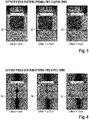
Figure 3 schematically shows an overview of field distributions for the FR2 co-polarization patterns indicating the influence of the offset on the field distributions, and -
Figure 4 schematically shows an overview of field distributions for the FR2 cross-polarization patterns indicating the influence of the offset on the field distributions. - The detailed description set forth below in connection with the appended drawings, where like numerals reference like elements, is intended as a description of various embodiments of the disclosed subject matter and is not intended to represent the only embodiments. Each embodiment described in this disclosure is provided merely as an example or illustration and should not be construed as preferred or advantageous over other embodiments. The illustrative examples provided herein are not intended to be exhaustive or to limit the claimed subject matter to the precise forms disclosed.
- For the purposes of the present disclosure, the phrase "at least one of A, B, and C", for example, means (A), (B), (C), (A and B), (A and C), (B and C), or (A, B, and C), including all further possible permutations when more than three elements are listed. In other words, the term "at least one of A and B" generally means "A and/or B", namely "A" alone, "B" alone or "A and B".
-
Figure 1 shows an over-the-air (OTA)measurement system 10 for testing a device undertest 12. - The
OTA measurement system 10 comprises atesting chamber 14 established by an RF-shielded chamber so as to shield an interior of thechamber 14 from interfering and disturbing signals. In thetesting chamber 14, the device undertest 12 is located at atest location 16. - Moreover, the
OTA measurement system 10 comprisesmeasurement equipment 18 that is used for testing the device undertest 12. In the shown embodiment, themeasurement equipment 18 is connected with atest terminal 20 in order to establish a connection with the device undertest 12 so as to receive signals from the device undertest 12 that can be evaluated by themeasurement equipment 18. - Furthermore, the
measurement equipment 18 is connected with afeed antenna array 22 that comprises a plurality offeed antennas first feed antenna 24 and at least onesecond feed antenna 26, as will be described later in more detail when referring toFigure 2 . - In addition, the
OTA measurement system 10 has areflector array 28 that comprises amain reflector 30 and a sub-reflector 32. - As shown in
Figure 1 , thereflector array 28, particularly itsreflectors testing chamber 14 such that asignal path 34 is established between the plurality offeed antennas test location 16 via the sub-reflector 32 and themain reflector 30. Accordingly, the sub-reflector 32 and themain reflector 30 together relate to a specific dual-reflector system. - In fact, the
feed antennas reflector array 28 such that electromagnetic waves emitted by thefeed antennas main reflector 30 that faces thetest location 16. Accordingly, the electromagnetic waves impinging on themain reflector 30 are reflected towards thetest location 16, thereby establishing aquiet zone 35 at thetest location 16. Hence, the device undertest 12 is located within thequiet zone 35 at thetest location 16, thereby ensuring far-field conditions for testing purposes. - The sub-reflector 32 facing the plurality of
feed antennas focal point 36 indicated by the dotted line inFigure 1 . Accordingly, thefirst feed antenna 24 is associated with the focal point of the sub-reflector 32. In fact, thefirst feed antenna 24 is located exactly at thefocal point 36 or nearby thefocal point 36, namely within unavoidable deviations. In contrast thereto, the at least onesecond feed antenna 26 is located offset from thefocal point 36 of the sub-reflector 32. Specifically, thesecond feed antenna 26 is intentionally located offset from thefocal point 36 to which thefirst feed antenna 24 is assigned. - In the shown embodiment, the sub-reflector 32 is established as a non-paraboloid reflector having a further focal point besides the
focal point 36. Hence, the sub-reflector 32 may have more than one focal point. For instance, the sub-reflector 32 is established by an ellipsoid or a hyperboloid. - In contrast thereto, the
main reflector 30 located between the sub-reflector 32 and thetest location 16 is established as a paraboloid reflector having a single focal point that is associated with thetest location 16. - Accordingly, the
respective antenna array 22 comprising theseveral feed antennas feed antenna arrangement 38 since the at least onesecond feed antenna 26 is (intentionally) located offset from the reflector on which the electromagnetic waves emitted impinge directly, namely the sub-reflector 32. - An embodiment of the
antenna array 22, namely the special offsetfeed antenna arrangement 38, is shown in more detail inFigure 2 . - It becomes obvious that the
antenna array 22 comprises thefirst feed antenna 24 associated with thefocal point 36 of the sub-reflector 22. Particularly, the center of thefirst feed antenna 24 coincides with thefocal point 36. Thefirst feed antenna 24 is configured to emit electromagnetic waves in a first frequency band, namely a frequency band associated with Frequency Range 2 (FR2), e.g. frequencies from 23 GHz up to 53GHz. Particularly, thefirst feed antenna 24 can be used for FR2 in-band testing of the device undertest 12 at frequencies ranging from 23 GHz to 44 GHz. - Furthermore, the
antenna array 22, namely the special offsetfeed antenna arrangement 38, comprises a set ofsecond feed antennas 26 that are distanced from thefocal point 36, e.g. the center of theantenna array 22 or rather the special offsetfeed antenna arrangement 38, by a substantially equal distance labelled by d1. Small deviations from this distance may occur as shown for the lowersecond feed antennas 26 that are also displaced in horizontal direction by a certain distance. - Alternatively, the lower
second feed antennas 26 may be displaced in vertical orientation by a smaller distance than d1 such that allsecond feed antennas 26 are located on a (perfect) circle around thefocal point 36, which has a radius corresponding to distance d1. This is illustrated by the dashed lines inFigure 2 . - Generally, the
second feed antennas 26 together cover a frequency range from 40 GHz to 140 GHz, e.g. one of thesecond feed antennas 26 covers the frequency range from 40 GHz to 60 GHz, anothersecond feed antenna 26 covers the frequency range from 60 GHz to 90 GHz, and a furthersecond feed antenna 26 covers the frequency range from 90 GHz to 140 GHz. - Optionally, a fourth
second feed antenna 26 may be provided that coves a frequency range from 140 GHz to 200 GHz such that allsecond feed antennas 26 cover a frequency range from 40 GHz to 200 GHz. - Accordingly, the at least one
second feed antenna 26, particularly each of thesecond feed antennas 26, is configured to emit electromagnetic waves in a second frequency band that is different from the first frequency band, particularly higher than the first frequency band. Accordingly, a central frequency of the first frequency band is lower than a central frequency of the second frequency band. -
Figure 2 also shows that theantenna array 22, namely the special offsetfeed antenna arrangement 38, has at least onethird feed antenna 40 that is also located offset from thefocal point 36. - A distance between the
focal point 36 and the at least onethird feed antenna 40 is bigger than the distance between thesecond antenna 26 and thefocal point 36. - In the shown embodiment, a set of
third feed antennas 40 is provided, namely three differentthird feed antennas 40 each covering a different frequency range, namely from 6 GHz to 8 GHz, from 8 GHz to 15 GHz and from 15 GHz to 23 GHz. - Alternatively, four
third feed antennas 40 or rather differently designedthird feed antennas 40 may be provided, thereby covering a frequency range from 6 GHz to 40 GHz in total. - For instance, the set of
third feed antennas 40 may comprise a singlethird feed antenna 40 that covers a frequency range from 6 GHz to 40 GHz and twoadditional feed antennas 40 associated with a frequency range from 8 GHz to 15 GHz and from 15 GHz to 23 GHz, respectively. - Accordingly, the at least one
third feed antenna 40 is configured to emit electromagnetic waves in a third frequency band that is different from the first frequency band and from the second frequency band. Particularly, a central frequency of the second frequency band is higher than a central frequency of the third frequency band. Additionally or alternatively, a central frequency of the first frequency band is higher than a central frequency of the third frequency band. Therefore, therespective feed antennas - Accordingly, the
different feed antennas test 12. The frequency bands associated with thedifferent feed antennas - Generally, the plurality of
second feed antennas 26 or ratherthird feed antennas 40 are located offset from thefocal point 36 in a substantially similar manner, e.g. by a similar or rather at least comparable distance, namely within a range of ± 1cm. - In fact, the several
second feed antennas 26 are located on a substantially circular ring around the center of the special offsetfeed antenna arrangement 38. However, the substantially circular ring may have a deviation from a perfect circular ring that amounts to about ± 1cm. Thus, the severalsecond feed antennas 26 are located on a curve enclosing the center of the special offsetfeed antenna arrangement 38 by a substantially similar distance, particularly the same distance with a deviation of about ± 1cm. For instance, the curve associated with thesecond feed antennas 26 has a distance d1 between 3 cm and 4 cm. - The same applies for the several
third feed antennas 40 that are also located on a substantially circular ring around the center of the special offsetfeed antenna arrangement 38. However, the substantially circular ring may have a deviation from a perfect circular ring that amounts to about ± 1cm. Thus, the severalthird feed antennas 40 are located on a curve enclosing the center of the special offsetfeed antenna arrangement 38 by a substantially similar distance, particularly the same distance with a deviation of about ± 1cm. For instance, the curve associated with thethird feed antennas 40 has a distance d2 between 8 cm and 10 cm. - The distance associated with the
second feed antennas 26 is smaller than the distance associated with thethird feed antennas 40. Hence, thesecond feed antennas 26 are located closer to the center of the special offsetfeed antenna arrangement 38 or rather thefocal point 36 than thethird feed antennas 40. - The
second feed antennas 26 are operated at higher frequencies such that their respective apertures are smaller compared to the ones of thethird feed antennas 40 that are operated at lower frequencies. Therefore, thesecond feed antennas 26 are located closer to the center of the special offsetfeed antenna arrangement 38, thereby providing an overallcompact antenna array 22. - Accordingly, the first set of offset feed antennas, namely the
second feed antennas 26, is located closer to the center antenna, namely thefirst feed antenna 24, while operating at higher frequencies (therefore smaller antenna aperture) than the second set of antennas furthest from the center antenna. The second set of antennas furthest from the center antenna correspond to thethird feed antennas 40 that are operated at the lowest frequencies of allfeed antennas antenna array 22. - In
Figure 2 , a table is also shown indicating that the specific offsetfeed antenna arrangement 38 together with thereflector array 28 ensure that a shift of thequiet zone 35 can be neglected compared to systems known in the state of the art since a wavefront of emitted electromagnetic waves is angled by 3.5 degrees in case of an offset of 10°cm for the feed antennas contrary to the prior art resulting in a wavefront angled by 7.4 degrees, requiring a re-positioning of theantenna array 22 and/or the device undertest 12 in order to ensure proper testing conditions. - Accordingly, off-orthogonal angles can be effectively reduced by about 50 % due to the special offset
feed antenna arrangement 38 and thereflector array 28. - This is also illustrated in
Figures 3 and 4 providing overviews of the respective field distributions. - Even though a re-positioning of the device under
test 12 is not necessary due to the small shift of the quiet zone,Figure 1 shows that apositioner 42 for the device undertest 12 is provided. Thepositioner 42 is configured to position the device undertest 12 in a predetermined manner within thetest location 16. In fact, thepositioner 42 can be used for certain test scenarios. - The
OTA measurement system 10 is used for testing the device undertest 12. Accordingly, thedifferent feed antennas test 12 can be tested in a wideband range appropriately. - Certain embodiments disclosed herein, particularly the respective module(s), utilize circuitry (e.g., one or more circuits) in order to implement standards, protocols, methodologies or technologies disclosed herein, operably couple two or more components, generate information, process information, analyze information, generate signals, encode/decode signals, convert signals, transmit and/or receive signals, control other devices, etc. Circuitry of any type can be used.
- In an embodiment, circuitry includes, among other things, one or more computing devices such as a processor (e.g., a microprocessor), a central processing unit (CPU), a digital signal processor (DSP), an application-specific integrated circuit (ASIC), a field-programmable gate array (FPGA), a system on a chip (SoC), or the like, or any combinations thereof, and can include discrete digital or analog circuit elements or electronics, or combinations thereof. In an embodiment, circuitry includes hardware circuit implementations (e.g., implementations in analog circuitry, implementations in digital circuitry, and the like, and combinations thereof).
- In an embodiment, circuitry includes combinations of circuits and computer program products having software or firmware instructions stored on one or more computer readable memories that work together to cause a device to perform one or more protocols, methodologies or technologies described herein. In an embodiment, circuitry includes circuits, such as, for example, microprocessors or portions of microprocessor, that require software, firmware, and the like for operation. In an embodiment, circuitry includes one or more processors or portions thereof and accompanying software, firmware, hardware, and the like.
- The present application may reference quantities and numbers. Unless specifically stated, such quantities and numbers are not to be considered restrictive, but exemplary of the possible quantities or numbers associated with the present application. Also in this regard, the present application may use the term "plurality" to reference a quantity or number. In this regard, the term "plurality" is meant to be any number that is more than one, for example, two, three, four, five, etc. The terms "about", "approximately", "near" etc., mean plus or minus 5% of the stated value.
Claims (15)
- An over-the-air (OTA) measurement system for testing a device under test (12), the OTA measurement system (10) comprising a plurality of feed antennas (24, 26), a test location (16) for the device under test (12), and a reflector array (28) with a main reflector (30) and a sub-reflector (32),the plurality of feed antennas (24, 26) facing the sub-reflector (32),the reflector array (28) being located such that a signal path (34) is established between the plurality of feed antennas (24, 26) and the test location (16) via the sub-reflector (32) and the main reflector (30),the sub-reflector (32) having at least one focal point (36),the plurality of feed antennas (24, 26) comprising a first feed antenna (24) and at least one second feed antenna (26),the first feed antenna (24) being associated with the focal point (36) of the sub-reflector (32), andthe at least one second feed antenna (26(being located offset from the focal point (36) of the sub-reflector (32).
- The OTA measurement system of claim 1, wherein the first feed antenna (24) is configured to emit electromagnetic waves in a first frequency band, and wherein the at least one second feed antenna (26) is configured to emit electromagnetic waves in a second frequency band, the second frequency band being different from the first frequency band, in particular wherein a central frequency of the first frequency band is lower than a central frequency of the second frequency band.
- The OTA measurement system of claim 2, wherein the OTA measurement system (10) comprises at least one third feed antenna (40), the at least one third feed antenna (40) being located offset from the focal point (36), wherein a distance between the focal point (36) and the at least one third feed antenna (40) is bigger than a distance between the second feed antenna (26) and the focal point (36).
- The OTA measurement system of claim 3, wherein the at least one third feed antenna (40) is configured to emit electromagnetic waves in a third frequency band, the third frequency band being different from the first frequency band and from the second frequency band, in particular wherein a central frequency of the second frequency band is higher than a central frequency of the third frequency band and/or wherein a central frequency of the first frequency band is higher than a central frequency of the third frequency band.
- The OTA measurement system of any of the preceding claims, wherein the main reflector (30) is located between the sub-reflector (32) and the test location (16), the main reflector (30) facing the test location (16) and the sub-reflector (32) such that the signal path (34) is established between the plurality of feed antennas (24, 26) and the test location (16) via the sub-reflector (32) and the main reflector (30).
- The OTA measurement system of any of the preceding claims, wherein the sub-reflector (32) facing the plurality of feed antennas (24, 26) is established as a non-paraboloid reflector.
- The OTA measurement system of any of the preceding claims, wherein the main reflector (30) being located between the sub-reflector (32) and the test location (16) is established as a paraboloid reflector.
- The OTA measurement system of any of the preceding claims, the OTA measurement system (10) comprising a positioner (42) for the device under test (12), wherein the positioner (42) is configured to position the device under test (12) in a predetermined manner within the test location (16).
- The OTA measurement system of any of the preceding claims, wherein the OTA measurement system (10) comprises an RF-shielded chamber (14), the RF-shielded chamber (14) enclosing the plurality of feed antennas (24, 26), the test location (16) for the device under test (12), and the reflector array (28), and/or wherein the OTA measurement system (10) comprises measurement equipment (18), the measurement equipment (18) being configured to conduct OTA measurements.
- The OTA measurement system of any of the preceding claims, wherein a quiet zone (35) is established by the plurality of feed antennas (24, 26) together with the reflector array (28), and wherein the test location (16) is located within the quiet zone (35).
- A method of testing a device under test (12) over-the-air, wherein the method comprises the steps of:- providing a device under test (12);- providing an OTA measurement system (10) for testing the device under test (12) over-the-air, wherein the OTA measurement system comprises a plurality of feed antennas (24, 26), a test location (16) for the device under test (12), and a reflector array (28) with a main reflector (30) and a sub-reflector (32), the plurality of feed antennas (24, 26) facing the sub-reflector (32), the reflector array (28) being located such that a signal path (34) is established between the plurality of feed antennas (24, 26) and the test location (16) via the sub-reflector (32) and the main reflector (30), the sub-reflector (32) having at least one focal point (36), the plurality of feed antennas (24, 26) comprising a first feed antenna (24) and at least one second feed antenna (26), the first feed antenna (24) being located at the focal point (36) of the sub-reflector (32), and the at least one second feed antenna (26) being located offset from the focal point (36) of the sub-reflector (32);- placing the device under test (12) at the test location (16); and- performing an over-the-air measurement on the device under test (12).
- The method of claim 11, wherein a first test signal is generated by means of the first feed antenna (24) in a first frequency band, and wherein a second test signal is generated by means of the at least one second feed antenna (26) in a second frequency band, the second frequency band being different from the first frequency band.
- The method of claim 12, wherein a central frequency of the first frequency band is lower than a central frequency of the second frequency band.
- The method of claim 12 or 13, wherein the OTA measurement system (10) comprises at least one third feed antenna (40), the at least one third feed antenna (40) being located offset from the focal point (36), wherein a distance between the focal point (36) and the at least one third feed antenna (40) is bigger than a distance between the second feed antenna (26) and the focal point (36), and wherein a third test signal is generated by means of the at least one third feed antenna (40) in a third frequency band, the third frequency band being different from the first frequency band and from the second frequency band, in particular wherein a central frequency of the second frequency band is higher than a central frequency of the third frequency band and/or wherein a central frequency of the first frequency band is higher than a central frequency of the third frequency band.
- The method of any of claims 11 to 14, wherein the main reflector (30) is located between the sub-reflector (32) and the test location (16), the main reflector (30) facing the test location (16) and the sub-reflector (32) such that the signal path (34) is established between the plurality of feed antennas (24, 26) and the test location (16) via the sub-reflector (32) and the main reflector (30).
Applications Claiming Priority (1)
| Application Number | Priority Date | Filing Date | Title |
|---|---|---|---|
| US17/157,711 US11782082B2 (en) | 2021-01-25 | 2021-01-25 | Over-the-air measurement system and method of testing a device under test over-the-air |
Publications (2)
| Publication Number | Publication Date |
|---|---|
| EP4033260A1 true EP4033260A1 (en) | 2022-07-27 |
| EP4033260B1 EP4033260B1 (en) | 2024-08-21 |
Family
ID=78414379
Family Applications (1)
| Application Number | Title | Priority Date | Filing Date |
|---|---|---|---|
| EP21205302.9A Active EP4033260B1 (en) | 2021-01-25 | 2021-10-28 | Over-the-air measurement system and method of testing a device under test over-the-air |
Country Status (2)
| Country | Link |
|---|---|
| US (1) | US11782082B2 (en) |
| EP (1) | EP4033260B1 (en) |
Families Citing this family (1)
| Publication number | Priority date | Publication date | Assignee | Title |
|---|---|---|---|---|
| EP4092429B1 (en) * | 2021-05-21 | 2024-10-23 | Rohde & Schwarz GmbH & Co. KG | Test system |
Citations (3)
| Publication number | Priority date | Publication date | Assignee | Title |
|---|---|---|---|---|
| US20100109932A1 (en) * | 2008-10-24 | 2010-05-06 | Kefeng Liu | Termination of edges of a parabolic reflector in a compact range |
| US20190199002A1 (en) * | 2017-12-22 | 2019-06-27 | Rohde & Schwarz Gmbh & Co. Kg | Measurement system and method comprising a compact antenna range reflector |
| US20200217885A1 (en) * | 2019-01-03 | 2020-07-09 | Rohde & Schwarz Gmbh & Co. Kg | Measurement system and method for multiple antenna measurements with different angles of arrival |
Family Cites Families (8)
| Publication number | Priority date | Publication date | Assignee | Title |
|---|---|---|---|---|
| EP0221181A1 (en) * | 1985-05-01 | 1987-05-13 | Harris Corporation | Compact antenna range employing shaped reflectors |
| US20140313080A1 (en) | 2013-04-19 | 2014-10-23 | Telefonaktiebolaget L M Ericsson | Multi-beam smart antenna for wylan and pico cellular applications |
| US11750303B2 (en) * | 2016-06-30 | 2023-09-05 | Keysight Technologies, Inc. | Compact system for characterizing a device under test (DUT) having integrated antenna array |
| DE102017122443A1 (en) * | 2017-09-27 | 2019-03-28 | Rohde & Schwarz Gmbh & Co. Kg | Test system for calibrating an antenna test system, method for calibrating an antenna test system and method for determining the passive intermodulation characteristic of a test object |
| US10536228B2 (en) * | 2018-01-11 | 2020-01-14 | Rohde & Schwarz Gmbh & Co. Kg | Test system and test method |
| JP6886449B2 (en) * | 2018-11-29 | 2021-06-16 | アンリツ株式会社 | Antenna device and measurement method |
| EP3828558B1 (en) * | 2019-11-29 | 2023-07-26 | Rohde & Schwarz GmbH & Co. KG | Over the air measuring device with feed switcher positioner |
| WO2021204949A1 (en) * | 2020-04-09 | 2021-10-14 | Fraunhofer-Gesellschaft zur Förderung der angewandten Forschung e.V. | Determining beam correspondence parameters |
-
2021
- 2021-01-25 US US17/157,711 patent/US11782082B2/en active Active
- 2021-10-28 EP EP21205302.9A patent/EP4033260B1/en active Active
Patent Citations (3)
| Publication number | Priority date | Publication date | Assignee | Title |
|---|---|---|---|---|
| US20100109932A1 (en) * | 2008-10-24 | 2010-05-06 | Kefeng Liu | Termination of edges of a parabolic reflector in a compact range |
| US20190199002A1 (en) * | 2017-12-22 | 2019-06-27 | Rohde & Schwarz Gmbh & Co. Kg | Measurement system and method comprising a compact antenna range reflector |
| US20200217885A1 (en) * | 2019-01-03 | 2020-07-09 | Rohde & Schwarz Gmbh & Co. Kg | Measurement system and method for multiple antenna measurements with different angles of arrival |
Non-Patent Citations (1)
| Title |
|---|
| ROWELL CORBETT ET AL: "Multiple CATR Reflector System for Multiple Angles of Arrival Measurements of 5G Millimeter Wave Devices", IEEE ACCESS, IEEE, USA, vol. 8, 16 November 2020 (2020-11-16), pages 211324 - 211334, XP011823079, DOI: 10.1109/ACCESS.2020.3038597 * |
Also Published As
| Publication number | Publication date |
|---|---|
| EP4033260B1 (en) | 2024-08-21 |
| US20220236310A1 (en) | 2022-07-28 |
| US11782082B2 (en) | 2023-10-10 |
Similar Documents
| Publication | Publication Date | Title |
|---|---|---|
| US11397205B2 (en) | Measurement system and method of performing an over-the-air test | |
| US10670644B2 (en) | Beamforming of harmonics | |
| CN112688052B (en) | Common-aperture antenna and communication equipment | |
| US10686540B2 (en) | Anechoic test chamber, test system and test method for testing the antennas of a device under test | |
| US6104935A (en) | Down link beam forming architecture for heavily overlapped beam configuration | |
| US20130234911A1 (en) | Mobile communication terminal with improved isolation | |
| US10116425B2 (en) | Diplexed antenna with semi-independent tilt | |
| EP2192707A1 (en) | Method of calibrating an active antenna and active antenna | |
| CN120432870A (en) | Antenna system and base station antenna feed system | |
| EP2912719A1 (en) | Reflector arrangement for attachment to a wireless communications terminal | |
| EP4033260B1 (en) | Over-the-air measurement system and method of testing a device under test over-the-air | |
| US11340278B2 (en) | Measurement system for testing a device under test over-the-air | |
| CN110224232A (en) | For reducing the antenna system and method for the signal radiation being not intended on direction | |
| US9923278B2 (en) | Diversity antenna arrangement for WLAN, and WLAN communication unit having such a diversity antenna arrangement, and device having such a WLAN communication unit | |
| US11177559B2 (en) | Radiator assembly for base station antenna | |
| EP4174499B1 (en) | Over-the-air measurement system | |
| Demirci et al. | Phase error analysis of displaced-axis dual reflector antenna for satellite earth stations | |
| US11848507B2 (en) | Radiating element, antenna array, and network device | |
| Moongilan | EIRP, TRP, Partial TRP and Radiated Immunity For 5G millimeter Wave Device Compliance | |
| US11835559B2 (en) | Over-the-air test system and method of performing an over-the-air measurement | |
| JP7382430B2 (en) | Antenna device and performance test method | |
| JP4689503B2 (en) | Antenna device | |
| CN104617387A (en) | Composite antenna of VHF waveband and X waveband | |
| HK40012775B (en) | Beamforming of harmonics | |
| KR19990056550A (en) | Antenna installation method when interference between adjacent frequencies |
Legal Events
| Date | Code | Title | Description |
|---|---|---|---|
| PUAI | Public reference made under article 153(3) epc to a published international application that has entered the european phase |
Free format text: ORIGINAL CODE: 0009012 |
|
| STAA | Information on the status of an ep patent application or granted ep patent |
Free format text: STATUS: THE APPLICATION HAS BEEN PUBLISHED |
|
| AK | Designated contracting states |
Kind code of ref document: A1 Designated state(s): AL AT BE BG CH CY CZ DE DK EE ES FI FR GB GR HR HU IE IS IT LI LT LU LV MC MK MT NL NO PL PT RO RS SE SI SK SM TR |
|
| STAA | Information on the status of an ep patent application or granted ep patent |
Free format text: STATUS: REQUEST FOR EXAMINATION WAS MADE |
|
| 17P | Request for examination filed |
Effective date: 20221212 |
|
| RBV | Designated contracting states (corrected) |
Designated state(s): AL AT BE BG CH CY CZ DE DK EE ES FI FR GB GR HR HU IE IS IT LI LT LU LV MC MK MT NL NO PL PT RO RS SE SI SK SM TR |
|
| P01 | Opt-out of the competence of the unified patent court (upc) registered |
Effective date: 20230525 |
|
| GRAP | Despatch of communication of intention to grant a patent |
Free format text: ORIGINAL CODE: EPIDOSNIGR1 |
|
| STAA | Information on the status of an ep patent application or granted ep patent |
Free format text: STATUS: GRANT OF PATENT IS INTENDED |
|
| INTG | Intention to grant announced |
Effective date: 20240508 |
|
| GRAS | Grant fee paid |
Free format text: ORIGINAL CODE: EPIDOSNIGR3 |
|
| GRAA | (expected) grant |
Free format text: ORIGINAL CODE: 0009210 |
|
| STAA | Information on the status of an ep patent application or granted ep patent |
Free format text: STATUS: THE PATENT HAS BEEN GRANTED |
|
| RBV | Designated contracting states (corrected) |
Designated state(s): AL AT BE BG CY CZ DE DK EE ES FI FR GB GR HR HU IS IT LT LU LV MC MK MT NL NO PL PT RO RS SE SI SK SM TR |
|
| AK | Designated contracting states |
Kind code of ref document: B1 Designated state(s): AL AT BE BG CY CZ DE DK EE ES FI FR GB GR HR HU IS IT LT LU LV MC MK MT NL NO PL PT RO RS SE SI SK SM TR |
|
| REG | Reference to a national code |
Ref country code: GB Ref legal event code: FG4D |
|
| REG | Reference to a national code |
Ref country code: DE Ref legal event code: R096 Ref document number: 602021017455 Country of ref document: DE |
|
| REG | Reference to a national code |
Ref country code: LT Ref legal event code: MG9D |
|
| REG | Reference to a national code |
Ref country code: NL Ref legal event code: MP Effective date: 20240821 |
|
| PG25 | Lapsed in a contracting state [announced via postgrant information from national office to epo] |
Ref country code: NO Free format text: LAPSE BECAUSE OF FAILURE TO SUBMIT A TRANSLATION OF THE DESCRIPTION OR TO PAY THE FEE WITHIN THE PRESCRIBED TIME-LIMIT Effective date: 20241121 |
|
| REG | Reference to a national code |
Ref country code: AT Ref legal event code: MK05 Ref document number: 1715995 Country of ref document: AT Kind code of ref document: T Effective date: 20240821 |
|
| PG25 | Lapsed in a contracting state [announced via postgrant information from national office to epo] |
Ref country code: PT Free format text: LAPSE BECAUSE OF FAILURE TO SUBMIT A TRANSLATION OF THE DESCRIPTION OR TO PAY THE FEE WITHIN THE PRESCRIBED TIME-LIMIT Effective date: 20241223 Ref country code: NL Free format text: LAPSE BECAUSE OF FAILURE TO SUBMIT A TRANSLATION OF THE DESCRIPTION OR TO PAY THE FEE WITHIN THE PRESCRIBED TIME-LIMIT Effective date: 20240821 Ref country code: FI Free format text: LAPSE BECAUSE OF FAILURE TO SUBMIT A TRANSLATION OF THE DESCRIPTION OR TO PAY THE FEE WITHIN THE PRESCRIBED TIME-LIMIT Effective date: 20240821 Ref country code: PL Free format text: LAPSE BECAUSE OF FAILURE TO SUBMIT A TRANSLATION OF THE DESCRIPTION OR TO PAY THE FEE WITHIN THE PRESCRIBED TIME-LIMIT Effective date: 20240821 Ref country code: GR Free format text: LAPSE BECAUSE OF FAILURE TO SUBMIT A TRANSLATION OF THE DESCRIPTION OR TO PAY THE FEE WITHIN THE PRESCRIBED TIME-LIMIT Effective date: 20241122 |
|
| PG25 | Lapsed in a contracting state [announced via postgrant information from national office to epo] |
Ref country code: BG Free format text: LAPSE BECAUSE OF FAILURE TO SUBMIT A TRANSLATION OF THE DESCRIPTION OR TO PAY THE FEE WITHIN THE PRESCRIBED TIME-LIMIT Effective date: 20240821 |
|
| PG25 | Lapsed in a contracting state [announced via postgrant information from national office to epo] |
Ref country code: LV Free format text: LAPSE BECAUSE OF FAILURE TO SUBMIT A TRANSLATION OF THE DESCRIPTION OR TO PAY THE FEE WITHIN THE PRESCRIBED TIME-LIMIT Effective date: 20240821 |
|
| PG25 | Lapsed in a contracting state [announced via postgrant information from national office to epo] |
Ref country code: AT Free format text: LAPSE BECAUSE OF FAILURE TO SUBMIT A TRANSLATION OF THE DESCRIPTION OR TO PAY THE FEE WITHIN THE PRESCRIBED TIME-LIMIT Effective date: 20240821 Ref country code: IS Free format text: LAPSE BECAUSE OF FAILURE TO SUBMIT A TRANSLATION OF THE DESCRIPTION OR TO PAY THE FEE WITHIN THE PRESCRIBED TIME-LIMIT Effective date: 20241221 |
|
| PG25 | Lapsed in a contracting state [announced via postgrant information from national office to epo] |
Ref country code: HR Free format text: LAPSE BECAUSE OF FAILURE TO SUBMIT A TRANSLATION OF THE DESCRIPTION OR TO PAY THE FEE WITHIN THE PRESCRIBED TIME-LIMIT Effective date: 20240821 |
|
| PG25 | Lapsed in a contracting state [announced via postgrant information from national office to epo] |
Ref country code: RS Free format text: LAPSE BECAUSE OF FAILURE TO SUBMIT A TRANSLATION OF THE DESCRIPTION OR TO PAY THE FEE WITHIN THE PRESCRIBED TIME-LIMIT Effective date: 20241121 Ref country code: ES Free format text: LAPSE BECAUSE OF FAILURE TO SUBMIT A TRANSLATION OF THE DESCRIPTION OR TO PAY THE FEE WITHIN THE PRESCRIBED TIME-LIMIT Effective date: 20240821 |
|
| PG25 | Lapsed in a contracting state [announced via postgrant information from national office to epo] |
Ref country code: RS Free format text: LAPSE BECAUSE OF FAILURE TO SUBMIT A TRANSLATION OF THE DESCRIPTION OR TO PAY THE FEE WITHIN THE PRESCRIBED TIME-LIMIT Effective date: 20241121 Ref country code: PT Free format text: LAPSE BECAUSE OF FAILURE TO SUBMIT A TRANSLATION OF THE DESCRIPTION OR TO PAY THE FEE WITHIN THE PRESCRIBED TIME-LIMIT Effective date: 20241223 Ref country code: PL Free format text: LAPSE BECAUSE OF FAILURE TO SUBMIT A TRANSLATION OF THE DESCRIPTION OR TO PAY THE FEE WITHIN THE PRESCRIBED TIME-LIMIT Effective date: 20240821 Ref country code: NO Free format text: LAPSE BECAUSE OF FAILURE TO SUBMIT A TRANSLATION OF THE DESCRIPTION OR TO PAY THE FEE WITHIN THE PRESCRIBED TIME-LIMIT Effective date: 20241121 Ref country code: NL Free format text: LAPSE BECAUSE OF FAILURE TO SUBMIT A TRANSLATION OF THE DESCRIPTION OR TO PAY THE FEE WITHIN THE PRESCRIBED TIME-LIMIT Effective date: 20240821 Ref country code: LV Free format text: LAPSE BECAUSE OF FAILURE TO SUBMIT A TRANSLATION OF THE DESCRIPTION OR TO PAY THE FEE WITHIN THE PRESCRIBED TIME-LIMIT Effective date: 20240821 Ref country code: IS Free format text: LAPSE BECAUSE OF FAILURE TO SUBMIT A TRANSLATION OF THE DESCRIPTION OR TO PAY THE FEE WITHIN THE PRESCRIBED TIME-LIMIT Effective date: 20241221 Ref country code: HR Free format text: LAPSE BECAUSE OF FAILURE TO SUBMIT A TRANSLATION OF THE DESCRIPTION OR TO PAY THE FEE WITHIN THE PRESCRIBED TIME-LIMIT Effective date: 20240821 Ref country code: GR Free format text: LAPSE BECAUSE OF FAILURE TO SUBMIT A TRANSLATION OF THE DESCRIPTION OR TO PAY THE FEE WITHIN THE PRESCRIBED TIME-LIMIT Effective date: 20241122 Ref country code: FI Free format text: LAPSE BECAUSE OF FAILURE TO SUBMIT A TRANSLATION OF THE DESCRIPTION OR TO PAY THE FEE WITHIN THE PRESCRIBED TIME-LIMIT Effective date: 20240821 Ref country code: ES Free format text: LAPSE BECAUSE OF FAILURE TO SUBMIT A TRANSLATION OF THE DESCRIPTION OR TO PAY THE FEE WITHIN THE PRESCRIBED TIME-LIMIT Effective date: 20240821 Ref country code: BG Free format text: LAPSE BECAUSE OF FAILURE TO SUBMIT A TRANSLATION OF THE DESCRIPTION OR TO PAY THE FEE WITHIN THE PRESCRIBED TIME-LIMIT Effective date: 20240821 Ref country code: AT Free format text: LAPSE BECAUSE OF FAILURE TO SUBMIT A TRANSLATION OF THE DESCRIPTION OR TO PAY THE FEE WITHIN THE PRESCRIBED TIME-LIMIT Effective date: 20240821 |
|
| PG25 | Lapsed in a contracting state [announced via postgrant information from national office to epo] |
Ref country code: DK Free format text: LAPSE BECAUSE OF FAILURE TO SUBMIT A TRANSLATION OF THE DESCRIPTION OR TO PAY THE FEE WITHIN THE PRESCRIBED TIME-LIMIT Effective date: 20240821 Ref country code: SM Free format text: LAPSE BECAUSE OF FAILURE TO SUBMIT A TRANSLATION OF THE DESCRIPTION OR TO PAY THE FEE WITHIN THE PRESCRIBED TIME-LIMIT Effective date: 20240821 Ref country code: RO Free format text: LAPSE BECAUSE OF FAILURE TO SUBMIT A TRANSLATION OF THE DESCRIPTION OR TO PAY THE FEE WITHIN THE PRESCRIBED TIME-LIMIT Effective date: 20240821 |
|
| PG25 | Lapsed in a contracting state [announced via postgrant information from national office to epo] |
Ref country code: EE Free format text: LAPSE BECAUSE OF FAILURE TO SUBMIT A TRANSLATION OF THE DESCRIPTION OR TO PAY THE FEE WITHIN THE PRESCRIBED TIME-LIMIT Effective date: 20240821 |
|
| PG25 | Lapsed in a contracting state [announced via postgrant information from national office to epo] |
Ref country code: CZ Free format text: LAPSE BECAUSE OF FAILURE TO SUBMIT A TRANSLATION OF THE DESCRIPTION OR TO PAY THE FEE WITHIN THE PRESCRIBED TIME-LIMIT Effective date: 20240821 |
|
| PG25 | Lapsed in a contracting state [announced via postgrant information from national office to epo] |
Ref country code: SK Free format text: LAPSE BECAUSE OF FAILURE TO SUBMIT A TRANSLATION OF THE DESCRIPTION OR TO PAY THE FEE WITHIN THE PRESCRIBED TIME-LIMIT Effective date: 20240821 Ref country code: IT Free format text: LAPSE BECAUSE OF FAILURE TO SUBMIT A TRANSLATION OF THE DESCRIPTION OR TO PAY THE FEE WITHIN THE PRESCRIBED TIME-LIMIT Effective date: 20240821 |
|
| REG | Reference to a national code |
Ref country code: DE Ref legal event code: R097 Ref document number: 602021017455 Country of ref document: DE |
|
| PLBE | No opposition filed within time limit |
Free format text: ORIGINAL CODE: 0009261 |
|
| STAA | Information on the status of an ep patent application or granted ep patent |
Free format text: STATUS: NO OPPOSITION FILED WITHIN TIME LIMIT |
|
| PG25 | Lapsed in a contracting state [announced via postgrant information from national office to epo] |
Ref country code: MC Free format text: LAPSE BECAUSE OF FAILURE TO SUBMIT A TRANSLATION OF THE DESCRIPTION OR TO PAY THE FEE WITHIN THE PRESCRIBED TIME-LIMIT Effective date: 20240821 |
|
| PG25 | Lapsed in a contracting state [announced via postgrant information from national office to epo] |
Ref country code: BE Free format text: LAPSE BECAUSE OF NON-PAYMENT OF DUE FEES Effective date: 20241031 Ref country code: LU Free format text: LAPSE BECAUSE OF NON-PAYMENT OF DUE FEES Effective date: 20241028 |
|
| 26N | No opposition filed |
Effective date: 20250522 |
|
| REG | Reference to a national code |
Ref country code: BE Ref legal event code: MM Effective date: 20241031 |
|
| PG25 | Lapsed in a contracting state [announced via postgrant information from national office to epo] |
Ref country code: SE Free format text: LAPSE BECAUSE OF FAILURE TO SUBMIT A TRANSLATION OF THE DESCRIPTION OR TO PAY THE FEE WITHIN THE PRESCRIBED TIME-LIMIT Effective date: 20240821 |
|
| PGFP | Annual fee paid to national office [announced via postgrant information from national office to epo] |
Ref country code: DE Payment date: 20251020 Year of fee payment: 5 |
|
| PGFP | Annual fee paid to national office [announced via postgrant information from national office to epo] |
Ref country code: GB Payment date: 20251024 Year of fee payment: 5 |
|
| PGFP | Annual fee paid to national office [announced via postgrant information from national office to epo] |
Ref country code: FR Payment date: 20251027 Year of fee payment: 5 |
|
| PG25 | Lapsed in a contracting state [announced via postgrant information from national office to epo] |
Ref country code: HU Free format text: LAPSE BECAUSE OF FAILURE TO SUBMIT A TRANSLATION OF THE DESCRIPTION OR TO PAY THE FEE WITHIN THE PRESCRIBED TIME-LIMIT; INVALID AB INITIO Effective date: 20211028 |
|
| PG25 | Lapsed in a contracting state [announced via postgrant information from national office to epo] |
Ref country code: CY Free format text: LAPSE BECAUSE OF FAILURE TO SUBMIT A TRANSLATION OF THE DESCRIPTION OR TO PAY THE FEE WITHIN THE PRESCRIBED TIME-LIMIT; INVALID AB INITIO Effective date: 20211028 |
|
| PG25 | Lapsed in a contracting state [announced via postgrant information from national office to epo] |
Ref country code: TR Free format text: LAPSE BECAUSE OF FAILURE TO SUBMIT A TRANSLATION OF THE DESCRIPTION OR TO PAY THE FEE WITHIN THE PRESCRIBED TIME-LIMIT Effective date: 20240821 |
|
| PG25 | Lapsed in a contracting state [announced via postgrant information from national office to epo] |
Ref country code: SI Free format text: LAPSE BECAUSE OF FAILURE TO SUBMIT A TRANSLATION OF THE DESCRIPTION OR TO PAY THE FEE WITHIN THE PRESCRIBED TIME-LIMIT Effective date: 20240821 |
|
| PG25 | Lapsed in a contracting state [announced via postgrant information from national office to epo] |
Ref country code: LT Free format text: LAPSE BECAUSE OF FAILURE TO SUBMIT A TRANSLATION OF THE DESCRIPTION OR TO PAY THE FEE WITHIN THE PRESCRIBED TIME-LIMIT Effective date: 20240821 |