EP4033230A1 - Method of detecting material in a part - Google Patents
Method of detecting material in a part Download PDFInfo
- Publication number
- EP4033230A1 EP4033230A1 EP22162564.3A EP22162564A EP4033230A1 EP 4033230 A1 EP4033230 A1 EP 4033230A1 EP 22162564 A EP22162564 A EP 22162564A EP 4033230 A1 EP4033230 A1 EP 4033230A1
- Authority
- EP
- European Patent Office
- Prior art keywords
- ray image
- image
- matter
- ray
- producing
- Prior art date
- Legal status (The legal status is an assumption and is not a legal conclusion. Google has not performed a legal analysis and makes no representation as to the accuracy of the status listed.)
- Withdrawn
Links
Images

Classifications
-
- G—PHYSICS
- G01—MEASURING; TESTING
- G01N—INVESTIGATING OR ANALYSING MATERIALS BY DETERMINING THEIR CHEMICAL OR PHYSICAL PROPERTIES
- G01N23/00—Investigating or analysing materials by the use of wave or particle radiation, e.g. X-rays or neutrons, not covered by groups G01N3/00 – G01N17/00, G01N21/00 or G01N22/00
- G01N23/02—Investigating or analysing materials by the use of wave or particle radiation, e.g. X-rays or neutrons, not covered by groups G01N3/00 – G01N17/00, G01N21/00 or G01N22/00 by transmitting the radiation through the material
- G01N23/04—Investigating or analysing materials by the use of wave or particle radiation, e.g. X-rays or neutrons, not covered by groups G01N3/00 – G01N17/00, G01N21/00 or G01N22/00 by transmitting the radiation through the material and forming images of the material
-
- G—PHYSICS
- G01—MEASURING; TESTING
- G01N—INVESTIGATING OR ANALYSING MATERIALS BY DETERMINING THEIR CHEMICAL OR PHYSICAL PROPERTIES
- G01N23/00—Investigating or analysing materials by the use of wave or particle radiation, e.g. X-rays or neutrons, not covered by groups G01N3/00 – G01N17/00, G01N21/00 or G01N22/00
- G01N23/02—Investigating or analysing materials by the use of wave or particle radiation, e.g. X-rays or neutrons, not covered by groups G01N3/00 – G01N17/00, G01N21/00 or G01N22/00 by transmitting the radiation through the material
- G01N23/06—Investigating or analysing materials by the use of wave or particle radiation, e.g. X-rays or neutrons, not covered by groups G01N3/00 – G01N17/00, G01N21/00 or G01N22/00 by transmitting the radiation through the material and measuring the absorption
- G01N23/083—Investigating or analysing materials by the use of wave or particle radiation, e.g. X-rays or neutrons, not covered by groups G01N3/00 – G01N17/00, G01N21/00 or G01N22/00 by transmitting the radiation through the material and measuring the absorption the radiation being X-rays
-
- G—PHYSICS
- G01—MEASURING; TESTING
- G01N—INVESTIGATING OR ANALYSING MATERIALS BY DETERMINING THEIR CHEMICAL OR PHYSICAL PROPERTIES
- G01N23/00—Investigating or analysing materials by the use of wave or particle radiation, e.g. X-rays or neutrons, not covered by groups G01N3/00 – G01N17/00, G01N21/00 or G01N22/00
- G01N23/02—Investigating or analysing materials by the use of wave or particle radiation, e.g. X-rays or neutrons, not covered by groups G01N3/00 – G01N17/00, G01N21/00 or G01N22/00 by transmitting the radiation through the material
- G01N23/06—Investigating or analysing materials by the use of wave or particle radiation, e.g. X-rays or neutrons, not covered by groups G01N3/00 – G01N17/00, G01N21/00 or G01N22/00 by transmitting the radiation through the material and measuring the absorption
- G01N23/083—Investigating or analysing materials by the use of wave or particle radiation, e.g. X-rays or neutrons, not covered by groups G01N3/00 – G01N17/00, G01N21/00 or G01N22/00 by transmitting the radiation through the material and measuring the absorption the radiation being X-rays
- G01N23/087—Investigating or analysing materials by the use of wave or particle radiation, e.g. X-rays or neutrons, not covered by groups G01N3/00 – G01N17/00, G01N21/00 or G01N22/00 by transmitting the radiation through the material and measuring the absorption the radiation being X-rays using polyenergetic X-rays
-
- G—PHYSICS
- G01—MEASURING; TESTING
- G01N—INVESTIGATING OR ANALYSING MATERIALS BY DETERMINING THEIR CHEMICAL OR PHYSICAL PROPERTIES
- G01N23/00—Investigating or analysing materials by the use of wave or particle radiation, e.g. X-rays or neutrons, not covered by groups G01N3/00 – G01N17/00, G01N21/00 or G01N22/00
- G01N23/02—Investigating or analysing materials by the use of wave or particle radiation, e.g. X-rays or neutrons, not covered by groups G01N3/00 – G01N17/00, G01N21/00 or G01N22/00 by transmitting the radiation through the material
- G01N23/06—Investigating or analysing materials by the use of wave or particle radiation, e.g. X-rays or neutrons, not covered by groups G01N3/00 – G01N17/00, G01N21/00 or G01N22/00 by transmitting the radiation through the material and measuring the absorption
- G01N23/18—Investigating the presence of flaws defects or foreign matter
-
- G—PHYSICS
- G01—MEASURING; TESTING
- G01N—INVESTIGATING OR ANALYSING MATERIALS BY DETERMINING THEIR CHEMICAL OR PHYSICAL PROPERTIES
- G01N2223/00—Investigating materials by wave or particle radiation
- G01N2223/40—Imaging
- G01N2223/41—Imaging imaging specifically internal structure
-
- G—PHYSICS
- G01—MEASURING; TESTING
- G01N—INVESTIGATING OR ANALYSING MATERIALS BY DETERMINING THEIR CHEMICAL OR PHYSICAL PROPERTIES
- G01N2223/00—Investigating materials by wave or particle radiation
- G01N2223/40—Imaging
- G01N2223/423—Imaging multispectral imaging-multiple energy imaging
-
- G—PHYSICS
- G01—MEASURING; TESTING
- G01N—INVESTIGATING OR ANALYSING MATERIALS BY DETERMINING THEIR CHEMICAL OR PHYSICAL PROPERTIES
- G01N2223/00—Investigating materials by wave or particle radiation
- G01N2223/40—Imaging
- G01N2223/424—Imaging energy substraction image processing (dual energy processing)
-
- G—PHYSICS
- G01—MEASURING; TESTING
- G01N—INVESTIGATING OR ANALYSING MATERIALS BY DETERMINING THEIR CHEMICAL OR PHYSICAL PROPERTIES
- G01N2223/00—Investigating materials by wave or particle radiation
- G01N2223/60—Specific applications or type of materials
- G01N2223/63—Specific applications or type of materials turbine blades
-
- G—PHYSICS
- G01—MEASURING; TESTING
- G01N—INVESTIGATING OR ANALYSING MATERIALS BY DETERMINING THEIR CHEMICAL OR PHYSICAL PROPERTIES
- G01N2223/00—Investigating materials by wave or particle radiation
- G01N2223/60—Specific applications or type of materials
- G01N2223/652—Specific applications or type of materials impurities, foreign matter, trace amounts
Definitions
- Detection of materials that are present within another material using x-rays is particularly difficult if the surrounding material has a significantly higher x-ray absorption characteristic. For such cases, higher x-ray energies are required to penetrate and evaluate the surrounding material which can make the materials with low absorption characteristics essentially invisible in the resulting x-ray image.
- An example of such a case is the detection of casting core material within the metal structure of aerospace components. While the core material is intended to be completely removed before part usage, a costly neutron radiographic procedure is typically invoked to detect residual core material that would be detrimental to the part if left in the part.
- An exemplary method disclosed herein includes the steps of producing a first digital x-ray image of a part utilizing a full x-ray spectrum, producing a second digital x-ray image of the part utilizing a higher energy portion of the full spectrum, subtracting the second x-ray image from the first x-ray image, and using a remainder of the subtracting step to locate certain matter.
- the method includes creating a first digital x-ray image of the part.
- the method includes creating a second digital x-ray image of the part.
- the method includes creating a third digital x-ray image of the part.
- the method includes enhancing the remainder for detection by a user or through automated algorithms, of the matter.
- the method includes creating an image of the remainder in which the matter is displayed.
- the method includes a limitation wherein the part is in a same position during the x-raying steps.
- a further exemplary method disclosed herein includes the steps of producing a first digital x-ray image of a blade utilizing a full x-ray spectrum, producing a second digital x-ray image of the blade with a hardened beam correlating to an upper portion of the full spectrum, subtracting the second x-ray image from the first x-ray image, and using a remainder of the subtracting step to locate matter.
- the method includes the limitation the full spectrum is between 60-650 Kv.
- the method includes the limitation wherein the hardened beam is between 300-650 Kv.
- the producing a first x-ray step includes creating a first image of the x-rayed part
- the producing a second x-ray step includes creating a second image of the x-rayed part
- the subtraction step includes creating a third image of the x-rayed part.
- the method includes enhancing the remainder for detection by a user or through automated algorithms, of the matter.
- the method includes creating an image of the remainder in which the matter is displayed.
- the method includes a limitation wherein the part is in a same position during the x-raying steps.
- a still further exemplary method disclosed herein includes the steps of producing a first digital x-ray image of a blade across a full spectrum, producing a second x-ray of the blade with a hardened beam correlating to an upper portion of the full spectrum, subtracting the second x-ray from the first digital x-ray image, and using a remainder of the subtracting step to locate matter.
- the method includes a limitation wherein the full spectrum is between 60-650 Kv and a hardened beam is between 300-650 Kv.
- the method includes enhancing the remainder for detection by a user or through automated algorithms, of the matter.
- the method includes a limitation wherein the producing a first x-ray step includes creating a first digital image of the x-rayed part, the producing a second x-ray step includes creating a second digital image of the x-rayed part and the subtraction step includes creating a third digital image of the x-rayed part.
- an x-ray system 5 includes an x-ray source 10, as is known in the art, a part (such as a blade 15) to be x-rayed and a digital x-ray detector 20.
- the x-ray detector 20 is connected to a general purpose computer 25 which receives information from the digital x-ray detector 20.
- the x-ray source is driven by a controller 29.
- the blade 15 may be used in the turbine environment in a gas turbine engine (not shown).
- the blade 15 has an airfoil 40, a base 45, a platform 50 and an air passage 55.
- a first image 60 of an x-ray of the blade 15 is displayed including its airfoil 40, base 45, platform 50 and the air passage 55.
- the blade 15 may be made as noted above of titanium or nickel alloys or the like.
- the blade 15 shown herein is made of a nickel alloy.
- Figure 2A shows a first image 60 created in a first plurality of pixels (not shown) in which the x-ray source 10 bombards the blade 15 with a full spectrum of energy between 60 and 650 kilovolts ("Kv") as shown in graph 37.
- the data that is recorded at the detector reflects the absorption characteristics of the unwanted material as well as the parent material of the blade 15.
- the resultant image is overwhelmed by the highly attenuative parent material. For instance, one can see the main elements of the blade 15 including the airfoil 40, the base 45, the platform 50 and the air passage 55.
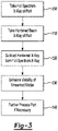
- the first image 60 forms a first part 100 (see Figure 3 ) of the process.
- One of ordinary skill in the art will recognize that other full spectrum energy levels may be required for different materials, or for thicker or thinner portions of other parts 15.
- Such material or defect 65 may also be disposed in the blade 15 and may include dross or other low density particles, porosity, micro-shrinkage, grain boundary separation, or the like.
- a hardened beam e.g., a spectrum between 300 to 650 Kv or a higher range of the full spectrum of energy - see graph 71
- second image 75 is shown of the structure of the blade 15, including the airfoil 40, the base 45, the platform 50 and the air passage 55.
- other hardened beams having different ranges of energy may be required to be used for different materials, or for thicker or thinner portions of other parts 15.
- the first image 60 and the second image 75 is taken while the part 15 is in the same position. There are no registration issues of the two images 60, 75 thereby.
- a third image 80 (see Fig. 2C ) is created to allow the material 65 to be seen.
- the second image 75 is subtracted from the first image 60 on a pixel-by-pixel basis within the general purpose computer 25.
- the pixels that display in figure 2C are essentially the remainder of the subtraction step 120.
- the spectrum shown relates to the energy in the 60-300 Kv range.
- the computer processes the third image 80 to enhance an image 90 of the matter 65 by using an automated algorithm 95 as is known in the art residing in general purpose computer 25.
- the computer 25 in conjunction with the x-ray detector 20 captures a number of counts of x-rays strikes in a pixel of the x-ray detector that relate to each portion of the part 15 as the part is bombarded over a given period of time.
- the unwanted matter 65 is not easily seen in the full x-ray spectrum image because the image is overwhelmed by the denser materials shown in Figure 2A and 2B .
- the effects of the blade geometry can be eliminated (see Fig. 2C and graph 91).
- the unwanted matter 65 also may not show, without enhancement, if a full spectrum x-ray between 60 and 300 kilovolts is taken because the image data is overwhelmed by the attenuation characteristic of part 15.
- the part 15 such as blade 15 may be scrapped, repaired or reprocessed depending on the severity of the unwanted matter or defect 65 present.
- this process may be used in determining the presence of material that does not belong in an environment, such as the human body, or other bodies where harder materials that attenuate more may exist, e.g., as a stent. This process may require more exact manipulation of the breadth of the full x-ray spectrum and the hardened beams to allow for unwanted material to be seen.
- two dimensional images 60, 75 and 80 are shown herein, as technology advances, more than two dimensional images may be created and use the teachings herein.
Landscapes
- Health & Medical Sciences (AREA)
- Physics & Mathematics (AREA)
- Life Sciences & Earth Sciences (AREA)
- Chemical & Material Sciences (AREA)
- Analytical Chemistry (AREA)
- Biochemistry (AREA)
- General Health & Medical Sciences (AREA)
- General Physics & Mathematics (AREA)
- Immunology (AREA)
- Pathology (AREA)
- Toxicology (AREA)
- Analysing Materials By The Use Of Radiation (AREA)
Abstract
Description
- Detection of materials that are present within another material using x-rays is particularly difficult if the surrounding material has a significantly higher x-ray absorption characteristic. For such cases, higher x-ray energies are required to penetrate and evaluate the surrounding material which can make the materials with low absorption characteristics essentially invisible in the resulting x-ray image.
- An example of such a case is the detection of casting core material within the metal structure of aerospace components. While the core material is intended to be completely removed before part usage, a costly neutron radiographic procedure is typically invoked to detect residual core material that would be detrimental to the part if left in the part.
- There is a need to be able to detect the presence of material with low x-ray absorption characteristics in the presence of material with high x-ray absorption characteristic in a timely and cost effective manner. In particular, using the method for detection of low x-ray absorption material in conjunction with x-ray inspections already used for inspection of other characteristics of the component such as the presence of voids would provide an especially efficient inspection process.
- An exemplary method disclosed herein includes the steps of producing a first digital x-ray image of a part utilizing a full x-ray spectrum, producing a second digital x-ray image of the part utilizing a higher energy portion of the full spectrum, subtracting the second x-ray image from the first x-ray image, and using a remainder of the subtracting step to locate certain matter.
- In another embodiment of the exemplary method of any of the preceding paragraphs, the method includes creating a first digital x-ray image of the part.
- In another embodiment of the exemplary method of any of the preceding paragraphs, the method includes creating a second digital x-ray image of the part.
- In another embodiment of the exemplary method of any of the preceding paragraphs, the method includes creating a third digital x-ray image of the part.
- In another embodiment of the exemplary method of any of the preceding paragraphs, the method includes enhancing the remainder for detection by a user or through automated algorithms, of the matter.
- In another embodiment of the exemplary method of any of the preceding paragraphs, the method includes creating an image of the remainder in which the matter is displayed.
- In another embodiment of the exemplary method of any of the preceding paragraphs, the method includes a limitation wherein the part is in a same position during the x-raying steps.
- A further exemplary method disclosed herein includes the steps of producing a first digital x-ray image of a blade utilizing a full x-ray spectrum, producing a second digital x-ray image of the blade with a hardened beam correlating to an upper portion of the full spectrum, subtracting the second x-ray image from the first x-ray image, and using a remainder of the subtracting step to locate matter.
- In another embodiment of the exemplary method of any of the preceding paragraphs, the method includes the limitation the full spectrum is between 60-650 Kv.
- In another embodiment of the exemplary method of any of the preceding paragraphs, the method includes the limitation wherein the hardened beam is between 300-650 Kv.
- In another embodiment of the exemplary method of any of the preceding paragraphs, the producing a first x-ray step includes creating a first image of the x-rayed part, the producing a second x-ray step includes creating a second image of the x-rayed part and the subtraction step includes creating a third image of the x-rayed part.
- In another embodiment of the exemplary method of any of the preceding paragraphs, the method includes enhancing the remainder for detection by a user or through automated algorithms, of the matter.
- In another embodiment of the exemplary method of any of the preceding paragraphs, the method includes creating an image of the remainder in which the matter is displayed.
- In another embodiment of the exemplary method of any of the preceding paragraphs, the method includes a limitation wherein the part is in a same position during the x-raying steps.
- A still further exemplary method disclosed herein includes the steps of producing a first digital x-ray image of a blade across a full spectrum, producing a second x-ray of the blade with a hardened beam correlating to an upper portion of the full spectrum, subtracting the second x-ray from the first digital x-ray image, and using a remainder of the subtracting step to locate matter.
- In another embodiment of the exemplary method of any of the preceding paragraphs, the method includes a limitation wherein the full spectrum is between 60-650 Kv and a hardened beam is between 300-650 Kv.
- In another embodiment of the exemplary method of any of the preceding paragraphs, the method includes enhancing the remainder for detection by a user or through automated algorithms, of the matter.
- In another embodiment of the exemplary method of any of the preceding paragraphs, the method includes a limitation wherein the producing a first x-ray step includes creating a first digital image of the x-rayed part, the producing a second x-ray step includes creating a second digital image of the x-rayed part and the subtraction step includes creating a third digital image of the x-rayed part.
- The various features and advantages of the present disclosure will become apparent to those skilled in the art from the following detailed description. The drawings that accompany the detailed description can be briefly described as follows.
-
Figure 1 shows an apparatus for x-raying a part. -
Figure 2A shows a first x-ray image of a blade with a first x-ray spectrum using the apparatus ofFigure 1 . -
Figure 2B shows a second x-ray image of a blade with a second, overlapping second x-ray spectrum using the apparatus ofFigure 1 . -
Figure 2C shows a view of the part wherein the second x-ray image is subtracted from the first x-ray image using the apparatus ofFigure 1 . -
Figure 3 shows a method of detecting matter in a part using the apparatus ofFigure1 . - Referring now to
Figure 1 , anx-ray system 5, includes anx-ray source 10, as is known in the art, a part (such as a blade 15) to be x-rayed and adigital x-ray detector 20. Thex-ray detector 20 is connected to ageneral purpose computer 25 which receives information from thedigital x-ray detector 20. The x-ray source is driven by acontroller 29. - Referring now to
Figures 2A, 2B, 2C , theblade 15 may be used in the turbine environment in a gas turbine engine (not shown). Theblade 15 has anairfoil 40, abase 45, aplatform 50 and anair passage 55. Referring toFigure 2A , afirst image 60 of an x-ray of theblade 15 is displayed including itsairfoil 40,base 45,platform 50 and theair passage 55. Theblade 15 may be made as noted above of titanium or nickel alloys or the like. For an exemplar, theblade 15 shown herein is made of a nickel alloy. -
Figure 2A shows afirst image 60 created in a first plurality of pixels (not shown) in which thex-ray source 10 bombards theblade 15 with a full spectrum of energy between 60 and 650 kilovolts ("Kv") as shown ingraph 37. The data that is recorded at the detector reflects the absorption characteristics of the unwanted material as well as the parent material of theblade 15. The resultant image, however, is overwhelmed by the highly attenuative parent material. For instance, one can see the main elements of theblade 15 including theairfoil 40, thebase 45, theplatform 50 and theair passage 55. Thefirst image 60 forms a first part 100 (seeFigure 3 ) of the process. One of ordinary skill in the art will recognize that other full spectrum energy levels may be required for different materials, or for thicker or thinner portions ofother parts 15. - In
image 60 ofFigure 2A , one cannot see any foreign material or defects 65 (see residualceramic core particles 70 inFigure 2C ) very well. Such material ordefect 65 may also be disposed in theblade 15 and may include dross or other low density particles, porosity, micro-shrinkage, grain boundary separation, or the like. - As a second part 110 (see
Figure 3 ) of the process and as shown inFigure 2B , a hardened beam (e.g., a spectrum between 300 to 650 Kv or a higher range of the full spectrum of energy - see graph 71) is used to bombard thepart 15 to createsecond image 75, typically with the same plurality of pixels (not shown). By using such higher energy, asecond image 75 is shown of the structure of theblade 15, including theairfoil 40, thebase 45, theplatform 50 and theair passage 55. One of ordinary skill in the art will recognize that other hardened beams having different ranges of energy may be required to be used for different materials, or for thicker or thinner portions ofother parts 15. One should also note that thefirst image 60 and thesecond image 75 is taken while thepart 15 is in the same position. There are no registration issues of the twoimages - To reveal the
material 65, and as a third part 120 (seeFigure 3 ) of the process, a third image 80 (seeFig. 2C ) is created to allow thematerial 65 to be seen. Thesecond image 75 is subtracted from thefirst image 60 on a pixel-by-pixel basis within thegeneral purpose computer 25. The pixels that display infigure 2C are essentially the remainder of the subtraction step 120. As shown ingraph 91 ofFigure 2C , the spectrum shown relates to the energy in the 60-300 Kv range. - As a fourth part 130 (see
Figure 3 ) of the process, the computer processes thethird image 80 to enhance animage 90 of thematter 65 by using anautomated algorithm 95 as is known in the art residing ingeneral purpose computer 25. As known in the art, thecomputer 25 in conjunction with thex-ray detector 20 captures a number of counts of x-rays strikes in a pixel of the x-ray detector that relate to each portion of thepart 15 as the part is bombarded over a given period of time. Theunwanted matter 65 is not easily seen in the full x-ray spectrum image because the image is overwhelmed by the denser materials shown inFigure 2A and 2B . Yet after the subtraction of thesecond image 75 from thefirst image 60, the effects of the blade geometry can be eliminated (seeFig. 2C and graph 91). Theunwanted matter 65 also may not show, without enhancement, if a full spectrum x-ray between 60 and 300 kilovolts is taken because the image data is overwhelmed by the attenuation characteristic ofpart 15. - As a fifth part 140 (see
Figure 3 ) of the process, thepart 15 such asblade 15 may be scrapped, repaired or reprocessed depending on the severity of the unwanted matter ordefect 65 present. - One of ordinary skill in the art will recognize that this process may be used in determining the presence of material that does not belong in an environment, such as the human body, or other bodies where harder materials that attenuate more may exist, e.g., as a stent. This process may require more exact manipulation of the breadth of the full x-ray spectrum and the hardened beams to allow for unwanted material to be seen. One of ordinary skill in the art will recognize that, while two
dimensional images - Although a combination of features is shown in the illustrated examples, not all of them need to be combined to realize the benefits of various embodiments of this disclosure. In other words, a system designed according to an embodiment of this disclosure will not necessarily include all of the features shown in any one of the Figures or all of the portions schematically shown in the Figures. Moreover, selected features of one example embodiment may be combined with selected features of other example embodiments.
- The preceding description is exemplary rather than limiting in nature. Variations and modifications to the disclosed examples may become apparent to those skilled in the art that do not necessarily depart from the essence of this disclosure. The scope of legal protection given to this disclosure can only be determined by studying the following claims.
Claims (12)
- A method for detecting matter (65) in a part (15) comprises the steps of:producing a first x-ray image (60) of a part (15) utilizing a full energy spectrum,producing a second x-ray image (75) of said part (15) utilizing a beam correlating to a higher energy portion of said full spectrum,subtracting said second x-ray image (75) from said first x-ray image (60), andusing a remainder of said subtracting step to locate the matter (65).
- A method for detecting matter (65) relating to an airfoil (15) comprises the steps of:producing a first x-ray image (60) of a blade (15) utilizing a full energy spectrum,producing a second x-ray image (75) of said blade (15) with a beam correlating to a higher energy portion of said full spectrum,subtracting said second x-ray image (75) from said first x-ray image (60), andusing a remainder of said subtracting step to locate the matter (65).
- A method for detecting unwanted matter (15) relating to a blade (15) for a gas turbine engine comprises the steps of:producing a first x-ray image (60) of a blade (15) utilizing a full energy spectrum,producing a second x-ray image (75) of said blade (15) with a beam correlating to a higher energy portion of said full spectrum,subtracting said second x-ray image (75) from said first x-ray image (60), andusing a remainder of said subtracting step to locate the matter (65).
- The method of any preceding claim wherein said producing a first x-ray image (60) step includes creating a first image (60) of said x-rayed part (15).
- The method of claim 4, wherein said producing a second x-ray image step includes creating a second image (75) of said x-rayed part (15).
- The method of claim 5, wherein said subtraction step includes creating a third image (80) of said x-rayed part (15).
- The method of any preceding claim, further comprising enhancing said remainder for detection by a user or through automated algorithms of said matter (65).
- The method of any preceding claim, further comprising creating an image of said remainder in which said matter (65) is displayed.
- The method of claim 8, further comprising enhancing said remainder for detection by a user or through automated algorithms of said unwanted matter (65).
- The method of any preceding claim, wherein said part (15) is in a same position during said x-raying steps.
- The method of any preceding claim, wherein said full energy spectrum is between 60-650 Kv.
- The method of any preceding claim, wherein said higher energy portion of said full spectrum is between 300-650 Kv.
Applications Claiming Priority (3)
| Application Number | Priority Date | Filing Date | Title |
|---|---|---|---|
| US13/408,346 US8750561B2 (en) | 2012-02-29 | 2012-02-29 | Method of detecting material in a part |
| PCT/US2013/027585 WO2013130382A1 (en) | 2012-02-29 | 2013-02-25 | Method of detecting material in a part |
| EP13754165.2A EP2820400B1 (en) | 2012-02-29 | 2013-02-25 | Method of detecting material in a part |
Related Parent Applications (2)
| Application Number | Title | Priority Date | Filing Date |
|---|---|---|---|
| EP13754165.2A Division-Into EP2820400B1 (en) | 2012-02-29 | 2013-02-25 | Method of detecting material in a part |
| EP13754165.2A Division EP2820400B1 (en) | 2012-02-29 | 2013-02-25 | Method of detecting material in a part |
Publications (1)
| Publication Number | Publication Date |
|---|---|
| EP4033230A1 true EP4033230A1 (en) | 2022-07-27 |
Family
ID=49002906
Family Applications (2)
| Application Number | Title | Priority Date | Filing Date |
|---|---|---|---|
| EP13754165.2A Active EP2820400B1 (en) | 2012-02-29 | 2013-02-25 | Method of detecting material in a part |
| EP22162564.3A Withdrawn EP4033230A1 (en) | 2012-02-29 | 2013-02-25 | Method of detecting material in a part |
Family Applications Before (1)
| Application Number | Title | Priority Date | Filing Date |
|---|---|---|---|
| EP13754165.2A Active EP2820400B1 (en) | 2012-02-29 | 2013-02-25 | Method of detecting material in a part |
Country Status (3)
| Country | Link |
|---|---|
| US (1) | US8750561B2 (en) |
| EP (2) | EP2820400B1 (en) |
| WO (1) | WO2013130382A1 (en) |
Families Citing this family (4)
| Publication number | Priority date | Publication date | Assignee | Title |
|---|---|---|---|---|
| GB201508065D0 (en) * | 2015-05-12 | 2015-06-24 | Rolls Royce Plc | A method of scanning Aerofoil blades |
| US11408836B2 (en) | 2019-04-01 | 2022-08-09 | General Electric Company | Method for inspecting components using computed tomography |
| US12222300B2 (en) | 2020-04-16 | 2025-02-11 | Hamamatsu Photonics K.K. | Radiographic inspection method, radiographic inspection apparatus, radiographic inspection system, and radiographic inspection program |
| JP7846885B2 (en) * | 2022-02-02 | 2026-04-16 | 株式会社イシダ | X-ray inspection equipment |
Citations (5)
| Publication number | Priority date | Publication date | Assignee | Title |
|---|---|---|---|---|
| GB2285506A (en) * | 1994-01-07 | 1995-07-12 | De Beers Ind Diamond | Detecting diamond inclusions in kimberlite particles |
| EP1650583A2 (en) * | 2004-09-30 | 2006-04-26 | General Electric Company | Linear array detector system and inspection method |
| JP2009053151A (en) * | 2007-08-29 | 2009-03-12 | Ihi Corp | X-ray inspection method |
| US20090086907A1 (en) * | 2007-06-09 | 2009-04-02 | Steven Winn Smith | Automobile Scanning System |
| WO2011033837A1 (en) * | 2009-09-18 | 2011-03-24 | 浜松ホトニクス株式会社 | Radiation detecting device |
Family Cites Families (27)
| Publication number | Priority date | Publication date | Assignee | Title |
|---|---|---|---|---|
| US3418467A (en) | 1965-02-17 | 1968-12-24 | Philips Corp | Method of generating an x-ray beam composed of a plurality of wavelengths |
| US3624397A (en) | 1969-10-01 | 1971-11-30 | Trw Inc | Radiographic method for the detection of residual core material comprising the use of radiographically detectable powder |
| JPS5961386A (en) | 1982-09-30 | 1984-04-07 | Toshiba Corp | Picture correcting device |
| US4561054A (en) * | 1983-10-13 | 1985-12-24 | General Electric Company | Film-based dual energy radiography |
| US5242007A (en) | 1992-04-10 | 1993-09-07 | United Technologies Corporation | X-ray detection of residual ceramic material inside hollow metal articles |
| US5489781A (en) | 1994-10-03 | 1996-02-06 | General Electric Company | Dual modality detector |
| US5519225A (en) | 1994-10-03 | 1996-05-21 | General Electric Company | System and method for using a dual modality detector for inspecting objects |
| US6687333B2 (en) * | 1999-01-25 | 2004-02-03 | Vanderbilt University | System and method for producing pulsed monochromatic X-rays |
| EP1309372A2 (en) | 2000-08-17 | 2003-05-14 | Radiological Imaging Technology, Inc. | Interrupted radiation treatment quality assurance |
| ITTO20010404A1 (en) | 2001-04-27 | 2002-10-27 | Pres Block Spa | PERFECTED TYPE VALVE. |
| US6878434B2 (en) * | 2002-03-15 | 2005-04-12 | Kyocera Corporation | Composite construction and manufacturing method thereof |
| US6929023B2 (en) | 2002-08-07 | 2005-08-16 | Polycheck Corporation | Back flow prevention device for pipelines conveying fluids |
| US6923206B2 (en) | 2002-10-28 | 2005-08-02 | Brass Craft Manufacturing Company | Excess flow valve with magnet |
| US7991454B2 (en) | 2003-03-04 | 2011-08-02 | Academia Sinica | Imaging of biological structures |
| DE10334480B4 (en) | 2003-07-29 | 2015-12-10 | Andreas Stihl Ag & Co. Kg | Ventilation valve with a cap |
| US7654283B2 (en) | 2003-10-21 | 2010-02-02 | Seiko Epson Corporation | Check valve and pump including check valve |
| US20050091848A1 (en) | 2003-11-03 | 2005-05-05 | Nenov Krassimir P. | Turbine blade and a method of manufacturing and repairing a turbine blade |
| US7216694B2 (en) | 2004-01-23 | 2007-05-15 | United Technologies Corporation | Apparatus and method for reducing operating stress in a turbine blade and the like |
| US7218706B2 (en) | 2004-12-20 | 2007-05-15 | General Electric Company | Energy discrimination radiography systems and methods for inspecting industrial components |
| KR100608225B1 (en) | 2005-02-24 | 2006-08-08 | 테크밸리 주식회사 | Method for checking the mounting state of components mounted on a printed circuit board and the device |
| US7331359B2 (en) | 2005-04-19 | 2008-02-19 | Kohler Co. | Valve with bi-loading seal |
| US7814931B2 (en) | 2006-07-12 | 2010-10-19 | Global Agricultural Technology And Engineering, Llc | Selectively actuated constant flow valve |
| JP2008241376A (en) | 2007-03-27 | 2008-10-09 | Hitachi Ltd | X-ray CT image reconstruction method |
| US7876875B2 (en) | 2008-04-09 | 2011-01-25 | United Technologies Corp. | Computed tomography systems and related methods involving multi-target inspection |
| US7888647B2 (en) | 2008-04-30 | 2011-02-15 | United Technologies Corp. | X-ray detector assemblies and related computed tomography systems |
| US20090316853A1 (en) | 2008-06-24 | 2009-12-24 | Parazzoli Claudio G | Brilliant x-rays for casting inspection radiography and computed tomography |
| GB2501857B (en) * | 2011-02-08 | 2017-06-07 | Rapiscan Systems Inc | Covert surveillance using multi-modality sensing |
-
2012
- 2012-02-29 US US13/408,346 patent/US8750561B2/en active Active
-
2013
- 2013-02-25 EP EP13754165.2A patent/EP2820400B1/en active Active
- 2013-02-25 EP EP22162564.3A patent/EP4033230A1/en not_active Withdrawn
- 2013-02-25 WO PCT/US2013/027585 patent/WO2013130382A1/en not_active Ceased
Patent Citations (6)
| Publication number | Priority date | Publication date | Assignee | Title |
|---|---|---|---|---|
| GB2285506A (en) * | 1994-01-07 | 1995-07-12 | De Beers Ind Diamond | Detecting diamond inclusions in kimberlite particles |
| EP1650583A2 (en) * | 2004-09-30 | 2006-04-26 | General Electric Company | Linear array detector system and inspection method |
| US20090086907A1 (en) * | 2007-06-09 | 2009-04-02 | Steven Winn Smith | Automobile Scanning System |
| JP2009053151A (en) * | 2007-08-29 | 2009-03-12 | Ihi Corp | X-ray inspection method |
| WO2011033837A1 (en) * | 2009-09-18 | 2011-03-24 | 浜松ホトニクス株式会社 | Radiation detecting device |
| EP2479557A1 (en) * | 2009-09-18 | 2012-07-25 | Hamamatsu Photonics K.K. | Radiation detecting device |
Non-Patent Citations (1)
| Title |
|---|
| LYMAN C E ET AL: "Analytical electron microscopy of a sulfur-poisoned palladium catalyst with a dedicated stem", ULTRAMICROSCOPY, ELSEVIER, AMSTERDAM, NL, vol. 22, no. 1-4, 1987, pages 129 - 133, XP025709244, ISSN: 0304-3991, [retrieved on 19870101], DOI: 10.1016/0304-3991(87)90057-X * |
Also Published As
| Publication number | Publication date |
|---|---|
| EP2820400B1 (en) | 2022-04-20 |
| EP2820400A4 (en) | 2015-10-28 |
| US8750561B2 (en) | 2014-06-10 |
| US20130223672A1 (en) | 2013-08-29 |
| EP2820400A1 (en) | 2015-01-07 |
| WO2013130382A1 (en) | 2013-09-06 |
Similar Documents
| Publication | Publication Date | Title |
|---|---|---|
| du Plessis et al. | X-ray computed tomography of a titanium aerospace investment casting | |
| Maire et al. | 20 Hz X-ray tomography during an in situ tensile test | |
| US11010890B2 (en) | Method for the non-destructive testing of the volume of a test object and testing device configured for carrying out such a method | |
| US8204291B2 (en) | Method and system for identifying defects in a radiographic image of a scanned object | |
| US8750561B2 (en) | Method of detecting material in a part | |
| US6873680B2 (en) | Method and apparatus for detecting defects using digital radiography | |
| US7218706B2 (en) | Energy discrimination radiography systems and methods for inspecting industrial components | |
| US20240331339A1 (en) | Information processing apparatus, information processing method, and program | |
| US7231011B2 (en) | Apparatus for photon activation positron annihilation analysis | |
| Anoshkin et al. | Application of operational radiographic inspection method for flaw detection of blade straightener from polymeric composite materials | |
| Rahman et al. | Dual X-ray computed tomography-aided classification of melt pool boundaries and flaws in crept additively manufactured parts | |
| Hejazi et al. | Fatigue Crack Segmentation and Characterization of Additively Manufactured Ti‐6Al‐4V Using X‐Ray Computed Tomography | |
| Lin et al. | Alloy cast product defect detection based on object detection | |
| US20240362888A1 (en) | Information processing apparatus, information processing method, and information processing program | |
| Soga et al. | Micro-computed tomography to analyze industrial die-cast Al-alloys and examine impregnation polymer resin as a casting cavity sealant | |
| Wang et al. | Region segmentation based radiographic detection of defects for gas turbine blades | |
| US20120033787A1 (en) | Method for radiographic inspection of components | |
| JP2010281649A (en) | Device, method and program for radiographic inspection | |
| EP4022292B1 (en) | Process for non-destructive quality control inspection of self-piercing rivet (spr) joint | |
| Shao et al. | Compressor blade fault diagnosis based on image processing | |
| Jones et al. | Overview of X-ray techniques for solid rocket propellant regression measurements | |
| Zellner et al. | Development of Arl’s Multi-Energy Flash Computed Tomography Diagnostic: Capability to Track Mass-Flux Through a Reconstruction Volume | |
| Kasban et al. | Automatic segmentation of industrial radiographic images | |
| Hasebe et al. | Applicability Study of Computed Radiography to NDE for Piping and Component in Nuclear Power Plant | |
| LICHIOIU | Improving X-Ray Assessment of Internal Defects Using Filters for Digital Image Processing |
Legal Events
| Date | Code | Title | Description |
|---|---|---|---|
| PUAI | Public reference made under article 153(3) epc to a published international application that has entered the european phase |
Free format text: ORIGINAL CODE: 0009012 |
|
| STAA | Information on the status of an ep patent application or granted ep patent |
Free format text: STATUS: THE APPLICATION HAS BEEN PUBLISHED |
|
| AC | Divisional application: reference to earlier application |
Ref document number: 2820400 Country of ref document: EP Kind code of ref document: P |
|
| AK | Designated contracting states |
Kind code of ref document: A1 Designated state(s): AL AT BE BG CH CY CZ DE DK EE ES FI FR GB GR HR HU IE IS IT LI LT LU LV MC MK MT NL NO PL PT RO RS SE SI SK SM TR |
|
| STAA | Information on the status of an ep patent application or granted ep patent |
Free format text: STATUS: REQUEST FOR EXAMINATION WAS MADE |
|
| 17P | Request for examination filed |
Effective date: 20230127 |
|
| RBV | Designated contracting states (corrected) |
Designated state(s): AL AT BE BG CH CY CZ DE DK EE ES FI FR GB GR HR HU IE IS IT LI LT LU LV MC MK MT NL NO PL PT RO RS SE SI SK SM TR |
|
| STAA | Information on the status of an ep patent application or granted ep patent |
Free format text: STATUS: EXAMINATION IS IN PROGRESS |
|
| 17Q | First examination report despatched |
Effective date: 20230519 |
|
| RAP3 | Party data changed (applicant data changed or rights of an application transferred) |
Owner name: RTX CORPORATION |
|
| GRAP | Despatch of communication of intention to grant a patent |
Free format text: ORIGINAL CODE: EPIDOSNIGR1 |
|
| STAA | Information on the status of an ep patent application or granted ep patent |
Free format text: STATUS: GRANT OF PATENT IS INTENDED |
|
| INTG | Intention to grant announced |
Effective date: 20241128 |
|
| STAA | Information on the status of an ep patent application or granted ep patent |
Free format text: STATUS: THE APPLICATION IS DEEMED TO BE WITHDRAWN |
|
| 18D | Application deemed to be withdrawn |
Effective date: 20250329 |