EP4033182A1 - Ice-making device and refrigerator with same - Google Patents
Ice-making device and refrigerator with same Download PDFInfo
- Publication number
- EP4033182A1 EP4033182A1 EP20866814.5A EP20866814A EP4033182A1 EP 4033182 A1 EP4033182 A1 EP 4033182A1 EP 20866814 A EP20866814 A EP 20866814A EP 4033182 A1 EP4033182 A1 EP 4033182A1
- Authority
- EP
- European Patent Office
- Prior art keywords
- ice
- making
- disc
- discs
- liquid
- Prior art date
- Legal status (The legal status is an assumption and is not a legal conclusion. Google has not performed a legal analysis and makes no representation as to the accuracy of the status listed.)
- Granted
Links
Images




Classifications
-
- F—MECHANICAL ENGINEERING; LIGHTING; HEATING; WEAPONS; BLASTING
- F25—REFRIGERATION OR COOLING; COMBINED HEATING AND REFRIGERATION SYSTEMS; HEAT PUMP SYSTEMS; MANUFACTURE OR STORAGE OF ICE; LIQUEFACTION SOLIDIFICATION OF GASES
- F25D—REFRIGERATORS; COLD ROOMS; ICE-BOXES; COOLING OR FREEZING APPARATUS NOT OTHERWISE PROVIDED FOR
- F25D17/00—Arrangements for circulating cooling fluids; Arrangements for circulating gas, e.g. air, within refrigerated spaces
- F25D17/04—Arrangements for circulating cooling fluids; Arrangements for circulating gas, e.g. air, within refrigerated spaces for circulating air, e.g. by convection
- F25D17/06—Arrangements for circulating cooling fluids; Arrangements for circulating gas, e.g. air, within refrigerated spaces for circulating air, e.g. by convection by forced circulation
- F25D17/062—Arrangements for circulating cooling fluids; Arrangements for circulating gas, e.g. air, within refrigerated spaces for circulating air, e.g. by convection by forced circulation in household refrigerators
- F25D17/065—Arrangements for circulating cooling fluids; Arrangements for circulating gas, e.g. air, within refrigerated spaces for circulating air, e.g. by convection by forced circulation in household refrigerators with compartments at different temperatures
-
- F—MECHANICAL ENGINEERING; LIGHTING; HEATING; WEAPONS; BLASTING
- F25—REFRIGERATION OR COOLING; COMBINED HEATING AND REFRIGERATION SYSTEMS; HEAT PUMP SYSTEMS; MANUFACTURE OR STORAGE OF ICE; LIQUEFACTION SOLIDIFICATION OF GASES
- F25C—PRODUCING, WORKING OR HANDLING ICE
- F25C1/00—Producing ice
- F25C1/04—Producing ice by using stationary moulds
-
- F—MECHANICAL ENGINEERING; LIGHTING; HEATING; WEAPONS; BLASTING
- F25—REFRIGERATION OR COOLING; COMBINED HEATING AND REFRIGERATION SYSTEMS; HEAT PUMP SYSTEMS; MANUFACTURE OR STORAGE OF ICE; LIQUEFACTION SOLIDIFICATION OF GASES
- F25C—PRODUCING, WORKING OR HANDLING ICE
- F25C1/00—Producing ice
- F25C1/22—Construction of moulds; Filling devices for moulds
- F25C1/25—Filling devices for moulds
-
- F—MECHANICAL ENGINEERING; LIGHTING; HEATING; WEAPONS; BLASTING
- F25—REFRIGERATION OR COOLING; COMBINED HEATING AND REFRIGERATION SYSTEMS; HEAT PUMP SYSTEMS; MANUFACTURE OR STORAGE OF ICE; LIQUEFACTION SOLIDIFICATION OF GASES
- F25C—PRODUCING, WORKING OR HANDLING ICE
- F25C2305/00—Special arrangements or features for working or handling ice
- F25C2305/022—Harvesting ice including rotating or tilting or pivoting of a mould or tray
-
- F—MECHANICAL ENGINEERING; LIGHTING; HEATING; WEAPONS; BLASTING
- F25—REFRIGERATION OR COOLING; COMBINED HEATING AND REFRIGERATION SYSTEMS; HEAT PUMP SYSTEMS; MANUFACTURE OR STORAGE OF ICE; LIQUEFACTION SOLIDIFICATION OF GASES
- F25C—PRODUCING, WORKING OR HANDLING ICE
- F25C2400/00—Auxiliary features or devices for producing, working or handling ice
- F25C2400/04—Ice guide, e.g. for guiding ice blocks to storage tank
-
- F—MECHANICAL ENGINEERING; LIGHTING; HEATING; WEAPONS; BLASTING
- F25—REFRIGERATION OR COOLING; COMBINED HEATING AND REFRIGERATION SYSTEMS; HEAT PUMP SYSTEMS; MANUFACTURE OR STORAGE OF ICE; LIQUEFACTION SOLIDIFICATION OF GASES
- F25C—PRODUCING, WORKING OR HANDLING ICE
- F25C2400/00—Auxiliary features or devices for producing, working or handling ice
- F25C2400/06—Multiple ice moulds or trays therefor
-
- F—MECHANICAL ENGINEERING; LIGHTING; HEATING; WEAPONS; BLASTING
- F25—REFRIGERATION OR COOLING; COMBINED HEATING AND REFRIGERATION SYSTEMS; HEAT PUMP SYSTEMS; MANUFACTURE OR STORAGE OF ICE; LIQUEFACTION SOLIDIFICATION OF GASES
- F25D—REFRIGERATORS; COLD ROOMS; ICE-BOXES; COOLING OR FREEZING APPARATUS NOT OTHERWISE PROVIDED FOR
- F25D2317/00—Details or arrangements for circulating cooling fluids; Details or arrangements for circulating gas, e.g. air, within refrigerated spaces, not provided for in other groups of this subclass
- F25D2317/06—Details or arrangements for circulating cooling fluids; Details or arrangements for circulating gas, e.g. air, within refrigerated spaces, not provided for in other groups of this subclass with forced air circulation
- F25D2317/061—Details or arrangements for circulating cooling fluids; Details or arrangements for circulating gas, e.g. air, within refrigerated spaces, not provided for in other groups of this subclass with forced air circulation through special compartments
-
- F—MECHANICAL ENGINEERING; LIGHTING; HEATING; WEAPONS; BLASTING
- F25—REFRIGERATION OR COOLING; COMBINED HEATING AND REFRIGERATION SYSTEMS; HEAT PUMP SYSTEMS; MANUFACTURE OR STORAGE OF ICE; LIQUEFACTION SOLIDIFICATION OF GASES
- F25D—REFRIGERATORS; COLD ROOMS; ICE-BOXES; COOLING OR FREEZING APPARATUS NOT OTHERWISE PROVIDED FOR
- F25D2317/00—Details or arrangements for circulating cooling fluids; Details or arrangements for circulating gas, e.g. air, within refrigerated spaces, not provided for in other groups of this subclass
- F25D2317/06—Details or arrangements for circulating cooling fluids; Details or arrangements for circulating gas, e.g. air, within refrigerated spaces, not provided for in other groups of this subclass with forced air circulation
- F25D2317/066—Details or arrangements for circulating cooling fluids; Details or arrangements for circulating gas, e.g. air, within refrigerated spaces, not provided for in other groups of this subclass with forced air circulation characterised by the air supply
- F25D2317/0665—Details or arrangements for circulating cooling fluids; Details or arrangements for circulating gas, e.g. air, within refrigerated spaces, not provided for in other groups of this subclass with forced air circulation characterised by the air supply from the top
-
- F—MECHANICAL ENGINEERING; LIGHTING; HEATING; WEAPONS; BLASTING
- F25—REFRIGERATION OR COOLING; COMBINED HEATING AND REFRIGERATION SYSTEMS; HEAT PUMP SYSTEMS; MANUFACTURE OR STORAGE OF ICE; LIQUEFACTION SOLIDIFICATION OF GASES
- F25D—REFRIGERATORS; COLD ROOMS; ICE-BOXES; COOLING OR FREEZING APPARATUS NOT OTHERWISE PROVIDED FOR
- F25D2317/00—Details or arrangements for circulating cooling fluids; Details or arrangements for circulating gas, e.g. air, within refrigerated spaces, not provided for in other groups of this subclass
- F25D2317/06—Details or arrangements for circulating cooling fluids; Details or arrangements for circulating gas, e.g. air, within refrigerated spaces, not provided for in other groups of this subclass with forced air circulation
- F25D2317/068—Details or arrangements for circulating cooling fluids; Details or arrangements for circulating gas, e.g. air, within refrigerated spaces, not provided for in other groups of this subclass with forced air circulation characterised by the fans
- F25D2317/0682—Two or more fans
Definitions
- the present invention relates to an ice-making device for making ice using an ice-making disc and a refrigerator having the same.
- a refrigerator having an ice-making device for making ice using an ice-making disc is widely used.
- An ice-making device which has a plurality of ice-making discs and may make more ice is proposed to be provided in such a refrigerator (for example, refer to patent document 1).
- the plurality of ice-making discs are arranged in a depth direction of the refrigerator to avoid an increase in a size of the ice-making device in a width direction of the refrigerator.
- Patent document 1 JP publication No. 2003-279221 .
- a plane area of the plurality of ice-making discs in the refrigerator is directly proportional to a number of the ice-making discs, thus lowering a storage rate (i.e., a space utilization rate) of the refrigerator.
- An object of the present invention is to provide an ice-making device and a refrigerator having the same, which are capable of supplying more ice while suppressing a reduction in a storage rate of the refrigerator.
- the present invention is directed to an ice-making device comprising a plurality of ice-making discs arranged up and down and a rotating mechanism, wherein the rotating mechanism is capable of rotating the plurality of ice-making discs between an ice making position where liquid can be stored and an ice release position where formed ice is released and dropped, a cover is provided at an upper portion of the lower ice-making disc, and the cover guides the ice falling from the upper ice-making disc to fall on a side of the lower ice-making disc.
- more ice can be supplied by means of a plurality of ice-making discs. Furthermore, since the plurality of ice-making discs are arranged up and down, when the ice-making discs are arranged in the refrigerator, an occupied area in a plan view can be reduced as compared with a case where the plurality of ice-making discs are arranged laterally.
- a cover is provided at an upper portion of a lower ice-making disc and configured to guide ice falling from an upper ice-making disc to fall on a side of the lower ice-making disc, even when the plurality of ice-making discs are arranged up and down, the ice from the upper ice-making disc does not interfere with the lower ice-making disc, but may fall into a storage container provided below the ice-making device.
- the present invention provides the ice-making device capable of supplying more ice while suppressing the reduction in the storage rate of the refrigerator.
- the ice-making device further comprising a gas supply portion and an air duct, wherein the gas supply portion supplies gas to an upper space of at least one of the ice-making discs, and the air duct is provided on a side of the ice-making disc and connected between the upper space of the ice-making disc supplied with the gas from the gas supply portion and the upper space of another ice-making disc.
- the gas when gas is supplied to at least one ice-making disc from a gas supply portion including a fan or a gas suction port, the gas may also be supplied to another ice-making disc through an air duct provided on a side of the ice-making disc.
- a gas supply portion including a fan or a gas suction port
- the ice-making disc has a plurality of ice making regions separated by a partition wall, and a slit is provided at the partition wall to allow liquid in the ice making regions to flow into the adjacent ice making regions once a liquid level exceeds a prescribed height.
- the liquid when liquid is supplied to at least one ice making region through a slit provided at a partition wall of the ice-making disc, the liquid can also be supplied to another ice making region while stored in the ice making region.
- the ice-making device further comprising a liquid supply port for supplying liquid, wherein the liquid supply port is provided at at least one of the ice making regions of the uppermost ice-making disc, and a hole for dropping liquid is provided in a lower portion of at least one of the ice making regions of the upper ice-making disc other than the ice making region provided with the liquid supply port.
- the liquid supply port for supplying liquid is provided in at least one ice making region of an uppermost ice-making disc, and a hole for dropping liquid is provided in a lower portion of at least one ice making region of the upper ice-making disc other than the ice making region provided with the liquid supply port, the liquid can be efficiently supplied into all ice making regions of the upper and lower ice-making discs without using special power.
- the present invention is also directed to a refrigerator comprising the ice-making device.
- the refrigerator may supply more ice while suppressing the reduction in the storage rate.
- the present invention has the beneficial effect that the ice-making device and the refrigerator having the same according to the present invention are capable of supplying more ice while suppressing the reduction in the storage rate of the refrigerator.
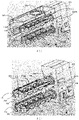
- FIG. 1 is a perspective view of an ice-making device 2 according to one embodiment of the present invention.
- FIG. 2 is a perspective view of the ice-making device 2 shown in FIG. 1 with a bearing portion 24 supporting rotation shafts of ice-making discs 10A, 10B removed.
- FIG. 3 is a perspective view of the ice-making device 2 shown in FIG. 2 with a cover 30 further removed, the cover 30 being configured to guide ice falling from the upper ice-making disc 10A.
- FIG. 4 is a perspective view of the ice-making device 2 shown in FIG. 3 with a fan 40 and an air duct 50 provided on a side of the ice-making discs 10A, 10B further removed.
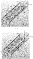
- FIG. 5 is a side view as viewed along arrow A-A in FIG. 2 .
- FIG. 6 is a perspective view of the upper ice-making disc 10A.
- FIG. 7 is a perspective view of the lower ice-making disc 10B.
- the ice-making device 2 has two ice-making discs 10A, 10B arranged up and down.
- the ice-making discs 10A, 10B are formed of a resin material having elasticity.
- the ice-making discs 10A, 10B have a plurality of ice making regions 11 separated by partition walls 12.
- a plurality of pieces of ice having shapes corresponding to shapes of inner surfaces of the ice making regions 11 can be made by freezing liquid, such as drinking water, stored in the ice making regions 11.
- two ice-making discs 10A, 10B are provided, but the present invention is not limited thereto, and there may exist three or more ice-making discs provided up and down.
- the ice-making discs 10A, 10B are provided to be substantially completely overlapped in the up-down direction, but the present invention is not limited thereto.
- a plurality of ice-making discs can be provided with slight misalignment in a lateral direction in a plan view. In order to suppress an increase in an occupied area in a plan view, preferably, 70% or more, and more preferably, 80% or more, of the ice-making discs arranged up and down are overlapped.
- a liquid supply port 60 for supplying liquid to the ice-making disc 10A is provided above the upper ice-making disc 10A.
- liquid stored in a container provided in the refrigerator can be supplied from the liquid supply port 60 to the ice-making disc 10A, or the liquid supply port 60 can be directly connected with a water pipe, or the like.
- flow of the liquid supplied from the liquid supply port 60 to the upper ice-making disc 10 in the ice-making discs 10A, 10B will be briefly described in detail later as follows.
- the liquid supplied from the liquid supply port 60 to one ice making region 11 of the upper ice-making disc 10A flows to the ice making regions 11 adjacent in sequence through a slit 13 while being stored in the ice making region 11. Further, the liquid flows down to the lower ice-making disc 10B through a hole 14 provided in one ice making region 11 of the upper ice-making disc 10A. Then, in the lower ice-making disc 10B, the liquid flows to the ice making regions 11 adjacent in sequence through a slit 13 while being stored in the ice making region 11. Thus, the liquid is stored in each ice making region 11 of the ice-making discs 10A, 10B.
- a fan 40 is provided above the upper ice-making disc 10A and configured to supply gas to an upper space of the ice-making disc 10A.
- the cooled gas passing through an evaporator of the refrigerator is introduced into the ice-making device 2 by the fan 40 and supplied to the upper space of the ice-making disc 10A.
- the ice-making device 2 has an air duct 50 provided on a side of the ice-making discs 10A, 10B and connected between the upper space of the upper ice-making disc 10A and an upper space of the lower ice-making disc 10B.
- the cold gas passing through the evaporator of the refrigerator is supplied by the fan 40, and flows through the upper space of the upper ice-making disc 10A and the upper space of the lower ice-making disc 10B.
- the liquid stored in the ice-making discs 10A, 10B is frozen and ice is formed. Flow of this gas is described in detail later with reference to FIG. 5 .
- the ice-making device 2 further has a rotating mechanism 20 for rotating the two ice-making discs 10A, 10B, and a bearing portion 24.
- Driving shaft portions 15 and non-driving shaft portions 16 are provided at two ends of the ice-making discs 10A, 10B.
- the driving shaft portions 15 of the ice-making discs 10A, 10B are mounted to holding portions 22A, 22B at an upper portion and a lower portion of the rotating mechanism 20 respectively.
- the holding portions 22A, 22B are rotated by an electric motor provided in the rotating mechanism 20.
- the non-driving shaft portions 16 of the ice-making discs 10A, 10B are inserted into an upper hole and a lower hole of the bearing portion 24 respectively.
- the ice-making discs 10A, 10B are rotated about rotation axes Xa, Xb by a driving force of the rotating mechanism 20 respectively.
- a rotation position of the ice-making discs 10A, 10B there exists an ice making position where upper surfaces 18 of the ice-making discs 10A, 10B face upwards and the liquid can be stored.
- the upper surfaces 18 of the ice-making discs 10A, 10B are horizontal, but the upper surfaces 18 can be slightly inclined.
- the ice release position where the ice formed in the ice making region 11 is released and falls.
- the upper surface 18 is required to become downward, but does not have to be horizontal, and can be inclined downwards.
- the upper surfaces 18 of the ice-making discs 10A, 10B are rotated towards the upper ice making position by the driving force of the rotating mechanism 20, such that the upper surface 18 becomes downward, and projections 17 provided at end portions on the non-driving shaft portion 16 sides of the ice-making discs 10A, 10B abut against stoppers provided at the bearing portion 24.
- the rotating mechanism 20 is continuously driven after the abutment, the non-driving shaft portion 16 side of the ice-making discs 10A, 10B is substantially stopped from rotating, and the driving shaft portion 15 side is continuously rotated.
- the ice-making discs 10A, 10B made of the elastic material are twisted, and then, the ice is released from each ice making region 11 and falls down due to gravity. Therefore, a stop position where the upper surfaces 18 of the ice-making discs 10A, 10B are simultaneously twisted downwards is the ice release position.
- the rotating mechanism 20 has one electric motor, and the two ice-making discs 10A, 10B are rotated simultaneously by a gear transmission mechanism.
- the present invention is not limited thereto, and the two ice-making discs 10A, 10B can be rotated separately. Any known ice release mechanism can be used as a mechanism for rotating and twisting the ice-making discs 10A, 10B to release the ice. A travel way of the ice falling from the ice-making discs 10A, 10B is described in detail later with reference to FIG. 5 .
- the ice-making discs 10A, 10B are provided with 2 rows of 5 ice making regions 11 (10 ice making regions 11 in total) which are separated by the partition wall 12.
- the partition wall 12 is provided with the slit 13.
- the slit 13 is provided from a position at a prescribed height h from a bottom surface of the ice making region 11 to an upper end of the partition wall 12. Therefore, the liquid in the ice making region 11 flows into the adjacent ice making region 11 once a liquid level exceeds the prescribed height h.
- the liquid can be stored in each ice making region 11 up to the height h.
- the liquid supply port 60 is provided above one of the two ice making regions 11 located at the end portion on the non-driving shaft portion 16 side of the upper ice-making disc 10A.
- the slits 13 are provided between two ice making regions 11 in adjacent rows located at the end portion on the non-driving shaft portion 16 side, and between two ice making regions 11 in adjacent rows located at the end portion on the driving shaft portion 15 side. Furthermore, the slit 13 is provided between the ice making regions 11 adjacent in a row direction. Further, the hole 14 for dropping the liquid is provided in a lower portion of one of the two ice making regions 11 located at the end portion on the driving shaft portion 15 side.
- the liquid supplied from the liquid supply port 60 to one ice making region 11 at the end portion on the non-driving shaft portion 16 side flows from the non-driving shaft portion 16 side to the driving shaft portion 15 side in two groups (one for each row) as indicated by the dotted arrows in FIG. 6 , and flows downwards from the hole 14 of the one ice making region 11 at the end portion on the non-driving shaft portion 16 side.
- the liquid having the liquid level height h is stored in the ice making regions 11 of the upper ice-making disc 10A other than the ice making region 11 having the hole 14.
- the slits 13 are provided between two ice making regions 11 in adjacent rows located at the end portion on the non-driving shaft portion 16 side, and between two ice making regions 11 in adjacent rows located at the end portion on the driving shaft portion 15 side. Furthermore, the slit 13 is provided between the ice making regions 11 adjacent in a row direction, and the lower ice-making disc 10B is not provided with the ice making region 11 having the hole 14.
- the liquid flowing from the upper ice-making disc 10A downwards to one ice making region 11 at the end portion on the driving shaft portion 15 side flows from the driving shaft portion 15 side to the non-driving shaft portion 16 side in two groups (one for each row) as indicated by the dotted arrows in FIG. 7 .
- the liquid having the liquid level height h is stored in all the ice making regions 11 of the lower ice-making disc 10B.
- the liquid may smoothly flow in two groups (one for each row).
- the above arrangement of the slits 13 in the ice-making discs 10A, 10B is merely an example, and any other arrangement of the slit 13 can be adopted depending on the arrangement of the ice making region 11.
- one hole 14 is provided at the upper ice-making disc 10A in the present embodiment, the present invention is not limited thereto, and the holes 14 for the liquid to fall can be provided at the lower portions of a plurality of ice making regions 11 of the ice-making disc 10A.
- the liquid supply port 60 can be provided to supply liquid to one ice making region 11 of the uppermost ice-making disc 10.
- the present invention is not limited to the case where the liquid is supplied from the liquid supply port 60 to one ice making region 11, and the liquid can be supplied from the liquid supply port 60 to a plurality of ice making regions 11.
- the slits 13 are provided in accordance with positions of the plurality of liquid supply ports 60, such that the flows of the liquid from the liquid supply ports 60 do not interfere with each other.
- the liquid in the case where the liquid is supplied to at least one ice making region 11 through the slit 13 provided at the partition wall 12 of the ice-making discs 10A, 10B, the liquid can be supplied to another ice making region 11 while stored in the ice making region 11.
- the flow of the gas in the ice-making device 2 is explained with reference to FIG. 5 .
- the flow of the gas is indicated by a dot-and-dash arrow.
- the upper space of the upper ice-making disc 10A is closed at the right end portion in the drawing by a wall 34 (refer to FIGS. 1 and 2 ). Therefore, the gas cooled by the evaporator of the refrigerator and discharged downwards by the fan 40 flows from the right side to the left side of the drawing in a lower portion of the fan 40 and the upper space of the upper ice-making disc 10A.
- the liquid stored in each ice making region 11 of the ice-making disc 10A is cooled by the flow of the gas discharged downwards.
- the gas flowing in the lower portion of the fan 40 and the upper space of the ice-making disc 10A flows into the air duct 50, and the air duct 50 is provided on the side of the ice-making discs 10A, 10B and connected between the upper space of the upper ice-making disc 10A and the upper space of the lower ice-making disc 10B.
- the air duct 50 is provided with a flow path having a curved surface or an inclined surface, such that the gas flows smoothly with less pressure loss.
- the gas flows from top to bottom in the air duct 50 and flows into the upper space of the lower ice-making disc 10B.
- the gas flows from the left side to the right side of the drawing in the upper space of the lower ice-making disc 10B.
- the liquid stored in each ice making region 11 of the ice-making disc 10B is cooled by this flow.
- the gas flowing in the upper space of the ice-making disc 10B flows to the outside of the ice-making device 2 from an opening 32 (refer to FIGS. 1 and 2 ) provided in the cover 30.
- the gas flowing to the outside of the ice-making device 2 flows in the refrigerator, and is cooled by the evaporator of the refrigerator again.
- the fan 40 is provided above the upper ice-making disc 10A, but the present invention is not limited thereto.
- the fan 40 can be provided on the lower ice-making disc 10B side, and the gas may also flow from the lower ice-making disc 10B side to the upper ice-making disc 10A side by means of the air duct 50.
- the fan 40 can be provided at one of the ice-making discs 10, or the fan 40 can be provided at a plurality of ice-making discs 10 having different heights.
- the ice-making device 2 has the fan 40 for supplying the gas to the upper space of at least one ice-making disc 10A, and the air duct 50 provided on the side of the ice-making discs 10A, 10B and connected between the upper space of the upper ice-making disc 10A and the upper space of the lower ice-making disc 10B.
- the fan 40 may also be referred to as a gas supply portion.
- the gas when the gas is supplied from the fan 40 to at least one ice-making disc 10A, the gas can be supplied to the other ice-making disc 10B through the air duct 50 provided on the side of the ice-making discs 10A, 10B.
- the liquid stored in the ice-making discs 10A, 10B can be efficiently cooled with a small number of fans 40.
- FIG. 9 shows a side sectional view of the refrigerator for explaining a variant of the ice-making device 2.
- a cold gas discharge port for example, opening 112
- a suction port 42 for introducing cold gas into the ice-making device 2.
- the ice-making device 2 is provided near the opening 112, and the opening 112 is configured to feed the cold gas passing through the evaporator 126 of the refrigerator 100 into a freezing chamber 110.
- the suction port when the suction port is provided on a side of or above the upper space of the ice-making disc 10A, the gas can be sucked into the upper space of one ice-making disc 10A.
- the suction port 42 serving as the gas supply portion is provided on a side of the upper space of the ice-making disc 10A. In this way, the cold gas passing through the evaporator 126 can be directly sucked into the upper space of the ice-making disc 10A.
- the suction port is provided at a position opposite to the side where the air duct 50 is provided.
- the ice-making device 2 may have the gas supply portions 40, 42 for supplying the gas to the upper space of at least one ice-making disc 10A, and the air duct 50 provided on the side of the ice-making discs 10A, 10B and connected between the upper space of the upper ice-making disc 10A and the upper space of the lower ice-making disc 10B.
- FIG. 5 A following travel way of the ice released and dropped from the ice-making discs 10A, 10B after the ice-making discs 10A, 10B are rotated to the ice release position by the rotating mechanism 20 will be described with reference to FIG. 5 .
- the ice dropped from the lower ice-making disc 10B directly falls into the storage container 70 provided below the ice-making device 2.
- the lower ice-making disc 10B the ice dropped from the upper ice-making disc 10A is unable to directly enter the storage container 70.
- the cover 30 is provided at an upper portion of the lower ice-making disc 10B and configured to guide the ice falling from the upper ice-making disc 10A to fall on the side of the lower ice-making disc 10B.
- the cover 30 in the present embodiment has a curved surface. As such, the ice falling from the upper ice-making disc 10A moves along the curved surface and falls from the side of the ice-making device 2 into the storage container 70 provided below the ice-making device 2. As such, the ice falling from the upper ice-making disc 10A can be smoothly stored in the storage container 70 while damage to the ice and a machine is avoided.
- the cover 30 does not necessarily have the curved surface, and can have any other shape as long as a traveling direction of the falling ice can be changed to an obliquely downward direction, so as to drop the ice on the side of the lower ice-making disc 10B.
- the traveling direction of the falling ice can also be changed to the obliquely downward direction.
- the cover 30 can have a shape with both the curved surface and the inclined surface. As described above, the cover 30 is provided therein with the plurality of slit-shaped openings 32 for the gas supplied by the fan 40 to pass through.
- the cover 30 is provided at the upper portion of the lower ice-making disc 10B and configured to guide the ice falling from the upper ice-making disc 10A to fall on the side of the lower ice-making disc 10B, the ice of the ice-making discs 10A, 10B arranged up and down can be accurately stored in the storage container 70.
- the ice-making device 2 in which the ice-making discs 10A, 10B are provided up and down can be realized, and the ice-making device 2 capable of supplying more ice while suppressing a reduction in a storage rate of the refrigerator can be provided.
- FIG. 8 is a side sectional view illustrating one example of the refrigerator 100 having the ice-making device 2.
- the refrigerator 100 having the ice-making device 2 according to the above embodiment will be described with reference to FIG. 8 .
- the ice-making device 2 and a liquid supply device 130 are depicted largely as compared to the refrigerator for illustrative purposes.
- the ice-making device 2 is provided on a rear side of the freezing chamber 110 of the refrigerator 100, and the storage container 70 of the ice is provided below the ice-making device.
- the refrigerator 100 has therein the liquid supply device 130 for supplying liquid to the ice-making discs 10A, 10B of the ice-making device 2.
- the liquid stored in a water tank 132 is supplied to a pipe 136 side by a discharge force of a pump 134. Then, the liquid flowing down through the pipe 136 is supplied from the liquid supply port 60 to the upper ice-making disc 10A of the ice-making device 2.
- the refrigerator 100 has a cooling mechanism 120 which forms a cooling cycle mainly by a compressor 122, a condenser 124 and the evaporator 126 to supply the cold gas into the refrigerator.
- the gas circulating in the refrigerator 100 is cooled while passing through the evaporator 126.
- the gas cooled by a heat exchange in the evaporator 126 is blown into the freezing chamber 110 by a refrigerator fan 128 through the opening 112.
- Apart of the gas blown into the freezing chamber 110 is sucked into the ice-making device 2 by the fan 40 of the ice-making device 2 and supplied to the upper space of the upper ice-making disc 10A.
- the gas sucked into the ice-making device 2 flows from the upper space of the upper ice-making disc 10A to the upper space of the lower ice-making disc 10B by means of the air duct, and flows to the outside of the ice-making device 2 from the opening provided in the cover.
- the outflow gas flows towards the cooling mechanism 120 side by means of an opening 114 and is cooled while passing through the evaporator 126 again.
- the cooled gas is supplied into the ice-making device 2 without interruption, and the liquid in the ice-making discs 10A, 10B is frozen to make ice.
- the refrigerator 100 having the ice-making device 2 in which the ice-making discs 10A, 10B are provided up and down the occupied area in a plan view can be reduced as compared with the case where the ice-making discs are laterally arranged side by side.
- the refrigerator capable of supplying more ice while suppressing the reduction in the storage rate can be provided.
- the ice-making device 2 can have a gas suction port 42 instead of the fan 40. In this case, by directly sucking the cold gas blown into the freezing chamber 110 through the opening 112 from the gas suction port 42 into the ice-making device 2, the cold gas can be supplied to the upper space of the upper ice-making disc 10A.
- the ice-making device 2 is provided in the freezing chamber 110, but the present invention is not limited thereto. Since the plurality of ice-making discs 10A, 10B are provided up and down, the ice-making device 2 can be relatively easily provided in a door of the refrigerator 100. In this case, however, there may exist a risk that water in the ice-making disc is scattered due to opening and closing operations of the door.
- guide rods 19 can be mounted to abut against protrusions of both side surfaces of the ice-making discs 10A, 10B along the row of the ice making regions 11 (i.e., along a longer direction).
- the guide rods 19 extend upwards from the upper surfaces 18 of the ice-making discs 10A, 10B.
- the water splashed due to the opening and closing operations of the door hits the guide rods 19 and returns to the ice making regions 11 of the ice-making discs 10A, 10B along inner surfaces of the guide rods 19.
- the liquid in the ice-making discs 10A, 10B can be prevented from spilling outwards even when the door is opened and closed.
- the protrusions of the ice-making discs 10A, 10B and the guide rods 19 are formed of a flexible resin material, the protrusions and the guide rods 19 can sufficiently accommodate a stress when the ice-making discs 10A, 10B are twisted for ice release and a vibration when the refrigerator door is strongly opened and closed.
- the guide rods 19 extending upwards from the upper surfaces 18 of the ice-making discs 10A, 10B are provided on both side surfaces in the longer direction of the ice-making discs 10A, 10B, the liquid in the ice-making discs 10A, 10B can be effectively prevented from being splashed with the opening and closing operations of the door.
- a plurality of pieces of ice are made with the ice making regions 11 of the ice-making discs 10A, 10B in the above embodiment, but there may exist an ice crusher below the ice-making device 2 for crushing the ice made with the ice-making device 2.
- the liquid stored in the water tank 132 of the liquid supply device 130 is supplied to the ice-making device 2, but the ice-making device 2 can be connected to a water supply pipe, and the liquid can be directly supplied from the water supply pipe to the ice-making device 2.
- a separate ice-making device 2 independent of the refrigerator may also be realized when there exists a cooling mechanism dedicated to the ice-making device 2.
Landscapes
- Engineering & Computer Science (AREA)
- Physics & Mathematics (AREA)
- Mechanical Engineering (AREA)
- Thermal Sciences (AREA)
- General Engineering & Computer Science (AREA)
- Chemical & Material Sciences (AREA)
- Combustion & Propulsion (AREA)
- Devices That Are Associated With Refrigeration Equipment (AREA)
- Cold Air Circulating Systems And Constructional Details In Refrigerators (AREA)
Abstract
Description
- The present invention relates to an ice-making device for making ice using an ice-making disc and a refrigerator having the same.
- A refrigerator having an ice-making device for making ice using an ice-making disc is widely used. An ice-making device which has a plurality of ice-making discs and may make more ice is proposed to be provided in such a refrigerator (for example, refer to patent document 1). In the refrigerator described in patent document 1, the plurality of ice-making discs are arranged in a depth direction of the refrigerator to avoid an increase in a size of the ice-making device in a width direction of the refrigerator.
- Patent document 1:
JP publication No. 2003-279221 - Compared with one ice-making disc, a plane area of the plurality of ice-making discs in the refrigerator is directly proportional to a number of the ice-making discs, thus lowering a storage rate (i.e., a space utilization rate) of the refrigerator.
- In view of this, the existing ice-making device and refrigerator are necessary to be improved to solve the above-mentioned problem.
- An object of the present invention is to provide an ice-making device and a refrigerator having the same, which are capable of supplying more ice while suppressing a reduction in a storage rate of the refrigerator.
- The present invention is directed to an ice-making device comprising a plurality of ice-making discs arranged up and down and a rotating mechanism, wherein the rotating mechanism is capable of rotating the plurality of ice-making discs between an ice making position where liquid can be stored and an ice release position where formed ice is released and dropped, a cover is provided at an upper portion of the lower ice-making disc, and the cover guides the ice falling from the upper ice-making disc to fall on a side of the lower ice-making disc.
- According to the present invention, more ice can be supplied by means of a plurality of ice-making discs. Furthermore, since the plurality of ice-making discs are arranged up and down, when the ice-making discs are arranged in the refrigerator, an occupied area in a plan view can be reduced as compared with a case where the plurality of ice-making discs are arranged laterally. Since a cover is provided at an upper portion of a lower ice-making disc and configured to guide ice falling from an upper ice-making disc to fall on a side of the lower ice-making disc, even when the plurality of ice-making discs are arranged up and down, the ice from the upper ice-making disc does not interfere with the lower ice-making disc, but may fall into a storage container provided below the ice-making device.
- As such, the present invention provides the ice-making device capable of supplying more ice while suppressing the reduction in the storage rate of the refrigerator.
- Further, the ice-making device further comprising a gas supply portion and an air duct, wherein the gas supply portion supplies gas to an upper space of at least one of the ice-making discs, and the air duct is provided on a side of the ice-making disc and connected between the upper space of the ice-making disc supplied with the gas from the gas supply portion and the upper space of another ice-making disc.
- In the ice-making device according to the present invention, when gas is supplied to at least one ice-making disc from a gas supply portion including a fan or a gas suction port, the gas may also be supplied to another ice-making disc through an air duct provided on a side of the ice-making disc. Thus, liquid stored in the plurality of ice-making discs can be efficiently cooled with a small number of gas supply portions.
- Further, the ice-making disc has a plurality of ice making regions separated by a partition wall, and a slit is provided at the partition wall to allow liquid in the ice making regions to flow into the adjacent ice making regions once a liquid level exceeds a prescribed height.
- In the ice-making device according to the present invention, when liquid is supplied to at least one ice making region through a slit provided at a partition wall of the ice-making disc, the liquid can also be supplied to another ice making region while stored in the ice making region.
- Further, the ice-making device further comprising a liquid supply port for supplying liquid, wherein the liquid supply port is provided at at least one of the ice making regions of the uppermost ice-making disc, and a hole for dropping liquid is provided in a lower portion of at least one of the ice making regions of the upper ice-making disc other than the ice making region provided with the liquid supply port.
- In the ice-making device according to the present invention, since a liquid supply port for supplying liquid is provided in at least one ice making region of an uppermost ice-making disc, and a hole for dropping liquid is provided in a lower portion of at least one ice making region of the upper ice-making disc other than the ice making region provided with the liquid supply port, the liquid can be efficiently supplied into all ice making regions of the upper and lower ice-making discs without using special power.
- The present invention is also directed to a refrigerator comprising the ice-making device.
- As such, the refrigerator may supply more ice while suppressing the reduction in the storage rate.
- The present invention has the beneficial effect that the ice-making device and the refrigerator having the same according to the present invention are capable of supplying more ice while suppressing the reduction in the storage rate of the refrigerator.
-
-
FIG. 1 is a perspective view of an ice-making device according to one embodiment of the present invention. -
FIG. 2 is a perspective view of the ice-making device shown inFIG. 1 with a bearing portion supporting rotation shafts of ice-making discs removed. -
FIG. 3 is a perspective view of the ice-making device shown inFIG. 2 with a cover for guiding ice falling from the upper ice-making disc further removed. -
FIG. 4 is a perspective view of the ice-making device shown inFIG. 3 with a fan and an air duct provided on a side of the ice-making discs further removed. -
FIG. 5 is a side view as viewed in a direction of arrow A-A inFIG. 2 . -
FIG. 6 is a perspective view of the upper ice-making disc. -
FIG. 7 is a perspective view of the lower ice-making disc. -
FIG. 8 is a side sectional view of a refrigerator having the ice-making device. -
FIG. 9 is a side sectional view of the refrigerator to show a variant embodiment of the ice-making device. -
- 2: ice-making device
- 10, 10A, 10B: ice-making disc
- 11: ice making region
- 12: partition wall
- 13: slit
- 14: hole
- 15: driving shaft portion
- 16: non-driving shaft portion
- 17: projection
- 18: upper surface
- 19: guide rod
- 20: rotating mechanism
- 22A, 22B: holding portion
- 24: bearing portion
- 30: cover
- 34: wall
- 40: fan
- 42: suction port
- 50: air duct
- 60: liquid supply port
- 70: storage container
- 100: refrigerator
- 110: freezing chamber
- 112: opening
- 114: opening
- 120: cooling mechanism
- 122: compressor
- 124: condenser
- 126: evaporator
- 128: refrigerator fan
- 130: liquid supply device
- 132: water tank
- 134: pump
- 136: pipe
- Xa, Xb: rotation axis
- In order to make the objects, technical solutions and advantages of the present invention more apparent, the present invention will be described in detail with reference to the accompanying drawings and specific embodiments.
- Hereinafter, the embodiment of the present invention will be described in detail based on the accompanying drawings. In addition, a device described below serves as a device for embodying the technical idea of the present invention, and the present invention is not limited to the following content unless otherwise specified. In order to clarify the description, the sizes, positional relationships, or the like, of elements in each drawing may be exaggeratedly shown. In the specification and the accompanying drawings, the up-down direction is shown assuming a refrigerator provided on the floor.
-
FIG. 1 is a perspective view of an ice-makingdevice 2 according to one embodiment of the present invention.FIG. 2 is a perspective view of the ice-makingdevice 2 shown inFIG. 1 with a bearingportion 24 supporting rotation shafts of ice-makingdiscs FIG. 3 is a perspective view of the ice-makingdevice 2 shown inFIG. 2 with acover 30 further removed, thecover 30 being configured to guide ice falling from the upper ice-makingdisc 10A.FIG. 4 is a perspective view of the ice-makingdevice 2 shown inFIG. 3 with afan 40 and anair duct 50 provided on a side of the ice-makingdiscs FIG. 5 is a side view as viewed along arrow A-A inFIG. 2 .FIG. 6 is a perspective view of the upper ice-makingdisc 10A.FIG. 7 is a perspective view of the lower ice-makingdisc 10B. - Here, a case where the ice-making
device 2 is provided in a refrigerator will be described as an example. The ice-makingdevice 2 has two ice-makingdiscs discs discs ice making regions 11 separated bypartition walls 12. A plurality of pieces of ice having shapes corresponding to shapes of inner surfaces of theice making regions 11 can be made by freezing liquid, such as drinking water, stored in theice making regions 11. - In the illustrated embodiment of the present invention, two ice-making
discs discs - As shown in
FIG. 4 , aliquid supply port 60 for supplying liquid to the ice-makingdisc 10A is provided above the upper ice-makingdisc 10A. In this case, for example, liquid stored in a container provided in the refrigerator can be supplied from theliquid supply port 60 to the ice-makingdisc 10A, or theliquid supply port 60 can be directly connected with a water pipe, or the like. With reference toFIGS. 6 and 7 , flow of the liquid supplied from theliquid supply port 60 to the upper ice-making disc 10 in the ice-makingdiscs - The liquid supplied from the
liquid supply port 60 to oneice making region 11 of the upper ice-makingdisc 10A flows to theice making regions 11 adjacent in sequence through aslit 13 while being stored in theice making region 11. Further, the liquid flows down to the lower ice-makingdisc 10B through ahole 14 provided in oneice making region 11 of the upper ice-makingdisc 10A. Then, in the lower ice-makingdisc 10B, the liquid flows to theice making regions 11 adjacent in sequence through aslit 13 while being stored in theice making region 11. Thus, the liquid is stored in eachice making region 11 of the ice-makingdiscs - A
fan 40 is provided above the upper ice-makingdisc 10A and configured to supply gas to an upper space of the ice-makingdisc 10A. In the present embodiment, the cooled gas passing through an evaporator of the refrigerator is introduced into the ice-makingdevice 2 by thefan 40 and supplied to the upper space of the ice-makingdisc 10A. The ice-makingdevice 2 has anair duct 50 provided on a side of the ice-makingdiscs disc 10A and an upper space of the lower ice-makingdisc 10B. With such a configuration, the cold gas passing through the evaporator of the refrigerator is supplied by thefan 40, and flows through the upper space of the upper ice-makingdisc 10A and the upper space of the lower ice-makingdisc 10B. Thus, the liquid stored in the ice-makingdiscs FIG. 5 . - The ice-making
device 2 further has arotating mechanism 20 for rotating the two ice-makingdiscs portion 24. Drivingshaft portions 15 andnon-driving shaft portions 16 are provided at two ends of the ice-makingdiscs shaft portions 15 of the ice-makingdiscs portions rotating mechanism 20 respectively. The holdingportions rotating mechanism 20. Thenon-driving shaft portions 16 of the ice-makingdiscs portion 24 respectively. - With such a configuration, the ice-making
discs rotating mechanism 20 respectively. At a rotation position of the ice-makingdiscs upper surfaces 18 of the ice-makingdiscs ice making regions 11 of the ice-makingdiscs upper surfaces 18 of the ice-makingdiscs upper surfaces 18 can be slightly inclined. Further, at the rotation position of the ice-makingdiscs ice making region 11 is released and falls. In the ice release position, in order to drop the ice, theupper surface 18 is required to become downward, but does not have to be horizontal, and can be inclined downwards. - The upper surfaces 18 of the ice-making
discs rotating mechanism 20, such that theupper surface 18 becomes downward, andprojections 17 provided at end portions on thenon-driving shaft portion 16 sides of the ice-makingdiscs portion 24. When therotating mechanism 20 is continuously driven after the abutment, thenon-driving shaft portion 16 side of the ice-makingdiscs shaft portion 15 side is continuously rotated. As such, the ice-makingdiscs ice making region 11 and falls down due to gravity. Therefore, a stop position where theupper surfaces 18 of the ice-makingdiscs - In the present embodiment, the rotating
mechanism 20 has one electric motor, and the two ice-makingdiscs discs discs discs FIG. 5 . - As shown in
FIGS. 6 and 7 , the ice-makingdiscs ice making regions 11 in total) which are separated by thepartition wall 12. However, the arrangement of theice making region 11 is not limited thereto. Thepartition wall 12 is provided with theslit 13. Theslit 13 is provided from a position at a prescribed height h from a bottom surface of theice making region 11 to an upper end of thepartition wall 12. Therefore, the liquid in theice making region 11 flows into the adjacentice making region 11 once a liquid level exceeds the prescribed height h. Thus, when supplied to oneice making region 11 of the ice-makingdiscs ice making region 11 up to the height h. - The
liquid supply port 60 is provided above one of the twoice making regions 11 located at the end portion on thenon-driving shaft portion 16 side of the upper ice-makingdisc 10A. Theslits 13 are provided between twoice making regions 11 in adjacent rows located at the end portion on thenon-driving shaft portion 16 side, and between twoice making regions 11 in adjacent rows located at the end portion on the drivingshaft portion 15 side. Furthermore, theslit 13 is provided between theice making regions 11 adjacent in a row direction. Further, thehole 14 for dropping the liquid is provided in a lower portion of one of the twoice making regions 11 located at the end portion on the drivingshaft portion 15 side. - With the above arrangement of the
slit 13 and thehole 14, the liquid supplied from theliquid supply port 60 to oneice making region 11 at the end portion on thenon-driving shaft portion 16 side flows from thenon-driving shaft portion 16 side to the drivingshaft portion 15 side in two groups (one for each row) as indicated by the dotted arrows inFIG. 6 , and flows downwards from thehole 14 of the oneice making region 11 at the end portion on thenon-driving shaft portion 16 side. Thus, the liquid having the liquid level height h is stored in theice making regions 11 of the upper ice-makingdisc 10A other than theice making region 11 having thehole 14. By providing the slit only between theice making regions 11 of the adjacent rows at theice making regions 11 of both end portions, the liquid may smoothly flow in two groups (one for each row). - For the lower ice-making
disc 10B, theslits 13 are provided between twoice making regions 11 in adjacent rows located at the end portion on thenon-driving shaft portion 16 side, and between twoice making regions 11 in adjacent rows located at the end portion on the drivingshaft portion 15 side. Furthermore, theslit 13 is provided between theice making regions 11 adjacent in a row direction, and the lower ice-makingdisc 10B is not provided with theice making region 11 having thehole 14. - With the above arrangement of the
slit 13, the liquid flowing from the upper ice-makingdisc 10A downwards to oneice making region 11 at the end portion on the drivingshaft portion 15 side flows from the drivingshaft portion 15 side to thenon-driving shaft portion 16 side in two groups (one for each row) as indicated by the dotted arrows inFIG. 7 . Thus, the liquid having the liquid level height h is stored in all theice making regions 11 of the lower ice-makingdisc 10B. In the lower ice-makingdisc 10B as well, by providing the slit only between theice making regions 11 of the adjacent rows at theice making regions 11 of both end portions, the liquid may smoothly flow in two groups (one for each row). - However, the above arrangement of the
slits 13 in the ice-makingdiscs slit 13 can be adopted depending on the arrangement of theice making region 11. Although onehole 14 is provided at the upper ice-makingdisc 10A in the present embodiment, the present invention is not limited thereto, and theholes 14 for the liquid to fall can be provided at the lower portions of a plurality ofice making regions 11 of the ice-makingdisc 10A. - In addition, in a case of three or more ice-making discs 10 arranged up and down, the
liquid supply port 60 can be provided to supply liquid to oneice making region 11 of the uppermost ice-making disc 10. In addition, the present invention is not limited to the case where the liquid is supplied from theliquid supply port 60 to oneice making region 11, and the liquid can be supplied from theliquid supply port 60 to a plurality ofice making regions 11. In this case, preferably, theslits 13 are provided in accordance with positions of the plurality ofliquid supply ports 60, such that the flows of the liquid from theliquid supply ports 60 do not interfere with each other. - As above, in the case where the liquid is supplied to at least one
ice making region 11 through theslit 13 provided at thepartition wall 12 of the ice-makingdiscs ice making region 11 while stored in theice making region 11. - Further, since there exists the
liquid supply port 60 for supplying the liquid to at least oneice making region 11 of the uppermost ice-makingdisc 10A, and thehole 14 for dropping the liquid is provided in the lower portion of at least oneice making region 11 of the upper ice-makingdisc 10A other than theice making region 11 provided with theliquid supply port 60, the liquid can be efficiently supplied into all theice making regions 11 of the upper and lower ice-makingdiscs - The flow of the gas in the ice-making
device 2 is explained with reference toFIG. 5 . InFIG. 5 , the flow of the gas is indicated by a dot-and-dash arrow. The upper space of the upper ice-makingdisc 10A is closed at the right end portion in the drawing by a wall 34 (refer toFIGS. 1 and 2 ). Therefore, the gas cooled by the evaporator of the refrigerator and discharged downwards by thefan 40 flows from the right side to the left side of the drawing in a lower portion of thefan 40 and the upper space of the upper ice-makingdisc 10A. The liquid stored in eachice making region 11 of the ice-makingdisc 10A is cooled by the flow of the gas discharged downwards. Then, the gas flowing in the lower portion of thefan 40 and the upper space of the ice-makingdisc 10A flows into theair duct 50, and theair duct 50 is provided on the side of the ice-makingdiscs disc 10A and the upper space of the lower ice-makingdisc 10B. Theair duct 50 is provided with a flow path having a curved surface or an inclined surface, such that the gas flows smoothly with less pressure loss. - Then, the gas flows from top to bottom in the
air duct 50 and flows into the upper space of the lower ice-makingdisc 10B. In addition, the gas flows from the left side to the right side of the drawing in the upper space of the lower ice-makingdisc 10B. The liquid stored in eachice making region 11 of the ice-makingdisc 10B is cooled by this flow. Then, the gas flowing in the upper space of the ice-makingdisc 10B flows to the outside of the ice-makingdevice 2 from an opening 32 (refer toFIGS. 1 and 2 ) provided in thecover 30. The gas flowing to the outside of the ice-makingdevice 2 flows in the refrigerator, and is cooled by the evaporator of the refrigerator again. - In the present embodiment, the
fan 40 is provided above the upper ice-makingdisc 10A, but the present invention is not limited thereto. For example, thefan 40 can be provided on the lower ice-makingdisc 10B side, and the gas may also flow from the lower ice-makingdisc 10B side to the upper ice-makingdisc 10A side by means of theair duct 50. Furthermore, in the case of three or more ice-making discs 10 arranged up and down, thefan 40 can be provided at one of the ice-making discs 10, or thefan 40 can be provided at a plurality of ice-making discs 10 having different heights. - As above, the ice-making
device 2 has thefan 40 for supplying the gas to the upper space of at least one ice-makingdisc 10A, and theair duct 50 provided on the side of the ice-makingdiscs disc 10A and the upper space of the lower ice-makingdisc 10B. Thefan 40 may also be referred to as a gas supply portion. Thus, when the gas is supplied from thefan 40 to at least one ice-makingdisc 10A, the gas can be supplied to the other ice-makingdisc 10B through theair duct 50 provided on the side of the ice-makingdiscs discs fans 40. - In the above embodiment, the ice-making
device 2 has thefan 40 supplying the gas, but the present invention is not limited thereto.FIG. 9 shows a side sectional view of the refrigerator for explaining a variant of the ice-makingdevice 2. As shown inFIG. 9 , in a case where a cold gas discharge port (for example, opening 112) is provided around the ice-makingdevice 2, even without thefan 40, the same function as described above can be achieved with asuction port 42 for introducing cold gas into the ice-makingdevice 2. - In
FIG. 9 , the ice-makingdevice 2 is provided near theopening 112, and theopening 112 is configured to feed the cold gas passing through theevaporator 126 of therefrigerator 100 into a freezingchamber 110. In this case, when the suction port is provided on a side of or above the upper space of the ice-makingdisc 10A, the gas can be sucked into the upper space of one ice-makingdisc 10A. InFIG. 9 , thesuction port 42 serving as the gas supply portion is provided on a side of the upper space of the ice-makingdisc 10A. In this way, the cold gas passing through theevaporator 126 can be directly sucked into the upper space of the ice-makingdisc 10A. In the case where thesuction port 42 is provided on the side of the upper space of the ice-makingdisc 10A, in consideration of the flow of the gas, preferably, the suction port is provided at a position opposite to the side where theair duct 50 is provided. - During collective expression of the case of having the
fan 40 and the case of having thesuction port 42, the ice-makingdevice 2 may have thegas supply portions disc 10A, and theair duct 50 provided on the side of the ice-makingdiscs disc 10A and the upper space of the lower ice-makingdisc 10B. - A following travel way of the ice released and dropped from the ice-making
discs discs mechanism 20 will be described with reference toFIG. 5 . As indicated by the dotted arrow ofFIG. 5 , due to gravity, the ice dropped from the lower ice-makingdisc 10B directly falls into thestorage container 70 provided below the ice-makingdevice 2. On the other hand, due to the lower ice-makingdisc 10B, the ice dropped from the upper ice-makingdisc 10A is unable to directly enter thestorage container 70. - In the ice-making
device 2 according to the present embodiment, thecover 30 is provided at an upper portion of the lower ice-makingdisc 10B and configured to guide the ice falling from the upper ice-makingdisc 10A to fall on the side of the lower ice-makingdisc 10B. Further, thecover 30 in the present embodiment has a curved surface. As such, the ice falling from the upper ice-makingdisc 10A moves along the curved surface and falls from the side of the ice-makingdevice 2 into thestorage container 70 provided below the ice-makingdevice 2. As such, the ice falling from the upper ice-makingdisc 10A can be smoothly stored in thestorage container 70 while damage to the ice and a machine is avoided. - However, the
cover 30 does not necessarily have the curved surface, and can have any other shape as long as a traveling direction of the falling ice can be changed to an obliquely downward direction, so as to drop the ice on the side of the lower ice-makingdisc 10B. For example, by using aplanar cover 30 with an inclined surface, the traveling direction of the falling ice can also be changed to the obliquely downward direction. Further, thecover 30 can have a shape with both the curved surface and the inclined surface. As described above, thecover 30 is provided therein with the plurality of slit-shapedopenings 32 for the gas supplied by thefan 40 to pass through. - As above, since the
cover 30 is provided at the upper portion of the lower ice-makingdisc 10B and configured to guide the ice falling from the upper ice-makingdisc 10A to fall on the side of the lower ice-makingdisc 10B, the ice of the ice-makingdiscs storage container 70. Thus, the ice-makingdevice 2 in which the ice-makingdiscs device 2 capable of supplying more ice while suppressing a reduction in a storage rate of the refrigerator can be provided. -
FIG. 8 is a side sectional view illustrating one example of therefrigerator 100 having the ice-makingdevice 2. Next, one example of therefrigerator 100 having the ice-makingdevice 2 according to the above embodiment will be described with reference toFIG. 8 . InFIG. 8 , the ice-makingdevice 2 and aliquid supply device 130 are depicted largely as compared to the refrigerator for illustrative purposes. - The ice-making
device 2 is provided on a rear side of the freezingchamber 110 of therefrigerator 100, and thestorage container 70 of the ice is provided below the ice-making device. Therefrigerator 100 has therein theliquid supply device 130 for supplying liquid to the ice-makingdiscs device 2. In theliquid supply device 130, the liquid stored in awater tank 132 is supplied to apipe 136 side by a discharge force of apump 134. Then, the liquid flowing down through thepipe 136 is supplied from theliquid supply port 60 to the upper ice-makingdisc 10A of the ice-makingdevice 2. - The
refrigerator 100 has acooling mechanism 120 which forms a cooling cycle mainly by acompressor 122, acondenser 124 and theevaporator 126 to supply the cold gas into the refrigerator. The gas circulating in therefrigerator 100 is cooled while passing through theevaporator 126. Then, as indicated by the dot-and-dash arrow, the gas cooled by a heat exchange in theevaporator 126 is blown into the freezingchamber 110 by arefrigerator fan 128 through theopening 112. Apart of the gas blown into the freezingchamber 110 is sucked into the ice-makingdevice 2 by thefan 40 of the ice-makingdevice 2 and supplied to the upper space of the upper ice-makingdisc 10A. The gas sucked into the ice-makingdevice 2 flows from the upper space of the upper ice-makingdisc 10A to the upper space of the lower ice-makingdisc 10B by means of the air duct, and flows to the outside of the ice-makingdevice 2 from the opening provided in the cover. The outflow gas flows towards thecooling mechanism 120 side by means of anopening 114 and is cooled while passing through theevaporator 126 again. By repeating such a gas circulation, the cooled gas is supplied into the ice-makingdevice 2 without interruption, and the liquid in the ice-makingdiscs - As above, in the
refrigerator 100 having the ice-makingdevice 2 in which the ice-makingdiscs FIG. 9 , the ice-makingdevice 2 can have agas suction port 42 instead of thefan 40. In this case, by directly sucking the cold gas blown into the freezingchamber 110 through the opening 112 from thegas suction port 42 into the ice-makingdevice 2, the cold gas can be supplied to the upper space of the upper ice-makingdisc 10A. - In the
refrigerator 100 according to the above embodiment, the ice-makingdevice 2 is provided in the freezingchamber 110, but the present invention is not limited thereto. Since the plurality of ice-makingdiscs device 2 can be relatively easily provided in a door of therefrigerator 100. In this case, however, there may exist a risk that water in the ice-making disc is scattered due to opening and closing operations of the door. - To solve this problem, as shown in
FIGS. 4 and5 , guiderods 19 can be mounted to abut against protrusions of both side surfaces of the ice-makingdiscs guide rods 19 extend upwards from theupper surfaces 18 of the ice-makingdiscs guide rods 19 and returns to theice making regions 11 of the ice-makingdiscs guide rods 19. By thisguide rod 19, the liquid in the ice-makingdiscs - Since the protrusions of the ice-making
discs guide rods 19 are formed of a flexible resin material, the protrusions and theguide rods 19 can sufficiently accommodate a stress when the ice-makingdiscs refrigerator 100 having the ice-makingdevice 2 according to the above embodiment in the door, since theguide rods 19 extending upwards from theupper surfaces 18 of the ice-makingdiscs discs discs - (1) A plurality of pieces of ice are made with the
ice making regions 11 of the ice-makingdiscs device 2 for crushing the ice made with the ice-makingdevice 2. (2) In the above embodiment, the liquid stored in thewater tank 132 of theliquid supply device 130 is supplied to the ice-makingdevice 2, but the ice-makingdevice 2 can be connected to a water supply pipe, and the liquid can be directly supplied from the water supply pipe to the ice-makingdevice 2. (3) A separate ice-makingdevice 2 independent of the refrigerator may also be realized when there exists a cooling mechanism dedicated to the ice-makingdevice 2. - So far, a person skilled in the art shall know that although a plurality of exemplary embodiments of the present invention have been described above in detail, various variations and improvements can be directly determined or deducted from the content disclosed by the present invention without departing from the spirit and scope of the present invention. Therefore, all those variations and improvements shall be deemed to be covered by the scope of the present invention.
Claims (5)
- An ice-making device, comprising: a plurality of ice-making discs arranged up and down and a rotating mechanism, wherein the rotating mechanism is capable of rotating the plurality of ice-making discs between an ice making position where liquid can be stored and an ice release position where formed ice is released and dropped, a cover is provided at an upper portion of the lower ice-making disc, and the cover guides the ice falling from the upper ice-making disc to fall on a side of the lower ice-making disc.
- The ice-making device according to claim 1, further comprising a gas supply portion and an air duct, wherein the gas supply portion supplies gas to an upper space of at least one of the ice-making discs, and the air duct is provided on a side of the ice-making disc and connected between the upper space of the ice-making disc supplied with the gas from the gas supply portion and the upper space of another ice-making disc.
- The ice-making device according to claim 1 or 2, wherein the ice-making disc has a plurality of ice making regions separated by a partition wall, and a slit is provided at the partition wall to allow liquid in the ice making regions to flow into the adjacent ice making regions once a liquid level exceeds a prescribed height.
- The ice-making device according to claim 3, further comprising a liquid supply port for supplying liquid, wherein the liquid supply port is provided at at least one of the ice making regions of the uppermost ice-making disc, and a hole for dropping liquid is provided in a lower portion of at least one of the ice making regions of the upper ice-making disc other than the ice making region provided with the liquid supply port.
- A refrigerator, comprising the ice-making device according to any one of claims 1 to 4.
Applications Claiming Priority (2)
| Application Number | Priority Date | Filing Date | Title |
|---|---|---|---|
| JP2019169312A JP7373186B2 (en) | 2019-09-18 | 2019-09-18 | Ice making equipment and refrigerators equipped with ice making equipment |
| PCT/CN2020/115756 WO2021052389A1 (en) | 2019-09-18 | 2020-09-17 | Ice-making device and refrigerator with same |
Publications (3)
| Publication Number | Publication Date |
|---|---|
| EP4033182A1 true EP4033182A1 (en) | 2022-07-27 |
| EP4033182A4 EP4033182A4 (en) | 2022-10-19 |
| EP4033182B1 EP4033182B1 (en) | 2025-02-12 |
Family
ID=74878230
Family Applications (1)
| Application Number | Title | Priority Date | Filing Date |
|---|---|---|---|
| EP20866814.5A Active EP4033182B1 (en) | 2019-09-18 | 2020-09-17 | Ice-making device and refrigerator with it |
Country Status (4)
| Country | Link |
|---|---|
| EP (1) | EP4033182B1 (en) |
| JP (1) | JP7373186B2 (en) |
| CN (1) | CN114424006B (en) |
| WO (1) | WO2021052389A1 (en) |
Families Citing this family (1)
| Publication number | Priority date | Publication date | Assignee | Title |
|---|---|---|---|---|
| JP2023153561A (en) * | 2022-04-05 | 2023-10-18 | アクア株式会社 | Refrigerator with liquid supply device and liquid supply device |
Family Cites Families (20)
| Publication number | Priority date | Publication date | Assignee | Title |
|---|---|---|---|---|
| JPS5855274U (en) * | 1981-10-09 | 1983-04-14 | 三菱電機株式会社 | Freezer refrigerator |
| US5012655A (en) * | 1989-11-03 | 1991-05-07 | Philip Chatterton | Filling assembly for ice trays |
| JP3067175B2 (en) * | 1990-08-06 | 2000-07-17 | ホシザキ電機株式会社 | Ice machine |
| JP3454025B2 (en) * | 1996-07-16 | 2003-10-06 | 三菱電機株式会社 | Ice tray and ice making method |
| CA2253645A1 (en) * | 1998-11-04 | 2000-05-04 | Michael O'brien | Ice cube tray and filling device |
| JP2003279221A (en) | 2002-03-22 | 2003-10-02 | Matsushita Refrig Co Ltd | Refrigerator |
| MXPA04003411A (en) | 2004-04-07 | 2005-10-11 | Mabe De Mexico S De R L De C V | Device for making ice in refrigerated cabinets. |
| KR100705182B1 (en) * | 2006-05-29 | 2007-04-09 | 엘지전자 주식회사 | Ice Tray Assembly For Refrigerator |
| KR100792069B1 (en) * | 2006-06-29 | 2008-01-04 | 엘지전자 주식회사 | Ice tray assembly |
| KR100863389B1 (en) * | 2006-08-24 | 2008-10-13 | 엘지전자 주식회사 | Refrigerators and refrigerators |
| KR101406187B1 (en) | 2007-06-04 | 2014-06-13 | 삼성전자주식회사 | Ice maker and refrigerator with it |
| JP4994198B2 (en) * | 2007-11-21 | 2012-08-08 | ホシザキ電機株式会社 | Flowing ice machine |
| KR101482256B1 (en) * | 2007-12-14 | 2015-01-13 | 엘지전자 주식회사 | Deicing assembly for refrigerator |
| US8443619B2 (en) * | 2008-01-16 | 2013-05-21 | Samsung Electronics Co., Ltd. | Ice making unit and refrigerator having the same |
| KR20090007326U (en) * | 2008-01-16 | 2009-07-21 | 삼성전자주식회사 | Refrigerator |
| KR102432001B1 (en) * | 2015-10-14 | 2022-08-16 | 삼성전자주식회사 | Refrigerator |
| JP2017161086A (en) | 2016-03-07 | 2017-09-14 | 日本電産サンキョー株式会社 | Ice plant, refrigerator, and ice-making method |
| WO2019012715A1 (en) * | 2017-07-14 | 2019-01-17 | シャープ株式会社 | Ice making tray and ice making unit |
| CN108645086A (en) | 2018-05-22 | 2018-10-12 | 滁州市银田科技有限公司 | A kind of ice build-up tank of refrigerator |
| CN111336732B (en) | 2018-11-30 | 2021-11-26 | 海尔智家股份有限公司 | Ice making box for refrigerator and refrigerator |
-
2019
- 2019-09-18 JP JP2019169312A patent/JP7373186B2/en active Active
-
2020
- 2020-09-17 EP EP20866814.5A patent/EP4033182B1/en active Active
- 2020-09-17 WO PCT/CN2020/115756 patent/WO2021052389A1/en not_active Ceased
- 2020-09-17 CN CN202080065022.XA patent/CN114424006B/en active Active
Also Published As
| Publication number | Publication date |
|---|---|
| JP7373186B2 (en) | 2023-11-02 |
| EP4033182B1 (en) | 2025-02-12 |
| WO2021052389A1 (en) | 2021-03-25 |
| EP4033182A4 (en) | 2022-10-19 |
| CN114424006B (en) | 2023-09-15 |
| JP2021046966A (en) | 2021-03-25 |
| CN114424006A (en) | 2022-04-29 |
Similar Documents
| Publication | Publication Date | Title |
|---|---|---|
| US8359878B2 (en) | Method of assembling a refrigerator | |
| KR101957793B1 (en) | Refrigerator | |
| JP4741522B2 (en) | refrigerator | |
| KR101157704B1 (en) | Ice making device and refrigerator having the same | |
| JP5586534B2 (en) | Freezer refrigerator | |
| KR20000009637U (en) | Air curtain device of the refrigerator | |
| EP4033182B1 (en) | Ice-making device and refrigerator with it | |
| JP5290706B2 (en) | refrigerator | |
| JPWO2019111321A1 (en) | Ice making equipment | |
| CN219810121U (en) | Refrigerator | |
| CN219889818U (en) | Ice maker and refrigerator with same | |
| CN1865820A (en) | Refrigerator | |
| CN116685818A (en) | refrigerator | |
| CN220959027U (en) | Ice making device and refrigeration equipment | |
| KR102051897B1 (en) | Cooling apparatus | |
| CN110832261A (en) | Ice trays and ice-making units | |
| JP7076560B2 (en) | Automatic ice maker | |
| JP5749607B2 (en) | refrigerator | |
| KR20120002042A (en) | Blower of refrigerator | |
| KR100700540B1 (en) | Quick icemaker for refrigerator | |
| CN111829231A (en) | Ice making system and refrigeration equipment | |
| KR20120072775A (en) | Refrigerator mounted with chilly air outlet | |
| HK40009950A (en) | Ice making device | |
| KR20160045541A (en) | Ice-maker for use in refrigerator |
Legal Events
| Date | Code | Title | Description |
|---|---|---|---|
| STAA | Information on the status of an ep patent application or granted ep patent |
Free format text: STATUS: THE INTERNATIONAL PUBLICATION HAS BEEN MADE |
|
| PUAI | Public reference made under article 153(3) epc to a published international application that has entered the european phase |
Free format text: ORIGINAL CODE: 0009012 |
|
| STAA | Information on the status of an ep patent application or granted ep patent |
Free format text: STATUS: REQUEST FOR EXAMINATION WAS MADE |
|
| 17P | Request for examination filed |
Effective date: 20220329 |
|
| AK | Designated contracting states |
Kind code of ref document: A1 Designated state(s): AL AT BE BG CH CY CZ DE DK EE ES FI FR GB GR HR HU IE IS IT LI LT LU LV MC MK MT NL NO PL PT RO RS SE SI SK SM TR |
|
| REG | Reference to a national code |
Free format text: PREVIOUS MAIN CLASS: F25C0001240000 Ref country code: DE Ref legal event code: R079 Ref document number: 602020046093 Country of ref document: DE Ipc: F25C0001040000 |
|
| A4 | Supplementary search report drawn up and despatched |
Effective date: 20220921 |
|
| RIC1 | Information provided on ipc code assigned before grant |
Ipc: F25D 17/06 20060101ALI20220915BHEP Ipc: F25C 1/04 20180101AFI20220915BHEP |
|
| DAV | Request for validation of the european patent (deleted) | ||
| DAX | Request for extension of the european patent (deleted) | ||
| GRAP | Despatch of communication of intention to grant a patent |
Free format text: ORIGINAL CODE: EPIDOSNIGR1 |
|
| STAA | Information on the status of an ep patent application or granted ep patent |
Free format text: STATUS: GRANT OF PATENT IS INTENDED |
|
| INTG | Intention to grant announced |
Effective date: 20240912 |
|
| GRAS | Grant fee paid |
Free format text: ORIGINAL CODE: EPIDOSNIGR3 |
|
| GRAA | (expected) grant |
Free format text: ORIGINAL CODE: 0009210 |
|
| STAA | Information on the status of an ep patent application or granted ep patent |
Free format text: STATUS: THE PATENT HAS BEEN GRANTED |
|
| AK | Designated contracting states |
Kind code of ref document: B1 Designated state(s): AL AT BE BG CH CY CZ DE DK EE ES FI FR GB GR HR HU IE IS IT LI LT LU LV MC MK MT NL NO PL PT RO RS SE SI SK SM TR |
|
| RAP3 | Party data changed (applicant data changed or rights of an application transferred) |
Owner name: AQUA CO., LTD Owner name: HAIER SMART HOME CO., LTD. Owner name: QINGDAO HAIER REFRIGERATOR CO., LTD. |
|
| REG | Reference to a national code |
Ref country code: GB Ref legal event code: FG4D |
|
| REG | Reference to a national code |
Ref country code: CH Ref legal event code: EP |
|
| REG | Reference to a national code |
Ref country code: DE Ref legal event code: R096 Ref document number: 602020046093 Country of ref document: DE |
|
| REG | Reference to a national code |
Ref country code: IE Ref legal event code: FG4D |
|
| REG | Reference to a national code |
Ref country code: NL Ref legal event code: MP Effective date: 20250212 |
|
| PG25 | Lapsed in a contracting state [announced via postgrant information from national office to epo] |
Ref country code: RS Free format text: LAPSE BECAUSE OF FAILURE TO SUBMIT A TRANSLATION OF THE DESCRIPTION OR TO PAY THE FEE WITHIN THE PRESCRIBED TIME-LIMIT Effective date: 20250512 |
|
| PG25 | Lapsed in a contracting state [announced via postgrant information from national office to epo] |
Ref country code: FI Free format text: LAPSE BECAUSE OF FAILURE TO SUBMIT A TRANSLATION OF THE DESCRIPTION OR TO PAY THE FEE WITHIN THE PRESCRIBED TIME-LIMIT Effective date: 20250212 |
|
| PG25 | Lapsed in a contracting state [announced via postgrant information from national office to epo] |
Ref country code: PL Free format text: LAPSE BECAUSE OF FAILURE TO SUBMIT A TRANSLATION OF THE DESCRIPTION OR TO PAY THE FEE WITHIN THE PRESCRIBED TIME-LIMIT Effective date: 20250212 |
|
| PG25 | Lapsed in a contracting state [announced via postgrant information from national office to epo] |
Ref country code: ES Free format text: LAPSE BECAUSE OF FAILURE TO SUBMIT A TRANSLATION OF THE DESCRIPTION OR TO PAY THE FEE WITHIN THE PRESCRIBED TIME-LIMIT Effective date: 20250212 |
|
| REG | Reference to a national code |
Ref country code: LT Ref legal event code: MG9D |
|
| PG25 | Lapsed in a contracting state [announced via postgrant information from national office to epo] |
Ref country code: IS Free format text: LAPSE BECAUSE OF FAILURE TO SUBMIT A TRANSLATION OF THE DESCRIPTION OR TO PAY THE FEE WITHIN THE PRESCRIBED TIME-LIMIT Effective date: 20250612 Ref country code: NO Free format text: LAPSE BECAUSE OF FAILURE TO SUBMIT A TRANSLATION OF THE DESCRIPTION OR TO PAY THE FEE WITHIN THE PRESCRIBED TIME-LIMIT Effective date: 20250512 |
|
| PG25 | Lapsed in a contracting state [announced via postgrant information from national office to epo] |
Ref country code: NL Free format text: LAPSE BECAUSE OF FAILURE TO SUBMIT A TRANSLATION OF THE DESCRIPTION OR TO PAY THE FEE WITHIN THE PRESCRIBED TIME-LIMIT Effective date: 20250212 |
|
| PG25 | Lapsed in a contracting state [announced via postgrant information from national office to epo] |
Ref country code: HR Free format text: LAPSE BECAUSE OF FAILURE TO SUBMIT A TRANSLATION OF THE DESCRIPTION OR TO PAY THE FEE WITHIN THE PRESCRIBED TIME-LIMIT Effective date: 20250212 |
|
| PG25 | Lapsed in a contracting state [announced via postgrant information from national office to epo] |
Ref country code: LV Free format text: LAPSE BECAUSE OF FAILURE TO SUBMIT A TRANSLATION OF THE DESCRIPTION OR TO PAY THE FEE WITHIN THE PRESCRIBED TIME-LIMIT Effective date: 20250212 Ref country code: PT Free format text: LAPSE BECAUSE OF FAILURE TO SUBMIT A TRANSLATION OF THE DESCRIPTION OR TO PAY THE FEE WITHIN THE PRESCRIBED TIME-LIMIT Effective date: 20250612 |
|
| PG25 | Lapsed in a contracting state [announced via postgrant information from national office to epo] |
Ref country code: GR Free format text: LAPSE BECAUSE OF FAILURE TO SUBMIT A TRANSLATION OF THE DESCRIPTION OR TO PAY THE FEE WITHIN THE PRESCRIBED TIME-LIMIT Effective date: 20250513 Ref country code: BG Free format text: LAPSE BECAUSE OF FAILURE TO SUBMIT A TRANSLATION OF THE DESCRIPTION OR TO PAY THE FEE WITHIN THE PRESCRIBED TIME-LIMIT Effective date: 20250212 |
|
| REG | Reference to a national code |
Ref country code: AT Ref legal event code: MK05 Ref document number: 1766373 Country of ref document: AT Kind code of ref document: T Effective date: 20250212 |
|
| PG25 | Lapsed in a contracting state [announced via postgrant information from national office to epo] |
Ref country code: SE Free format text: LAPSE BECAUSE OF FAILURE TO SUBMIT A TRANSLATION OF THE DESCRIPTION OR TO PAY THE FEE WITHIN THE PRESCRIBED TIME-LIMIT Effective date: 20250212 |
|
| PG25 | Lapsed in a contracting state [announced via postgrant information from national office to epo] |
Ref country code: SM Free format text: LAPSE BECAUSE OF FAILURE TO SUBMIT A TRANSLATION OF THE DESCRIPTION OR TO PAY THE FEE WITHIN THE PRESCRIBED TIME-LIMIT Effective date: 20250212 |
|
| PG25 | Lapsed in a contracting state [announced via postgrant information from national office to epo] |
Ref country code: DK Free format text: LAPSE BECAUSE OF FAILURE TO SUBMIT A TRANSLATION OF THE DESCRIPTION OR TO PAY THE FEE WITHIN THE PRESCRIBED TIME-LIMIT Effective date: 20250212 |
|
| PGFP | Annual fee paid to national office [announced via postgrant information from national office to epo] |
Ref country code: DE Payment date: 20250916 Year of fee payment: 6 |
|
| PG25 | Lapsed in a contracting state [announced via postgrant information from national office to epo] |
Ref country code: IT Free format text: LAPSE BECAUSE OF FAILURE TO SUBMIT A TRANSLATION OF THE DESCRIPTION OR TO PAY THE FEE WITHIN THE PRESCRIBED TIME-LIMIT Effective date: 20250212 |
|
| PGFP | Annual fee paid to national office [announced via postgrant information from national office to epo] |
Ref country code: GB Payment date: 20250919 Year of fee payment: 6 |
|
| PG25 | Lapsed in a contracting state [announced via postgrant information from national office to epo] |
Ref country code: AT Free format text: LAPSE BECAUSE OF FAILURE TO SUBMIT A TRANSLATION OF THE DESCRIPTION OR TO PAY THE FEE WITHIN THE PRESCRIBED TIME-LIMIT Effective date: 20250212 |
|
| PGFP | Annual fee paid to national office [announced via postgrant information from national office to epo] |
Ref country code: FR Payment date: 20250929 Year of fee payment: 6 |
|
| PG25 | Lapsed in a contracting state [announced via postgrant information from national office to epo] |
Ref country code: CZ Free format text: LAPSE BECAUSE OF FAILURE TO SUBMIT A TRANSLATION OF THE DESCRIPTION OR TO PAY THE FEE WITHIN THE PRESCRIBED TIME-LIMIT Effective date: 20250212 Ref country code: EE Free format text: LAPSE BECAUSE OF FAILURE TO SUBMIT A TRANSLATION OF THE DESCRIPTION OR TO PAY THE FEE WITHIN THE PRESCRIBED TIME-LIMIT Effective date: 20250212 |
|
| PG25 | Lapsed in a contracting state [announced via postgrant information from national office to epo] |
Ref country code: RO Free format text: LAPSE BECAUSE OF FAILURE TO SUBMIT A TRANSLATION OF THE DESCRIPTION OR TO PAY THE FEE WITHIN THE PRESCRIBED TIME-LIMIT Effective date: 20250212 |
|
| PG25 | Lapsed in a contracting state [announced via postgrant information from national office to epo] |
Ref country code: SK Free format text: LAPSE BECAUSE OF FAILURE TO SUBMIT A TRANSLATION OF THE DESCRIPTION OR TO PAY THE FEE WITHIN THE PRESCRIBED TIME-LIMIT Effective date: 20250212 |
|
| REG | Reference to a national code |
Ref country code: DE Ref legal event code: R097 Ref document number: 602020046093 Country of ref document: DE |
|
| PLBE | No opposition filed within time limit |
Free format text: ORIGINAL CODE: 0009261 |
|
| STAA | Information on the status of an ep patent application or granted ep patent |
Free format text: STATUS: NO OPPOSITION FILED WITHIN TIME LIMIT |
|
| REG | Reference to a national code |
Ref country code: CH Ref legal event code: L10 Free format text: ST27 STATUS EVENT CODE: U-0-0-L10-L00 (AS PROVIDED BY THE NATIONAL OFFICE) Effective date: 20251224 |
|
| 26N | No opposition filed |
Effective date: 20251113 |
|
| REG | Reference to a national code |
Ref country code: CH Ref legal event code: H13 Free format text: ST27 STATUS EVENT CODE: U-0-0-H10-H13 (AS PROVIDED BY THE NATIONAL OFFICE) Effective date: 20260504 |