EP4033122A1 - A linear drive device for an aircraft, a drive arrangement and an aircraft having such a linear drive device - Google Patents
A linear drive device for an aircraft, a drive arrangement and an aircraft having such a linear drive device Download PDFInfo
- Publication number
- EP4033122A1 EP4033122A1 EP22150475.6A EP22150475A EP4033122A1 EP 4033122 A1 EP4033122 A1 EP 4033122A1 EP 22150475 A EP22150475 A EP 22150475A EP 4033122 A1 EP4033122 A1 EP 4033122A1
- Authority
- EP
- European Patent Office
- Prior art keywords
- engaging
- cam
- drive device
- linear drive
- cam shaft
- Prior art date
- Legal status (The legal status is an assumption and is not a legal conclusion. Google has not performed a legal analysis and makes no representation as to the accuracy of the status listed.)
- Granted
Links
Images



Classifications
-
- F—MECHANICAL ENGINEERING; LIGHTING; HEATING; WEAPONS; BLASTING
- F16—ENGINEERING ELEMENTS AND UNITS; GENERAL MEASURES FOR PRODUCING AND MAINTAINING EFFECTIVE FUNCTIONING OF MACHINES OR INSTALLATIONS; THERMAL INSULATION IN GENERAL
- F16H—GEARING
- F16H25/00—Gearings comprising primarily only cams, cam-followers and screw-and-nut mechanisms
- F16H25/08—Gearings comprising primarily only cams, cam-followers and screw-and-nut mechanisms for interconverting rotary motion and reciprocating motion
- F16H25/12—Gearings comprising primarily only cams, cam-followers and screw-and-nut mechanisms for interconverting rotary motion and reciprocating motion with reciprocation along the axis of rotation, e.g. gearings with helical grooves and automatic reversal
-
- B—PERFORMING OPERATIONS; TRANSPORTING
- B64—AIRCRAFT; AVIATION; COSMONAUTICS
- B64C—AEROPLANES; HELICOPTERS
- B64C13/00—Control systems or transmitting systems for actuating flying-control surfaces, lift-increasing flaps, air brakes, or spoilers
- B64C13/24—Transmitting means
- B64C13/26—Transmitting means without power amplification or where power amplification is irrelevant
- B64C13/28—Transmitting means without power amplification or where power amplification is irrelevant mechanical
- B64C13/32—Transmitting means without power amplification or where power amplification is irrelevant mechanical using cam mechanisms
-
- B—PERFORMING OPERATIONS; TRANSPORTING
- B64—AIRCRAFT; AVIATION; COSMONAUTICS
- B64C—AEROPLANES; HELICOPTERS
- B64C13/00—Control systems or transmitting systems for actuating flying-control surfaces, lift-increasing flaps, air brakes, or spoilers
- B64C13/24—Transmitting means
- B64C13/26—Transmitting means without power amplification or where power amplification is irrelevant
- B64C13/28—Transmitting means without power amplification or where power amplification is irrelevant mechanical
- B64C13/34—Transmitting means without power amplification or where power amplification is irrelevant mechanical using toothed gearing
-
- F—MECHANICAL ENGINEERING; LIGHTING; HEATING; WEAPONS; BLASTING
- F16—ENGINEERING ELEMENTS AND UNITS; GENERAL MEASURES FOR PRODUCING AND MAINTAINING EFFECTIVE FUNCTIONING OF MACHINES OR INSTALLATIONS; THERMAL INSULATION IN GENERAL
- F16H—GEARING
- F16H19/00—Gearings comprising essentially only toothed gears or friction members and not capable of conveying indefinitely-continuing rotary motion
- F16H19/02—Gearings comprising essentially only toothed gears or friction members and not capable of conveying indefinitely-continuing rotary motion for interconverting rotary or oscillating motion and reciprocating motion
- F16H19/04—Gearings comprising essentially only toothed gears or friction members and not capable of conveying indefinitely-continuing rotary motion for interconverting rotary or oscillating motion and reciprocating motion comprising a rack
Definitions
- the invention relates to a linear drive device for driving a movable component of an aircraft, such as a high-lift device.
- the invention further relates to a drive arrangement, a wing and an aircraft.
- Desirable properties for these drives include zero backlash, large gear reduction from the input to the output, ability to self-lock, better load transfer and reduced wear.
- the invention provides a linear drive device for a movable component of an aircraft, comprising a first member, the first member extending in a longitudinal direction and having a plurality of engaging teeth, and a second member configured to be movable relative to the first member in the longitudinal direction, the second member including:
- the engaging members are configured in a linear arrangement that is aligned parallel to the longitudinal direction.
- the engaging members are configured in a circular arrangement around the first member.
- At least one engaging member is integrally formed with a membrane member, the membrane member being deformable by the control cam portion so that the engaging members are shiftable between the fully retracted and fully engaged positions.
- At least one engaging member has an engaging portion that is arranged to contact the first member, and the engaging portion engages the first member in a planar manner.
- the engaging portion when viewed in a cross-section, is shaped as a triangle or an ogive.
- At least one engaging member has a cam contact portion that is arranged opposite of the engaging portion and arranged to contact the cam portion.
- At least one engaging member is formed as a rectangular solid member or as a pin-like member; or wherein at least one engaging member is formed as a circular arc shaped solid member.
- the second member supports the cam shaft and/or the engaging members.
- the second member comprises a support member having a plurality of openings, and the engaging members are arranged in the openings so as to be slidable between the fully extended and fully retracted positions.
- the cam shaft is configured as a massive shaft and the cam portion is disposed on the outer circumferential surface of the cam shaft.
- the cam shaft is configured as a hollow shaft and the cam portion is disposed on the inner circumferential surface of the cam shaft.
- the cam shaft comprises a plurality of cam segments and each cam segment includes a different section of the cam portion.
- the cam segments are rotationally offset in a progressive manner along the axial direction of the cam shaft, so as to generate a wave-like motion of the engaging members along the longitudinal direction.
- the cam shaft is configured as an articulated shaft and each cam segment forms an articulated portion of the articulated shaft.
- the first member is configured in a circular arc shape.
- the invention provides a drive arrangement for a wing of an aircraft comprising a high-lift device and/or a control surface, and a linear drive device according to any the preceding claims, wherein the linear drive is configured for driving the high-lift device and/or the control surface between a fully retracted and a fully extended position, wherein the first member is attached to the high-lift device and/or control surface and the second member is attachable to the wing.
- the invention provides a wing for an aircraft comprising such a drive arrangement.
- the invention provides an aircraft comprising a linear drive device, a drive arrangement or a wing as described herein, respectively.
- the proposed linear drive has a cam shaft on the input/drive side, which is driven by some kind of power unit, e.g. an electric or hydraulic motor.
- the cam shaft is preferably seated in a housing and supported by bearing assemblies.
- the cam on the shaft is continuously located along the whole shaft in a spherical arrangement. Between the cam shaft and the rack multiple teeth are located in openings inside the housing. The teeth are movable relative to the housing.
- a certain amount of these teeth are pressed towards the rack by the cam. Based on the rotational position of the cam shaft different teeth are pressed down and the downwards movement of the tooth can be described by a wave. In that way the down pressed teeth drive the rack along its longitudinal axis.
- the minimum transmission speed from drive side to linear drive is at least one tooth of the rack per cam shaft rotation. Different transmission ratios are possible when multiple cam segments with offset phases are used.
- the drive side preferably including the housing
- the cam shaft are preferably rigidly mounted in relation to the rack in its drive direction.
- the proposed device has an inverted cam shaft build as hollow shaft with an internal cam that is used to press down multiple teeth.
- the teeth are mounted in a housing surrounding the piston.
- the piston is built like a rack with gear teeth. These teeth are continuously formed around the piston main axis.
- the internal cam geometry in the cam hollow shaft is preferably designed in a spiral form. The movement of the teeth towards the piston build a wave. In that way always a certain amount of teeth are engaged and the piston is transported by the teeth in its drive direction.
- the cam shaft is in main axis direction rigidly connected to the housing and driven by some kind of external powered device.
- the piston may also be a curved piston.
- the cam shaft in this case must consist of many segments correlation to the tooth positions. The segments must be coupled rotational to rotate synchronously.
- linear drive device is subsequently described with reference to high-lift devices for the sake of brevity, it should be noted that the linear drive device may also be configured to drive other external movable components or internal movable components of an aircraft.
- External movable components include high-lift devices, intake ducts and their covers and control surfaces, whereas internal movable components include loading ramps, cargo transporters, cargo locks and door latches as well as passenger seats.
- an exemplary embodiment of an aircraft 10 comprises a fuselage 12 to which a pair of wings 14 is attached. Further attached to the wings 14 is a pair of turbine engines 16. It should be noted that the number and type of engines may vary. At the rear of the fuselage 12 a horizontal tail plane (HTP) 18 and a vertical tail plane (VTP) 20 are arranged.
- HTP horizontal tail plane
- VTP vertical tail plane
- the wings 14, the HTP 18 and the VTP 20 have a plurality of control surfaces 22 for steering the aircraft 10.
- the wings 14 also contain a plurality of high-lift devices 24, such as slats and flaps.
- the high-lift device 24 is driven between a retracted and an extended position by a linear drive device 26.
- the linear drive device 26 comprises a first member 28 that extends in a longitudinal direction.
- the first member 28 has a plurality of engaging teeth 30.
- the first member 28 can be a toothed rack 32.
- the first member 28 is coupled to the high-lift device 24.
- the linear drive device 26 comprises a second member 34.
- the second member 34 can be moved relative to the first member 28 along the longitudinal direction.
- the second member 34 is coupled to the wing 14.
- the second member 34 has a plurality of engaging members 36.
- the engaging members 34 can be shifted between a fully extended position and a fully retracted position. In the fully extended position, the engaging members 36 mesh with the engaging teeth 30, whereas in the fully retracted position the engaging members 36 are able to pass the engaging teeth 30 along the longitudinal direction.
- the second member 34 includes a support member 38.
- the support member 38 is configured to individually support the engaging members 36.
- the support member 38 is formed by a housing 40.
- the second member 34 comprises a cam shaft 42.
- the cam shaft 42 is supported in a rotating manner, preferably by the housing 40.
- the second member 34 may include one or more bearings 43 for supporting the cam shaft 42.
- the cam shaft 42 has a control cam portion 44.
- the control cam portion 44 sequentially engages with the engaging members 36 upon rotation of the cam shaft 42. As indicated in Fig. 2 , upon rotation of the cam shaft 42 in a clockwise direction, the control cam portion 44 engages with the engaging members 36 in sequence from right to left, thereby pushing the engaging members 36 into the fully extended position.
- the engaging members 36 extend and retract in a wave-like pattern and as a result force the first member 28 along its longitudinal direction, for example to the left.
- the engaging members 36 are formed on a flexible sheet member 39.
- the flexible sheet member 39 can be a metal sheet, for example.
- the flexible sheet member 39 is flexible in the sense that the flexible sheet member 39 is reversibly deformed upon rotation of the cam shaft 42 by the control cam portion 44, so that as a result the engaging members 36 are moved between the fully extended and fully retracted position.
- the flexible sheet member 39 can perform the function of a leaf spring such that the pushing of the engaging members 36 is caused by the control cam portion 44, whereas the retraction is caused by the elastic tension of the flexible sheet member 39.
- the control cam portion 44 comprises a plurality of cam segments 46.
- Each cam segment 46 has a circular portion 48.
- the circular portion 48 makes up the majority of the respective cam segment's 46 circumference.
- the circular portion 48 has a radius that allows the corresponding engaging member 36 to be moved into its fully retracted position.
- Each cam segment 46 includes a control cam 50.
- the control cam 50 makes up the remainder of the cam segment's 46 circumference.
- the control cam 50 is configured such that, upon rotation of the cam segment 46, the control cam 50 pushes the respective engaging member 36 from the fully retracted position into the fully extended position.
- the cam segments 46 are arranged on the cam shaft 42 such that neighboring cam segments 46 are offset by a certain offset angle ⁇ .
- the offset angle ⁇ is preferably measured between the lines through the largest radial extent of the cam segment 46 that cross in the center of the cam shaft 42, as illustrated in Fig. 6 .
- Fig. 7 and Fig. 8 illustrate more closely the action of a single cam segment 46.
- Each control cam 50 includes three functional sections.
- a first functional section 52 is the section that upon rotation of the cam shaft 46 makes initial contact with the engaging member 36 and pushes it.
- a second functional section 54 is the section which supports the engaging member 36 in the fully extended position for a small part of the rotation of the cam shaft 42.
- a third functional section 56 is the section that recedes back upon rotation of the cam shaft 46 so that the engaging member 36 may disengage from the engaging teeth 30. Disengaging may be caused by the engaging teeth 30 pushing the engaging member 36 due to the longitudinal movement of the first member 28 or an elastic spring force generated by the flexible sheet member 39.
- the cam shaft 42 turns clockwise.
- the first member 28 may move into the drawing layer. If the cam shaft 42 turns counter-clockwise, the motion of the first member 28 is also reversed.
- step I the cam segment 46 makes contact with the engaging member 36 by means of the first functional section 52.
- the engaging member 36 is pushed out of the fully retracted position towards the first member 28 and the driving force is transmitted from the cam shaft 42 to the first member 28.
- step II the cam segment 46 has moved on so that the second functional section 54 keeps the engaging ember in the fully extended position, in which the engaging member 36 and the engaging teeth 30 are meshing.
- step III and IV the cam segment 46 has rotated further and the third functional section 56 is contacting the engaging member 36.
- the engaging member 36 is prevented from being fully pushed into the fully retracted position by forces acting on the first member 28.
- the third functional section 56 allows the engaging member 36 to recede from full engagement with the engaging teeth 30.
- a force acting on the first member 28 may be transmitted via the engaging member 36 to the cam shaft.
- the cam segment 46 may contact the engaging member 36 with its circular portion 48. In this configuration, no force is transmitted from the cam shaft 42 to the first member 28.
- the entire linear drive device 26 has no backlash and is self-locking. Furthermore, the offset angle ⁇ influences the reduction ratio. The smaller ⁇ is, the larger is the reduction ratio.
- control cam portion 44 was previously described as being formed from separate discreet cam segments 46, the size of the cam segments 46 may be chosen so small that for practical purposes the cam segments 46 and the cam portion 44 are continuous or without step-like features between adjacent cam segments 46.
- Fig. 8 depicts the stroke of adjacent cam segments 46 over their rotational angle. They are offset by the offset angle ⁇ .
- the zero stroke or dwell corresponds to the circular portion 48
- the rising portion corresponds to the first functional section 50
- the upper flat portion at maximum stroke corresponds to the second functional portion 52
- the falling portion corresponds to the third functional section 52.
- FIG. 9 another embodiment of a linear drive device 26 is described insofar as it differs from the previously described embodiment.
- the linear drive device 26 comprises a first member 28 that extends in a longitudinal direction.
- the first member 28 has a plurality of engaging teeth 30.
- the engaging teeth 30 are configured as circumferential teeth.
- the linear drive device 26 comprises a second member 34.
- the second member 34 can be moved relative to the first member 28 along the longitudinal direction.
- the second member 34 has a plurality of engaging members 36.
- the engaging members 36 are arranged circumferentially and preferably surround the first member 28, as depicted in particular in Fig. 10 .
- the second member 34 includes a support member 38.
- the support member 38 is configured to individually support the engaging members 36.
- the support member 38 takes the form of a bushing.
- the second member 34 comprises a cam shaft 42.
- the cam shaft 42 is supported in a rotating manner, preferably by a housing.
- the housing is omitted in Fig. 9 and Fig. 10 so as to allow view of the mechanism.
- the cam shaft 42 is configured as a hollow shaft.
- the cam shaft 42 has a control cam portion 44 arranged on its inner circumferential surface.
- the control cam portion 44 functions as previously described with reference to Fig. 4 to Fig. 8 .
- the engaging members 36 extend and retract in a wave-like pattern and force the first member 28 along its longitudinal direction, for example to the left.
- a variant of the linear drive device 26 is described only insofar as it differs from the embodiment of Fig. 9 and Fig. 10 .
- first member 28 is configured in a circular arc shape.
- the engaging teeth 30 are arranged on individual first member segments 58.
- second member 34 is configured as a plurality of individual second member segments 60.
- Each second member segment 60 includes a cam shaft segment 62 of the cam shaft 42, a support member segment of the support member 38 (not depicted for sake of a better view), and part of the engaging members 36.
- the whole configuration is kept together by means of a housing (again not depicted for better view).
- the invention provides a linear drive device (26) that has a first member (28) with engaging teeth (30), such as a tooth rack (34) and a second member (34) which functions as a drive unit.
- the second member (34) includes a plurality of movable teeth (36) that are actuated by a cam shaft (42).
- the cam shaft (42) has a control cam portion (44) that is shaped such that the movable teeth (36) perform a wave-like motion that forces the first member (28) along its longitudinal direction relative to the second member (34).
Landscapes
- Engineering & Computer Science (AREA)
- Mechanical Engineering (AREA)
- Automation & Control Theory (AREA)
- Aviation & Aerospace Engineering (AREA)
- General Engineering & Computer Science (AREA)
- Transmission Devices (AREA)
Abstract
Description
- The invention relates to a linear drive device for driving a movable component of an aircraft, such as a high-lift device. The invention further relates to a drive arrangement, a wing and an aircraft.
- In aviation numerous different linear geared drives are used to actuate or drive external and internal components of an aircraft. Those components include high-lift devices, intake ducts and their covers, control surfaces, loading ramps, cargo transporters, cargo locks and door latches as well as passenger seats.
- Desirable properties for these drives include zero backlash, large gear reduction from the input to the output, ability to self-lock, better load transfer and reduced wear.
- It is the object of the invention to provide an improved linear drive device exhibiting at least one of these desired properties.
- The invention provides a linear drive device for a movable component of an aircraft, comprising a first member, the first member extending in a longitudinal direction and having a plurality of engaging teeth, and a second member configured to be movable relative to the first member in the longitudinal direction, the second member including:
- a plurality of engaging members being supported so as to be movable between a fully extended position, in which the respective engaging member fully engages a pair of engaging teeth, and a fully retracted position, in which the respective engaging member is disengaged from the first member such that the engaging member is movable along the longitudinal direction without encountering an engaging tooth;
- a rotatable cam shaft having a control cam portion, the cam portion being configured so as to, upon rotation of the cam shaft, sequentially shift the engaging members thereby causing a linear motion of the movable member relative to the first member along the longitudinal direction.
- Preferably, the engaging members are configured in a linear arrangement that is aligned parallel to the longitudinal direction. Preferably, the engaging members are configured in a circular arrangement around the first member.
- Preferably, at least one engaging member is integrally formed with a membrane member, the membrane member being deformable by the control cam portion so that the engaging members are shiftable between the fully retracted and fully engaged positions.
- Preferably, at least one engaging member has an engaging portion that is arranged to contact the first member, and the engaging portion engages the first member in a planar manner.
- Preferably, the engaging portion, when viewed in a cross-section, is shaped as a triangle or an ogive.
- Preferably, at least one engaging member has a cam contact portion that is arranged opposite of the engaging portion and arranged to contact the cam portion.
- Preferably, at least one engaging member is formed as a rectangular solid member or as a pin-like member; or wherein at least one engaging member is formed as a circular arc shaped solid member.
- Preferably, the second member supports the cam shaft and/or the engaging members.
- Preferably, the second member comprises a support member having a plurality of openings, and the engaging members are arranged in the openings so as to be slidable between the fully extended and fully retracted positions.
- Preferably, the cam shaft is configured as a massive shaft and the cam portion is disposed on the outer circumferential surface of the cam shaft. Preferably, the cam shaft is configured as a hollow shaft and the cam portion is disposed on the inner circumferential surface of the cam shaft.
- Preferably, the cam shaft comprises a plurality of cam segments and each cam segment includes a different section of the cam portion.
- Preferably, the cam segments are rotationally offset in a progressive manner along the axial direction of the cam shaft, so as to generate a wave-like motion of the engaging members along the longitudinal direction.
- Preferably, the cam shaft is configured as an articulated shaft and each cam segment forms an articulated portion of the articulated shaft.
- Preferably, the first member is configured in a circular arc shape.
- The invention provides a drive arrangement for a wing of an aircraft comprising a high-lift device and/or a control surface, and a linear drive device according to any the preceding claims, wherein the linear drive is configured for driving the high-lift device and/or the control surface between a fully retracted and a fully extended position, wherein the first member is attached to the high-lift device and/or control surface and the second member is attachable to the wing.
- The invention provides a wing for an aircraft comprising such a drive arrangement.
- The invention provides an aircraft comprising a linear drive device, a drive arrangement or a wing as described herein, respectively.
- The proposed linear drive has a cam shaft on the input/drive side, which is driven by some kind of power unit, e.g. an electric or hydraulic motor. The cam shaft is preferably seated in a housing and supported by bearing assemblies. The cam on the shaft is continuously located along the whole shaft in a spherical arrangement. Between the cam shaft and the rack multiple teeth are located in openings inside the housing. The teeth are movable relative to the housing.
- A certain amount of these teeth are pressed towards the rack by the cam. Based on the rotational position of the cam shaft different teeth are pressed down and the downwards movement of the tooth can be described by a wave. In that way the down pressed teeth drive the rack along its longitudinal axis. The minimum transmission speed from drive side to linear drive is at least one tooth of the rack per cam shaft rotation. Different transmission ratios are possible when multiple cam segments with offset phases are used. To drive the rack the drive side (preferably including the housing) and the cam shaft are preferably rigidly mounted in relation to the rack in its drive direction.
- It is also possible that the proposed device has an inverted cam shaft build as hollow shaft with an internal cam that is used to press down multiple teeth. The teeth are mounted in a housing surrounding the piston. The piston is built like a rack with gear teeth. These teeth are continuously formed around the piston main axis. The internal cam geometry in the cam hollow shaft is preferably designed in a spiral form. The movement of the teeth towards the piston build a wave. In that way always a certain amount of teeth are engaged and the piston is transported by the teeth in its drive direction. The cam shaft is in main axis direction rigidly connected to the housing and driven by some kind of external powered device.
- The piston may also be a curved piston. The cam shaft in this case must consist of many segments correlation to the tooth positions. The segments must be coupled rotational to rotate synchronously.
- While the linear drive device is subsequently described with reference to high-lift devices for the sake of brevity, it should be noted that the linear drive device may also be configured to drive other external movable components or internal movable components of an aircraft. External movable components include high-lift devices, intake ducts and their covers and control surfaces, whereas internal movable components include loading ramps, cargo transporters, cargo locks and door latches as well as passenger seats.
- Examples of the invention are subsequently described in more detail with reference to the accompanying drawings. Therein:
- Fig. 1
- depicts an embodiment of an aircraft;
- Fig. 2
- depicts a first embodiment of a linear drive device;
- Fig. 3
- depicts a variant of the linear drive device of
Fig. 2 ; - Fig. 4
- depicts an isometric view of a cam shaft in more detail;
- Fig. 5
- depicts a side view of the cam shaft of
Fig. 4 ; - Fig. 6
- depicts a front view (top), a cross-section through A-A (middle) and a cross-section through B-B (bottom) of the cam shaft of
Fig. 4 ; - Fig. 7
- depicts a sequence of cam shaft positions;
- Fig. 8
- depicts a stroke-timing diagram for the cam shaft of
Fig. 4 ; - Fig.9
- depicts a second embodiment of the linear drive device;
- Fig. 10
- depicts a front view of the linear drive device of
Fig. 9 ; and - Fig. 11
- depicts a variant of the linear drive device of
Fig. 9 . - Referring to
Fig. 1 , an exemplary embodiment of anaircraft 10 comprises afuselage 12 to which a pair ofwings 14 is attached. Further attached to thewings 14 is a pair ofturbine engines 16. It should be noted that the number and type of engines may vary. At the rear of the fuselage 12 a horizontal tail plane (HTP) 18 and a vertical tail plane (VTP) 20 are arranged. - The
wings 14, theHTP 18 and theVTP 20 have a plurality ofcontrol surfaces 22 for steering theaircraft 10. In addition thewings 14 also contain a plurality of high-lift devices 24, such as slats and flaps. - Referring to
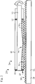
Fig. 2 , the high-lift device 24 is driven between a retracted and an extended position by alinear drive device 26. - The
linear drive device 26 comprises afirst member 28 that extends in a longitudinal direction. Thefirst member 28 has a plurality of engagingteeth 30. Thefirst member 28 can be atoothed rack 32. Thefirst member 28 is coupled to the high-lift device 24. - The
linear drive device 26 comprises asecond member 34. Thesecond member 34 can be moved relative to thefirst member 28 along the longitudinal direction. Thesecond member 34 is coupled to thewing 14. - The
second member 34 has a plurality of engagingmembers 36. The engagingmembers 34 can be shifted between a fully extended position and a fully retracted position. In the fully extended position, the engagingmembers 36 mesh with the engagingteeth 30, whereas in the fully retracted position the engagingmembers 36 are able to pass the engagingteeth 30 along the longitudinal direction. - The
second member 34 includes asupport member 38. Thesupport member 38 is configured to individually support the engagingmembers 36. In the present example, thesupport member 38 is formed by ahousing 40. - The
second member 34 comprises acam shaft 42. Thecam shaft 42 is supported in a rotating manner, preferably by thehousing 40. Thesecond member 34 may include one ormore bearings 43 for supporting thecam shaft 42. - The
cam shaft 42 has acontrol cam portion 44. Thecontrol cam portion 44 sequentially engages with the engagingmembers 36 upon rotation of thecam shaft 42. As indicated inFig. 2 , upon rotation of thecam shaft 42 in a clockwise direction, thecontrol cam portion 44 engages with the engagingmembers 36 in sequence from right to left, thereby pushing the engagingmembers 36 into the fully extended position. - The engaging
members 36 extend and retract in a wave-like pattern and as a result force thefirst member 28 along its longitudinal direction, for example to the left. - Referring to
Fig. 3 , a variant of thelinear drive device 26 is described only insofar as it differs from the embodiment ofFig. 2 . In this variant, the engagingmembers 36 are formed on a flexible sheet member 39. The flexible sheet member 39 can be a metal sheet, for example. The flexible sheet member 39 is flexible in the sense that the flexible sheet member 39 is reversibly deformed upon rotation of thecam shaft 42 by thecontrol cam portion 44, so that as a result the engagingmembers 36 are moved between the fully extended and fully retracted position. The flexible sheet member 39 can perform the function of a leaf spring such that the pushing of the engagingmembers 36 is caused by thecontrol cam portion 44, whereas the retraction is caused by the elastic tension of the flexible sheet member 39. - Referring to
Fig. 4 to Fig. 8 , the configuration and function of thecam shaft 42 are described in more detail. - The
control cam portion 44 comprises a plurality ofcam segments 46. Eachcam segment 46 has acircular portion 48. Thecircular portion 48 makes up the majority of the respective cam segment's 46 circumference. Thecircular portion 48 has a radius that allows the corresponding engagingmember 36 to be moved into its fully retracted position. - Each
cam segment 46 includes acontrol cam 50. Thecontrol cam 50 makes up the remainder of the cam segment's 46 circumference. Thecontrol cam 50 is configured such that, upon rotation of thecam segment 46, thecontrol cam 50 pushes the respective engagingmember 36 from the fully retracted position into the fully extended position. - As depicted in particular in
Fig. 4 to Fig. 6 thecam segments 46 are arranged on thecam shaft 42 such that neighboringcam segments 46 are offset by a certain offset angle θ. The offset angle θ is preferably measured between the lines through the largest radial extent of thecam segment 46 that cross in the center of thecam shaft 42, as illustrated inFig. 6 . -
Fig. 7 andFig. 8 illustrate more closely the action of asingle cam segment 46. - Each
control cam 50 includes three functional sections. A firstfunctional section 52 is the section that upon rotation of thecam shaft 46 makes initial contact with the engagingmember 36 and pushes it. A secondfunctional section 54 is the section which supports the engagingmember 36 in the fully extended position for a small part of the rotation of thecam shaft 42. A thirdfunctional section 56 is the section that recedes back upon rotation of thecam shaft 46 so that the engagingmember 36 may disengage from the engagingteeth 30. Disengaging may be caused by the engagingteeth 30 pushing the engagingmember 36 due to the longitudinal movement of thefirst member 28 or an elastic spring force generated by the flexible sheet member 39. - As shown in
Fig. 7 , thecam shaft 42 turns clockwise. Thefirst member 28 may move into the drawing layer. If thecam shaft 42 turns counter-clockwise, the motion of thefirst member 28 is also reversed. - Initially in step I, the
cam segment 46 makes contact with the engagingmember 36 by means of the firstfunctional section 52. As a result, the engagingmember 36 is pushed out of the fully retracted position towards thefirst member 28 and the driving force is transmitted from thecam shaft 42 to thefirst member 28. - In step II, the
cam segment 46 has moved on so that the secondfunctional section 54 keeps the engaging ember in the fully extended position, in which the engagingmember 36 and the engagingteeth 30 are meshing. - In steps III and IV, the
cam segment 46 has rotated further and the thirdfunctional section 56 is contacting the engagingmember 36. Thus, the engagingmember 36 is prevented from being fully pushed into the fully retracted position by forces acting on thefirst member 28. Albeit the thirdfunctional section 56 allows the engagingmember 36 to recede from full engagement with the engagingteeth 30. As a result, a force acting on thefirst member 28 may be transmitted via the engagingmember 36 to the cam shaft. - In steps V to VIII, the
cam segment 46 may contact the engagingmember 36 with itscircular portion 48. In this configuration, no force is transmitted from thecam shaft 42 to thefirst member 28. - Taking into account that the steps I to VIII are performed by each
individual cam segment 46, the entirelinear drive device 26 has no backlash and is self-locking. Furthermore, the offset angle θ influences the reduction ratio. The smaller θ is, the larger is the reduction ratio. - It should be noted that while the
control cam portion 44 was previously described as being formed from separatediscreet cam segments 46, the size of thecam segments 46 may be chosen so small that for practical purposes thecam segments 46 and thecam portion 44 are continuous or without step-like features betweenadjacent cam segments 46. -
Fig. 8 depicts the stroke ofadjacent cam segments 46 over their rotational angle. They are offset by the offset angle θ. The zero stroke or dwell corresponds to thecircular portion 48, the rising portion corresponds to the firstfunctional section 50, the upper flat portion at maximum stroke corresponds to the secondfunctional portion 52 and the falling portion corresponds to the thirdfunctional section 52. - It should be noted that while the curves in
Fig. 8 are depicted having a linear characteristic over the rotational angle, this need not be the case. Depending on various parameters for the drive, other characteristics are possible. - Referring to
Fig. 9 andFig. 10 , another embodiment of alinear drive device 26 is described insofar as it differs from the previously described embodiment. - The
linear drive device 26 comprises afirst member 28 that extends in a longitudinal direction. Thefirst member 28 has a plurality of engagingteeth 30. The engagingteeth 30 are configured as circumferential teeth. - The
linear drive device 26 comprises asecond member 34. Thesecond member 34 can be moved relative to thefirst member 28 along the longitudinal direction. - The
second member 34 has a plurality of engagingmembers 36. The engagingmembers 36 are arranged circumferentially and preferably surround thefirst member 28, as depicted in particular inFig. 10 . - The
second member 34 includes asupport member 38. Thesupport member 38 is configured to individually support the engagingmembers 36. In the present example, thesupport member 38 takes the form of a bushing. - The
second member 34 comprises acam shaft 42. Thecam shaft 42 is supported in a rotating manner, preferably by a housing. The housing is omitted inFig. 9 andFig. 10 so as to allow view of the mechanism. - The
cam shaft 42 is configured as a hollow shaft. Thecam shaft 42 has acontrol cam portion 44 arranged on its inner circumferential surface. Thecontrol cam portion 44 functions as previously described with reference toFig. 4 to Fig. 8 . - As a result, the engaging
members 36 extend and retract in a wave-like pattern and force thefirst member 28 along its longitudinal direction, for example to the left. - Referring to
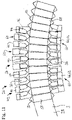
Fig. 11 , a variant of thelinear drive device 26 is described only insofar as it differs from the embodiment ofFig. 9 andFig. 10 . - In this variant, the
first member 28 is configured in a circular arc shape. The engagingteeth 30 are arranged on individualfirst member segments 58. Similarly, thesecond member 34 is configured as a plurality of individualsecond member segments 60. - Each
second member segment 60 includes a cam shaft segment 62 of thecam shaft 42, a support member segment of the support member 38 (not depicted for sake of a better view), and part of the engagingmembers 36. The whole configuration is kept together by means of a housing (again not depicted for better view). - In order to improve linear drives on aircraft with regards to backlash, gear reduction, self-lock capability, load transfer and wear, the invention provides a linear drive device (26) that has a first member (28) with engaging teeth (30), such as a tooth rack (34) and a second member (34) which functions as a drive unit. The second member (34) includes a plurality of movable teeth (36) that are actuated by a cam shaft (42). The cam shaft (42) has a control cam portion (44) that is shaped such that the movable teeth (36) perform a wave-like motion that forces the first member (28) along its longitudinal direction relative to the second member (34).
-
- 10
- aircraft
- 12
- fuselage
- 14
- wing
- 16
- turbine engine
- 18
- horizontal tail plane (HTP)
- 20
- vertical tail plane (VTP)
- 22
- control surface
- 24
- high-lift device
- 26
- linear drive device
- 28
- first member
- 30
- engaging teeth
- 32
- toothed rack
- 34
- second member
- 36
- engaging members
- 38
- support member
- 39
- flexible sheet member
- 40
- housing
- 42
- cam shaft
- 43
- bearing
- 44
- control cam portion
- 46
- cam segment
- 48
- circular portion
- 50
- control cam
- 52
- first functional section
- 54
- second functional section
- 56
- third functional section
- 58
- first member segment
- 60
- second member segment
- 62
- cam shaft segment
- θ
- offset angle
Claims (15)
- A linear drive device (26), comprising a first member (28) , the first member (28) extending in a longitudinal direction and having a plurality of engaging teeth (30), and a second member (34) configured to be movable relative to the first member (28) in the longitudinal direction, the second member (34) including:- a plurality of engaging members (36) being supported so as to be movable between a fully extended position, in which the respective engaging member (36) fully engages a pair of engaging teeth (30), and a fully retracted position, in which the respective engaging member (36) is disengaged from the first member (28) such that the engaging member (36) is movable along the longitudinal direction without encountering an engaging tooth (30);- a rotatable cam shaft (42) having a control cam portion (44), the control cam portion (44) being configured so as to, upon rotation of the cam shaft (42), sequentially shift the engaging members (36) thereby causing a linear motion of the second member (34) relative to the first member (28) along the longitudinal direction.
- The linear drive device (26) according to claim 1, wherein the engaging members (36) are configured in a linear arrangement that is aligned parallel to the longitudinal direction; and/or wherein the engaging members (36) are configured in a circular arrangement around the first member (28).
- The linear drive device (26) according to any of the preceding claims, wherein at least one engaging member (36) is integrally formed with a membrane member (39), the membrane member (39) being deformable by the control cam portion (44) so that the engaging members (36) are shiftable between the fully retracted and fully engaged positions.
- The linear drive device (26) according to any of the preceding claims, wherein at least one engaging member (36) has an engaging portion that is arranged to contact the first member (28), and the engaging portion engages the first member (28) in a planar manner.
- The linear drive device (26) according to any of the preceding claims, wherein at least one engaging member (36) has a cam contact portion that is arranged opposite of the engaging portion and arranged to contact the cam portion.
- The linear drive device (26) according to any of the preceding claims, wherein at least one engaging member (36) is formed as a rectangular solid member or as a pin-like member; or wherein at least one engaging member (36) is formed as a circular arc shaped solid member.
- The linear drive device (26) according to any of the preceding claims, wherein the second member (34) supports the cam shaft (42) and/or the engaging members (36).
- The linear drive device (26) according to any of the preceding claims, wherein the second member (34) comprises a support member (38) having a plurality of openings, and the engaging members (36) are arranged in the openings so as to be slidable between the fully extended and fully retracted positions.
- The linear drive device (26) according to any of the preceding claims, wherein the cam shaft (42) is configured as a massive shaft and the control cam portion (44) is disposed on the outer circumferential surface of the cam shaft (42); or wherein the cam shaft (42) is configured as a hollow shaft and the control cam portion (44) is disposed on the inner circumferential surface of the cam shaft (42).
- The linear drive device (26) according to any of the preceding claims, wherein the cam shaft (42) comprises a plurality of cam segments (46) and each cam segment (46) includes a different part of the control cam portion (44).
- The linear drive device (26) according to claim 10, wherein the cam segments (46) are rotationally offset by an offset angle (θ) in a progressive manner along the axial direction of the cam shaft (42), so as to generate a wave-like motion of the engaging members (36) along the longitudinal direction.
- The linear drive device (26) according to claim 10 or 11, wherein the cam shaft (42) is configured as an articulated shaft and each cam segment (46) forms an articulated portion of the articulated shaft.
- A drive arrangement for a wing (14) of an aircraft (10) comprising a high-lift device (24) and/or a control surface (22), and a linear drive device (26) according to any the preceding claims, wherein the linear drive device (26) is configured for driving the high-lift device (24) and/or the control surface (22) between a fully retracted and a fully extended position, wherein the first member (28) is attached to the high-lift device (24) and/or control surface (22) and the second member (34) is attachable to the wing (14).
- A wing (14) for an aircraft (10) comprising a drive arrangement according to claim 13.
- An aircraft (10) comprising a linear drive device (26) according to any of the claims 1 to 12, or a drive arrangement according to claim 13, or a wing (14) according to claim 14.
Applications Claiming Priority (1)
| Application Number | Priority Date | Filing Date | Title |
|---|---|---|---|
| DE102021101487 | 2021-01-25 |
Publications (2)
| Publication Number | Publication Date |
|---|---|
| EP4033122A1 true EP4033122A1 (en) | 2022-07-27 |
| EP4033122B1 EP4033122B1 (en) | 2024-08-07 |
Family
ID=82101441
Family Applications (1)
| Application Number | Title | Priority Date | Filing Date |
|---|---|---|---|
| EP22150475.6A Active EP4033122B1 (en) | 2021-01-25 | 2022-01-06 | Drive arrangement for an aircraft |
Country Status (2)
| Country | Link |
|---|---|
| US (1) | US11731755B2 (en) |
| EP (1) | EP4033122B1 (en) |
Cited By (1)
| Publication number | Priority date | Publication date | Assignee | Title |
|---|---|---|---|---|
| AT526603A4 (en) * | 2023-01-03 | 2024-05-15 | Gear Systems Gmbh | LINEAR ACTUATOR |
Families Citing this family (1)
| Publication number | Priority date | Publication date | Assignee | Title |
|---|---|---|---|---|
| EP4450326B1 (en) * | 2023-04-20 | 2026-02-18 | IMS Gear SE & Co. KGaA | Linear drive, longitudinal adjustment unit with such a linear drive |
Citations (5)
| Publication number | Priority date | Publication date | Assignee | Title |
|---|---|---|---|---|
| EP0612935A1 (en) * | 1993-02-24 | 1994-08-31 | Teijin Seiki Company Limited | Mechanism for transforming rotational into linear motion |
| US20090205451A1 (en) * | 2006-09-08 | 2009-08-20 | Wittenstein Ag | Gearing |
| EP3299278A1 (en) * | 2016-09-23 | 2018-03-28 | Airbus Operations GmbH | A slat track device for an aircraft wing |
| US10550924B2 (en) * | 2012-03-30 | 2020-02-04 | Wittenstein Ag | Transmission |
| EP3748195A1 (en) * | 2019-06-04 | 2020-12-09 | IMS Gear SE & Co. KGaA | Linear actuator, longitudinal adjustment device of a seat and motor vehicle |
Family Cites Families (4)
| Publication number | Priority date | Publication date | Assignee | Title |
|---|---|---|---|---|
| DE3136552A1 (en) * | 1981-09-15 | 1983-03-31 | FAG Kugelfischer Georg Schäfer & Co, 8720 Schweinfurt | Linear drive for a slide |
| DE102011051514A1 (en) * | 2011-07-01 | 2013-01-03 | Wittenstein Ag | transmission |
| DE102016204133A1 (en) * | 2016-03-14 | 2017-09-14 | Zf Friedrichshafen Ag | Linear actuator |
| DE102019129662A1 (en) * | 2019-11-04 | 2021-05-06 | Wittenstein Se | Coaxial gear |
-
2022
- 2022-01-06 EP EP22150475.6A patent/EP4033122B1/en active Active
- 2022-01-21 US US17/580,765 patent/US11731755B2/en active Active
Patent Citations (5)
| Publication number | Priority date | Publication date | Assignee | Title |
|---|---|---|---|---|
| EP0612935A1 (en) * | 1993-02-24 | 1994-08-31 | Teijin Seiki Company Limited | Mechanism for transforming rotational into linear motion |
| US20090205451A1 (en) * | 2006-09-08 | 2009-08-20 | Wittenstein Ag | Gearing |
| US10550924B2 (en) * | 2012-03-30 | 2020-02-04 | Wittenstein Ag | Transmission |
| EP3299278A1 (en) * | 2016-09-23 | 2018-03-28 | Airbus Operations GmbH | A slat track device for an aircraft wing |
| EP3748195A1 (en) * | 2019-06-04 | 2020-12-09 | IMS Gear SE & Co. KGaA | Linear actuator, longitudinal adjustment device of a seat and motor vehicle |
Cited By (2)
| Publication number | Priority date | Publication date | Assignee | Title |
|---|---|---|---|---|
| AT526603A4 (en) * | 2023-01-03 | 2024-05-15 | Gear Systems Gmbh | LINEAR ACTUATOR |
| AT526603B1 (en) * | 2023-01-03 | 2024-05-15 | Gear Systems Gmbh | LINEAR ACTUATOR |
Also Published As
| Publication number | Publication date |
|---|---|
| US20220234724A1 (en) | 2022-07-28 |
| US11731755B2 (en) | 2023-08-22 |
| EP4033122B1 (en) | 2024-08-07 |
Similar Documents
| Publication | Publication Date | Title |
|---|---|---|
| EP4033122B1 (en) | Drive arrangement for an aircraft | |
| US5106349A (en) | Differential unit | |
| US8272833B2 (en) | Turboprop with a variable-pitch propeller | |
| RU2619742C2 (en) | Differential lock with small stroke length and with large length of locking links | |
| US6314835B1 (en) | Piezo-electric drive arrangement for a harmonic drive transmission | |
| EP2261114A2 (en) | Pitch change actuation system for a counter-rotating propeller | |
| EP3076045B1 (en) | Backlash correction system for compound planetary gear train | |
| CN110925382A (en) | Unit type wave gear device | |
| US11639747B2 (en) | Linear actuator | |
| EP4032803A1 (en) | A linear drive device for an aircraft, a drive arrangement and an aircraft having such a linear drive device | |
| WO2020070039A1 (en) | Drive assembly comprising two shafts connected by drive means | |
| US20240209929A1 (en) | Strain wave drive | |
| US3696686A (en) | Control apparatus | |
| US3724759A (en) | Drive mechanism | |
| GB2555931A (en) | Continuously variable ratio transmission | |
| US12553504B2 (en) | Strain wave drive | |
| US12529413B2 (en) | Actuators | |
| CN111271424B (en) | Actuating mechanism with satellite roller screw mechanism | |
| US20170350473A1 (en) | Transmission with nested gear configuration | |
| EP4283164B1 (en) | Harmonic drive transmission with split flexspline | |
| US20150083061A1 (en) | Cam phaser with eccentric lantern gear component | |
| CN108698689B (en) | Reduction gear with input/output rotation commutation | |
| EP1715142A1 (en) | Apparatus for variable valve timing adjustment of an internal combustion engine | |
| EP4350173B1 (en) | Rotary mechanical transmission | |
| EP4400745A1 (en) | Epicyclic gear system |
Legal Events
| Date | Code | Title | Description |
|---|---|---|---|
| PUAI | Public reference made under article 153(3) epc to a published international application that has entered the european phase |
Free format text: ORIGINAL CODE: 0009012 |
|
| STAA | Information on the status of an ep patent application or granted ep patent |
Free format text: STATUS: THE APPLICATION HAS BEEN PUBLISHED |
|
| AK | Designated contracting states |
Kind code of ref document: A1 Designated state(s): AL AT BE BG CH CY CZ DE DK EE ES FI FR GB GR HR HU IE IS IT LI LT LU LV MC MK MT NL NO PL PT RO RS SE SI SK SM TR |
|
| STAA | Information on the status of an ep patent application or granted ep patent |
Free format text: STATUS: REQUEST FOR EXAMINATION WAS MADE |
|
| 17P | Request for examination filed |
Effective date: 20230127 |
|
| RBV | Designated contracting states (corrected) |
Designated state(s): AL AT BE BG CH CY CZ DE DK EE ES FI FR GB GR HR HU IE IS IT LI LT LU LV MC MK MT NL NO PL PT RO RS SE SI SK SM TR |
|
| STAA | Information on the status of an ep patent application or granted ep patent |
Free format text: STATUS: EXAMINATION IS IN PROGRESS |
|
| 17Q | First examination report despatched |
Effective date: 20231106 |
|
| GRAP | Despatch of communication of intention to grant a patent |
Free format text: ORIGINAL CODE: EPIDOSNIGR1 |
|
| STAA | Information on the status of an ep patent application or granted ep patent |
Free format text: STATUS: GRANT OF PATENT IS INTENDED |
|
| INTG | Intention to grant announced |
Effective date: 20240419 |
|
| GRAS | Grant fee paid |
Free format text: ORIGINAL CODE: EPIDOSNIGR3 |
|
| GRAA | (expected) grant |
Free format text: ORIGINAL CODE: 0009210 |
|
| STAA | Information on the status of an ep patent application or granted ep patent |
Free format text: STATUS: THE PATENT HAS BEEN GRANTED |
|
| AK | Designated contracting states |
Kind code of ref document: B1 Designated state(s): AL AT BE BG CH CY CZ DE DK EE ES FI FR GB GR HR HU IE IS IT LI LT LU LV MC MK MT NL NO PL PT RO RS SE SI SK SM TR |
|
| REG | Reference to a national code |
Ref country code: GB Ref legal event code: FG4D |
|
| REG | Reference to a national code |
Ref country code: CH Ref legal event code: EP |
|
| REG | Reference to a national code |
Ref country code: IE Ref legal event code: FG4D |
|
| REG | Reference to a national code |
Ref country code: DE Ref legal event code: R096 Ref document number: 602022005032 Country of ref document: DE |
|
| REG | Reference to a national code |
Ref country code: LT Ref legal event code: MG9D |
|
| REG | Reference to a national code |
Ref country code: NL Ref legal event code: MP Effective date: 20240807 |
|
| PG25 | Lapsed in a contracting state [announced via postgrant information from national office to epo] |
Ref country code: NO Free format text: LAPSE BECAUSE OF FAILURE TO SUBMIT A TRANSLATION OF THE DESCRIPTION OR TO PAY THE FEE WITHIN THE PRESCRIBED TIME-LIMIT Effective date: 20241107 |
|
| REG | Reference to a national code |
Ref country code: AT Ref legal event code: MK05 Ref document number: 1711257 Country of ref document: AT Kind code of ref document: T Effective date: 20240807 |
|
| PG25 | Lapsed in a contracting state [announced via postgrant information from national office to epo] |
Ref country code: PT Free format text: LAPSE BECAUSE OF FAILURE TO SUBMIT A TRANSLATION OF THE DESCRIPTION OR TO PAY THE FEE WITHIN THE PRESCRIBED TIME-LIMIT Effective date: 20241209 Ref country code: FI Free format text: LAPSE BECAUSE OF FAILURE TO SUBMIT A TRANSLATION OF THE DESCRIPTION OR TO PAY THE FEE WITHIN THE PRESCRIBED TIME-LIMIT Effective date: 20240807 Ref country code: NL Free format text: LAPSE BECAUSE OF FAILURE TO SUBMIT A TRANSLATION OF THE DESCRIPTION OR TO PAY THE FEE WITHIN THE PRESCRIBED TIME-LIMIT Effective date: 20240807 Ref country code: PL Free format text: LAPSE BECAUSE OF FAILURE TO SUBMIT A TRANSLATION OF THE DESCRIPTION OR TO PAY THE FEE WITHIN THE PRESCRIBED TIME-LIMIT Effective date: 20240807 Ref country code: GR Free format text: LAPSE BECAUSE OF FAILURE TO SUBMIT A TRANSLATION OF THE DESCRIPTION OR TO PAY THE FEE WITHIN THE PRESCRIBED TIME-LIMIT Effective date: 20241108 |
|
| PG25 | Lapsed in a contracting state [announced via postgrant information from national office to epo] |
Ref country code: BG Free format text: LAPSE BECAUSE OF FAILURE TO SUBMIT A TRANSLATION OF THE DESCRIPTION OR TO PAY THE FEE WITHIN THE PRESCRIBED TIME-LIMIT Effective date: 20240807 |
|
| PG25 | Lapsed in a contracting state [announced via postgrant information from national office to epo] |
Ref country code: LV Free format text: LAPSE BECAUSE OF FAILURE TO SUBMIT A TRANSLATION OF THE DESCRIPTION OR TO PAY THE FEE WITHIN THE PRESCRIBED TIME-LIMIT Effective date: 20240807 |
|
| PG25 | Lapsed in a contracting state [announced via postgrant information from national office to epo] |
Ref country code: IS Free format text: LAPSE BECAUSE OF FAILURE TO SUBMIT A TRANSLATION OF THE DESCRIPTION OR TO PAY THE FEE WITHIN THE PRESCRIBED TIME-LIMIT Effective date: 20241207 Ref country code: AT Free format text: LAPSE BECAUSE OF FAILURE TO SUBMIT A TRANSLATION OF THE DESCRIPTION OR TO PAY THE FEE WITHIN THE PRESCRIBED TIME-LIMIT Effective date: 20240807 |
|
| PG25 | Lapsed in a contracting state [announced via postgrant information from national office to epo] |
Ref country code: HR Free format text: LAPSE BECAUSE OF FAILURE TO SUBMIT A TRANSLATION OF THE DESCRIPTION OR TO PAY THE FEE WITHIN THE PRESCRIBED TIME-LIMIT Effective date: 20240807 |
|
| PG25 | Lapsed in a contracting state [announced via postgrant information from national office to epo] |
Ref country code: ES Free format text: LAPSE BECAUSE OF FAILURE TO SUBMIT A TRANSLATION OF THE DESCRIPTION OR TO PAY THE FEE WITHIN THE PRESCRIBED TIME-LIMIT Effective date: 20240807 Ref country code: RS Free format text: LAPSE BECAUSE OF FAILURE TO SUBMIT A TRANSLATION OF THE DESCRIPTION OR TO PAY THE FEE WITHIN THE PRESCRIBED TIME-LIMIT Effective date: 20241107 |
|
| PG25 | Lapsed in a contracting state [announced via postgrant information from national office to epo] |
Ref country code: RS Free format text: LAPSE BECAUSE OF FAILURE TO SUBMIT A TRANSLATION OF THE DESCRIPTION OR TO PAY THE FEE WITHIN THE PRESCRIBED TIME-LIMIT Effective date: 20241107 Ref country code: PT Free format text: LAPSE BECAUSE OF FAILURE TO SUBMIT A TRANSLATION OF THE DESCRIPTION OR TO PAY THE FEE WITHIN THE PRESCRIBED TIME-LIMIT Effective date: 20241209 Ref country code: PL Free format text: LAPSE BECAUSE OF FAILURE TO SUBMIT A TRANSLATION OF THE DESCRIPTION OR TO PAY THE FEE WITHIN THE PRESCRIBED TIME-LIMIT Effective date: 20240807 Ref country code: NO Free format text: LAPSE BECAUSE OF FAILURE TO SUBMIT A TRANSLATION OF THE DESCRIPTION OR TO PAY THE FEE WITHIN THE PRESCRIBED TIME-LIMIT Effective date: 20241107 Ref country code: NL Free format text: LAPSE BECAUSE OF FAILURE TO SUBMIT A TRANSLATION OF THE DESCRIPTION OR TO PAY THE FEE WITHIN THE PRESCRIBED TIME-LIMIT Effective date: 20240807 Ref country code: LV Free format text: LAPSE BECAUSE OF FAILURE TO SUBMIT A TRANSLATION OF THE DESCRIPTION OR TO PAY THE FEE WITHIN THE PRESCRIBED TIME-LIMIT Effective date: 20240807 Ref country code: IS Free format text: LAPSE BECAUSE OF FAILURE TO SUBMIT A TRANSLATION OF THE DESCRIPTION OR TO PAY THE FEE WITHIN THE PRESCRIBED TIME-LIMIT Effective date: 20241207 Ref country code: HR Free format text: LAPSE BECAUSE OF FAILURE TO SUBMIT A TRANSLATION OF THE DESCRIPTION OR TO PAY THE FEE WITHIN THE PRESCRIBED TIME-LIMIT Effective date: 20240807 Ref country code: GR Free format text: LAPSE BECAUSE OF FAILURE TO SUBMIT A TRANSLATION OF THE DESCRIPTION OR TO PAY THE FEE WITHIN THE PRESCRIBED TIME-LIMIT Effective date: 20241108 Ref country code: FI Free format text: LAPSE BECAUSE OF FAILURE TO SUBMIT A TRANSLATION OF THE DESCRIPTION OR TO PAY THE FEE WITHIN THE PRESCRIBED TIME-LIMIT Effective date: 20240807 Ref country code: ES Free format text: LAPSE BECAUSE OF FAILURE TO SUBMIT A TRANSLATION OF THE DESCRIPTION OR TO PAY THE FEE WITHIN THE PRESCRIBED TIME-LIMIT Effective date: 20240807 Ref country code: BG Free format text: LAPSE BECAUSE OF FAILURE TO SUBMIT A TRANSLATION OF THE DESCRIPTION OR TO PAY THE FEE WITHIN THE PRESCRIBED TIME-LIMIT Effective date: 20240807 Ref country code: AT Free format text: LAPSE BECAUSE OF FAILURE TO SUBMIT A TRANSLATION OF THE DESCRIPTION OR TO PAY THE FEE WITHIN THE PRESCRIBED TIME-LIMIT Effective date: 20240807 |
|
| PG25 | Lapsed in a contracting state [announced via postgrant information from national office to epo] |
Ref country code: SM Free format text: LAPSE BECAUSE OF FAILURE TO SUBMIT A TRANSLATION OF THE DESCRIPTION OR TO PAY THE FEE WITHIN THE PRESCRIBED TIME-LIMIT Effective date: 20240807 Ref country code: DK Free format text: LAPSE BECAUSE OF FAILURE TO SUBMIT A TRANSLATION OF THE DESCRIPTION OR TO PAY THE FEE WITHIN THE PRESCRIBED TIME-LIMIT Effective date: 20240807 |
|
| PG25 | Lapsed in a contracting state [announced via postgrant information from national office to epo] |
Ref country code: EE Free format text: LAPSE BECAUSE OF FAILURE TO SUBMIT A TRANSLATION OF THE DESCRIPTION OR TO PAY THE FEE WITHIN THE PRESCRIBED TIME-LIMIT Effective date: 20240807 |
|
| PG25 | Lapsed in a contracting state [announced via postgrant information from national office to epo] |
Ref country code: CZ Free format text: LAPSE BECAUSE OF FAILURE TO SUBMIT A TRANSLATION OF THE DESCRIPTION OR TO PAY THE FEE WITHIN THE PRESCRIBED TIME-LIMIT Effective date: 20240807 |
|
| PG25 | Lapsed in a contracting state [announced via postgrant information from national office to epo] |
Ref country code: SK Free format text: LAPSE BECAUSE OF FAILURE TO SUBMIT A TRANSLATION OF THE DESCRIPTION OR TO PAY THE FEE WITHIN THE PRESCRIBED TIME-LIMIT Effective date: 20240807 |
|
| REG | Reference to a national code |
Ref country code: DE Ref legal event code: R097 Ref document number: 602022005032 Country of ref document: DE |
|
| PLBE | No opposition filed within time limit |
Free format text: ORIGINAL CODE: 0009261 |
|
| STAA | Information on the status of an ep patent application or granted ep patent |
Free format text: STATUS: NO OPPOSITION FILED WITHIN TIME LIMIT |
|
| 26N | No opposition filed |
Effective date: 20250508 |
|
| REG | Reference to a national code |
Ref country code: CH Ref legal event code: PL |
|
| PG25 | Lapsed in a contracting state [announced via postgrant information from national office to epo] |
Ref country code: SE Free format text: LAPSE BECAUSE OF FAILURE TO SUBMIT A TRANSLATION OF THE DESCRIPTION OR TO PAY THE FEE WITHIN THE PRESCRIBED TIME-LIMIT Effective date: 20240807 |
|
| PG25 | Lapsed in a contracting state [announced via postgrant information from national office to epo] |
Ref country code: MC Free format text: LAPSE BECAUSE OF FAILURE TO SUBMIT A TRANSLATION OF THE DESCRIPTION OR TO PAY THE FEE WITHIN THE PRESCRIBED TIME-LIMIT Effective date: 20240807 Ref country code: LU Free format text: LAPSE BECAUSE OF NON-PAYMENT OF DUE FEES Effective date: 20250106 |
|
| PG25 | Lapsed in a contracting state [announced via postgrant information from national office to epo] |
Ref country code: CH Free format text: LAPSE BECAUSE OF NON-PAYMENT OF DUE FEES Effective date: 20250131 |
|
| PG25 | Lapsed in a contracting state [announced via postgrant information from national office to epo] |
Ref country code: IE Free format text: LAPSE BECAUSE OF NON-PAYMENT OF DUE FEES Effective date: 20250106 |
|
| PG25 | Lapsed in a contracting state [announced via postgrant information from national office to epo] |
Ref country code: IT Free format text: LAPSE BECAUSE OF FAILURE TO SUBMIT A TRANSLATION OF THE DESCRIPTION OR TO PAY THE FEE WITHIN THE PRESCRIBED TIME-LIMIT Effective date: 20240807 |
|
| PGFP | Annual fee paid to national office [announced via postgrant information from national office to epo] |
Ref country code: GB Payment date: 20260123 Year of fee payment: 5 |
|
| PGFP | Annual fee paid to national office [announced via postgrant information from national office to epo] |
Ref country code: DE Payment date: 20260121 Year of fee payment: 5 |
|
| PG25 | Lapsed in a contracting state [announced via postgrant information from national office to epo] |
Ref country code: RO Free format text: LAPSE BECAUSE OF FAILURE TO SUBMIT A TRANSLATION OF THE DESCRIPTION OR TO PAY THE FEE WITHIN THE PRESCRIBED TIME-LIMIT Effective date: 20240807 |
|
| PGFP | Annual fee paid to national office [announced via postgrant information from national office to epo] |
Ref country code: BE Payment date: 20260121 Year of fee payment: 5 |
|
| PGFP | Annual fee paid to national office [announced via postgrant information from national office to epo] |
Ref country code: FR Payment date: 20260123 Year of fee payment: 5 |