EP4033088A1 - Fuel nozzle seal removal tool - Google Patents
Fuel nozzle seal removal tool Download PDFInfo
- Publication number
- EP4033088A1 EP4033088A1 EP22153192.4A EP22153192A EP4033088A1 EP 4033088 A1 EP4033088 A1 EP 4033088A1 EP 22153192 A EP22153192 A EP 22153192A EP 4033088 A1 EP4033088 A1 EP 4033088A1
- Authority
- EP
- European Patent Office
- Prior art keywords
- punch
- block
- holder
- fuel injector
- apertures
- Prior art date
- Legal status (The legal status is an assumption and is not a legal conclusion. Google has not performed a legal analysis and makes no representation as to the accuracy of the status listed.)
- Granted
Links
Images


Classifications
-
- B—PERFORMING OPERATIONS; TRANSPORTING
- B25—HAND TOOLS; PORTABLE POWER-DRIVEN TOOLS; MANIPULATORS
- B25B—TOOLS OR BENCH DEVICES NOT OTHERWISE PROVIDED FOR, FOR FASTENING, CONNECTING, DISENGAGING, OR HOLDING
- B25B27/00—Hand tools, specially adapted for fitting together or separating parts or objects whether or not involving some deformation, not otherwise provided for
- B25B27/0028—Tools for removing or installing seals
-
- B—PERFORMING OPERATIONS; TRANSPORTING
- B23—MACHINE TOOLS; METAL-WORKING NOT OTHERWISE PROVIDED FOR
- B23P—METAL-WORKING NOT OTHERWISE PROVIDED FOR; COMBINED OPERATIONS; UNIVERSAL MACHINE TOOLS
- B23P19/00—Machines for simply fitting together or separating metal parts or objects, or metal and non-metal parts, whether or not involving some deformation; Tools or devices therefor so far as not provided for in other classes
- B23P19/04—Machines for simply fitting together or separating metal parts or objects, or metal and non-metal parts, whether or not involving some deformation; Tools or devices therefor so far as not provided for in other classes for assembling or disassembling parts
-
- B—PERFORMING OPERATIONS; TRANSPORTING
- B23—MACHINE TOOLS; METAL-WORKING NOT OTHERWISE PROVIDED FOR
- B23P—METAL-WORKING NOT OTHERWISE PROVIDED FOR; COMBINED OPERATIONS; UNIVERSAL MACHINE TOOLS
- B23P19/00—Machines for simply fitting together or separating metal parts or objects, or metal and non-metal parts, whether or not involving some deformation; Tools or devices therefor so far as not provided for in other classes
- B23P19/04—Machines for simply fitting together or separating metal parts or objects, or metal and non-metal parts, whether or not involving some deformation; Tools or devices therefor so far as not provided for in other classes for assembling or disassembling parts
- B23P19/042—Machines for simply fitting together or separating metal parts or objects, or metal and non-metal parts, whether or not involving some deformation; Tools or devices therefor so far as not provided for in other classes for assembling or disassembling parts specially adapted for combustion engines
-
- B—PERFORMING OPERATIONS; TRANSPORTING
- B23—MACHINE TOOLS; METAL-WORKING NOT OTHERWISE PROVIDED FOR
- B23P—METAL-WORKING NOT OTHERWISE PROVIDED FOR; COMBINED OPERATIONS; UNIVERSAL MACHINE TOOLS
- B23P19/00—Machines for simply fitting together or separating metal parts or objects, or metal and non-metal parts, whether or not involving some deformation; Tools or devices therefor so far as not provided for in other classes
- B23P19/04—Machines for simply fitting together or separating metal parts or objects, or metal and non-metal parts, whether or not involving some deformation; Tools or devices therefor so far as not provided for in other classes for assembling or disassembling parts
- B23P19/08—Machines for placing washers, circlips, or the like on bolts or other members
- B23P19/084—Machines for placing washers, circlips, or the like on bolts or other members for placing resilient or flexible rings, e.g. O-rings, circlips
-
- F—MECHANICAL ENGINEERING; LIGHTING; HEATING; WEAPONS; BLASTING
- F02—COMBUSTION ENGINES; HOT-GAS OR COMBUSTION-PRODUCT ENGINE PLANTS
- F02M—SUPPLYING COMBUSTION ENGINES IN GENERAL WITH COMBUSTIBLE MIXTURES OR CONSTITUENTS THEREOF
- F02M61/00—Fuel-injectors not provided for in groups F02M39/00 - F02M57/00 or F02M67/00
- F02M61/14—Arrangements of injectors with respect to engines; Mounting of injectors
-
- F—MECHANICAL ENGINEERING; LIGHTING; HEATING; WEAPONS; BLASTING
- F02—COMBUSTION ENGINES; HOT-GAS OR COMBUSTION-PRODUCT ENGINE PLANTS
- F02M—SUPPLYING COMBUSTION ENGINES IN GENERAL WITH COMBUSTIBLE MIXTURES OR CONSTITUENTS THEREOF
- F02M61/00—Fuel-injectors not provided for in groups F02M39/00 - F02M57/00 or F02M67/00
- F02M61/16—Details not provided for in, or of interest apart from, the apparatus of groups F02M61/02 - F02M61/14
- F02M61/168—Assembling; Disassembling; Manufacturing; Adjusting
-
- B—PERFORMING OPERATIONS; TRANSPORTING
- B05—SPRAYING OR ATOMISING IN GENERAL; APPLYING FLUENT MATERIALS TO SURFACES, IN GENERAL
- B05B—SPRAYING APPARATUS; ATOMISING APPARATUS; NOZZLES
- B05B15/00—Details of spraying plant or spraying apparatus not otherwise provided for; Accessories
- B05B15/60—Arrangements for mounting, supporting or holding spraying apparatus
- B05B15/65—Mounting arrangements for fluid connection of the spraying apparatus or its outlets to flow conduits
-
- F—MECHANICAL ENGINEERING; LIGHTING; HEATING; WEAPONS; BLASTING
- F02—COMBUSTION ENGINES; HOT-GAS OR COMBUSTION-PRODUCT ENGINE PLANTS
- F02M—SUPPLYING COMBUSTION ENGINES IN GENERAL WITH COMBUSTIBLE MIXTURES OR CONSTITUENTS THEREOF
- F02M2200/00—Details of fuel-injection apparatus, not otherwise provided for
- F02M2200/16—Sealing of fuel injection apparatus not otherwise provided for
-
- F—MECHANICAL ENGINEERING; LIGHTING; HEATING; WEAPONS; BLASTING
- F02—COMBUSTION ENGINES; HOT-GAS OR COMBUSTION-PRODUCT ENGINE PLANTS
- F02M—SUPPLYING COMBUSTION ENGINES IN GENERAL WITH COMBUSTIBLE MIXTURES OR CONSTITUENTS THEREOF
- F02M2200/00—Details of fuel-injection apparatus, not otherwise provided for
- F02M2200/85—Mounting of fuel injection apparatus
- F02M2200/852—Mounting of fuel injection apparatus provisions for mounting the fuel injection apparatus in a certain orientation, e.g. markings or notches
Definitions
- the present disclosure relates to fuel nozzles, and more particularly to seals for fuel nozzles and their removal.
- a c-seal is used to seal between fuel injectors in gas turbine engines and the high pressure engine case.
- soft materials such as copper, brass, or the like
- the c-seal can be removed from the fuel injector during maintenance using traditional techniques with relative ease.
- the traditional technique involves using a hammer and chisel method to remove the c-seal.
- removal of the c-seal from the fuel injector without damaging the fuel injector can be dependent on the skill and steady hands of the individual removing the c-seal. It is not therefore certain that damage to the injector can be avoided.
- a system comprises a holder including a mounting feature configured to mount to a flange of a fuel injector and a block including a mounting feature configured to mount to a side of the flange that is opposite from the holder.
- the system includes a punch configured to pass through at least one punch aperture in the block.
- the punch aperture is configured to guide a tip of the punch into position to deform a c-seal seated in a seal channel of the flange.
- the tip of the punch is shaped to fit within the seal channel and the punch can include an enlarged end opposite the tip configured for driving the punch into the seal channel.
- the at least one punch aperture can be a plurality of punch apertures, each punch aperture configured to guide the tip of the punch into position to deform a c-seal seated in a seal channel of the flange.
- Each punch aperture in the plurality of punch apertures can include a bushing seated therein. The bushing can be configured to facilitate guided movement of the punch through the respective aperture in the block.
- the block can also include a plurality of pin apertures therethrough for receiving pins to engage with the holder through mounting apertures in the flange of the fuel injector.
- the punch apertures can alternate with the pin apertures in a circumferential pattern around the block, and there can be three punch apertures and four pin apertures.
- the block can define a u-shape about a main channel configured to accommodate a feed arm of the fuel injector.
- the holder can define a u-shape about a main channel, such that the holder and block are mounted to the flange with the u-shape of the holder opening in an opposite direction from that of the block.
- a method includes removing a fuel injector from a system, seating the fuel injector in a holder, affixing a block to the fuel injector and holder, inserting a punch into one of the punch apertures, striking the punch with a force to deform a c-seal engaged with the fuel injector, removing the block from the holder and fuel injector, and removing the c-seal from the fuel injector.
- Inserting the punch into one of the punch apertures and striking the punch can be repeated for each of the punch apertures.
- Affixing the block to the fuel injector and holder can include seating a respective pin aperture of the block onto a respective pin passing from the holder through flange of the fuel injector.
- Affixing the block can include accommodating a feed arm of the fuel injector in the main channel.
- Affixing the block can include affixing the block so the holder and block are mounted to the flange with the u-shape of the holder opening in an opposite direction from that of the block.
- a system 100 e.g. a system for removing a seal from a fuel injector 102, can include a holder 104, where the holder 104 includes a mounting feature 106 configured to mount to a first side 107 of a flange 108 of the fuel injector 102.
- the holder 104 can also include a block 110 including a mounting feature 112 configured to mount to a second side 109 of the flange 108 opposite of the first side 107 of the flange 108 from the holder 104.
- a punch 114 can be configured to pass through a punch aperture 116 in the block 110.
- the punch aperture 116 can be configured to guide a tip 118 of the punch 114 into position to deform a c-seal 120 seated in a seal channel 122.
- the tip 118 of the punch 114 can be shaped and sized to fit within the punch aperture 116, for example, the tip 118 can be flat relative to a longitudinal axis A of the punch 114.
- the punch 114 can include an enlarged end 124 opposite the tip 118 configured for driving the punch 114 into the seal channel 122 with any suitable force.
- Deforming the c-seal 120 can include changing a shape of the seal 122 to break the sealed connection with the seal channel 122, or deforming the seal 120 can include breaking the seal 120 into pieces to allow for removal of seal 120 from the seal channel 122 (e.g. as shown in Fig. 5 ).
- the block 110 can include a plurality of punch apertures 116, and each punch aperture 116 can include a bushing 126 seated therein configured to facilitate guided movement of the punch 114 through the respective aperture 116.
- the bushings can be configured to align the tip 118 with the seal channel 122, however, the bushings 126 can be configured to assist in aligning any shaped tip 118 as the tip 118 passes through the punch aperture 116.
- the block 110 can also include a plurality of pin apertures 128 for receiving pins 130 to engage with the holder 104 through corresponding mounting apertures in the flange 108 of the fuel injector 102.
- the punch apertures 116 can alternate with the pin apertures 128 in a circumferential pattern around the block 110, and in embodiments, the block 110 can include three punch apertures 116 and four pin apertures 128, however any suitable number can be used.
- the block 110 can define a u-shape about a main channel 134 configured to accommodate a feed arm 136 of the fuel injector 102.
- the holder 104 can also define a u-shape about a main channel 134, such that the holder 104 and block 110 can be mounted to the flange 108 with the u-shape of the holder 104 opening in an opposite direction from that of the block 110.
- a method 200 can include, removing 202 a fuel injector (e.g. from a gas turbine engine), seating 204 the fuel injector in a holder, affixing 206 a block to the fuel injector and holder, inserting 208 a punch into one of the punch apertures, striking 210 the punch with a force to deform a c-seal engaged with the fuel injector, removing 212 the block from the holder and fuel injector, and removing 214 the c-seal from the fuel injector.
- a fuel injector e.g. from a gas turbine engine
- Inserting 208 the punch into one of the punch apertures and striking 2010 the punch can be repeated for each of the punch apertures.
- Affixing 206 the block to the fuel injector and holder can include seating a respective pin aperture of the block onto a respective pin passing from the holder through flange of the fuel injector.
- Affixing 206 the block can include accommodating a feed arm of the fuel injector in the main channel.
- Affixing 206 the block can include affixing the block so the holder and block are mounted to the flange with the u-shape of the holder opening in an opposite direction from that of the block.
- C-seals for fuel nozzles can be made of different materials depending on the type and/or model of the respective fuel injector.
- certain c-seals may be made of a harder material and may be designed for a tighter press fit than other nozzle seals.
- a c-seal is removed using a "hammer and chisel" method.
- harder material and tighter fit can make removal of the seal using this method difficult to do without damaging the nozzle flange. Results of depend on operators' skillset as it is common to slip and damage the flange or seal channel.
Landscapes
- Engineering & Computer Science (AREA)
- Mechanical Engineering (AREA)
- Chemical & Material Sciences (AREA)
- Combustion & Propulsion (AREA)
- General Engineering & Computer Science (AREA)
- Manufacturing & Machinery (AREA)
- Fuel-Injection Apparatus (AREA)
Abstract
Description
- The present disclosure relates to fuel nozzles, and more particularly to seals for fuel nozzles and their removal.
- A c-seal is used to seal between fuel injectors in gas turbine engines and the high pressure engine case. When soft materials are used for the c-seal, such as copper, brass, or the like, the c-seal can be removed from the fuel injector during maintenance using traditional techniques with relative ease. The traditional technique involves using a hammer and chisel method to remove the c-seal. However, if a harder material is used for the c-seal, removal of the c-seal from the fuel injector without damaging the fuel injector can be dependent on the skill and steady hands of the individual removing the c-seal. It is not therefore certain that damage to the injector can be avoided.
- The conventional techniques have been considered satisfactory for their intended purpose. However, there is an ever present need for improved systems and methods for simplified and damage free removal of fuel nozzle seals. This disclosure provides a solution for this need.
- A system comprises a holder including a mounting feature configured to mount to a flange of a fuel injector and a block including a mounting feature configured to mount to a side of the flange that is opposite from the holder. The system includes a punch configured to pass through at least one punch aperture in the block. The punch aperture is configured to guide a tip of the punch into position to deform a c-seal seated in a seal channel of the flange. The tip of the punch is shaped to fit within the seal channel and the punch can include an enlarged end opposite the tip configured for driving the punch into the seal channel.
- The at least one punch aperture can be a plurality of punch apertures, each punch aperture configured to guide the tip of the punch into position to deform a c-seal seated in a seal channel of the flange. Each punch aperture in the plurality of punch apertures can include a bushing seated therein. The bushing can be configured to facilitate guided movement of the punch through the respective aperture in the block. The block can also include a plurality of pin apertures therethrough for receiving pins to engage with the holder through mounting apertures in the flange of the fuel injector.
- The punch apertures can alternate with the pin apertures in a circumferential pattern around the block, and there can be three punch apertures and four pin apertures. The block can define a u-shape about a main channel configured to accommodate a feed arm of the fuel injector. The holder can define a u-shape about a main channel, such that the holder and block are mounted to the flange with the u-shape of the holder opening in an opposite direction from that of the block.
- A method includes removing a fuel injector from a system, seating the fuel injector in a holder, affixing a block to the fuel injector and holder, inserting a punch into one of the punch apertures, striking the punch with a force to deform a c-seal engaged with the fuel injector, removing the block from the holder and fuel injector, and removing the c-seal from the fuel injector.
- Inserting the punch into one of the punch apertures and striking the punch can be repeated for each of the punch apertures. Affixing the block to the fuel injector and holder can include seating a respective pin aperture of the block onto a respective pin passing from the holder through flange of the fuel injector. Affixing the block can include accommodating a feed arm of the fuel injector in the main channel. Affixing the block can include affixing the block so the holder and block are mounted to the flange with the u-shape of the holder opening in an opposite direction from that of the block.
- These and other features of the systems and methods of the subject disclosure will become more readily apparent to those skilled in the art from the following detailed description taken in conjunction with the drawings.
- So that those skilled in the art to which the subject disclosure appertains will readily understand how to make and use the devices and methods of the subject disclosure without undue experimentation, embodiments thereof will be described in detail herein below with reference to certain figures, wherein:
-
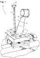
Fig. 1 is a schematic perspective view of an embodiment of a fuel nozzle seal removal system constructed in accordance with the present disclosure, showing a fuel injector mounted in the system; -
Fig. 2 is an exploded perspective view of the system ofFig. 1 ; -
Fig. 3 is a schematic partial cross sectional view of a portion of the system ofFig. 1 ; -
Fig. 4 is a schematic enlarged view of the system ofFig. 3 , showing a punch deforming a seal in a seal channel in the system ofFig. 1 ; -
Fig. 5 is a top down view of the system ofFig. 1 showing a deformed seal; -
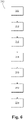
Fig. 6 is a schematic box diagram of a method. - Reference will now be made to the drawings wherein like reference numerals identify similar structural features or aspects of the subject disclosure. For purposes of explanation and illustration, and not limitation, a partial view of an embodiment of a system in accordance with the disclosure is shown in
Fig. 1 and is designated generally byreference character 100. Other embodiments of systems in accordance with the disclosure, or aspects thereof, are provided inFigs. 2-6 , as will be described. The systems and methods described herein can be used for removing seals from fuel injectors with reduced variability in the results based on skill of the individual performing maintenance. - A
system 100, e.g. a system for removing a seal from afuel injector 102, can include a holder 104, where the holder 104 includes amounting feature 106 configured to mount to afirst side 107 of aflange 108 of thefuel injector 102. The holder 104 can also include ablock 110 including amounting feature 112 configured to mount to asecond side 109 of theflange 108 opposite of thefirst side 107 of theflange 108 from the holder 104. - A
punch 114 can be configured to pass through apunch aperture 116 in theblock 110. Thepunch aperture 116 can be configured to guide atip 118 of thepunch 114 into position to deform a c-seal 120 seated in aseal channel 122. For example, thetip 118 of thepunch 114 can be shaped and sized to fit within thepunch aperture 116, for example, thetip 118 can be flat relative to a longitudinal axis A of thepunch 114. Thepunch 114 can include an enlargedend 124 opposite thetip 118 configured for driving thepunch 114 into theseal channel 122 with any suitable force. Deforming the c-seal 120 can include changing a shape of theseal 122 to break the sealed connection with theseal channel 122, or deforming theseal 120 can include breaking theseal 120 into pieces to allow for removal ofseal 120 from the seal channel 122 (e.g. as shown inFig. 5 ). - In embodiments, the
block 110 can include a plurality ofpunch apertures 116, and eachpunch aperture 116 can include a bushing 126 seated therein configured to facilitate guided movement of thepunch 114 through therespective aperture 116. For example, if thetip 118 is flat relative to a longitudinal axis A of thepunch 114, the bushings can be configured to align thetip 118 with theseal channel 122, however, thebushings 126 can be configured to assist in aligning anyshaped tip 118 as thetip 118 passes through thepunch aperture 116. Theblock 110 can also include a plurality ofpin apertures 128 for receivingpins 130 to engage with the holder 104 through corresponding mounting apertures in theflange 108 of thefuel injector 102. - The
punch apertures 116 can alternate with thepin apertures 128 in a circumferential pattern around theblock 110, and in embodiments, theblock 110 can include threepunch apertures 116 and fourpin apertures 128, however any suitable number can be used. Theblock 110 can define a u-shape about amain channel 134 configured to accommodate afeed arm 136 of thefuel injector 102. The holder 104 can also define a u-shape about amain channel 134, such that the holder 104 andblock 110 can be mounted to theflange 108 with the u-shape of the holder 104 opening in an opposite direction from that of theblock 110. - A
method 200 can include, removing 202 a fuel injector (e.g. from a gas turbine engine), seating 204 the fuel injector in a holder, affixing 206 a block to the fuel injector and holder, inserting 208 a punch into one of the punch apertures, striking 210 the punch with a force to deform a c-seal engaged with the fuel injector, removing 212 the block from the holder and fuel injector, and removing 214 the c-seal from the fuel injector. - Inserting 208 the punch into one of the punch apertures and striking 2010 the punch can be repeated for each of the punch apertures. Affixing 206 the block to the fuel injector and holder can include seating a respective pin aperture of the block onto a respective pin passing from the holder through flange of the fuel injector. Affixing 206 the block can include accommodating a feed arm of the fuel injector in the main channel. Affixing 206 the block can include affixing the block so the holder and block are mounted to the flange with the u-shape of the holder opening in an opposite direction from that of the block.
- C-seals for fuel nozzles can be made of different materials depending on the type and/or model of the respective fuel injector. For example, certain c-seals may be made of a harder material and may be designed for a tighter press fit than other nozzle seals. Conventionally, a c-seal is removed using a "hammer and chisel" method. However, harder material and tighter fit can make removal of the seal using this method difficult to do without damaging the nozzle flange. Results of depend on operators' skillset as it is common to slip and damage the flange or seal channel. The methods and systems of the present disclosure, as described above and shown in the drawings thus provide for better control of the deformation of the seal and improved ergonomics of the "hammer and chisel" process so that the seal can be removed without damage to the nozzle. While the apparatus and methods of the subject disclosure have been shown and described, those skilled in the art will readily appreciate that changes and/or modifications may be made thereto without departing from the scope of the invention as defined by the claims.
Claims (15)
- A system comprising:a holder (104) including a mounting feature (106) configured to mount to a flange (108) of a fuel injector (102);a block (110) including a mounting feature configured to mount to a side (109) of the flange that is opposite from the holder;at least one punch aperture (116) defined in the block; anda punch (114) configured to pass through the at least one punch aperture in the block, wherein the punch aperture is configured to guide a tip (118) of the punch into position to deform a c-seal (120) seated in a seal channel (122) of the flange.
- The system as recited in claim 1, wherein the at least one punch aperture (116) is a plurality of punch apertures, each punch aperture configured to guide the tip (118) of the punch into position to deform a c-seal (120) seated in a seal channel (122) of the flange.
- The system as recited in claim 2, wherein each punch aperture in the plurality of punch apertures includes a bushing (126) seated therein, wherein the bushing is configured to facilitate guided movement of the punch through the respective aperture in the block.
- The system as recited in any preceding claim, wherein the block includes a plurality of pin apertures (128) therethrough for receiving pins (130) to engage with holder through mounting apertures in the flange of the fuel injector.
- The system as recited in claim 4, wherein the block includes a plurality of pin apertures therethrough for receiving pins to engage with the holder through mounting apertures in the flange of the fuel injector, wherein the punch apertures alternate with the pin apertures in a circumferential pattern around the block.
- The system as recited in claim 5, wherein the block includes three punch apertures and four pin apertures.
- The system as recited in any preceding claim, wherein the block defines a u-shape about a main channel (134) configured to accommodate a feed arm (136) of the fuel injector.
- The system as recited in claim 7, wherein the holder defines a u-shape about the main channel, wherein the holder and block are mounted to the flange with the u-shape of the holder opening in an opposite direction from that of the block.
- The system as recited in any preceding claim, wherein the tip (118) of the punch is shaped to fit within the seal channel (122).
- The system as recited in claim 9, wherein the punch includes an enlarged end (124) opposite the tip.
- A method comprising:removing a fuel injector (102) from a system;seating the fuel injector in a holder (104);affixing a block (110) to the fuel injector and holder, wherein the block includes a plurality of punch apertures (116) therethrough;inserting a punch (114) into one of the punch apertures;striking the punch with a force to deform a c-seal (120) engaged with the fuel injector;removing the block from the holder and fuel injector; andremoving the c-seal from the fuel injector.
- The method as recited in claim 11, wherein inserting the punch into one of the punch apertures and striking the punch are repeated for each of the punch apertures.
- The method as recited in claim 11 or 12, wherein affixing the block to the fuel injector and holder includes seating a respective pin aperture (128) of the block onto a respective pin (130) passing from the holder through flange of the fuel injector.
- The method as recited in claim 11, 12 or 13, wherein the block defines a u-shape about a main channel (134), wherein affixing the block includes accommodating a feed arm (136) of the fuel injector in the main channel.
- The method as recited in claim 14, wherein the holder defines a u-shape about the main channel, wherein affixing the block includes affixing the block so the holder and block are mounted to the flange with the u-shape of the holder opening in an opposite direction from that of the block.
Applications Claiming Priority (1)
| Application Number | Priority Date | Filing Date | Title |
|---|---|---|---|
| US17/157,904 US11285571B1 (en) | 2021-01-25 | 2021-01-25 | Fuel nozzle seal removal tool |
Publications (2)
| Publication Number | Publication Date |
|---|---|
| EP4033088A1 true EP4033088A1 (en) | 2022-07-27 |
| EP4033088B1 EP4033088B1 (en) | 2026-05-06 |
Family
ID=80034967
Family Applications (1)
| Application Number | Title | Priority Date | Filing Date |
|---|---|---|---|
| EP22153192.4A Active EP4033088B1 (en) | 2021-01-25 | 2022-01-25 | Fuel nozzle seal removal tool |
Country Status (2)
| Country | Link |
|---|---|
| US (1) | US11285571B1 (en) |
| EP (1) | EP4033088B1 (en) |
Families Citing this family (1)
| Publication number | Priority date | Publication date | Assignee | Title |
|---|---|---|---|---|
| JP2025128516A (en) * | 2024-02-22 | 2025-09-03 | 三菱重工コンプレッサ株式会社 | Seal removal tool, seal removal method, and seal part |
Citations (6)
| Publication number | Priority date | Publication date | Assignee | Title |
|---|---|---|---|---|
| US3564696A (en) * | 1968-05-29 | 1971-02-23 | Joseph F Shepanski | Apparatus for removing oil or grease seals |
| US3909916A (en) * | 1974-06-21 | 1975-10-07 | Cummins Engine Co Inc | Component removal tool |
| US4213235A (en) * | 1978-10-13 | 1980-07-22 | Gary Kemmerling | Seal remover |
| US5784783A (en) * | 1996-04-18 | 1998-07-28 | Carpenter; Donald L. | Method of removing an injector sleeve |
| US6065198A (en) * | 1998-12-02 | 2000-05-23 | Daimlerchrysler Corporation | Tools for installing an oil seal |
| DE102008056876A1 (en) * | 2008-11-12 | 2010-05-20 | Man Diesel Se | Extraction device for valve seat ring in diesel engine of ship, has hydraulic device applying axial traction force on spindle in extraction direction, and spindle guided at support in extraction direction against surrounding area of ring |
Family Cites Families (19)
| Publication number | Priority date | Publication date | Assignee | Title |
|---|---|---|---|---|
| US3014271A (en) * | 1957-07-18 | 1961-12-26 | Leonard J Englund | Tool for removing seals |
| US3084423A (en) * | 1959-05-04 | 1963-04-09 | Gail D Fullerton | Bearing seal installer tool |
| US3286335A (en) * | 1964-03-23 | 1966-11-22 | Pietra Dante C Di | Method for replacing a seal in a support housing |
| US3809046A (en) * | 1972-09-01 | 1974-05-07 | K Line Ind Inc | Valve guide stabilizing and sealing insert |
| FR2244599B1 (en) | 1973-09-26 | 1977-03-11 | France Etat | |
| US4483137A (en) * | 1981-07-30 | 1984-11-20 | Solar Turbines, Incorporated | Gas turbine engine construction and operation |
| US4466240A (en) * | 1981-10-26 | 1984-08-21 | United Technologies Corporation | Fuel nozzle for gas turbine engine with external and internal removal capability |
| US4813120A (en) * | 1987-09-10 | 1989-03-21 | Fournier James L | Method for removing O-rings and backup rings from annular indentations |
| US5692282A (en) * | 1995-12-22 | 1997-12-02 | Baca; Frank M. | Seal puller |
| US5771696A (en) * | 1996-10-21 | 1998-06-30 | General Electric Company | Internal manifold fuel injection assembly for gas turbine |
| CA2214137C (en) * | 1997-08-28 | 2001-07-24 | Roland Goguen | Tool kit for working wheel bearings |
| ES2295164T3 (en) * | 2000-03-22 | 2008-04-16 | Siemens Aktiengesellschaft | PROCEDURE TO REMOVE A MEANS OF OBTURATION. |
| US6543113B1 (en) * | 2000-04-18 | 2003-04-08 | Cummins Engine Company, Inc. | Tooling components for crankshaft seal removal and installation |
| US7703287B2 (en) * | 2006-10-31 | 2010-04-27 | Delavan Inc | Dynamic sealing assembly to accommodate differential thermal growth of fuel injector components |
| US7849575B2 (en) * | 2007-09-20 | 2010-12-14 | Schlem Products, Inc. | Seal removal tool and method |
| FR2935777B1 (en) * | 2008-09-09 | 2013-03-08 | Snecma | TURBOMACHINE COMBUSTION CHAMBER |
| GB0918169D0 (en) * | 2009-10-19 | 2009-12-02 | Rolls Royce Plc | Fuel injector mounting system |
| US20120054997A1 (en) * | 2010-03-09 | 2012-03-08 | International Engine Intellectual Property Company | Process and system for disassembling fuel injector |
| US9814340B2 (en) | 2014-09-26 | 2017-11-14 | Hangers Plus, Llc | Hanger |
-
2021
- 2021-01-25 US US17/157,904 patent/US11285571B1/en active Active
-
2022
- 2022-01-25 EP EP22153192.4A patent/EP4033088B1/en active Active
Patent Citations (6)
| Publication number | Priority date | Publication date | Assignee | Title |
|---|---|---|---|---|
| US3564696A (en) * | 1968-05-29 | 1971-02-23 | Joseph F Shepanski | Apparatus for removing oil or grease seals |
| US3909916A (en) * | 1974-06-21 | 1975-10-07 | Cummins Engine Co Inc | Component removal tool |
| US4213235A (en) * | 1978-10-13 | 1980-07-22 | Gary Kemmerling | Seal remover |
| US5784783A (en) * | 1996-04-18 | 1998-07-28 | Carpenter; Donald L. | Method of removing an injector sleeve |
| US6065198A (en) * | 1998-12-02 | 2000-05-23 | Daimlerchrysler Corporation | Tools for installing an oil seal |
| DE102008056876A1 (en) * | 2008-11-12 | 2010-05-20 | Man Diesel Se | Extraction device for valve seat ring in diesel engine of ship, has hydraulic device applying axial traction force on spindle in extraction direction, and spindle guided at support in extraction direction against surrounding area of ring |
Also Published As
| Publication number | Publication date |
|---|---|
| US11285571B1 (en) | 2022-03-29 |
| EP4033088B1 (en) | 2026-05-06 |
Similar Documents
| Publication | Publication Date | Title |
|---|---|---|
| US20200006868A1 (en) | Insulation displacement termination (idt) for applying multiple electrical wire gauge sizes simultaneously or individually to electrical connectors, stamped and formed strip terminal products, and assembly fixtures thereof | |
| EP4033088B1 (en) | Fuel nozzle seal removal tool | |
| US20190039112A1 (en) | Pressing device and pressing method for metal plate | |
| US5417532A (en) | Casting repair apparatus and method | |
| EP3194106B1 (en) | Apparatus for welding together bar-shaped conductors | |
| US6305201B1 (en) | Method and apparatus for forming unobstructed holes in hollow hydroformed metal parts | |
| KR960013906B1 (en) | Needle mounting device for warp knitting machine | |
| KR19990087517A (en) | How to mount the baffle on the tubular member | |
| US11646510B2 (en) | Shielding electrical terminal with knurling on inner contact walls | |
| US20240238951A1 (en) | Tool for removing a seal ring from a spark plug | |
| EP0343178A1 (en) | Device for mounting contact parts with their leads into plug housings | |
| US7566843B2 (en) | Wire inserting method and wire inserting apparatus in wire discharge processing | |
| EP0261457B1 (en) | Pin retention method and apparatus | |
| US6678945B2 (en) | Backside pin removal tool | |
| US20190020127A1 (en) | Insulation displacement termination (idt) for mass termination of multiple electrical wiregauge sizes and in termination of multiple wire gauge sizes to strip terminal products | |
| CN108808405B (en) | Device and method for assembling plug housing provided with sealing gasket | |
| CN106475739B (en) | The nozzle member and its manufacturing method of fuel injector | |
| EP2361729B1 (en) | Method to remove a nose part of an injection nozzle from a cylinder head | |
| US20240033857A1 (en) | System and method for cracking a connecting rod | |
| US6108902A (en) | Contact pin header connector repair method and repair fixture | |
| JP2018079531A (en) | Knock pin driving assist jig and knock pin driving method | |
| CN218253744U (en) | Subsea connector handle | |
| JP3028459B2 (en) | Multi-step processing equipment | |
| US12466010B2 (en) | Broken bolt removal template for cylinder head | |
| CN112828825A (en) | Pin splitter applied to narrow space and use method thereof |
Legal Events
| Date | Code | Title | Description |
|---|---|---|---|
| PUAI | Public reference made under article 153(3) epc to a published international application that has entered the european phase |
Free format text: ORIGINAL CODE: 0009012 |
|
| STAA | Information on the status of an ep patent application or granted ep patent |
Free format text: STATUS: THE APPLICATION HAS BEEN PUBLISHED |
|
| AK | Designated contracting states |
Kind code of ref document: A1 Designated state(s): AL AT BE BG CH CY CZ DE DK EE ES FI FR GB GR HR HU IE IS IT LI LT LU LV MC MK MT NL NO PL PT RO RS SE SI SK SM TR |
|
| STAA | Information on the status of an ep patent application or granted ep patent |
Free format text: STATUS: REQUEST FOR EXAMINATION WAS MADE |
|
| 17P | Request for examination filed |
Effective date: 20230127 |
|
| RBV | Designated contracting states (corrected) |
Designated state(s): AL AT BE BG CH CY CZ DE DK EE ES FI FR GB GR HR HU IE IS IT LI LT LU LV MC MK MT NL NO PL PT RO RS SE SI SK SM TR |
|
| P01 | Opt-out of the competence of the unified patent court (upc) registered |
Effective date: 20230922 |
|
| STAA | Information on the status of an ep patent application or granted ep patent |
Free format text: STATUS: EXAMINATION IS IN PROGRESS |
|
| 17Q | First examination report despatched |
Effective date: 20240412 |
|
| GRAP | Despatch of communication of intention to grant a patent |
Free format text: ORIGINAL CODE: EPIDOSNIGR1 |
|
| STAA | Information on the status of an ep patent application or granted ep patent |
Free format text: STATUS: GRANT OF PATENT IS INTENDED |
|
| INTG | Intention to grant announced |
Effective date: 20251222 |
|
| GRAS | Grant fee paid |
Free format text: ORIGINAL CODE: EPIDOSNIGR3 |
|
| GRAA | (expected) grant |
Free format text: ORIGINAL CODE: 0009210 |
|
| STAA | Information on the status of an ep patent application or granted ep patent |
Free format text: STATUS: THE PATENT HAS BEEN GRANTED |
|
| AK | Designated contracting states |
Kind code of ref document: B1 Designated state(s): AL AT BE BG CH CY CZ DE DK EE ES FI FR GB GR HR HU IE IS IT LI LT LU LV MC MK MT NL NO PL PT RO RS SE SI SK SM TR |
|
| REG | Reference to a national code |
Ref country code: CH Ref legal event code: F10 Free format text: ST27 STATUS EVENT CODE: U-0-0-F10-F00 (AS PROVIDED BY THE NATIONAL OFFICE) Effective date: 20260506 Ref country code: GB Ref legal event code: FG4D |
|
| REG | Reference to a national code |
Ref country code: DE Ref legal event code: R096 Ref document number: 602022035969 Country of ref document: DE |
|
| REG | Reference to a national code |
Ref country code: IE Ref legal event code: FG4D |