EP4033024A1 - Chemistry dispensing assembly for a laundry appliance - Google Patents
Chemistry dispensing assembly for a laundry appliance Download PDFInfo
- Publication number
- EP4033024A1 EP4033024A1 EP22152811.0A EP22152811A EP4033024A1 EP 4033024 A1 EP4033024 A1 EP 4033024A1 EP 22152811 A EP22152811 A EP 22152811A EP 4033024 A1 EP4033024 A1 EP 4033024A1
- Authority
- EP
- European Patent Office
- Prior art keywords
- laundry
- chemistry
- fluid
- mixing
- mixing channel
- Prior art date
- Legal status (The legal status is an assumption and is not a legal conclusion. Google has not performed a legal analysis and makes no representation as to the accuracy of the status listed.)
- Withdrawn
Links
Images



Classifications
-
- D—TEXTILES; PAPER
- D06—TREATMENT OF TEXTILES OR THE LIKE; LAUNDERING; FLEXIBLE MATERIALS NOT OTHERWISE PROVIDED FOR
- D06F—LAUNDERING, DRYING, IRONING, PRESSING OR FOLDING TEXTILE ARTICLES
- D06F39/00—Details of washing machines not specific to a single type of machines covered by groups D06F9/00 - D06F27/00
- D06F39/02—Devices for adding soap or other washing agents
- D06F39/028—Arrangements for selectively supplying water to detergent compartments
-
- D—TEXTILES; PAPER
- D06—TREATMENT OF TEXTILES OR THE LIKE; LAUNDERING; FLEXIBLE MATERIALS NOT OTHERWISE PROVIDED FOR
- D06F—LAUNDERING, DRYING, IRONING, PRESSING OR FOLDING TEXTILE ARTICLES
- D06F39/00—Details of washing machines not specific to a single type of machines covered by groups D06F9/00 - D06F27/00
- D06F39/02—Devices for adding soap or other washing agents
- D06F39/022—Devices for adding soap or other washing agents in a liquid state
-
- B—PERFORMING OPERATIONS; TRANSPORTING
- B01—PHYSICAL OR CHEMICAL PROCESSES OR APPARATUS IN GENERAL
- B01F—MIXING, e.g. DISSOLVING, EMULSIFYING OR DISPERSING
- B01F23/00—Mixing according to the phases to be mixed, e.g. dispersing or emulsifying
- B01F23/40—Mixing liquids with liquids; Emulsifying
- B01F23/45—Mixing liquids with liquids; Emulsifying using flow mixing
- B01F23/451—Mixing liquids with liquids; Emulsifying using flow mixing by injecting one liquid into another
-
- B—PERFORMING OPERATIONS; TRANSPORTING
- B01—PHYSICAL OR CHEMICAL PROCESSES OR APPARATUS IN GENERAL
- B01F—MIXING, e.g. DISSOLVING, EMULSIFYING OR DISPERSING
- B01F25/00—Flow mixers; Mixers for falling materials, e.g. solid particles
- B01F25/10—Mixing by creating a vortex flow, e.g. by tangential introduction of flow components
- B01F25/103—Mixing by creating a vortex flow, e.g. by tangential introduction of flow components with additional mixing means other than vortex mixers, e.g. the vortex chamber being positioned in another mixing chamber
-
- B—PERFORMING OPERATIONS; TRANSPORTING
- B01—PHYSICAL OR CHEMICAL PROCESSES OR APPARATUS IN GENERAL
- B01F—MIXING, e.g. DISSOLVING, EMULSIFYING OR DISPERSING
- B01F25/00—Flow mixers; Mixers for falling materials, e.g. solid particles
- B01F25/40—Static mixers
- B01F25/42—Static mixers in which the mixing is affected by moving the components jointly in changing directions, e.g. in tubes provided with baffles or obstructions
- B01F25/421—Static mixers in which the mixing is affected by moving the components jointly in changing directions, e.g. in tubes provided with baffles or obstructions by moving the components in a convoluted or labyrinthine path
- B01F25/423—Static mixers in which the mixing is affected by moving the components jointly in changing directions, e.g. in tubes provided with baffles or obstructions by moving the components in a convoluted or labyrinthine path by means of elements placed in the receptacle for moving or guiding the components
- B01F25/4231—Static mixers in which the mixing is affected by moving the components jointly in changing directions, e.g. in tubes provided with baffles or obstructions by moving the components in a convoluted or labyrinthine path by means of elements placed in the receptacle for moving or guiding the components using baffles
-
- B—PERFORMING OPERATIONS; TRANSPORTING
- B01—PHYSICAL OR CHEMICAL PROCESSES OR APPARATUS IN GENERAL
- B01F—MIXING, e.g. DISSOLVING, EMULSIFYING OR DISPERSING
- B01F25/00—Flow mixers; Mixers for falling materials, e.g. solid particles
- B01F25/40—Static mixers
- B01F25/45—Mixers in which the materials to be mixed are pressed together through orifices or interstitial spaces, e.g. between beads
- B01F25/452—Mixers in which the materials to be mixed are pressed together through orifices or interstitial spaces, e.g. between beads characterised by elements provided with orifices or interstitial spaces
- B01F25/4521—Mixers in which the materials to be mixed are pressed together through orifices or interstitial spaces, e.g. between beads characterised by elements provided with orifices or interstitial spaces the components being pressed through orifices in elements, e.g. flat plates or cylinders, which obstruct the whole diameter of the tube
-
- D—TEXTILES; PAPER
- D06—TREATMENT OF TEXTILES OR THE LIKE; LAUNDERING; FLEXIBLE MATERIALS NOT OTHERWISE PROVIDED FOR
- D06F—LAUNDERING, DRYING, IRONING, PRESSING OR FOLDING TEXTILE ARTICLES
- D06F37/00—Details specific to washing machines covered by groups D06F21/00 - D06F25/00
- D06F37/26—Casings; Tubs
-
- B—PERFORMING OPERATIONS; TRANSPORTING
- B01—PHYSICAL OR CHEMICAL PROCESSES OR APPARATUS IN GENERAL
- B01F—MIXING, e.g. DISSOLVING, EMULSIFYING OR DISPERSING
- B01F2101/00—Mixing characterised by the nature of the mixed materials or by the application field
- B01F2101/4505—Mixing ingredients comprising detergents, soaps, for washing, e.g. washing machines
-
- B—PERFORMING OPERATIONS; TRANSPORTING
- B01—PHYSICAL OR CHEMICAL PROCESSES OR APPARATUS IN GENERAL
- B01F—MIXING, e.g. DISSOLVING, EMULSIFYING OR DISPERSING
- B01F2101/00—Mixing characterised by the nature of the mixed materials or by the application field
- B01F2101/48—Mixing water in water-taps with other ingredients, e.g. air, detergents or disinfectants
-
- D—TEXTILES; PAPER
- D06—TREATMENT OF TEXTILES OR THE LIKE; LAUNDERING; FLEXIBLE MATERIALS NOT OTHERWISE PROVIDED FOR
- D06F—LAUNDERING, DRYING, IRONING, PRESSING OR FOLDING TEXTILE ARTICLES
- D06F21/00—Washing machines with receptacles, e.g. perforated, having a rotary movement, e.g. oscillatory movement
- D06F21/06—Washing machines with receptacles, e.g. perforated, having a rotary movement, e.g. oscillatory movement about a vertical axis
-
- D—TEXTILES; PAPER
- D06—TREATMENT OF TEXTILES OR THE LIKE; LAUNDERING; FLEXIBLE MATERIALS NOT OTHERWISE PROVIDED FOR
- D06F—LAUNDERING, DRYING, IRONING, PRESSING OR FOLDING TEXTILE ARTICLES
- D06F23/00—Washing machines with receptacles, e.g. perforated, having a rotary movement, e.g. oscillatory movement, the receptacle serving both for washing and for centrifugally separating water from the laundry
- D06F23/04—Washing machines with receptacles, e.g. perforated, having a rotary movement, e.g. oscillatory movement, the receptacle serving both for washing and for centrifugally separating water from the laundry and rotating or oscillating about a vertical axis
-
- D—TEXTILES; PAPER
- D06—TREATMENT OF TEXTILES OR THE LIKE; LAUNDERING; FLEXIBLE MATERIALS NOT OTHERWISE PROVIDED FOR
- D06F—LAUNDERING, DRYING, IRONING, PRESSING OR FOLDING TEXTILE ARTICLES
- D06F39/00—Details of washing machines not specific to a single type of machines covered by groups D06F9/00 - D06F27/00
- D06F39/08—Liquid supply or discharge arrangements
- D06F39/088—Liquid supply arrangements
Definitions
- the chemistry mixing section 36 of the tub ring 38 is positioned above the treatment chamber 16 and below the mixing channel 28.
- the tub ring 38 includes the deflector 72 that is positioned adjacent to the plurality of apertures 50 to define the dispensing slot 74 that is below the chemistry mixing section 36.
- the flow path 34 delivers the fluid carrier 32 and the laundry chemistry 14 into the treatment chamber 16, and also serves to mix the fluid carrier 32 and the laundry chemistry 14 to form the processing fluid 58.
- the chemistry mixing section of the tub ring includes a plurality of apertures that are positioned to deliver the laundry chemistry and the fluid carrier to the treatment chamber.
- the mixing channel includes a mixing plate having a plurality of perforations and the laundry chemistry and the fluid carrier are directed downward through the plurality of perforations and toward the tub ring.
Landscapes
- Chemical & Material Sciences (AREA)
- Engineering & Computer Science (AREA)
- Textile Engineering (AREA)
- Chemical Kinetics & Catalysis (AREA)
- Dispersion Chemistry (AREA)
- Detail Structures Of Washing Machines And Dryers (AREA)
Abstract
Description
- The device disclosed herein is in the field of laundry appliances, and more specifically, a laundry appliance including a chemistry dispensing mechanism having a mixing channel positioned immediately below a chemistry dispenser for mixing laundry chemistry with a fluid carrier.
- According to one aspect of the present disclosure, a laundry appliance includes a treatment chamber for processing articles of laundry. A cartridge housing includes a removable laundry cartridge that dispenses a laundry chemistry to the treatment chamber. A mixing channel is positioned below the cartridge housing that receives the laundry chemistry dispensed from the removable laundry cartridge. A fluid assembly delivers a fluid carrier through a flow path that includes the mixing channel. The laundry chemistry and the fluid carrier are delivered to a chemistry mixing section of a tub ring positioned above the treatment chamber and below the mixing channel.
- According to another aspect of the present disclosure, a chemistry dispensing assembly for a laundry appliance includes a reservoir that dispenses a laundry chemistry to a treatment chamber. A mixing channel is positioned below the reservoir that receives the laundry chemistry dispensed from the reservoir. A fluid assembly delivers a fluid carrier through a flow path that includes the mixing channel. The mixing channel is defined between an underside of the reservoir and an upper surface of the mixing channel.
- According to yet another aspect of the present disclosure, a laundry appliance includes a rotating drum for processing articles of laundry. A cartridge housing includes a removable laundry cartridge that dispenses a laundry chemistry for delivery to the rotating drum. A mixing plate is positioned below the cartridge housing that defines a mixing channel. The mixing channel receives the laundry chemistry dispensed from the removable laundry cartridge. A fluid assembly delivers a fluid carrier through a flow path that includes the mixing channel. The mixing channel is defined between an underside of the removable laundry cartridge and an upper surface of the mixing plate. The laundry chemistry and the fluid carrier are delivered to a chemistry mixing section of a tub ring that is positioned above the rotating drum and below the mixing channel.
- These and other features, advantages, and objects of the present disclosure will be further understood and appreciated by those skilled in the art by reference to the following specification, claims, and appended drawings.
- In the drawings:
-
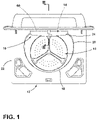
FIG. 1 is a top perspective view of a laundry appliance incorporating an aspect of the chemistry dispensing mechanism; -
FIG. 2 is a top plan view of an aspect of a mixing channel for the chemistry dispensing assembly; -
FIG. 3 is a cross-sectional view of the laundry appliance ofFIG. 1 taken along line III-III, and showing a relationship of a removable laundry cartridge with the mixing channel; -
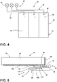
FIG. 4 is a schematic diagram illustrating a fluid assembly incorporated within an aspect of the chemistry dispensing mechanism; -
FIG. 5 is a cross-sectional schematic diagram illustrating an aspect of a mixing channel for the chemistry dispensing mechanism; -
FIG. 6 is another cross-sectional schematic diagram illustrating a configuration of the mixing channel for the chemistry dispensing mechanism; -
FIG. 7 is a schematic top plan view of a tub ring incorporating a chemistry mixing section for mixing laundry chemistry with a fluid carrier; -
FIG. 8 is a cross-sectional view of the tub ring ofFIG. 7 taken along line VIII-VIII and showing positioning of the plurality of apertures and the deflector of the tub ring; -
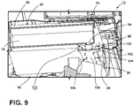
FIG. 9 is a cross-sectional view of an aspect of the chemistry dispensing mechanism incorporating a plurality of perforations within the mixing channel; and -
FIG. 10 is a cross-sectional schematic view of an aspect of the chemistry dispensing mechanism and incorporating a turbulence section that is defined between the mixing plate for the mixing channel and an underside of a removable laundry cartridge. - The components in the figures are not necessarily to scale, emphasis instead being placed upon illustrating the principles described herein.
- The present illustrated embodiments reside primarily in combinations of method steps and apparatus components related to a chemistry dispensing mechanism for a laundry appliance that delivers laundry chemistry using a fluid carrier. Accordingly, the apparatus components and method steps have been represented, where appropriate, by conventional symbols in the drawings, showing only those specific details that are pertinent to understanding the embodiments of the present disclosure so as not to obscure the disclosure with details that will be readily apparent to those of ordinary skill in the art having the benefit of the description herein. Further, like numerals in the description and drawings represent like elements.
- For purposes of description herein, the terms "upper," "lower," "right," "left," "rear," "front," "vertical," "horizontal," and derivatives thereof shall relate to the disclosure as oriented in
FIG. 1 . Unless stated otherwise, the term "front" shall refer to the surface of the element closer to an intended viewer, and the term "rear" shall refer to the surface of the element further from the intended viewer. However, it is to be understood that the disclosure may assume various alternative orientations, except where expressly specified to the contrary. It is also to be understood that the specific devices and processes illustrated in the attached drawings, and described in the following specification are simply exemplary embodiments of the inventive concepts defined in the appended claims. Hence, specific dimensions and other physical characteristics relating to the embodiments disclosed herein are not to be considered as limiting, unless the claims expressly state otherwise. - The terms "including," "comprises," "comprising," or any other variation thereof, are intended to cover a non-exclusive inclusion, such that a process, method, article, or apparatus that comprises a list of elements does not include only those elements but may include other elements not expressly listed or inherent to such process, method, article, or apparatus. An element proceeded by "comprises a ... " does not, without more constraints, preclude the existence of additional identical elements in the process, method, article, or apparatus that comprises the element.
- With reference to
FIGS. 1-8 ,reference numeral 10 generally refers to a chemistry dispensing mechanism that is incorporated within alaundry appliance 12, where thechemistry dispensing mechanism 10 disposes alaundry chemistry 14 from areservoir 60, typically incorporated within aremovable laundry cartridge 26, toward atreatment chamber 16 of thelaundry appliance 12. Thetreatment chamber 16 can take the form of a rotatingdrum 18 that is positioned within atub 20, that is in turn positioned within anouter cabinet 22. The rotatingdrum 18 can operate about a vertical axis or a horizontal axis, depending upon the configuration of theparticular appliance 12. According to various aspects of the device, thelaundry appliance 12 includes thetreatment chamber 16 for processing articles of laundry. Acartridge housing 24 includes aremovable laundry cartridge 26 that includes aninternal reservoir 60. Theremovable laundry cartridge 26 dispenses thelaundry chemistry 14 toward thetreatment chamber 16. Amixing channel 28 is positioned below thecartridge housing 24, where themixing channel 28 is configured to receive thelaundry chemistry 14 that is dispensed from theremovable laundry cartridge 26. Afluid assembly 30 delivers afluid carrier 32 through aflow path 34 that includes themixing channel 28. Thelaundry chemistry 14 and thefluid carrier 32 are delivered to achemistry mixing section 36 of atub ring 38 that is positioned above the rotatingdrum 18 and below themixing channel 28. In this manner, theflow path 34 is positioned to deliver thefluid carrier 32 from one ormore nozzles 40 and through themixing channel 28 to receive dispensedlaundry chemistry 14 from theremovable laundry cartridges 26 or arefillable reservoir 60. The dispensedlaundry chemistry 14 and thefluid carrier 32 are then delivered from themixing channel 28 and to thetreatment chamber 16 via achemistry mixing section 36 of thetub ring 38. - Referring again to
FIGS. 7 and 8 , thechemistry mixing section 36 of thetub ring 38 includes a plurality ofapertures 50 that are positioned to deliver thelaundry chemistry 14 and thefluid carrier 32 into thetreatment chamber 16. Typically, the plurality ofapertures 50 are positioned within agutter area 52. Thisgutter area 52 of thechemistry mixing section 36 is positioned below themixing channel 28, typically at the rear 54 of thetub ring 38. In this configuration, the dispensedfluid carrier 32 with thelaundry chemistry 14 mixed therein operates in a generallycyclonic motion 56 within thechemistry mixing section 36 of thetub ring 38. Through thecyclonic motion 56 of thefluid carrier 32 and thelaundry chemistry 14, these components form aprocessing fluid 58 that is delivered through the plurality ofapertures 50 and into thetreatment chamber 16. - In certain aspects of the device, the
fluid assembly 30 can include aring fluid nozzle 70 that directs a portion of thefluid carrier 32 as a mixing stream of thefluid carrier 32 into thechemistry mixing section 36 of thetub ring 38. This mixing stream of thefluid carrier 32 from thering fluid nozzle 70 can promote thecyclonic motion 56 of thefluid carrier 32 and thelaundry chemistry 14 that forms theprocessing fluid 58. Thisprocessing fluid 58 is then directed through the plurality ofapertures 50 positioned within thegutter area 52 of thechemistry mixing section 36. Through the use of thiscyclonic structure 134 that mixes thelaundry chemistry 14 with thefluid carrier 32, theprocessing fluid 58 is directed through the plurality ofapertures 50 and into adeflector 72 that defines thedispensing slot 74. Thisdispensing slot 74 is configured to direct theprocessing fluid 58 in a generallydownward direction 76 and into thetreatment chamber 16. The dispensingslot 74 can be used to prevent splashing of theprocessing fluid 58 and also ensures a complete dispense of thelaundry chemistry 14 from theremovable laundry cartridge 26, orother reservoir 60, into thetreatment chamber 16. - Using the
fluid assembly 30, when thelaundry chemistry 14 is dispensed from theremovable laundry cartridge 26, thelaundry chemistry 14 is continually mixed with additional portions offluid carrier 32 that progressively mixes and dilutes thelaundry chemistry 14 for forming theprocessing fluid 58 that is delivered to thetreatment chamber 16. - In certain aspects of the device, the
laundry chemistry 14 can be in the form of a highly concentrated solution oflaundry chemistry 14. This highly concentrated solution is configured to be diluted before being dispensed into thetreatment chamber 16 to ensure a safe proportion oflaundry chemistry 14 to thefluid carrier 32 that forms theprocessing fluid 58. - Referring again to
FIGS. 1-8 , thechemistry mixing section 36 of thetub ring 38 is positioned above thetreatment chamber 16 and below the mixingchannel 28. Thetub ring 38 includes thedeflector 72 that is positioned adjacent to the plurality ofapertures 50 to define the dispensingslot 74 that is below thechemistry mixing section 36. Through this configuration, theflow path 34 delivers thefluid carrier 32 and thelaundry chemistry 14 into thetreatment chamber 16, and also serves to mix thefluid carrier 32 and thelaundry chemistry 14 to form theprocessing fluid 58. - Referring now to
FIGS. 2-6 , thefluid assembly 30 for thechemistry dispensing mechanism 10 can include a plurality offluid valves 90. Each of thesefluid valves 90 is configured to be positioned to correspond to a respectiveremovable laundry cartridge 26 that is received within thecartridge receptacles 92 of thecartridge housing 24. Eachremovable laundry cartridge 26 is configured to have adedicated dispensing outlet 94 that delivers thelaundry chemistry 14 from theremovable laundry cartridge 26 and toward the mixingchannel 28. Thefluid valves 90 can also correspond torespective reservoirs 60 that are defined within thechemistry dispensing mechanism 10. Eachfluid valve 90 directs a corresponding flow of thefluid carrier 32 below arespective dispensing outlet 94 of thelaundry cartridges 26 orreservoirs 60. Through this configuration, the variousfluid valves 90 of thefluid assembly 30 can be activated and deactivated depending upon whichremovable laundry cartridges 26 orreservoirs 60 are assigned for dispensinglaundry chemistry 14 in a particular laundry cycle. It is also contemplated that thefluid assembly 30 can include asingle fluid valve 90 that directs afluid carrier 32 to a plurality ofnozzles 40 that moves thefluid carrier 32 through all or substantially all of the mixingchannel 28. Thefluid valves 90 can each be coupled with hot and cold water supplies. Accordingly, the temperature of thefluid carrier 32 can be adjusted based upon the laundry cycle selected. In addition, thefluid valves 90 can be attached to a supply of recirculating fluid that is recirculated through theappliance 12. - Referring now to
FIG. 9 , the mixingchannel 28 of thechemistry dispensing mechanism 10 can include amixing plate 100 that is positioned below thecartridge housing 24 and the plurality ofremovable laundry cartridges 26. This mixingplate 100 includes a plurality ofperforations 102 that allows afluid carrier 32 and thelaundry chemistry 14 to define a dispensingshower 104 that is dispensed from the mixingchannel 28 into thechemistry mixing section 36 of thetub ring 38. This dispensingshower 104 includes an at least partiallymixed solution 106 of thefluid carrier 32 and thelaundry chemistry 14. This partiallymixed solution 106 is then circulated within thechemistry mixing section 36 of thetub ring 38 to form theprocessing fluid 58 that is dispensed into thetreatment chamber 16 for theappliance 12. In certain aspects of the device, the partiallymixed solution 106 can be in the form of theprocessing fluid 58. In such an embodiment, the mixingchannel 28 can provide for sufficient mixing of thelaundry chemistry 14 and thefluid carrier 32 to define theprocessing fluid 58. - Referring now to
FIG. 10 , the mixingplate 100 can define the mixingchannel 28 that is immediately below thecartridge housing 24. In such a configuration, the mixingchannel 28 can include an expandedturbulence section 110 that receives thefluid carrier 32 and directs thefluid carrier 32 in a turbulent flow against theunderside 112 of theremovable laundry cartridge 26. Within this expandedturbulence section 110, the turbulent flow of thefluid carrier 32 is circulated therein to define apre-mix chamber 114 that partially mixes thelaundry chemistry 14 with thefluid carrier 32. The areas of the mixingchannel 28 that lead into and extend from the expandedturbulence section 110 can define a minimal clearance. Through this configuration, when thefluid carrier 32 reaches the expandedturbulence section 110, thefluid carrier 32 can mix within thepre-mix chamber 114 to receive thelaundry chemistry 14 from theremovable laundry cartridge 26. Thepre-mix chamber 114 also allows for an at least partial combination ormixed solution 106 of thelaundry chemistry 14 and thefluid carrier 32 to at least partially define theprocessing fluid 58. This partiallymixed solution 106 can be delivered either directly into thetreatment chamber 16, or can be delivered to thechemistry mixing section 36 of thetub ring 38 for further mixing to define theprocessing fluid 58. - Referring again to
FIGS. 1-10 , the various aspects of the device define a mixingchannel 28 that is positioned below theremovable laundry cartridges 26, or otherlaundry chemistry reservoir 60, and above atub ring 38 for atreatment chamber 16. Using the mixingchannel 28, afluid carrier 32 can be used to move thelaundry chemistry 14 from theremovable laundry cartridge 26 and at least partially mix thelaundry chemistry 14 within theflow path 34 for generating theprocessing fluid 58 that is dispensed into thetreatment chamber 16. Using thisflow path 34 and the various aspects of the mixingchannel 28, highly concentrated versions oflaundry chemistry 14 can be dispensed. Theflow path 34 progressively dilutes theconcentrated laundry chemistry 14 to form a usable proportion of theprocessing fluid 58 for use within thetreatment chamber 16 of theappliance 12. - Referring again to
FIGS. 1-10 , thechemistry dispensing mechanism 10 for thelaundry appliance 12 includes thecartridge housing 24 that receives theremovable laundry cartridge 26 withincartridge receptacles 92. Theremovable laundry cartridges 26 are adapted to dispense alaundry chemistry 14, typically a concentrated version of thelaundry chemistry 14, to thetreatment chamber 16. The mixingchannel 28 is positioned below thecartridge housing 24 and receives thelaundry chemistry 14 that is dispensed from theremovable laundry cartridge 26. Typically, acartridge housing 24 will include a plurality ofcartridge receptacles 92 for receiving corresponding pluralities ofremovable laundry cartridges 26. These variousremovable laundry cartridges 26 can include different laundry chemistries that are used within various laundry cycles for theappliance 12. These laundry chemistries can include, but are not limited to, detergent, fabric softener, bleach, fragrancing agents, pre-wash fluids, combinations thereof, and other similar laundry chemistries. Thefluid assembly 30 delivers thefluid carrier 32 through a portion offlow path 34 that includes the mixingchannel 28 of thechemistry dispensing mechanism 10. The mixingchannel 28 is defined between theunderside 112 of theremovable laundry cartridge 26 and a portion of amixing plate 100. As discussed above, the mixingchannel 28 can be at least partially defined by the mixingplate 100, where an upper surface of the mixingplate 100 defines at least a portion of the mixingchannel 28. - Referring again to
FIGS. 2-10 , in certain aspects of the device, thelaundry chemistry 14 and thefluid carrier 32 are adapted to be delivered from the mixingchannel 28 to thetub ring 38 for further mixing with thefluid carrier 32 to define theprocessing fluid 58. Accordingly, theflow path 34 can include a mixingchannel 28 and thetub ring 38 that define various mixing stages for combining thelaundry chemistry 14 with thefluid carrier 32 to form theprocessing fluid 58. It is also contemplated that theflow path 34 can define a continuous channel that continually mixes and dilutes thelaundry chemistry 14 with thefluid carrier 32. - Referring again to
FIGS. 9 and10 , the mixingchannel 28 can include various additional features for mixing and delivering thelaundry chemistry 14 and thefluid carrier 32 to thetreatment chamber 16. These features can include the mixingplate 100 having theperforations 102, exemplified inFIG. 9 , as well as the expandedturbulence section 110 exemplified inFIG. 10 . These features of the mixingchannel 28 can be used to mix, or at least pre-mix, thelaundry chemistry 14 with thefluid carrier 32. As discussed above, the mixingchannel 28 is used to at least partially mix or fully mix theconcentrated laundry chemistry 14 with thefluid carrier 32 to define a usable proportion of these components for forming theprocessing fluid 58 that is used within thetreatment chamber 16. - Referring again to
FIGS. 1-10 , thelaundry appliance 12 includes arotating drum 18 for processing articles of laundry. Thecartridge housing 24 includes areservoir 60, such as theremovable laundry cartridges 26 withinrespective cartridge receptacles 92. Theremovable laundry cartridges 26 dispense thelaundry chemistry 14 that is delivered to therotating drum 18. The mixingplate 100 is positioned below thecartridge housing 24, where the mixingplate 100 defines, at least partially, the mixingchannel 28 for thechemistry dispensing mechanism 10. The mixingplate 100 receives thelaundry chemistry 14 that is dispensed from theremovable laundry cartridge 26. Thefluid assembly 30 delivers thefluid carrier 32 through theflow path 34 that includes the mixingchannel 28. The mixingchannel 28 is defined between theunderside 112 of theremovable laundry cartridge 26 and the upper surface of the mixingplate 100. Thelaundry chemistry 14 and thefluid carrier 32 are delivered to achemistry mixing section 36 of thetub ring 38 that is positioned above therotating drum 18 and below the mixingchannel 28. As discussed above, thisflow path 34 defines amulti-station mixing assembly 120 that combines thelaundry chemistry 14 with thefluid carrier 32 to form theprocessing fluid 58. - It is contemplated that, in certain aspects of the device, the mixing of the
laundry chemistry 14 with thefluid carrier 32 can occur within the mixingchannel 28. Theprocessing fluid 58 is then delivered from the mixingchannel 28 into thetreatment chamber 16 for use in processing articles of laundry. Typically, the mixingchannel 28 will deliver the partiallymixed solution 106 from the mixingchannel 28 and to thechemistry mixing section 36 of thetub ring 38. From thischemistry mixing section 36, themixed solution 106 can be mixed with additional amounts of thefluid carrier 32 to form theprocessing fluid 58. Theprocessing fluid 58, being fully mixed, is then delivered to thetreatment chamber 16 via the plurality ofapertures 50 defined within thegutter area 52 of thechemistry mixing section 36. - As discussed above, the
chemistry dispensing mechanism 10 disclosed herein is typically used within vertical-axis appliances 12. However, it is contemplated that thechemistry dispensing mechanism 10 disclosed herein can also be used with respect to a horizontal-axis appliance 12 as well as combination washing and dryingappliances 12. - The
fluid carrier 32 described herein can include water from an external source. It is also contemplated that thefluid carrier 32 can include a recycled fluid that is delivered from thetreatment chamber 16, through a recirculating conduit, and toward thechemistry dispensing mechanism 10. It is also contemplated that thefluid carrier 32 can be a combination of recirculated fluid and water from the external source. - Referring again to
FIGS. 5 and6 , it is contemplated that thetub ring 38 can include anangled section 130 that leads toward thetreatment chamber 16 within therotating drum 18. Thisangled section 130 can angle directly into thetreatment chamber 16, in a generallyforward direction 132. It is also contemplated that theangled section 130 can form a portion of thecyclonic structure 134 of thechemistry mixing section 36 that leads to the plurality ofapertures 50 of thegutter area 52. Using thisangled section 130 of thetub ring 38, additional mixing of thelaundry chemistry 14 and thefluid carrier 32 can be accomplished for generating theprocessing fluid 58 that is used within the laundry cycle of theappliance 12. - The various sections of the
flow path 34, such as the mixingchannel 28 and thechemistry mixing section 36 of thetub ring 38 can be also used to combine various combinations oflaundry chemistry 14 together. In certain aspects of the device, combinations of thelaundry chemistries 14 described herein may be mixed together to form variations of theprocessing fluid 58 for accomplishing certain laundry cycles. Theflow path 34 that includes the mixingchannel 28 and thechemistry mixing section 36 of thetub ring 38 can be used to fully combine and mix thelaundry chemistries 14 together to form theappropriate processing fluid 58 that is used within thetreatment chamber 16. It should be understood that the various aspects of thechemistry dispensing mechanism 10 described herein can be used with aremovable laundry cartridge 26 having aninternal reservoir 60, or arefillable reservoir 60 that is not typically removable from the remainder of thechemistry dispensing mechanism 10. - According to another aspect of the present disclosure, a laundry appliance includes a treatment chamber for processing articles of laundry. A cartridge housing includes a removable laundry cartridge that dispenses a laundry chemistry to the treatment chamber. A mixing channel is positioned below the cartridge housing that receives the laundry chemistry dispensed from the removable laundry cartridge. A fluid assembly delivers a fluid carrier through a flow path that includes the mixing channel. The laundry chemistry and the fluid carrier are delivered to a chemistry mixing section of a tub ring positioned above the treatment chamber and below the mixing channel.
- According to another aspect, the chemistry mixing section of the tub ring includes a plurality of apertures that are positioned to deliver the laundry chemistry and the fluid carrier to the treatment chamber.
- According to yet another aspect, the chemistry mixing section includes a cyclonic structure that mixes the laundry chemistry with the fluid carrier to define a processing fluid. The plurality of apertures are positioned proximate a rear of the cyclonic structure.
- According to another aspect of the present disclosure, the fluid assembly includes a plurality of fluid valves. Each fluid valve corresponds to a cartridge receptacle of the cartridge housing.
- According to another aspect, the tub ring includes a deflector that extends from an underside of the tub ring. The plurality of apertures direct the processing fluid toward the deflector.
- According to yet another aspect, the fluid assembly includes a fluid nozzle that directs a mixing stream into the cyclonic structure for generating a cyclonic motion.
- According to another aspect of the present disclosure, the mixing channel includes a mixing plate having a plurality of perforations and the laundry chemistry and the fluid carrier are directed downward through the plurality of perforations and toward the tub ring.
- According to another aspect, the mixing channel and the cartridge housing define an expanded turbulence section that receives the fluid carrier against an underside of the removable laundry cartridge.
- According to yet another aspect, the turbulence section defines a pre-mix chamber that partially mixes the laundry chemistry with the fluid carrier.
- According to another aspect of the present disclosure, a chemistry dispensing assembly for a laundry appliance includes a reservoir that dispenses a laundry chemistry to a treatment chamber. A mixing channel is positioned below the reservoir that receives the laundry chemistry dispensed from the reservoir. A fluid assembly delivers a fluid carrier through a flow path that includes the mixing channel. The mixing channel is defined between an underside of the reservoir and an upper surface of the mixing channel.
- According to another aspect, the laundry chemistry and the fluid carrier are delivered from the mixing channel to a tub ring for further mixing with the fluid carrier to define a processing fluid.
- According to yet another aspect, the tub ring includes a plurality of apertures that are configured to dispense the processing fluid into a treatment chamber.
- According to another aspect of the present disclosure, the tub ring includes a chemistry mixing section positioned above the treatment chamber and below the mixing channel. The tub ring includes a deflector positioned adjacent to the plurality of apertures to define a dispensing slot below the chemistry mixing section.
- According to another aspect, the mixing channel and the reservoir define an expanded turbulence section that receives the fluid carrier to generate a turbulent flow of the fluid carrier against an underside of the reservoir.
- According to yet another aspect, the turbulence section defines a premix chamber that partially mixes the laundry chemistry with a fluid chamber.
- According to another aspect of the present disclosure, the mixing channel includes a perforated plate and the laundry chemistry and the fluid carrier are directed downward through perforations of the mixing channel and toward the tub ring.
- According to another aspect, a laundry appliance includes a rotating drum for processing articles of laundry. A cartridge housing includes a removable laundry cartridge that dispenses a laundry chemistry for delivery to the rotating drum. A mixing plate is positioned below the cartridge housing that defines a mixing channel. The mixing channel receives the laundry chemistry dispensed from the removable laundry cartridge. A fluid assembly delivers a fluid carrier through a flow path that includes the mixing channel. The mixing channel is defined between an underside of the removable laundry cartridge and an upper surface of the mixing plate. The laundry chemistry and the fluid carrier are delivered to a chemistry mixing section of a tub ring that is positioned above the rotating drum and below the mixing channel.
- According to yet another aspect, the chemistry mixing section of the tub ring includes a plurality of apertures that are positioned to deliver the laundry chemistry and the fluid carrier to the rotating drum. The plurality of apertures direct the laundry chemistry and the fluid carrier toward a deflector and into the rotating drum.
- According to another aspect of the present disclosure, the chemistry mixing section includes a cyclonic structure that mixes the laundry chemistry with the fluid carrier to define a processing fluid. The plurality of apertures are positioned proximate a rear of the cyclonic structure.
- According to another aspect, the mixing channel includes a perforated plate and the laundry chemistry and the fluid carrier are directed downward through perforations of the mixing channel and toward the tub ring.
Claims (14)
- A laundry appliance (12) comprising:a treatment chamber (16) for processing articles of laundry;a reservoir (60) configured to dispense a laundry chemistry (14) to the treatment chamber (16);a mixing channel (28) positioned below the reservoir (60), configured to receive the laundry chemistry (14) dispensed from the reservoir (60); anda fluid assembly (30) configured to deliver a fluid carrier (32) through a flow path (34) that includes the mixing channel (28), and wherein the laundry chemistry (14) and the fluid carrier (32) are delivered to a chemistry mixing section (36) of a tub ring (38) positioned above the treatment chamber (16) and below the mixing channel (28).
- The laundry appliance (12) of claim 1, wherein the chemistry mixing section (36) of the tub ring (38) includes a plurality of apertures (50) that are positioned to deliver the laundry chemistry (14) and the fluid carrier (32) to the treatment chamber (16).
- The laundry appliance (12) of claim 2, wherein the chemistry mixing section (36) includes a cyclonic structure (134) apt to impart a cyclonic motion (56) to the laundry chemistry (14) mixed with the fluid carrier (32) to define a processing fluid (58).
- The laundry appliance (12) of claim 3, wherein the plurality of apertures (50) are positioned proximate a rear of the cyclonic structure (134).
- The laundry appliance (12) of any one of claims 1-4, wherein the fluid assembly (30) includes a plurality of fluid valves (90).
- The laundry appliance (12) of claim 5, wherein each fluid valve (90) corresponds to a receptacle of the reservoir (60).
- The laundry appliance (12) of any one of claims 1-6, wherein the tub ring (38) includes a deflector (72) that extends from an underside (112) of the tub ring (38).
- The laundry appliance (12) of claim 7, wherein the plurality of apertures (50) direct the processing fluid (58) toward the deflector (72).
- The laundry appliance (12) of any one of claims 3-8, wherein the fluid assembly (30) includes a fluid nozzle (70) that directs a mixing stream into the cyclonic structure (134) to promote the cyclonic motion (56).
- The laundry appliance (12) of any one of claims 1-9, wherein the mixing channel (28) includes a mixing plate (100) having a plurality of perforations (102) and the laundry chemistry (14) and the fluid carrier (32) are directed downward through the plurality of perforations (102) and toward the tub ring (38).
- The laundry appliance (12) of any one of claims 1-10, wherein the mixing channel (28) and the reservoir (60) define an expanded turbulence section (110) that receives the fluid carrier (32) against an underside (112) of the reservoir (60).
- The laundry appliance (12) of claim 11, wherein the turbulence section (110) defines a pre-mix chamber (114) that partially mixes the laundry chemistry (14) with the fluid carrier (32).
- The laundry appliance (12) of any one of claims 7-12, wherein the deflector (72) is positioned adjacent to the plurality of apertures (50) to define a dispensing slot (74) below the chemistry mixing section (36).
- The laundry appliance (12) of any one of claims 1-13, wherein the reservoir (60) includes a cartridge housing (24), and wherein a removable laundry cartridge (26) is configured to be selectively removed from the cartridge housing (24).
Applications Claiming Priority (1)
| Application Number | Priority Date | Filing Date | Title |
|---|---|---|---|
| US17/157,138 US11788225B2 (en) | 2021-01-25 | 2021-01-25 | Chemistry dispensing assembly for a laundry appliance |
Publications (1)
| Publication Number | Publication Date |
|---|---|
| EP4033024A1 true EP4033024A1 (en) | 2022-07-27 |
Family
ID=79927061
Family Applications (1)
| Application Number | Title | Priority Date | Filing Date |
|---|---|---|---|
| EP22152811.0A Withdrawn EP4033024A1 (en) | 2021-01-25 | 2022-01-21 | Chemistry dispensing assembly for a laundry appliance |
Country Status (3)
| Country | Link |
|---|---|
| US (2) | US11788225B2 (en) |
| EP (1) | EP4033024A1 (en) |
| CN (1) | CN114790639A (en) |
Families Citing this family (1)
| Publication number | Priority date | Publication date | Assignee | Title |
|---|---|---|---|---|
| US11788225B2 (en) | 2021-01-25 | 2023-10-17 | Whirlpool Corporation | Chemistry dispensing assembly for a laundry appliance |
Citations (3)
| Publication number | Priority date | Publication date | Assignee | Title |
|---|---|---|---|---|
| JP2001078946A (en) * | 1999-09-16 | 2001-03-27 | Niitaka Chemical Industry Co Ltd | Method and apparatus for supplying powdery detergent |
| CN107237089A (en) * | 2016-03-29 | 2017-10-10 | 无锡小天鹅股份有限公司 | Detergent throwing device and the washing machine with it |
| CN112080902A (en) * | 2020-08-17 | 2020-12-15 | 珠海格力电器股份有限公司 | Automatic detergent feeding device, washing machine and control method |
Family Cites Families (15)
| Publication number | Priority date | Publication date | Assignee | Title |
|---|---|---|---|---|
| US6065171A (en) * | 1999-02-19 | 2000-05-23 | Whirlpool Corporation | Detergent dispensing method and apparatus for a vertical axis washer |
| DE102007048197A1 (en) * | 2007-10-08 | 2009-04-16 | Miele & Cie. Kg | Dosing device for treatment agent for a washing machine and washing machine |
| US9010160B2 (en) * | 2008-09-12 | 2015-04-21 | Whirlpool Corporation | Apparatus for deflecting a spray of wash liquid to a desired location in a cleaning appliance |
| MX358638B (en) | 2013-05-31 | 2018-08-29 | Mabe Sa De Cv | Automatic dispenser for detergent and chlorine additives. |
| BR102013014323A2 (en) * | 2013-06-07 | 2015-02-10 | Electrolux Do Brasil Sa | COLLECTOR FOR DILUTION AND DIRECTION OF WASHING SUPPLIES AND SUPPLY SYSTEM |
| US20150001230A1 (en) | 2013-06-28 | 2015-01-01 | Go Unlimited Llc | Container for fabric treatment composition |
| US20160237612A1 (en) * | 2015-02-17 | 2016-08-18 | Whirlpool Corporation | Laundry treating appliance with bulk dispenser and treating chemistry cartridge therefor |
| US9963819B2 (en) | 2016-03-17 | 2018-05-08 | Haier Us Appliance Solutions, Inc. | Multi-stage fluid additive dispenser |
| US10132022B2 (en) | 2016-05-10 | 2018-11-20 | Haier Us Appliance Solutions, Inc. | Washing machine appliance with a Venturi pump |
| US9885136B1 (en) | 2017-04-13 | 2018-02-06 | Whirlpool Corporation | Laundry treating appliance with dispenser having sliding interface for water inlet duct |
| US10648120B2 (en) | 2017-07-17 | 2020-05-12 | Whirlpool Corporation | Laundry treating appliance and method of control |
| CN107385800B (en) * | 2017-08-21 | 2019-12-17 | 无锡小天鹅电器有限公司 | detergent feeding device and washing machine |
| US11591740B2 (en) * | 2018-01-31 | 2023-02-28 | Whirlpool Corporation | Dispensing system for a laundry treating appliance |
| US10829883B2 (en) * | 2019-01-21 | 2020-11-10 | Whirlpool Corporation | Water delivery nozzles for chemistry dispensing system |
| US11788225B2 (en) | 2021-01-25 | 2023-10-17 | Whirlpool Corporation | Chemistry dispensing assembly for a laundry appliance |
-
2021
- 2021-01-25 US US17/157,138 patent/US11788225B2/en active Active
- 2021-12-30 CN CN202111657084.2A patent/CN114790639A/en active Pending
-
2022
- 2022-01-21 EP EP22152811.0A patent/EP4033024A1/en not_active Withdrawn
-
2023
- 2023-09-06 US US18/461,553 patent/US12195909B2/en active Active
Patent Citations (3)
| Publication number | Priority date | Publication date | Assignee | Title |
|---|---|---|---|---|
| JP2001078946A (en) * | 1999-09-16 | 2001-03-27 | Niitaka Chemical Industry Co Ltd | Method and apparatus for supplying powdery detergent |
| CN107237089A (en) * | 2016-03-29 | 2017-10-10 | 无锡小天鹅股份有限公司 | Detergent throwing device and the washing machine with it |
| CN112080902A (en) * | 2020-08-17 | 2020-12-15 | 珠海格力电器股份有限公司 | Automatic detergent feeding device, washing machine and control method |
Also Published As
| Publication number | Publication date |
|---|---|
| US12195909B2 (en) | 2025-01-14 |
| US11788225B2 (en) | 2023-10-17 |
| US20230416970A1 (en) | 2023-12-28 |
| CN114790639A (en) | 2022-07-26 |
| US20220235511A1 (en) | 2022-07-28 |
Similar Documents
| Publication | Publication Date | Title |
|---|---|---|
| US11214914B2 (en) | Appliances with sudsing-reducing flushable detergent dispensers | |
| US7900486B2 (en) | Agent dispenser | |
| US10422073B2 (en) | Laundry washing machine equipped with a treating agents dispenser having water supplying apparatus | |
| US9644308B2 (en) | Nozzle formed in a dispensing apparatus | |
| US8074476B2 (en) | Washer extractor with improved chemical dispenser | |
| EP2456340B1 (en) | Apparatus for washing and drying hands | |
| US20140352364A1 (en) | Automatic dispenser for detergent and chlorine additives | |
| JP7706224B2 (en) | washing machine | |
| CN108625103A (en) | The method of the washings of washing machine, microfoam generator and supply comprising microfoam | |
| US7426932B2 (en) | Spray fill device and method for using the same | |
| US20130042653A1 (en) | Device for dispensing an additive in an appliance | |
| US20190226138A1 (en) | Laundry washing machine equipped with a treating agents dispenser | |
| US12195909B2 (en) | Chemistry dispensing assembly for a laundry appliance | |
| US9109321B2 (en) | Device and method for rinsing objects in an appliance | |
| US5823018A (en) | Washing machine having a spraying nozzle assembly | |
| US20120066842A1 (en) | Method for deflecting a spray of wash liquid to a desired location in a cleaning appliance | |
| US11629450B2 (en) | Water delivery nozzles for chemistry dispensing system | |
| US11242640B2 (en) | Household appliance with single-use dispenser for bulk dispenser filling | |
| KR20230028022A (en) | A Nano bubble dishwasher | |
| US11155952B2 (en) | Laundry treating appliance having a stain treating station | |
| KR20230040716A (en) | A Nano bubble device | |
| EP1392908A1 (en) | Washing machine with improved washing-aid dispenser | |
| HK1167074B (en) | Apparatus for washing and drying hands | |
| HK1167074A (en) | Apparatus for washing and drying hands |
Legal Events
| Date | Code | Title | Description |
|---|---|---|---|
| PUAI | Public reference made under article 153(3) epc to a published international application that has entered the european phase |
Free format text: ORIGINAL CODE: 0009012 |
|
| STAA | Information on the status of an ep patent application or granted ep patent |
Free format text: STATUS: THE APPLICATION HAS BEEN PUBLISHED |
|
| AK | Designated contracting states |
Kind code of ref document: A1 Designated state(s): AL AT BE BG CH CY CZ DE DK EE ES FI FR GB GR HR HU IE IS IT LI LT LU LV MC MK MT NL NO PL PT RO RS SE SI SK SM TR |
|
| STAA | Information on the status of an ep patent application or granted ep patent |
Free format text: STATUS: REQUEST FOR EXAMINATION WAS MADE |
|
| 17P | Request for examination filed |
Effective date: 20230126 |
|
| RBV | Designated contracting states (corrected) |
Designated state(s): AL AT BE BG CH CY CZ DE DK EE ES FI FR GB GR HR HU IE IS IT LI LT LU LV MC MK MT NL NO PL PT RO RS SE SI SK SM TR |
|
| RAP3 | Party data changed (applicant data changed or rights of an application transferred) |
Owner name: WHIRLPOOL CORPORATION |
|
| GRAP | Despatch of communication of intention to grant a patent |
Free format text: ORIGINAL CODE: EPIDOSNIGR1 |
|
| STAA | Information on the status of an ep patent application or granted ep patent |
Free format text: STATUS: GRANT OF PATENT IS INTENDED |
|
| RIC1 | Information provided on ipc code assigned before grant |
Ipc: D06F 39/08 20060101ALN20241024BHEP Ipc: D06F 23/04 20060101ALN20241024BHEP Ipc: D06F 39/02 20060101AFI20241024BHEP |
|
| INTG | Intention to grant announced |
Effective date: 20241104 |
|
| STAA | Information on the status of an ep patent application or granted ep patent |
Free format text: STATUS: THE APPLICATION IS DEEMED TO BE WITHDRAWN |
|
| 18D | Application deemed to be withdrawn |
Effective date: 20250305 |