EP4032816B1 - Manipulation method suitable for non-redundant sgcmg group - Google Patents
Manipulation method suitable for non-redundant sgcmg group Download PDFInfo
- Publication number
- EP4032816B1 EP4032816B1 EP20866217.1A EP20866217A EP4032816B1 EP 4032816 B1 EP4032816 B1 EP 4032816B1 EP 20866217 A EP20866217 A EP 20866217A EP 4032816 B1 EP4032816 B1 EP 4032816B1
- Authority
- EP
- European Patent Office
- Prior art keywords
- sgcmgs
- gimbal
- gimbal angle
- acob
- sgcmg
- Prior art date
- Legal status (The legal status is an assumption and is not a legal conclusion. Google has not performed a legal analysis and makes no representation as to the accuracy of the status listed.)
- Active
Links
Images
Classifications
-
- B—PERFORMING OPERATIONS; TRANSPORTING
- B64—AIRCRAFT; AVIATION; COSMONAUTICS
- B64G—COSMONAUTICS; VEHICLES OR EQUIPMENT THEREFOR
- B64G1/00—Cosmonautic vehicles
- B64G1/22—Parts of, or equipment specially adapted for fitting in or to, cosmonautic vehicles
- B64G1/24—Guiding or controlling apparatus, e.g. for attitude control
- B64G1/28—Guiding or controlling apparatus, e.g. for attitude control using inertia or gyro effect
- B64G1/286—Guiding or controlling apparatus, e.g. for attitude control using inertia or gyro effect using control momentum gyroscopes (CMGs)
-
- B—PERFORMING OPERATIONS; TRANSPORTING
- B64—AIRCRAFT; AVIATION; COSMONAUTICS
- B64G—COSMONAUTICS; VEHICLES OR EQUIPMENT THEREFOR
- B64G1/00—Cosmonautic vehicles
- B64G1/22—Parts of, or equipment specially adapted for fitting in or to, cosmonautic vehicles
- B64G1/24—Guiding or controlling apparatus, e.g. for attitude control
- B64G1/36—Guiding or controlling apparatus, e.g. for attitude control using sensors, e.g. sun-sensors, horizon sensors
- B64G1/369—Guiding or controlling apparatus, e.g. for attitude control using sensors, e.g. sun-sensors, horizon sensors using gyroscopes as attitude sensors
-
- B—PERFORMING OPERATIONS; TRANSPORTING
- B64—AIRCRAFT; AVIATION; COSMONAUTICS
- B64G—COSMONAUTICS; VEHICLES OR EQUIPMENT THEREFOR
- B64G1/00—Cosmonautic vehicles
- B64G1/22—Parts of, or equipment specially adapted for fitting in or to, cosmonautic vehicles
- B64G1/24—Guiding or controlling apparatus, e.g. for attitude control
-
- B—PERFORMING OPERATIONS; TRANSPORTING
- B64—AIRCRAFT; AVIATION; COSMONAUTICS
- B64G—COSMONAUTICS; VEHICLES OR EQUIPMENT THEREFOR
- B64G1/00—Cosmonautic vehicles
- B64G1/22—Parts of, or equipment specially adapted for fitting in or to, cosmonautic vehicles
- B64G1/24—Guiding or controlling apparatus, e.g. for attitude control
- B64G1/244—Spacecraft control systems
- B64G1/245—Attitude control algorithms for spacecraft attitude control
-
- Y—GENERAL TAGGING OF NEW TECHNOLOGICAL DEVELOPMENTS; GENERAL TAGGING OF CROSS-SECTIONAL TECHNOLOGIES SPANNING OVER SEVERAL SECTIONS OF THE IPC; TECHNICAL SUBJECTS COVERED BY FORMER USPC CROSS-REFERENCE ART COLLECTIONS [XRACs] AND DIGESTS
- Y02—TECHNOLOGIES OR APPLICATIONS FOR MITIGATION OR ADAPTATION AGAINST CLIMATE CHANGE
- Y02T—CLIMATE CHANGE MITIGATION TECHNOLOGIES RELATED TO TRANSPORTATION
- Y02T90/00—Enabling technologies or technologies with a potential or indirect contribution to GHG emissions mitigation
Definitions
- the present disclosure is related to the field of spacecraft attitude control, and in particular to a manipulation method suitable for a non-redundant cluster of single-gimbal control moment gyroscopes (SGCMGs), which is applicable to high-stability attitude control using a cluster of control moment gyroscopes (CMGs).
- SGCMGs single-gimbal control moment gyroscopes
- CMGs cluster of control moment gyroscopes
- a cluster of CMGs and a control algorithm are applied for the spacecraft.
- a widely applied solution is to control an attitude of a satellite using a cluster of control moment gyroscopes (see e.g. the document CN107544466 ).
- a Jacobian matrix, a singularity measure and a singularity-avoidance vector are calculated based on the measured gimbal angles of CMGs in real time.
- the singularity-avoidance parameters are calculated based on the singularity measure.
- the gimbal angular velocity command for each CMG is calculated based on the Jacobian matrix and the desired attitude control torque.
- a redundant configuration with at least four SGCMGs is generally adopted in the control system.
- all gimbal angular vectors corresponding to a particular CMG angular momentum usually form a connected area in the gimbal angular space, it is possible to avoid/escape from the gimbal singularity configuration through gimbal-reconfiguring. Therefore, the conventional research on CMG manipulation methods is mainly focused on the redundant configuration.
- CMG failure may occur in the long-term orbit operation due to some factors, such as the poor lubrication of mechanical bearings caused by the spacecraft long-term in-orbit fast attitude maneuver and radial eccentric load of the CMG high-speed rotor axis, and thereby invalidates the spacecraft.
- the CMG failures have occurred many times on the International Space Station.
- the system becomes a non-redundant configured system.
- gimbal angular vectors corresponding to a particular CMG angular momentum in the non-redundant system are finite isolated points in the gimbal angular space, so singularity avoidance/ escape cannot be realized through gimbal-reconfiguring.
- the CMG angular momentum returns back to its initial value after the attitude maneuver, the gimbal angles cannot be ensured to return back to its initial state instead of an unexpected state. If the unexpected state is or is close to a singularity state, the attitude of the spacecraft may be out of control in subsequent attitude stabilization control. Therefore, the existing manipulation methods based on a redundant CMG system are not applicable to a non-redundant system.
- the manipulation method suitable for a non-redundant cluster of SGCMGs is provided by the present disclosure to solve the problems in the conventional technology.
- the method can not only be used in the redundant SGCMGs system, but also in the non-redundant three SGCMGs system which cannot realize the singularity avoidance/escape with a gimbal reconstruction strategy. Meanwhile, the spacecraft can avoid the loss of three-axis attitude maneuver ability resulting from the CMGs gimbal singular configuration when the spacecraft attitude maneuver is done.
- a manipulation method suitable for a non-redundant cluster of SGCMGs is provided.
- a spacecraft is equipped with n SGCMGs each having the same angular momentum amplitude.
- the method includes the following step 1) to 3).
- a nominal gimbal angle vector for the n SGCMGs is determined based on the configuration and the total angular momentum of the n SGCMGs.
- the total angular momentum H of the n SGCMGs in step 1) is usually selected to be zero and the singularity measure J D of the n-SGCMGs system is expected to be the maximum with the determined nominal gimbal angle vector.
- step 2 the Jacobian matrix J acob of the n-SGCMGs system is determined based on the SGCMGs real-time gimbal angles.
- the deviation angle vector ⁇ ⁇ of the gimbal angle vector of the SGCMGs from the nominal gimbal angle vector ⁇ 0 is determined based on the real-time gimbal angle and the nominal gimbal angle of the configuration of the n SGCMGs determined in step 1).
- step 3 the gimbal angular velocity command vector ⁇ r of the SGCMGs is determined based on the Jacobian matrix J acob and the deviation angle vector ⁇ ⁇ , determined in step 2), and the gimbal angular velocity command vector ⁇ r of the SGCMGs is used to drive the SGCMG system.
- J acob A cos ⁇ ⁇ B sin ⁇
- sin ⁇ sin ⁇ 1 ⁇ sin ⁇ i ⁇ sin ⁇ n
- cos ⁇ cos ⁇ 1 ⁇ cos ⁇ i ⁇ cos ⁇ n
- the variable A and B represent a 3 ⁇ n dimensional coefficient matrices related to installation orientations of gimbal axes of the n SGCMGs.
- the ith column of the matrix A denotes the angular momentum direction of a high-speed rotor of the ith SGCMG when the gimbal angle of the ith SGCMG is equal to 90°
- the ith column of the matrix B denotes the angular momentum direction of the high-speed rotor of the ith SGCMG when the gimbal angle of the ith SGCMG is equal to 0°.
- the present disclosure has the following advantages.
- a cluster of single-gimbal control moment gyroscopes is referred to as a cluster of SGCMGs.
- Deploying a cluster of SGCMGs is a major trend for spacecraft high-performance attitude maneuver control in the world. Fast attitude maneuver for a long-term in-orbit spacecraft may cause the SGCMGs gimbal angle vector to be close to or trapped in a singularity state after attitude maneuver, resulting in an instable system.
- a manipulation method suitable for the non-redundant SGCMGs system is provided according to the present disclosure.
- a multi-objective optimization cost function is creatively proposed by considering the deviation of a gimbal angle from the nominal value, the amplitude of gimbal angle command, and the output torque deviation.
- a new rule for manipulating a SGCMG system is obtained based on multi-objective optimization technology.
- singularity avoidance in attitude maneuver and recovery to the nominal gimbal angle after the attitude maneuver are realized.
- the contradiction between singularity avoidance and attitude control is reconciled, and the high-performance attitude maneuver in any direction is ensured, thereby improving ability of the attitude maneuver for the non-redundant SGCMGs system greatly.
- the effectiveness of the method is verified by mathematical simulation.
- the method according to the present disclosure includes the following steps 1 to 3.
- step 1 for each of different clusters of SGCMGs, a nominal gimbal angle vector of the cluster is determined based on factors that the total angular momentum of the cluster is zero, the singularity measure of a configuration of the CMG cluster is large, and the SGCMGs system has the same moment output capacity in all directions as far as possible.
- step 2 the gimbal angle vector ⁇ of the SGCMGs is collected in real time.
- a comprehensive multi-objective optimization cost function is constructed considering the deviation of the gimbal angle from the nominal gimbal angle, the amplitude of gimbal angle command, and the output torque deviation.
- a gimbal angular command vector ⁇ r for the SGCMGs is calculated by minimizing the cost function.
- singularity avoidance parameters ⁇ 1 and ⁇ 2 are adjusted in real time based on periodic attitude maneuver and the singularity measure.
- a gimbal angular velocity command vector ⁇ r for the CMGs can be also calculated based on the Jacobian matrix J acob and the desired attitude control torque ⁇ r . Attitude control is then performed base on the afore-mentioned input.
- the manipulation method suitable for a non-redundant cluster of SGCMGs is provided according to the present disclosure.
- the method includes the following steps 1) to 3).
- n SGCMGs are numbered from 1 to n.
- the determined nominal gimbal angle vector of the configuration of the n SGCMGs usually brings the total angular momentum H of the n-SGCMGs system to be zero and the singularity measure J D of the system to be large.
- the satellite is provided with n SGCMGs each having the same angular momentum.
- H represents the total angular momentum of the n SGCMGs.
- a and B represent coefficient matrices related to installation orientations of gimbal axes of the SGCMGs.
- the ith column of the matrix A corresponds to the angular momentum direction of a high-speed rotor of the ith SGCMG in a case of a gimbal angle of the ith SGCMG being 90°.
- the i th column of the matrix B corresponds to the angular momentum direction of a high-speed rotor of the ith SGCMG in a case of the gimbal angle of the ith SGCMG being 0°.
- the variable J D represents the singularity measure of the n-SGCMGs system.
- the symbol det represents solving a determinant.
- the matrix sin ⁇ 0 and cos ⁇ 0 respectively represent a sine diagonal matrix and a cosine diagonal matrix corresponding to the nominal gimbal angle of the ith SGCMG.
- step 2) Given n SGCMGs with gimbal angles of ⁇ 1 ⁇ 2 ... ⁇ n , respectively, the Jacobian matrix J acob is determined based on the real-time gimbal angles ⁇ i , where i is greater than or equal to 1 and less than or equal to n.
- the deviation ⁇ ⁇ of the gimbal angle from the nominal gimbal angle is determined based on the real-time gimbal angle vector of the SGCMGs and the nominal gimbal angle vector of the configuration of the n SGCMGs determined in step 1).
- the element in a diagonal of the sin ⁇ represents sine of the i th SGCMG gimbal angle ⁇ i
- the element in a diagonal of the cos ⁇ represents cosine of the i th SGCMG gimbal angle ⁇ i , where i is greater than or equal to 1 and less than or equal to n.
- a and B represent 3 ⁇ n-dimensional coefficient matrices related to installation orientations of gimbal axes of the n-SGCMGs system.
- the i th column of the matrix A corresponds to the angular momentum direction of a high-speed rotor of the ith SGCMG in a case of a gimbal angle of the i th SGCMG being 90°
- the ith column of the matrix B corresponds to the angular momentum direction of a high-speed rotor of the ith SGCMG in a case of the gimbal angle of the i th SGCMG being 0°.
- Step 3 by constructing a multi-objective optimization cost function considering a deviation of the gimbal angle from the nominal gimbal angle, the amplitude of the gimbal angle command and the output torque error, a SGCMG manipulation rule synthesizing the above objectives is obtained in an optimal manner.
- the gimbal angular velocity command ⁇ r of the SGCMGs is determined, according to the multi-objective optimal cost function, based on the torque command ⁇ r obtained from the attitude control law, the Jacob matrix J acob and the deviation of the gimbal angle from the nominal gimbal angle determined in step 2).
- the gimbal angular velocity command of the SGCMGs is utilized to drive the gimbal mechanism parts of the SGCMGs to generate the satellite attitude control torque.
- T s represents a sampling period of the SGCMGs gimbal angular
- h represents the angular momentum amplitude of the SGCMGs' high-speed rotor
- I represents an n-dimensional unit matrix
- ⁇ 1 and ⁇ 2 respectively represent designed singularity avoidance parameters, where each of ⁇ 1 and ⁇ 2 is usually designed to be greater than or equal to 0, and may be
- Example 1 a spacecraft is equipped with six SGCMGs in pentapyramid configuration.
- the CMGs are numbered as CMG1, CMG2, CMG3, CMG4, CMG5 and CMG6.
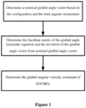
- the multi-objective optimal manipulation control method for the SGCMGs system as shown in the flowchart in Figure 1 as follows.
Landscapes
- Engineering & Computer Science (AREA)
- Remote Sensing (AREA)
- Chemical & Material Sciences (AREA)
- Combustion & Propulsion (AREA)
- Radar, Positioning & Navigation (AREA)
- Aviation & Aerospace Engineering (AREA)
- Automation & Control Theory (AREA)
- Control Of Position, Course, Altitude, Or Attitude Of Moving Bodies (AREA)
Description
- The present application claims priority to
Chinese Patent Application No. 201910872892.7, titled "METHOD FOR DETERMINING GIMBAL ANGULAR VELOCITY OF SGCGM", filed on September 16, 2019 - The present disclosure is related to the field of spacecraft attitude control, and in particular to a manipulation method suitable for a non-redundant cluster of single-gimbal control moment gyroscopes (SGCMGs), which is applicable to high-stability attitude control using a cluster of control moment gyroscopes (CMGs).
- In order to realize the fast attitude maneuver, a cluster of CMGs and a control algorithm are applied for the spacecraft. A widely applied solution is to control an attitude of a satellite using a cluster of control moment gyroscopes (see e.g. the document
CN107544466 ). First, a Jacobian matrix, a singularity measure and a singularity-avoidance vector are calculated based on the measured gimbal angles of CMGs in real time. Then, the singularity-avoidance parameters are calculated based on the singularity measure. At last, the gimbal angular velocity command for each CMG is calculated based on the Jacobian matrix and the desired attitude control torque. In view of spacecraft dual requirements on three-axis attitude control and the singularity avoidance, a redundant configuration with at least four SGCMGs is generally adopted in the control system. In that all gimbal angular vectors corresponding to a particular CMG angular momentum usually form a connected area in the gimbal angular space, it is possible to avoid/escape from the gimbal singularity configuration through gimbal-reconfiguring. Therefore, the conventional research on CMG manipulation methods is mainly focused on the redundant configuration. However, CMG failure may occur in the long-term orbit operation due to some factors, such as the poor lubrication of mechanical bearings caused by the spacecraft long-term in-orbit fast attitude maneuver and radial eccentric load of the CMG high-speed rotor axis, and thereby invalidates the spacecraft. The CMG failures have occurred many times on the International Space Station. - Once only three SGCMGs are working in the SGCMG system due to malfunctions, the system becomes a non-redundant configured system. Different from a redundant system, gimbal angular vectors corresponding to a particular CMG angular momentum in the non-redundant system are finite isolated points in the gimbal angular space, so singularity avoidance/ escape cannot be realized through gimbal-reconfiguring. When the CMG angular momentum returns back to its initial value after the attitude maneuver, the gimbal angles cannot be ensured to return back to its initial state instead of an unexpected state. If the unexpected state is or is close to a singularity state, the attitude of the spacecraft may be out of control in subsequent attitude stabilization control. Therefore, the existing manipulation methods based on a redundant CMG system are not applicable to a non-redundant system.
- The manipulation method suitable for a non-redundant cluster of SGCMGs is provided by the present disclosure to solve the problems in the conventional technology. The method can not only be used in the redundant SGCMGs system, but also in the non-redundant three SGCMGs system which cannot realize the singularity avoidance/escape with a gimbal reconstruction strategy. Meanwhile, the spacecraft can avoid the loss of three-axis attitude maneuver ability resulting from the CMGs gimbal singular configuration when the spacecraft attitude maneuver is done.
- The technical solutions according to the present disclosure are described as follows.
- A manipulation method suitable for a non-redundant cluster of SGCMGs is provided. A spacecraft is equipped with n SGCMGs each having the same angular momentum amplitude. The method includes the following step 1) to 3).
- In
step 1, a nominal gimbal angle vector for the n SGCMGs is determined based on the configuration and the total angular momentum of the n SGCMGs. The total angular momentum H of the n SGCMGs in step 1) is usually selected to be zero and the singularity measure J D of the n-SGCMGs system is expected to be the maximum with the determined nominal gimbal angle vector. - In step 2, the Jacobian matrix J acob of the n-SGCMGs system is determined based on the SGCMGs real-time gimbal angles. In addition, the deviation angle vector Δ δ of the gimbal angle vector of the SGCMGs from the nominal gimbal angle vector δ 0 is determined based on the real-time gimbal angle and the nominal gimbal angle of the configuration of the n SGCMGs determined in step 1).
- In step 3, the gimbal angular velocity command vector δ̇ r of the SGCMGs is determined based on the Jacobian matrix J acob and the deviation angle vector Δ δ , determined in step 2), and the gimbal angular velocity command vector δ̇ r of the SGCMGs is used to drive the SGCMG system.
- The Jacobian matrix J acob of n-SGCMGs system in step 2 is determined as follows:


- Compared with the conventional technology, the present disclosure has the following advantages.
- 1) With the method in the present disclosure, the existing SGCMGs configuration system is fully utilized. A new rule for manipulating the SGCMGs system is obtained based on multi-objective optimization technology, solving the problems that the non-redundant SGCMGs system cannot realize singularity avoidance/escape and the satellite loses ability of three-axis attitude control.
- 2) With the method according to the present disclosure, by constructing a multi-objective optimization cost function considering the deviation of the gimbal angle from the nominal value, the amplitude of the gimbal angle command, and the output torque deviation, a multi-objective CMG manipulation rule is obtained in an optimal manner, reconciling the contradiction between singularity avoidance and three-axis attitude control, and ensuring high-performance attitude maneuver control even in the non-redundant SGCMGs system.
-
-
Figure 1 is a flowchart of the present method according to the present disclosure; -
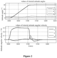
Figure 2 shows curves resenting three-axis attitude angles and angular velocities of a spacecraft; and -
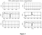
Figure 3 shows curves representing low-velocity gimbal angular velocity commands for SGCMGs. - A cluster of single-gimbal control moment gyroscopes is referred to as a cluster of SGCMGs. Deploying a cluster of SGCMGs is a major trend for spacecraft high-performance attitude maneuver control in the world. Fast attitude maneuver for a long-term in-orbit spacecraft may cause the SGCMGs gimbal angle vector to be close to or trapped in a singularity state after attitude maneuver, resulting in an instable system. In view of spacecraft dual requirements on three-axis attitude control and singularity avoidance, a manipulation method suitable for the non-redundant SGCMGs system is provided according to the present disclosure. A multi-objective optimization cost function is creatively proposed by considering the deviation of a gimbal angle from the nominal value, the amplitude of gimbal angle command, and the output torque deviation. A new rule for manipulating a SGCMG system is obtained based on multi-objective optimization technology. With the method, singularity avoidance in attitude maneuver and recovery to the nominal gimbal angle after the attitude maneuver are realized. The contradiction between singularity avoidance and attitude control is reconciled, and the high-performance attitude maneuver in any direction is ensured, thereby improving ability of the attitude maneuver for the non-redundant SGCMGs system greatly. The effectiveness of the method is verified by mathematical simulation.
- The method according to the present disclosure includes the
following steps 1 to 3. - In
step 1, for each of different clusters of SGCMGs, a nominal gimbal angle vector of the cluster is determined based on factors that the total angular momentum of the cluster is zero, the singularity measure of a configuration of the CMG cluster is large, and the SGCMGs system has the same moment output capacity in all directions as far as possible. - In step 2, the gimbal angle vector δ of the SGCMGs is collected in real time. The Jacobian matrix J acob of gimbal angle kinematic equation of the n-SGCMGs system and the deviation vector Δ δ = δ 0 - δ of the gimbal angle from the nominal gimbal angle are calculated.
- In step 3, a comprehensive multi-objective optimization cost function is constructed considering the deviation of the gimbal angle from the nominal gimbal angle, the amplitude of gimbal angle command, and the output torque deviation. A gimbal angular command vector δ r for the SGCMGs is calculated by minimizing the cost function. In implementation, singularity avoidance parameters α 1 and α 2 are adjusted in real time based on periodic attitude maneuver and the singularity measure. Further, a gimbal angular velocity command vector δ̇ r for the CMGs can be also calculated based on the Jacobian matrix J acob and the desired attitude control torque τ r . Attitude control is then performed base on the afore-mentioned input.
- In a case that a new cluster of CMGs is used, it is required to adjust the attitude angular rate, the angular acceleration and the control parameters for spacecraft attitude maneuvers based on an envelope of angular momentums of the new cluster.
- As shown in
Figure 1 , the manipulation method suitable for a non-redundant cluster of SGCMGs is provided according to the present disclosure. The method includes the following steps 1) to 3). - In step 1), n SGCMGs are numbered from 1 to n. A nominal gimbal angle vector δ 0 = [ δ 01 ... δ 0 i... δ 0n ] T is determined for a configuration of the n-SGCMGs, where δ 0i represents a nominal gimbal angle of ith SGCMG, the variable i is greater than or equal to 1 and less than or equal to n, and n is a positive integer greater than or equal to 3.
- The determined nominal gimbal angle vector of the configuration of the n SGCMGs usually brings the total angular momentum H of the n-SGCMGs system to be zero and the singularity measure J D of the system to be large.
- That is, H = h( A sin δ 0 + B cos δ 0 ) E = [0 0 0] T and J D=det( J acob · J acob T ) is large, where J acob = A cos δ 0 - B sin δ 0, and h represents the angular momentum amplitude of each SGCMG high-speed rotor. The satellite is provided with n SGCMGs each having the same angular momentum. H represents the total angular momentum of the n SGCMGs. A and B represent coefficient matrices related to installation orientations of gimbal axes of the SGCMGs. The ith column of the matrix A corresponds to the angular momentum direction of a high-speed rotor of the ith SGCMG in a case of a gimbal angle of the ith SGCMG being 90°. The ith column of the matrix B corresponds to the angular momentum direction of a high-speed rotor of the ith SGCMG in a case of the gimbal angle of the ith SGCMG being 0°. The variable E represents an n-dimensional vector E = [1 1 ... 1] T. The variable J D represents the singularity measure of the n-SGCMGs system. The symbol det represents solving a determinant. The matrix sin δ 0 and cos δ 0 respectively represent a sine diagonal matrix and a cosine diagonal matrix corresponding to the nominal gimbal angle of the ith SGCMG. The matrix sin δ 0 and cos δ 0 are expressed respectivelly as:

- In step 2), given n SGCMGs with gimbal angles of δ 1 δ 2 ... δ n, respectively, the Jacobian matrix J acob is determined based on the real-time gimbal angles δ i , where i is greater than or equal to 1 and less than or equal to n. In addition, the deviation Δ δ of the gimbal angle from the nominal gimbal angle is determined based on the real-time gimbal angle vector of the SGCMGs and the nominal gimbal angle vector of the configuration of the n SGCMGs determined in step 1).
- The Jacob matrix J acob is determined according to:


- The deviation vector Δ δ of the gimbal angle from the nominal gimbal angle is determined according to:


- In Step 3), by constructing a multi-objective optimization cost function considering a deviation of the gimbal angle from the nominal gimbal angle, the amplitude of the gimbal angle command and the output torque error, a SGCMG manipulation rule synthesizing the above objectives is obtained in an optimal manner. The gimbal angular velocity command δ̇ r of the SGCMGs is determined, according to the multi-objective optimal cost function, based on the torque command τ r obtained from the attitude control law, the Jacob matrix J acob and the deviation of the gimbal angle from the nominal gimbal angle determined in step 2). The gimbal angular velocity command of the SGCMGs is utilized to drive the gimbal mechanism parts of the SGCMGs to generate the satellite attitude control torque.
- In step 3), the gimbal angular velocity command δ̇ r of the SGCMGs is determined according to:


- In Example 1, a spacecraft is equipped with six SGCMGs in pentapyramid configuration. The CMGs are numbered as CMG1, CMG2, CMG3, CMG4, CMG5 and CMG6. The multi-objective optimal manipulation control method for the SGCMGs system, as shown in the flowchart in
Figure 1 as follows. - 1) In the initial operation of the spacecraft, all CMGs operate normally. In this case, a nominal gimbal angle vector δ CMG0= [88.03 -92.32 -92.41 60.740591 -116.144 -145.265]T( deg ) is selected, so that the total angular momentum H for this configuration is nearly zero, and the singularity measure J D is equal to 7.299, and the CMGs have substantially the same moment output capacity in all directions.
- 2) 2000 seconds later, assume the CMG1, the CMG2 and the CMG5 to be malfunctioned. The other three CMGs are operated. In this case, with the selected nominal gimbal angle vector δ CMGO=[0 0 242.2276997 297.7723 0 270]T ( deg ) , the corresponding total angular momentum H for the configuration is nearly zero, and singularity measure J D is equal to 0.72, and the CMGs have substantially the same moment output capacity in all directions.
- 3) 5000 seconds later, a maneuver with a roll angle command of 30° is scheduled. In this case, singularity avoidance parameters α 1 and α 2 are selected as the multi-objective optimization method, based on the real time gimbal angles measured from the CMG3, the CMG4 and the CMG6. In addition, the desired attitude control torque is calculated based on the spacecraft attitude angle error and the angular rate error. Thus, the gimbal angular velocity command for each CMG is calculated to perform attitude maneuver control.
Figure 3 shows curves representing gimbal angular velocity commands for the three CMGs.Figure 2 shows curves representing the tri-axial attitude angle and the angular velocity of the spacecraft. Attitude maneuver and attitude stabilization control are achieved normally.
Claims (5)
- A manipulation method applicable for a non-redundant cluster of Single Gimbal Control Moment Gyroscope SGCMGs, wherein a spacecraft is equipped with n SGCMGs each having a same angular momentum, wherein n is a positive integer greater than or equal to 3; characterised by the fact that
the method comprises:1) determining a nominal gimbal angle vector for a configuration of the n-SGCMGs based on the configuration and a total angular momentum of the n-SGCMGs;2) determining a Jacobian matrix J acob of a gimbal angle kinematic equation based on real-time gimbal angles of the n-SGCMGs, and determining a deviation Δ δ of a gimbal angle vector from the nominal gimbal angle vector based on the gimbal angle vector and the nominal gimbal angle vector of the n SGCMGs determined in step 1); and3) determining a gimbal angular velocity command δ̇ r of the SGCMGs based on the Jacobian matrix J acob and the deviation Δ δ determined in step 2). - The manipulation method according to claim 1, wherein
the nominal gimbal angle vector of the configuration of the n SGCMGs in step 1) brings the total angular momentum H of the n-SGCMGs system to be zero and the singularity measure J D of the system to be maximum. - The manipulation method according to claim 1 or 2, wherein the Jacobian matrix of the gimbal angle kinematic equation in step 2) is determined according to:

 δi represents a gimbal angle of an ith SGCMG, i is greater than or equal to 1 and less than or equal to n, and the n SGCMGs are numbered from 1 to n; andA and B represent 3 × n-dimensional coefficient matrices related to installation orientations of gimbal axes of the n SGCMGs, an ith column of the matrix A corresponds to an angular momentum direction of a high-speed rotor of the ith SGCMG in a case of the gimbal angle of the ith SGCMG being equal to 90°, and the ith column of the matrix B corresponds to the angular momentum direction of the high-speed rotor of the ith SGCMG in a case of the gimbal angle of the ith SGCMG being equal to 0°.
 - The manipulation method according to claim 3, wherein the deviation Δ δ in step 2) is determined according to:


- The manipulation method according to claim 4, wherein the gimbal angular velocity command δ̇ r of the SGCMGs in step 3) is determined according to:


 T s represents a sampling period of the SGCMGs;h represents the angular momentum amplitude of the SGCMGs;I represents an n-dimensional unit matrix;α 1 and α 2 represent designed singularity avoidance parameters, and α 1 and α 2 are greater than or equal to 0;δ r represents the gimbal angular command; andτ r represents a desired attitude control torque.
Applications Claiming Priority (2)
| Application Number | Priority Date | Filing Date | Title |
|---|---|---|---|
| CN201910872892.7A CN110723316B (en) | 2019-09-16 | 2019-09-16 | Method for determining angular velocity of SGCMG framework |
| PCT/CN2020/109919 WO2021052087A1 (en) | 2019-09-16 | 2020-08-19 | Manipulation method suitable for non-redundant sgcmg group |
Publications (3)
| Publication Number | Publication Date |
|---|---|
| EP4032816A1 EP4032816A1 (en) | 2022-07-27 |
| EP4032816A4 EP4032816A4 (en) | 2023-11-22 |
| EP4032816B1 true EP4032816B1 (en) | 2024-11-06 |
Family
ID=69219087
Family Applications (1)
| Application Number | Title | Priority Date | Filing Date |
|---|---|---|---|
| EP20866217.1A Active EP4032816B1 (en) | 2019-09-16 | 2020-08-19 | Manipulation method suitable for non-redundant sgcmg group |
Country Status (3)
| Country | Link |
|---|---|
| EP (1) | EP4032816B1 (en) |
| CN (1) | CN110723316B (en) |
| WO (1) | WO2021052087A1 (en) |
Families Citing this family (5)
| Publication number | Priority date | Publication date | Assignee | Title |
|---|---|---|---|---|
| CN110723316B (en) * | 2019-09-16 | 2020-09-18 | 北京控制工程研究所 | Method for determining angular velocity of SGCMG framework |
| CN111891401B (en) * | 2020-06-28 | 2022-07-05 | 北京控制工程研究所 | CMG group return nominal configuration control method, system and medium based on zero-motion optimization |
| CN115525059B (en) * | 2022-09-05 | 2025-09-26 | 清华大学 | Single-frame control moment gyroscope group determination method, device, equipment, and storage medium |
| CN115563720B (en) * | 2022-12-01 | 2026-03-24 | 中国西安卫星测控中心 | On-orbit singularity analysis method for single-frame control moment gyroscope groups |
| CN119160416B (en) * | 2024-11-20 | 2025-02-25 | 杭州电子科技大学 | A stereoscopic imaging satellite attitude control method based on feedforward model prediction |
Citations (1)
| Publication number | Priority date | Publication date | Assignee | Title |
|---|---|---|---|---|
| CN110597274A (en) * | 2019-09-16 | 2019-12-20 | 北京控制工程研究所 | A Method for Determining Angular Velocity of SGCMG Dynamic Frame Adapted to Attitude Redirection |
Family Cites Families (12)
| Publication number | Priority date | Publication date | Assignee | Title |
|---|---|---|---|---|
| FR2826470B1 (en) * | 2001-06-26 | 2003-09-19 | Astrium Sas | METHOD AND DEVICE FOR STEERING THE ATTITUDE AND GUIDANCE OF A SATELLITE BY A GYRODYNES CLUSTER |
| US8880246B1 (en) * | 2012-08-22 | 2014-11-04 | United States Of America As Represented By The Secretary Of The Navy | Method and apparatus for determining spacecraft maneuvers |
| CN103592848B (en) * | 2013-11-06 | 2017-01-11 | 北京控制工程研究所 | Method for accurately and quickly manipulating variable speed control moment spinning top group |
| CN103869704B (en) * | 2014-04-08 | 2016-05-25 | 哈尔滨工业大学 | Based on the robot for space star arm control method for coordinating of expansion Jacobian matrix |
| CN105388902B (en) * | 2015-11-30 | 2018-04-27 | 北京控制工程研究所 | A kind of unusual bypassing method of control-moment gyro based on instruction Torque vector control |
| CN106218922B (en) * | 2016-07-27 | 2018-06-15 | 中国科学院长春光学精密机械与物理研究所 | The joint actuating mechanism controls method of flexible agility satellite |
| CN107544466B (en) * | 2017-09-15 | 2019-08-09 | 北京控制工程研究所 | A Fault Diagnosis Method for Low Speed Frame of Single Frame Control Moment Gyroscope |
| CN107992062B (en) * | 2017-11-28 | 2020-10-27 | 南京航空航天大学 | Spatial high-dynamic target high-precision attitude tracking control method based on hybrid actuating mechanism |
| CN108333944B (en) * | 2018-02-27 | 2020-05-15 | 北京控制工程研究所 | CMG manipulation method and system based on frame angle adaptive adjustment |
| CN109871025B (en) * | 2019-02-28 | 2020-09-18 | 北京控制工程研究所 | Method for designing control law of variable-speed control moment gyroscope |
| CN110697085B (en) * | 2019-09-16 | 2020-09-18 | 北京控制工程研究所 | A satellite control method combining dual SGCMG and magnetic torquer |
| CN110723316B (en) * | 2019-09-16 | 2020-09-18 | 北京控制工程研究所 | Method for determining angular velocity of SGCMG framework |
-
2019
- 2019-09-16 CN CN201910872892.7A patent/CN110723316B/en active Active
-
2020
- 2020-08-19 WO PCT/CN2020/109919 patent/WO2021052087A1/en not_active Ceased
- 2020-08-19 EP EP20866217.1A patent/EP4032816B1/en active Active
Patent Citations (1)
| Publication number | Priority date | Publication date | Assignee | Title |
|---|---|---|---|---|
| CN110597274A (en) * | 2019-09-16 | 2019-12-20 | 北京控制工程研究所 | A Method for Determining Angular Velocity of SGCMG Dynamic Frame Adapted to Attitude Redirection |
Also Published As
| Publication number | Publication date |
|---|---|
| EP4032816A1 (en) | 2022-07-27 |
| EP4032816A4 (en) | 2023-11-22 |
| WO2021052087A1 (en) | 2021-03-25 |
| CN110723316A (en) | 2020-01-24 |
| CN110723316B (en) | 2020-09-18 |
Similar Documents
| Publication | Publication Date | Title |
|---|---|---|
| EP4032816A1 (en) | Manipulation method suitable for non-redundant sgcmg group | |
| CN106292681B (en) | A satellite active fault-tolerant control method based on observer and online control assignment | |
| CN105867401B (en) | The spacecraft attitude fault tolerant control method of single-gimbal control moment gyros | |
| Vadali et al. | Preferred gimbal angles for single gimbal control moment gyros | |
| Biggs et al. | Optimal geometric motion planning for a spin-stabilized spacecraft | |
| US9643740B2 (en) | Gyroless three-axis sun acquisition using sun sensor and unscented kalman filter | |
| CN103592848B (en) | Method for accurately and quickly manipulating variable speed control moment spinning top group | |
| EP0769736A1 (en) | Method for inclined orbit attitude control for momentum bias spacecraft | |
| EP3854698B1 (en) | Orientation control device, satellite, orientation control method, and program | |
| US6089508A (en) | Autonomous spacecraft safing with reaction wheels | |
| CN103112603B (en) | Method for building normal gestures of under-actuated high-speed spinning satellite | |
| CN104527994A (en) | Different-surface crossover quick-change track fixed time stable posture pointing direction tracking control method | |
| EP4112482B1 (en) | Orbital attitude control device, satellite, orbital attitude control method, and program | |
| US6360996B1 (en) | Steering control for skewed scissors pair CMG clusters | |
| JP2004535324A5 (en) | ||
| CN103034237B (en) | Spacecraft attitude maneuver control method using two single-frame control moment gyroscopes | |
| Kwon et al. | Pointing control of spacecraft using two SGCMGs via LPV control theory | |
| US6138953A (en) | Slew rate direction determination for acquisition maneuvers using reaction wheels | |
| EP2316736B1 (en) | Methods and systems for imposing a momentum boundary while reorienting an agile vehicle with control moment gyroscopes | |
| Wu et al. | Attitude control of spacecraft: mixed h/h approach | |
| Defendini et al. | Low cost CMG-based AOCS designs | |
| CN103336528B (en) | A kind of underactuated spacecraft three-axis attitude stabilization control method | |
| Noumi et al. | Fault-tolerant attitude control systems for satellite equipped with control moment gyros | |
| US7376496B1 (en) | Spacecraft magnetic momentum control system | |
| Anderson et al. | Attitude determination and control system simulation and analysis for low-cost micro-satellites |
Legal Events
| Date | Code | Title | Description |
|---|---|---|---|
| STAA | Information on the status of an ep patent application or granted ep patent |
Free format text: STATUS: THE INTERNATIONAL PUBLICATION HAS BEEN MADE |
|
| PUAI | Public reference made under article 153(3) epc to a published international application that has entered the european phase |
Free format text: ORIGINAL CODE: 0009012 |
|
| STAA | Information on the status of an ep patent application or granted ep patent |
Free format text: STATUS: REQUEST FOR EXAMINATION WAS MADE |
|
| 17P | Request for examination filed |
Effective date: 20220316 |
|
| AK | Designated contracting states |
Kind code of ref document: A1 Designated state(s): AL AT BE BG CH CY CZ DE DK EE ES FI FR GB GR HR HU IE IS IT LI LT LU LV MC MK MT NL NO PL PT RO RS SE SI SK SM TR |
|
| DAV | Request for validation of the european patent (deleted) | ||
| DAX | Request for extension of the european patent (deleted) | ||
| A4 | Supplementary search report drawn up and despatched |
Effective date: 20231023 |
|
| RIC1 | Information provided on ipc code assigned before grant |
Ipc: B64G 1/24 20060101ALI20231017BHEP Ipc: B64G 1/28 20060101AFI20231017BHEP |
|
| GRAP | Despatch of communication of intention to grant a patent |
Free format text: ORIGINAL CODE: EPIDOSNIGR1 |
|
| STAA | Information on the status of an ep patent application or granted ep patent |
Free format text: STATUS: GRANT OF PATENT IS INTENDED |
|
| INTG | Intention to grant announced |
Effective date: 20240705 |
|
| P01 | Opt-out of the competence of the unified patent court (upc) registered |
Free format text: CASE NUMBER: APP_48065/2024 Effective date: 20240821 |
|
| GRAS | Grant fee paid |
Free format text: ORIGINAL CODE: EPIDOSNIGR3 |
|
| GRAA | (expected) grant |
Free format text: ORIGINAL CODE: 0009210 |
|
| STAA | Information on the status of an ep patent application or granted ep patent |
Free format text: STATUS: THE PATENT HAS BEEN GRANTED |
|
| AK | Designated contracting states |
Kind code of ref document: B1 Designated state(s): AL AT BE BG CH CY CZ DE DK EE ES FI FR GB GR HR HU IE IS IT LI LT LU LV MC MK MT NL NO PL PT RO RS SE SI SK SM TR |
|
| REG | Reference to a national code |
Ref country code: GB Ref legal event code: FG4D |
|
| REG | Reference to a national code |
Ref country code: CH Ref legal event code: EP |
|
| REG | Reference to a national code |
Ref country code: DE Ref legal event code: R096 Ref document number: 602020041030 Country of ref document: DE |
|
| REG | Reference to a national code |
Ref country code: IE Ref legal event code: FG4D |
|
| REG | Reference to a national code |
Ref country code: LT Ref legal event code: MG9D |
|
| REG | Reference to a national code |
Ref country code: NL Ref legal event code: MP Effective date: 20241106 |
|
| PG25 | Lapsed in a contracting state [announced via postgrant information from national office to epo] |
Ref country code: PT Free format text: LAPSE BECAUSE OF FAILURE TO SUBMIT A TRANSLATION OF THE DESCRIPTION OR TO PAY THE FEE WITHIN THE PRESCRIBED TIME-LIMIT Effective date: 20250306 Ref country code: IS Free format text: LAPSE BECAUSE OF FAILURE TO SUBMIT A TRANSLATION OF THE DESCRIPTION OR TO PAY THE FEE WITHIN THE PRESCRIBED TIME-LIMIT Effective date: 20250306 Ref country code: HR Free format text: LAPSE BECAUSE OF FAILURE TO SUBMIT A TRANSLATION OF THE DESCRIPTION OR TO PAY THE FEE WITHIN THE PRESCRIBED TIME-LIMIT Effective date: 20241106 |
|
| PG25 | Lapsed in a contracting state [announced via postgrant information from national office to epo] |
Ref country code: FI Free format text: LAPSE BECAUSE OF FAILURE TO SUBMIT A TRANSLATION OF THE DESCRIPTION OR TO PAY THE FEE WITHIN THE PRESCRIBED TIME-LIMIT Effective date: 20241106 Ref country code: NL Free format text: LAPSE BECAUSE OF FAILURE TO SUBMIT A TRANSLATION OF THE DESCRIPTION OR TO PAY THE FEE WITHIN THE PRESCRIBED TIME-LIMIT Effective date: 20241106 |
|
| REG | Reference to a national code |
Ref country code: AT Ref legal event code: MK05 Ref document number: 1739148 Country of ref document: AT Kind code of ref document: T Effective date: 20241106 |
|
| PG25 | Lapsed in a contracting state [announced via postgrant information from national office to epo] |
Ref country code: BG Free format text: LAPSE BECAUSE OF FAILURE TO SUBMIT A TRANSLATION OF THE DESCRIPTION OR TO PAY THE FEE WITHIN THE PRESCRIBED TIME-LIMIT Effective date: 20241106 |
|
| PG25 | Lapsed in a contracting state [announced via postgrant information from national office to epo] |
Ref country code: ES Free format text: LAPSE BECAUSE OF FAILURE TO SUBMIT A TRANSLATION OF THE DESCRIPTION OR TO PAY THE FEE WITHIN THE PRESCRIBED TIME-LIMIT Effective date: 20241106 |
|
| PG25 | Lapsed in a contracting state [announced via postgrant information from national office to epo] |
Ref country code: NO Free format text: LAPSE BECAUSE OF FAILURE TO SUBMIT A TRANSLATION OF THE DESCRIPTION OR TO PAY THE FEE WITHIN THE PRESCRIBED TIME-LIMIT Effective date: 20250206 |
|
| PG25 | Lapsed in a contracting state [announced via postgrant information from national office to epo] |
Ref country code: GR Free format text: LAPSE BECAUSE OF FAILURE TO SUBMIT A TRANSLATION OF THE DESCRIPTION OR TO PAY THE FEE WITHIN THE PRESCRIBED TIME-LIMIT Effective date: 20250207 Ref country code: LV Free format text: LAPSE BECAUSE OF FAILURE TO SUBMIT A TRANSLATION OF THE DESCRIPTION OR TO PAY THE FEE WITHIN THE PRESCRIBED TIME-LIMIT Effective date: 20241106 Ref country code: AT Free format text: LAPSE BECAUSE OF FAILURE TO SUBMIT A TRANSLATION OF THE DESCRIPTION OR TO PAY THE FEE WITHIN THE PRESCRIBED TIME-LIMIT Effective date: 20241106 |
|
| PG25 | Lapsed in a contracting state [announced via postgrant information from national office to epo] |
Ref country code: PL Free format text: LAPSE BECAUSE OF FAILURE TO SUBMIT A TRANSLATION OF THE DESCRIPTION OR TO PAY THE FEE WITHIN THE PRESCRIBED TIME-LIMIT Effective date: 20241106 |
|
| PG25 | Lapsed in a contracting state [announced via postgrant information from national office to epo] |
Ref country code: RS Free format text: LAPSE BECAUSE OF FAILURE TO SUBMIT A TRANSLATION OF THE DESCRIPTION OR TO PAY THE FEE WITHIN THE PRESCRIBED TIME-LIMIT Effective date: 20250206 |
|
| PG25 | Lapsed in a contracting state [announced via postgrant information from national office to epo] |
Ref country code: SM Free format text: LAPSE BECAUSE OF FAILURE TO SUBMIT A TRANSLATION OF THE DESCRIPTION OR TO PAY THE FEE WITHIN THE PRESCRIBED TIME-LIMIT Effective date: 20241106 |
|
| PG25 | Lapsed in a contracting state [announced via postgrant information from national office to epo] |
Ref country code: DK Free format text: LAPSE BECAUSE OF FAILURE TO SUBMIT A TRANSLATION OF THE DESCRIPTION OR TO PAY THE FEE WITHIN THE PRESCRIBED TIME-LIMIT Effective date: 20241106 |
|
| PG25 | Lapsed in a contracting state [announced via postgrant information from national office to epo] |
Ref country code: EE Free format text: LAPSE BECAUSE OF FAILURE TO SUBMIT A TRANSLATION OF THE DESCRIPTION OR TO PAY THE FEE WITHIN THE PRESCRIBED TIME-LIMIT Effective date: 20241106 |
|
| PG25 | Lapsed in a contracting state [announced via postgrant information from national office to epo] |
Ref country code: RO Free format text: LAPSE BECAUSE OF FAILURE TO SUBMIT A TRANSLATION OF THE DESCRIPTION OR TO PAY THE FEE WITHIN THE PRESCRIBED TIME-LIMIT Effective date: 20241106 |
|
| PG25 | Lapsed in a contracting state [announced via postgrant information from national office to epo] |
Ref country code: SK Free format text: LAPSE BECAUSE OF FAILURE TO SUBMIT A TRANSLATION OF THE DESCRIPTION OR TO PAY THE FEE WITHIN THE PRESCRIBED TIME-LIMIT Effective date: 20241106 |
|
| PG25 | Lapsed in a contracting state [announced via postgrant information from national office to epo] |
Ref country code: CZ Free format text: LAPSE BECAUSE OF FAILURE TO SUBMIT A TRANSLATION OF THE DESCRIPTION OR TO PAY THE FEE WITHIN THE PRESCRIBED TIME-LIMIT Effective date: 20241106 |
|
| PG25 | Lapsed in a contracting state [announced via postgrant information from national office to epo] |
Ref country code: IT Free format text: LAPSE BECAUSE OF FAILURE TO SUBMIT A TRANSLATION OF THE DESCRIPTION OR TO PAY THE FEE WITHIN THE PRESCRIBED TIME-LIMIT Effective date: 20241106 |
|
| REG | Reference to a national code |
Ref country code: DE Ref legal event code: R097 Ref document number: 602020041030 Country of ref document: DE |
|
| PG25 | Lapsed in a contracting state [announced via postgrant information from national office to epo] |
Ref country code: SE Free format text: LAPSE BECAUSE OF FAILURE TO SUBMIT A TRANSLATION OF THE DESCRIPTION OR TO PAY THE FEE WITHIN THE PRESCRIBED TIME-LIMIT Effective date: 20241106 |
|
| PLBE | No opposition filed within time limit |
Free format text: ORIGINAL CODE: 0009261 |
|
| STAA | Information on the status of an ep patent application or granted ep patent |
Free format text: STATUS: NO OPPOSITION FILED WITHIN TIME LIMIT |
|
| PGFP | Annual fee paid to national office [announced via postgrant information from national office to epo] |
Ref country code: DE Payment date: 20250716 Year of fee payment: 6 |
|
| 26N | No opposition filed |
Effective date: 20250807 |
|
| PGFP | Annual fee paid to national office [announced via postgrant information from national office to epo] |
Ref country code: FR Payment date: 20250721 Year of fee payment: 6 |
|
| REG | Reference to a national code |
Ref country code: CH Ref legal event code: H13 Free format text: ST27 STATUS EVENT CODE: U-0-0-H10-H13 (AS PROVIDED BY THE NATIONAL OFFICE) Effective date: 20260324 |
|
| PG25 | Lapsed in a contracting state [announced via postgrant information from national office to epo] |
Ref country code: MC Free format text: LAPSE BECAUSE OF FAILURE TO SUBMIT A TRANSLATION OF THE DESCRIPTION OR TO PAY THE FEE WITHIN THE PRESCRIBED TIME-LIMIT Effective date: 20241106 |
|
| PG25 | Lapsed in a contracting state [announced via postgrant information from national office to epo] |
Ref country code: LU Free format text: LAPSE BECAUSE OF NON-PAYMENT OF DUE FEES Effective date: 20250819 |
|
| PG25 | Lapsed in a contracting state [announced via postgrant information from national office to epo] |
Ref country code: CH Free format text: LAPSE BECAUSE OF NON-PAYMENT OF DUE FEES Effective date: 20250831 |
|
| GBPC | Gb: european patent ceased through non-payment of renewal fee |
Effective date: 20250819 |