EP4032800A1 - Connector for a structurally integrated line system - Google Patents
Connector for a structurally integrated line system Download PDFInfo
- Publication number
- EP4032800A1 EP4032800A1 EP22150674.4A EP22150674A EP4032800A1 EP 4032800 A1 EP4032800 A1 EP 4032800A1 EP 22150674 A EP22150674 A EP 22150674A EP 4032800 A1 EP4032800 A1 EP 4032800A1
- Authority
- EP
- European Patent Office
- Prior art keywords
- connector
- structurally integrated
- end portion
- line
- cutout
- Prior art date
- Legal status (The legal status is an assumption and is not a legal conclusion. Google has not performed a legal analysis and makes no representation as to the accuracy of the status listed.)
- Withdrawn
Links
Images


Classifications
-
- F—MECHANICAL ENGINEERING; LIGHTING; HEATING; WEAPONS; BLASTING
- F16—ENGINEERING ELEMENTS AND UNITS; GENERAL MEASURES FOR PRODUCING AND MAINTAINING EFFECTIVE FUNCTIONING OF MACHINES OR INSTALLATIONS; THERMAL INSULATION IN GENERAL
- F16L—PIPES; JOINTS OR FITTINGS FOR PIPES; SUPPORTS FOR PIPES, CABLES OR PROTECTIVE TUBING; MEANS FOR THERMAL INSULATION IN GENERAL
- F16L41/00—Branching pipes; Joining pipes to walls
- F16L41/08—Joining pipes to walls or pipes, the joined pipe axis being perpendicular to the plane of a wall or to the axis of another pipe
- F16L41/082—Non-disconnectable joints, e.g. soldered, adhesive or caulked joints
-
- B—PERFORMING OPERATIONS; TRANSPORTING
- B64—AIRCRAFT; AVIATION; COSMONAUTICS
- B64C—AEROPLANES; HELICOPTERS
- B64C1/00—Fuselages; Constructional features common to fuselages, wings, stabilising surfaces or the like
- B64C1/06—Frames; Stringers; Longerons ; Fuselage sections
-
- B—PERFORMING OPERATIONS; TRANSPORTING
- B64—AIRCRAFT; AVIATION; COSMONAUTICS
- B64C—AEROPLANES; HELICOPTERS
- B64C1/00—Fuselages; Constructional features common to fuselages, wings, stabilising surfaces or the like
- B64C1/06—Frames; Stringers; Longerons ; Fuselage sections
- B64C1/064—Stringers; Longerons
-
- B—PERFORMING OPERATIONS; TRANSPORTING
- B64—AIRCRAFT; AVIATION; COSMONAUTICS
- B64D—EQUIPMENT FOR FITTING IN OR TO AIRCRAFT; FLIGHT SUITS; PARACHUTES; ARRANGEMENT OR MOUNTING OF POWER PLANTS OR PROPULSION TRANSMISSIONS IN AIRCRAFT
- B64D13/00—Arrangements or adaptations of air-treatment apparatus for aircraft crew or passengers, or freight space
-
- F—MECHANICAL ENGINEERING; LIGHTING; HEATING; WEAPONS; BLASTING
- F16—ENGINEERING ELEMENTS AND UNITS; GENERAL MEASURES FOR PRODUCING AND MAINTAINING EFFECTIVE FUNCTIONING OF MACHINES OR INSTALLATIONS; THERMAL INSULATION IN GENERAL
- F16L—PIPES; JOINTS OR FITTINGS FOR PIPES; SUPPORTS FOR PIPES, CABLES OR PROTECTIVE TUBING; MEANS FOR THERMAL INSULATION IN GENERAL
- F16L27/00—Adjustable joints; Joints allowing movement
- F16L27/12—Adjustable joints; Joints allowing movement allowing substantial longitudinal adjustment or movement
Definitions
- the invention relates to a connector for a structurally integrated line system of a vehicle, to a structurally integrated line system of a vehicle, and to a vehicle having at least one structurally integrated line system.
- vehicle structures for example fuselage or wing structures of aircraft
- a certain degree of multifunctionality in order to reduce weight.
- An example thereof is the integration of a fluid line in the form of a cavity extending in the structure. This could be situated in a reinforcing component, for example a stringer, and extend from one end of a fuselage component to another end.
- a connector for a structurally integrated line system of a vehicle having a first end portion, a second end portion and a connecting piece extending between the first end portion and the second end portion, wherein the first end portion has at least one contact face for arrangement on a structurally integrated line, wherein at least one of the at least one contact face has a cutout which is surrounded by a closed border, wherein the second end portion has a flange connection for connection to a pipe.
- the connector permits the connection of a single, isolated, structurally integrated line in order to connect it to another line, which can likewise be a structurally integrated line.
- Multiple structurally integrated lines can together form a line system by using in each case a connector according to the invention. To this end, they are each coupled with a connector according to the invention, wherein the two connectors are connected together via a suitable pipe or the like. To this end, the connector has a shape adapted to the structurally integrated line.
- the first end portion has one or more contact faces for connection to the structurally integrated line. At least one of the contact faces has a cutout which is surrounded by a border. The border could delimit the contact face and extends around the periphery of the cutout.
- the contact face in question is adapted to an outer boundary surface of the structurally integrated line in question. It is thereby preferred that the contact face facing the outer boundary surface is configured so as to be complementary to the outer boundary surface, such that it can be applied substantially flush thereto.
- the contact face in question is adhesively bonded, screwed, welded or otherwise connected to the outer boundary surface.
- the outer boundary surface has an opening, which is covered by the cutout. It can thereby be preferred that the opening in the outer boundary surface is smaller than the cutout that covers it, so that the border surrounding the cutout is able to lie flush against the outer boundary surface without any gaps and can be used for sealing.
- the second end portion can be configured for connection to a pipe or other fluid-conducting component. It can be expedient to provide here a flange which is compatible with flanges of generic fluid lines, for example for air.
- the connecting piece By means of the connecting piece, the flange connection is spaced apart from the first end portion and can consequently achieve a certain mechanical compensation between the position of the first end portion and of the second end portion.
- the connecting piece is at least partially resilient or variable in terms of its position or length, in order purposively to provide position and length compensation.
- the connector according to the invention makes it possible to produce a system of structurally integrated lines which are connected to one another in which no adjustments to the structurally integrated lines are required and a stress-free construction is nevertheless achieved. Deformations are compensated for in such a manner that no stresses occur in the components.
- the structurally integrated lines undertake the multifunctional task of fluid transport and of load transfer.
- the first end portion has a first contact face in which the cutout is arranged, wherein the first end portion has a second contact face which protrudes at an angle to the first contact face.
- the structurally integrated line can have an above-mentioned opening, which extends through a lateral surface of its cross-section through which flow takes place and is covered by the first contact face.
- the two contact faces are complementary to the lateral surface and can both be applied flush to the lateral surface.
- a fluidic connection between the structurally integrated line and the connector is produced. Owing to the arrangement of the two contact faces at an angle to one another, the first end portion can be placed on an edge of the lateral surface of the structurally integrated line. It is thereby to be assumed that the lateral surface likewise has at least two surface portions which are at an angle to one another and enclose an edge.
- the second contact face could be free of a cutout.
- the second contact face is consequently configured merely to be brought into surface contact with the lateral surface.
- the cutout is rectangular. Maximum coverage of an opening arranged in the lateral surface of the flow-integrated line can thereby be achieved.
- the cutout could further be surrounded by a border which is likewise rectangular at its outer periphery. Particularly preferably, the border has a uniform local width. Moreover, it does not have any gaps, in order to achieve seal face pairing.
- the cutout could have the same cross-sectional area as that of the structurally integrated line.
- the first end portion has multiple contact faces which form a trapezoidal shape relative to one another.
- the trapezoidal shape of the structurally integrated line has been found to be advantageous for certain applications and production methods, as described, for example, in EP 3 587 249 A . Consequently, it is expedient that the connector is likewise trapezoidal, in order to adapt to the trapezoidal shape and have planar bearing faces. It is conceivable that a longer base of the trapezoidal cross-section of the line is arranged flush on a structural component, while the legs and the shorter base protrude from the structural component.
- the trapezoidal contour of the contact faces is so configured that the contact faces can be placed from outside on a structurally integrated line having such a shape.
- a structurally integrated line with a trapezoidal cross-section is significantly simpler to produce than with a circular cross-section and has already proved itself as a reinforcing profile.
- the connecting piece adjoins the cutout at an angle to a plane spanned by the cutout.
- the connecting piece could, for example, extend perpendicularly to the plane in question and consequently perpendicularly to the direction of flow in the structurally integrated line. It is, however, also conceivable to adapt the extension of the connecting piece, in particular at an inlet, but also at an outlet, to the direction of flow. Consequently, a departure angle of the connector can here be varied in order to be able to adapt the construction to the application.
- the extension of the connecting piece could enclose an angle of, for example, from 30° to 60° with the direction of flow. As a result, lower flow losses overall, adapted to specific applications, can be achieved.
- the connecting piece is particularly preferably configured to establish between the first end portion and the second end portion a stepless transition from a flow cross-section adapted to the structurally integrated line to an at least largely circular cross-section.
- the flow resistance caused by the connector can thus be reduced and preferably minimized.
- the flange connection has a circular flange.
- a circular connecting piece which has a cross-sectional area that is the same size as or larger than the cutout can be arranged at the flange connection. Conventional elements based on circular pipes can be connected thereto.
- the connector particularly preferably has an assembly which is connected to the second end portion and has a sleeve and a pipe, which are inserted into one another so as to be longitudinally displaceable.
- a second connector which is connected by the flange connection to this assembly can be attached thereto.
- a combination of two connectors and such an assembly located between them is accordingly provided. It is thereby also possible that the two connectors are each coupled with a sleeve and a pipe is arranged between the two sleeves.
- the two connectors can each produce a fluidic connection with a structurally integrated line, while the mentioned assembly is used to connect the two structurally integrated lines together.
- the longitudinally displaceable assembly any component stresses and deformations which would additionally load the structure can be equalized and compensated for.
- the construction has a possibility for angle compensation, so that production and installation deviations can be accommodated.
- the connecting piece is particularly preferably at least flexible.
- a pressure-tight and nevertheless flexible fluidic connection can thus be established.
- Numerous variants of a semi-flexible connection are conceivable, which could be based, for example, on a type of corrugated tube with braiding or a sheath.
- the invention relates further to a structurally integrated line system having at least one structural component with at least one line integrated therein and at least one connector according to one of the preceding embodiments, wherein the at least one line has an opening on which the connector is arranged, so that the cutout covers the opening.
- the line system can have at least two structurally integrated lines which are each connected to a connector, wherein an assembly having a sleeve and a pipe, which are inserted into one another so as to be longitudinally displaceable, extends between two connectors.
- an assembly having a sleeve and a pipe which are inserted into one another so as to be longitudinally displaceable, extends between two connectors.
- both connectors it is also possible for both connectors to be coupled with a sleeve, wherein a pipe which is displaceably inserted into the sleeves extends between the sleeves of two connectors.
- the invention relates further to a vehicle having multiple structural components, wherein at least one structural component has at least one structurally integrated line which is connected to a connector according to the above description.
- the at least one structurally integrated line can have multiple structurally integrated lines which form an above-mentioned line system.
- the vehicle could further have at least one system component which interacts with a fluid flowing in the structurally integrated line, wherein the at least one system component is connected directly to the flange connection.
- the vehicle can be an aircraft, wherein at least one structurally integrated line is connected to an air source, for example a bleed air source or an external air source.
- an air source for example a bleed air source or an external air source.
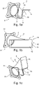
- Figures 1a, 1b and 1c show different views of a connector 2 for a structurally integrated line system. In the following explanation, reference will be made to all three illustrations.
- the connector 2 has a first end portion 4 and a second end portion 6.
- the connecting piece 8 can have a circular cross-section and can be connected to end portions 4 and 6 of any shape.
- the first end portion 4 has a first contact face 10, in which a rectangular cutout 12 is arranged. The cutout is surrounded by a peripheral border 14 which does not have any gaps.
- a second contact face 16 adjoins the first contact face 10 and is at an angle thereto. It should be noted here that the two contact faces 10 and 16 are each at least largely planar and enclose a bend 18. As can be seen in Fig.
- the two contact faces 10 and 16 enclose with one another an angle ⁇ which is slightly more than 90°.
- the two contact faces 10 and 16 thus define between them part of a trapezoidal shape, which is intended to adapt to a trapezoidal, structurally integrated line.
- the second end portion 6 has a flange connection 20, which in the example shown is a circular flange. This is configured to be connected to a pipe, which likewise has a circular cross-section and a corresponding flange.
- the cutout 12 can cover an opening in a lateral surface of a structurally integrated line and thus produce a fluidic connection between the interior of the structurally integrated line and the cross-section of the flange connection 20 through which flow takes place. No modifications to the structurally integrated line are necessary for this purpose, and multiple such structurally integrated lines can be connected together to form a line system. This is shown in the subsequent figures.
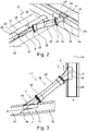
- Fig. 2 shows a line system 21.
- a connector 2 or 2a is arranged on each of the two lines 26 and 28.
- the contact faces 10 and 16 in question are adapted to the lateral surface 30 of the lines 26 and 28, which in the case shown forms a trapezoidal cross-section.
- the two second contact faces 16 lie flush on an upper side 32 of the lines 26 and 28, while the first contact faces 10 are each connected to a leg surface 34.
- a pipe assembly 36 which has a sleeve 38 and a pipe 40 which are mounted relative to one another so as to be displaceable in one another, is formed between the two connectors 2 and 2a.
- the required tightness of the assembly 36 can be produced by means of sealing rings between the sleeve 38 and the pipe 40. These can compensate for distance tolerances due to thermal expansion and mechanical loads on the structural components 22 and 24, and for angular deviations.
- the connecting piece 8a is thereby designed by way of example with a circular cross-section throughout.
- the direction of extension of the pipe assembly 36 can be adapted to the directions of flow in the lines 26 and 28, so that the flow experiences as smooth a change of direction as possible in the region of the connector 2 and lower pressure losses are thus to be expected.
- a direction of flow 42 of the line 26 or 28 in question and a surface normal 44 of the flange connections 20 enclose an angle of about 45°.
- two identical connectors 2 are here connected to the flow-integrated lines 26 and 28.
- the pipe assembly 36 is here arranged in a floating manner and comprises, as mentioned hereinbefore, a sleeve 38 and a pipe 40, which are displaceably mounted in one another.
- Fig. 4 shows a line system 46.
- Three structurally integrated lines 48, 50 and 52 are shown here, each of which is equipped with multiple connectors 2.
- system components 54 are arranged thereon.
- the system components 54 can include non-return valves, pressure reducing valves, pressure or temperature sensors, float valves or the like.
- Fig. 5 shows a line system 56 in which two structurally integrated lines 58 and 60 are connected to connectors 2a. Both connectors 2a have a connecting piece 8 with a circular cross-section. Between the two connectors 2a there is arranged a pipe 40, which on both sides is displaceably arranged in a sleeve 38.
- the connecting piece 8 of the connector 2a on the left in the plane of the drawing is arranged at an angle ⁇ of 30° to the direction of flow 42 in the structurally integrated line 58.
- the connector 2a could have an oval cutout 12 there in this example.
- the connector 2a on the right in the plane of the drawing has a connecting piece 8 which, however, extends perpendicularly to the direction of extension of the structurally integrated line 60, or to the direction of flow given thereby.
- the cutout 12 of the connector 2a could there have a circular cutout 12.
- the two connectors 2a are coupled with the upper side 32 of the structurally integrated lines 58 and 60.
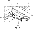
- Fig. 6 shows a line system 62 having two structurally integrated lines 64 and 66.
- Connectors 2 and 2a which are each connected to a sleeve 38 and between which a pipe 40 is displaceably arranged, are arranged here.
- the connector 2 is fluidically connected to the structurally integrated line 64 at a leg surface 34 and has a connecting piece 8 which transitions from a largely rectangular cross-section into a circular cross-section.
- the connector 2a is fluidically connected to an upper side 32 of the structurally integrated line 66 and has a connecting piece 8 which has a circular cross-section throughout.
- the two connectors are arranged perpendicularly to the respective direction of flow.
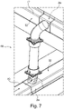
- Fig. 7 shows a line system 68 having two structurally integrated lines 70 and 72 and two connectors 2a connected thereto.
- the two connectors are connected to a sleeve 38, between which sleeves a pipe 40 is mounted in a floating manner.
- the two connectors 2a are seated perpendicularly on an upper side 32 of the respective structurally integrated line 70 or 72 and have a connecting piece 8 with a circular cross-section.
- FIG. 8 shows an aircraft 74 which has at least one line system 21, 41, 46, 56, 62 or 68.
- a structurally integrated line contained therein could be connected to an engine 76 and receive bleed air therefrom.
Landscapes
- Engineering & Computer Science (AREA)
- Mechanical Engineering (AREA)
- Aviation & Aerospace Engineering (AREA)
- General Engineering & Computer Science (AREA)
- Health & Medical Sciences (AREA)
- General Health & Medical Sciences (AREA)
- Pulmonology (AREA)
- Quick-Acting Or Multi-Walled Pipe Joints (AREA)
- Manufacturing & Machinery (AREA)
- Transportation (AREA)
Abstract
Description
- The invention relates to a connector for a structurally integrated line system of a vehicle, to a structurally integrated line system of a vehicle, and to a vehicle having at least one structurally integrated line system.
- It is known to equip vehicle structures, for example fuselage or wing structures of aircraft, with a certain degree of multifunctionality in order to reduce weight. An example thereof is the integration of a fluid line in the form of a cavity extending in the structure. This could be situated in a reinforcing component, for example a stringer, and extend from one end of a fuselage component to another end.
- It would be desirable to increase such multifunctionality without thereby affecting the underlying configuration of the vehicle component and reinforcing components or the like attached thereto. The establishment, for example, of a network of lines with multiple structurally integrated fluid lines connected to one another can make a contribution in this respect.
- Accordingly, it is an object of the invention to propose a structurally integrated line system in which longer line lengths, branches, junctions and other network features are possible, wherein at the same time the underlying configuration of structural components therefor does not have to be changed and moreover structural loads, structural deformations, system loads, production deviations and thermal expansion between individual structural components are nevertheless possible.
- The object is achieved by a connector for a structurally integrated line system having the features of independent claim one. Advantageous embodiments and further developments are to be found in the dependent claims and the following description.
- A connector for a structurally integrated line system of a vehicle is proposed, having a first end portion, a second end portion and a connecting piece extending between the first end portion and the second end portion, wherein the first end portion has at least one contact face for arrangement on a structurally integrated line, wherein at least one of the at least one contact face has a cutout which is surrounded by a closed border, wherein the second end portion has a flange connection for connection to a pipe.
- The connector permits the connection of a single, isolated, structurally integrated line in order to connect it to another line, which can likewise be a structurally integrated line. Multiple structurally integrated lines can together form a line system by using in each case a connector according to the invention. To this end, they are each coupled with a connector according to the invention, wherein the two connectors are connected together via a suitable pipe or the like. To this end, the connector has a shape adapted to the structurally integrated line.
- The first end portion has one or more contact faces for connection to the structurally integrated line. At least one of the contact faces has a cutout which is surrounded by a border. The border could delimit the contact face and extends around the periphery of the cutout. The contact face in question is adapted to an outer boundary surface of the structurally integrated line in question. It is thereby preferred that the contact face facing the outer boundary surface is configured so as to be complementary to the outer boundary surface, such that it can be applied substantially flush thereto. For connection to the outer boundary surface, the contact face in question is adhesively bonded, screwed, welded or otherwise connected to the outer boundary surface. In order to produce a fluidic connection with an interior of the structurally integrated line, the outer boundary surface has an opening, which is covered by the cutout. It can thereby be preferred that the opening in the outer boundary surface is smaller than the cutout that covers it, so that the border surrounding the cutout is able to lie flush against the outer boundary surface without any gaps and can be used for sealing.
- The second end portion can be configured for connection to a pipe or other fluid-conducting component. It can be expedient to provide here a flange which is compatible with flanges of generic fluid lines, for example for air. By means of the connecting piece, the flange connection is spaced apart from the first end portion and can consequently achieve a certain mechanical compensation between the position of the first end portion and of the second end portion. Particularly preferably, the connecting piece is at least partially resilient or variable in terms of its position or length, in order purposively to provide position and length compensation. By means of such a resilient configuration with variable length or variable position, the exchange of components, for example sealing rings, in the installed state could be made possible.
- Overall, the connector according to the invention makes it possible to produce a system of structurally integrated lines which are connected to one another in which no adjustments to the structurally integrated lines are required and a stress-free construction is nevertheless achieved. Deformations are compensated for in such a manner that no stresses occur in the components. The structurally integrated lines undertake the multifunctional task of fluid transport and of load transfer.
- In an advantageous embodiment, the first end portion has a first contact face in which the cutout is arranged, wherein the first end portion has a second contact face which protrudes at an angle to the first contact face. The structurally integrated line can have an above-mentioned opening, which extends through a lateral surface of its cross-section through which flow takes place and is covered by the first contact face. The two contact faces are complementary to the lateral surface and can both be applied flush to the lateral surface. By means of the opening and the cutout, a fluidic connection between the structurally integrated line and the connector is produced. Owing to the arrangement of the two contact faces at an angle to one another, the first end portion can be placed on an edge of the lateral surface of the structurally integrated line. It is thereby to be assumed that the lateral surface likewise has at least two surface portions which are at an angle to one another and enclose an edge.
- Furthermore, the second contact face could be free of a cutout. The second contact face is consequently configured merely to be brought into surface contact with the lateral surface. By means of the contact of two contact faces with the structurally integrated line, load transfer in two planes, which are defined by the contact faces, is made possible. A second contact face is expedient in order to connect the connector to the structurally integrated line with sufficient tightness and strength. The connector per se is not to transfer any loads or scarcely any loads but, owing to the structurally integrated lines, will follow deformations.
- In an advantageous embodiment, the cutout is rectangular. Maximum coverage of an opening arranged in the lateral surface of the flow-integrated line can thereby be achieved. The cutout could further be surrounded by a border which is likewise rectangular at its outer periphery. Particularly preferably, the border has a uniform local width. Moreover, it does not have any gaps, in order to achieve seal face pairing. The cutout could have the same cross-sectional area as that of the structurally integrated line.
- It is particularly advantageous if the first end portion has multiple contact faces which form a trapezoidal shape relative to one another. The trapezoidal shape of the structurally integrated line has been found to be advantageous for certain applications and production methods, as described, for example, in
EP 3 587 249 A . Consequently, it is expedient that the connector is likewise trapezoidal, in order to adapt to the trapezoidal shape and have planar bearing faces. It is conceivable that a longer base of the trapezoidal cross-section of the line is arranged flush on a structural component, while the legs and the shorter base protrude from the structural component. The trapezoidal contour of the contact faces is so configured that the contact faces can be placed from outside on a structurally integrated line having such a shape. A structurally integrated line with a trapezoidal cross-section is significantly simpler to produce than with a circular cross-section and has already proved itself as a reinforcing profile. - In an advantageous embodiment, the connecting piece adjoins the cutout at an angle to a plane spanned by the cutout. The connecting piece could, for example, extend perpendicularly to the plane in question and consequently perpendicularly to the direction of flow in the structurally integrated line. It is, however, also conceivable to adapt the extension of the connecting piece, in particular at an inlet, but also at an outlet, to the direction of flow. Consequently, a departure angle of the connector can here be varied in order to be able to adapt the construction to the application. The extension of the connecting piece could enclose an angle of, for example, from 30° to 60° with the direction of flow. As a result, lower flow losses overall, adapted to specific applications, can be achieved.
- The connecting piece is particularly preferably configured to establish between the first end portion and the second end portion a stepless transition from a flow cross-section adapted to the structurally integrated line to an at least largely circular cross-section. The flow resistance caused by the connector can thus be reduced and preferably minimized.
- In a further advantageous embodiment, the flange connection has a circular flange. A transition between a cross-section that is adapted to the cutout and is thus preferably rectangular and a circular cross-section ending in the circular flange accordingly takes place between the first end portion and the second end portion. A circular connecting piece which has a cross-sectional area that is the same size as or larger than the cutout can be arranged at the flange connection. Conventional elements based on circular pipes can be connected thereto.
- The connector particularly preferably has an assembly which is connected to the second end portion and has a sleeve and a pipe, which are inserted into one another so as to be longitudinally displaceable. A second connector which is connected by the flange connection to this assembly can be attached thereto. For connecting two structurally integrated lines, a combination of two connectors and such an assembly located between them is accordingly provided. It is thereby also possible that the two connectors are each coupled with a sleeve and a pipe is arranged between the two sleeves. The two connectors can each produce a fluidic connection with a structurally integrated line, while the mentioned assembly is used to connect the two structurally integrated lines together. By means of the longitudinally displaceable assembly, any component stresses and deformations which would additionally load the structure can be equalized and compensated for. In addition, the construction has a possibility for angle compensation, so that production and installation deviations can be accommodated.
- The connecting piece is particularly preferably at least flexible. A pressure-tight and nevertheless flexible fluidic connection can thus be established. Numerous variants of a semi-flexible connection are conceivable, which could be based, for example, on a type of corrugated tube with braiding or a sheath.
- The invention relates further to a structurally integrated line system having at least one structural component with at least one line integrated therein and at least one connector according to one of the preceding embodiments, wherein the at least one line has an opening on which the connector is arranged, so that the cutout covers the opening.
- The line system can have at least two structurally integrated lines which are each connected to a connector, wherein an assembly having a sleeve and a pipe, which are inserted into one another so as to be longitudinally displaceable, extends between two connectors. As described hereinbefore, it is also possible for both connectors to be coupled with a sleeve, wherein a pipe which is displaceably inserted into the sleeves extends between the sleeves of two connectors.
- The invention relates further to a vehicle having multiple structural components, wherein at least one structural component has at least one structurally integrated line which is connected to a connector according to the above description.
- In an advantageous embodiment, the at least one structurally integrated line can have multiple structurally integrated lines which form an above-mentioned line system.
- The vehicle could further have at least one system component which interacts with a fluid flowing in the structurally integrated line, wherein the at least one system component is connected directly to the flange connection.
- Finally, the vehicle can be an aircraft, wherein at least one structurally integrated line is connected to an air source, for example a bleed air source or an external air source.
- Further features, advantages and possible applications of the present invention will become apparent from the following description of the exemplary embodiments and from the figures. All the features that are described and/or depicted in the figures form the subject-matter of the invention on their own and in any desired combination, regardless of their combination in the individual claims or their dependencies. Furthermore, identical reference signs in the figures denote identical or similar objects.
-
Fig. 1a to 1c show a connector from multiple perspectives. -
Fig. 2 shows a line system having two connected structurally integrated lines with a partially semi-flexible connection. -
Fig. 3 shows a line system having two connected structurally integrated lines with a floating pipe assembly. -
Fig. 4 shows structurally integrated lines with system components arranged thereon. -
Fig. 5 to 7 show further line arrangements with different forms of the connectors and/or of the connecting pieces. -
Fig. 8 shows an aircraft with a line system integrated therein. -
Figures 1a, 1b and 1c show different views of aconnector 2 for a structurally integrated line system. In the following explanation, reference will be made to all three illustrations. - The
connector 2 has afirst end portion 4 and asecond end portion 6. A connectingpiece 8, which connects the twoend portions first end portion 4 and thesecond end portion 6. The connectingpiece 8 can have a circular cross-section and can be connected to endportions first end portion 4 has afirst contact face 10, in which arectangular cutout 12 is arranged. The cutout is surrounded by aperipheral border 14 which does not have any gaps. Asecond contact face 16 adjoins thefirst contact face 10 and is at an angle thereto. It should be noted here that the two contact faces 10 and 16 are each at least largely planar and enclose abend 18. As can be seen inFig. 1a , the two contact faces 10 and 16 enclose with one another an angle α which is slightly more than 90°. The two contact faces 10 and 16 thus define between them part of a trapezoidal shape, which is intended to adapt to a trapezoidal, structurally integrated line. Thesecond end portion 6 has aflange connection 20, which in the example shown is a circular flange. This is configured to be connected to a pipe, which likewise has a circular cross-section and a corresponding flange. - The
cutout 12 can cover an opening in a lateral surface of a structurally integrated line and thus produce a fluidic connection between the interior of the structurally integrated line and the cross-section of theflange connection 20 through which flow takes place. No modifications to the structurally integrated line are necessary for this purpose, and multiple such structurally integrated lines can be connected together to form a line system. This is shown in the subsequent figures. -
Fig. 2 shows aline system 21. A structure having a firststructural component 22 and a secondstructural component 24, into each of which a structurally integratedline connector lines lines upper side 32 of thelines leg surface 34. - A
pipe assembly 36, which has asleeve 38 and apipe 40 which are mounted relative to one another so as to be displaceable in one another, is formed between the twoconnectors assembly 36 can be produced by means of sealing rings between thesleeve 38 and thepipe 40. These can compensate for distance tolerances due to thermal expansion and mechanical loads on thestructural components piece 8a is thereby designed by way of example with a circular cross-section throughout. - As is shown by a
line system 41 inFig. 3 , the direction of extension of thepipe assembly 36 can be adapted to the directions of flow in thelines connector 2 and lower pressure losses are thus to be expected. By way of example, a direction offlow 42 of theline flange connections 20 enclose an angle of about 45°. By way of example, twoidentical connectors 2 are here connected to the flow-integratedlines pipe assembly 36 is here arranged in a floating manner and comprises, as mentioned hereinbefore, asleeve 38 and apipe 40, which are displaceably mounted in one another. -
Fig. 4 shows aline system 46. Three structurallyintegrated lines multiple connectors 2. However, system components 54 are arranged thereon. The system components 54 can include non-return valves, pressure reducing valves, pressure or temperature sensors, float valves or the like. -
Fig. 5 shows aline system 56 in which two structurallyintegrated lines connectors 2a. Bothconnectors 2a have a connectingpiece 8 with a circular cross-section. Between the twoconnectors 2a there is arranged apipe 40, which on both sides is displaceably arranged in asleeve 38. In this example, the connectingpiece 8 of theconnector 2a on the left in the plane of the drawing is arranged at an angle β of 30° to the direction offlow 42 in the structurally integratedline 58. Theconnector 2a could have anoval cutout 12 there in this example. Theconnector 2a on the right in the plane of the drawing has a connectingpiece 8 which, however, extends perpendicularly to the direction of extension of the structurally integratedline 60, or to the direction of flow given thereby. Thecutout 12 of theconnector 2a could there have acircular cutout 12. The twoconnectors 2a are coupled with theupper side 32 of the structurallyintegrated lines -
Fig. 6 shows aline system 62 having two structurallyintegrated lines Connectors sleeve 38 and between which apipe 40 is displaceably arranged, are arranged here. Theconnector 2 is fluidically connected to the structurally integratedline 64 at aleg surface 34 and has a connectingpiece 8 which transitions from a largely rectangular cross-section into a circular cross-section. Theconnector 2a is fluidically connected to anupper side 32 of the structurally integratedline 66 and has a connectingpiece 8 which has a circular cross-section throughout. The two connectors are arranged perpendicularly to the respective direction of flow. -
Fig. 7 shows aline system 68 having two structurallyintegrated lines connectors 2a connected thereto. The two connectors are connected to asleeve 38, between which sleeves apipe 40 is mounted in a floating manner. The twoconnectors 2a are seated perpendicularly on anupper side 32 of the respective structurally integratedline piece 8 with a circular cross-section. - Finally,
Fig. 8 shows anaircraft 74 which has at least oneline system engine 76 and receive bleed air therefrom. - In addition, it is pointed out that "having" does not exclude other elements or steps, and "a" or "one" does not exclude a plurality. Furthermore, it is pointed out that features which have been described with reference to one of the above exemplary embodiments can also be used in combination with other features of other exemplary embodiments described above. Reference signs in the claims are not to be regarded as limiting.
-
- 2
- connector
- 2a
- connector
- 4
- first end portion
- 6
- second end portion
- 8
- connecting piece
- 10
- first contact face
- 12
- cutout
- 14
- border
- 16
- second contact face
- 18
- bend
- 20
- flange connection
- 21
- line system
- 22
- first structural component
- 24
- second structural component
- 26
- structurally integrated line
- 28
- structurally integrated line
- 30
- lateral surface
- 32
- upper side
- 34
- leg surface
- 36
- pipe assembly
- 38
- sleeve
- 40
- pipe
- 41
- line system
- 42
- direction of flow
- 44
- surface normal
- 46
- line system
- 48
- structurally integrated line
- 50
- structurally integrated line
- 52
- structurally integrated line
- 54
- system component
- 56
- line system
- 58
- structurally integrated line
- 60
- structurally integrated line
- 62
- line system
- 64
- structurally integrated line
- 66
- structurally integrated line
- 68
- line system
- 70
- structurally integrated line
- 72
- structurally integrated line
- 74
- aircraft
- 76
- engine
- α
- angle
- β
- angle
Claims (15)
- Connector (2, 2a) for a structurally integrated line system (21, 41, 46, 56, 62, 68) of a vehicle (74), having a first end portion (4), a second end portion (6) and a connecting piece (8) extending between the first end portion (4) and the second end portion (6), wherein the first end portion (4) has at least one contact face (10, 16) for arrangement on a structurally integrated line (26, 28, 48, 50, 52, 58, 60, 64, 66, 70, 72), wherein at least one of the at least one contact face (10, 16) has a cutout (12) which is surrounded by a closed border (14), wherein the second end portion (6) has a flange connection (20) for connection to a pipe.
- Connector (2, 2a) according to Claim 1, wherein the first end portion (4) has a first contact face (10) in which the cutout (12) is arranged, wherein the first end portion (4) has a second contact face (16) which protrudes at an angle to the first contact face (10).
- Connector (2, 2a) according to Claim 2, wherein the second contact face (16) is free of a cutout (12).
- Connector (2, 2a) according to one of the preceding claims, wherein the cutout (12) is rectangular.
- Connector (2, 2a) according to one of the preceding claims, wherein the first end portion (4) has multiple contact faces (10, 16) which form a trapezoidal shape relative to one another.
- Connector (2, 2a) according to one of the preceding claims, wherein the connecting piece (8) adjoins the cutout (12) at an angle to a plane spanned by the cutout (12).
- Connector (2, 2a) according to one of the preceding claims, wherein the flange connection (20) has a circular flange.
- Connector (2, 2a) according to one of the preceding claims, further having an assembly which is connected to the second end portion (6) and has a sleeve (38) and a pipe (40), which are inserted into one another so as to be longitudinally displaceable.
- Connector (2, 2a) according to one of the preceding claims, wherein the connecting piece is at least flexible.
- Structurally integrated line system (21, 41, 46, 56, 62, 68), having at least one structural component (22, 24) with at least one line (26, 28, 48, 50, 52, 58, 60, 64, 66, 70, 72) integrated therein and at least one connector (2, 2a) according to one of the preceding claims, wherein the at least one line (26, 28, 48, 50, 52, 58, 60, 64, 66, 70, 72) has an opening on which the connector (2, 2a) is arranged, so that the cutout (12) covers the opening.
- Line system (21, 41, 46, 56, 62, 68) according to Claim 10, having at least two structurally integrated lines (26, 28, 48, 50, 52, 58, 60, 64, 66, 70, 72) which are each connected to a connector (2, 2a), wherein an assembly having a sleeve (38) and a pipe (40), which are inserted into one another so as to be longitudinally displaceable, extends between two connectors (2, 2a).
- Vehicle, having multiple structural components, wherein at least one structural component (22, 24) has at least one structurally integrated line (26, 28, 48, 50, 52, 58, 60, 64, 66, 70, 72) which is connected to a connector (2, 2a) according to one of Claims 1 to 9.
- Vehicle according to Claim 12, wherein the at least one structurally integrated line (26, 28, 48, 50, 52, 58, 60, 64, 66, 70, 72) has multiple structurally integrated lines (26, 28, 48, 50, 52, 58, 60, 64, 66, 70, 72) which form a line system (21, 41, 46, 56, 62, 68) according to Claim 10 or 11.
- Vehicle (74) according to Claim 12 or 13, further having at least one system component (58) which interacts with a fluid flowing in the structurally integrated line (26, 28, 48, 50, 52, 58, 60, 64, 66, 70, 72), wherein the at least one system component (58) is connected directly to the flange connection (20).
- Vehicle (74) according to one of Claims 12 to 14, wherein the vehicle (74) is an aircraft and at least one structurally integrated line (26, 28, 48, 50, 52, 58, 60, 64, 66, 70, 72) is connected to an air source.
Applications Claiming Priority (1)
| Application Number | Priority Date | Filing Date | Title |
|---|---|---|---|
| DE102021101438.7A DE102021101438B3 (en) | 2021-01-22 | 2021-01-22 | Connector for a structure-integrated line system |
Publications (1)
| Publication Number | Publication Date |
|---|---|
| EP4032800A1 true EP4032800A1 (en) | 2022-07-27 |
Family
ID=79020555
Family Applications (1)
| Application Number | Title | Priority Date | Filing Date |
|---|---|---|---|
| EP22150674.4A Withdrawn EP4032800A1 (en) | 2021-01-22 | 2022-01-10 | Connector for a structurally integrated line system |
Country Status (3)
| Country | Link |
|---|---|
| US (1) | US12269572B2 (en) |
| EP (1) | EP4032800A1 (en) |
| DE (1) | DE102021101438B3 (en) |
Citations (3)
| Publication number | Priority date | Publication date | Assignee | Title |
|---|---|---|---|---|
| US20150336656A1 (en) * | 2014-04-10 | 2015-11-26 | The Boeing Company | Vent stringer fitting |
| EP2987720A1 (en) * | 2014-08-20 | 2016-02-24 | The Boeing Company | Hat stringer closeout fitting and method of making same |
| EP3587249A1 (en) | 2018-06-29 | 2020-01-01 | Airbus Operations Limited | Method of manufacturing duct stringer |
Family Cites Families (12)
| Publication number | Priority date | Publication date | Assignee | Title |
|---|---|---|---|---|
| US3345022A (en) * | 1965-10-23 | 1967-10-03 | Square D Co | Bus duct hanger |
| EP1074773A1 (en) * | 1999-08-03 | 2001-02-07 | Thomas & Betts International, Inc. | Cable support bracket assembly |
| DE102006012410A1 (en) | 2006-03-17 | 2007-09-20 | Veritas Ag | connecting device |
| US9010689B1 (en) * | 2010-01-04 | 2015-04-21 | The Boeing Company | Fluid dynamic vent dam |
| DE102011002492A1 (en) | 2011-01-11 | 2012-07-12 | J. Eberspächer GmbH & Co. KG | Flange component and manufacturing process |
| GB201101435D0 (en) * | 2011-01-27 | 2011-03-16 | Airbus Uk Ltd | Stringer for an aircraft wing and method of forming thereof |
| US8777158B2 (en) * | 2011-03-25 | 2014-07-15 | The Boeing Company | Joint sealing system |
| DE102011089852A1 (en) | 2011-12-23 | 2013-06-27 | J. Eberspächer GmbH & Co. KG | Hybridflansch |
| US9096324B2 (en) * | 2013-03-19 | 2015-08-04 | The Boeing Company | Joint assembly to form a sealed flow conduit |
| WO2017029569A1 (en) * | 2015-08-18 | 2017-02-23 | Bombardier Inc. | Attachment bracket and support assembly |
| DE102016011983A1 (en) | 2016-10-10 | 2018-04-12 | Mann + Hummel Gmbh | Coupling arrangement for pipelines |
| GB2575280A (en) * | 2018-07-04 | 2020-01-08 | Airbus Operations Ltd | A Connector |
-
2021
- 2021-01-22 DE DE102021101438.7A patent/DE102021101438B3/en active Active
-
2022
- 2022-01-10 EP EP22150674.4A patent/EP4032800A1/en not_active Withdrawn
- 2022-01-20 US US17/579,698 patent/US12269572B2/en active Active
Patent Citations (3)
| Publication number | Priority date | Publication date | Assignee | Title |
|---|---|---|---|---|
| US20150336656A1 (en) * | 2014-04-10 | 2015-11-26 | The Boeing Company | Vent stringer fitting |
| EP2987720A1 (en) * | 2014-08-20 | 2016-02-24 | The Boeing Company | Hat stringer closeout fitting and method of making same |
| EP3587249A1 (en) | 2018-06-29 | 2020-01-01 | Airbus Operations Limited | Method of manufacturing duct stringer |
Also Published As
| Publication number | Publication date |
|---|---|
| US12269572B2 (en) | 2025-04-08 |
| DE102021101438B3 (en) | 2022-01-13 |
| US20220234760A1 (en) | 2022-07-28 |
Similar Documents
| Publication | Publication Date | Title |
|---|---|---|
| EP1905951B1 (en) | Structural members in a pedestal array | |
| CN101918785B (en) | Heat exchanger | |
| US20090079186A1 (en) | Flexible fitting for rigid tubing assembly | |
| US7717473B1 (en) | Dual walled transfer tube | |
| US9248901B2 (en) | Airframe structural element | |
| US20090140497A1 (en) | Flexible seal for gas turbine engine system | |
| US11465765B2 (en) | Engine pylon for coupling a jet engine to a wing of an aircraft | |
| CN103373464B (en) | Bolted joint of the cover of an access opening in an aircraft lifting surface | |
| EP4032800A1 (en) | Connector for a structurally integrated line system | |
| US20130025963A1 (en) | Air conditioning system exhaust silencer for an aircraft | |
| EP3762291B1 (en) | Integrated drain mast structure | |
| US20070051406A1 (en) | Shrouded valve apparatus and related methods | |
| US9441752B2 (en) | Valve housing and assembly unit comprising a valve housing and method of manufacturing a valve housing | |
| CA3160733A1 (en) | Multipart pipe joint | |
| US10054338B2 (en) | Flexible coupling with rotational capability | |
| US10184602B2 (en) | Connecting piping and steam turbine system | |
| CN113167177B (en) | Air sealing device interposed between a turbine engine casing element and a nacelle element | |
| IT9021152A1 (en) | INTERSTAGE PIPE FOR STEAM TURBINE WITH LOSSES FOR REDUCED DEVIATION | |
| US10844971B2 (en) | Shrouded valve assembly | |
| US20130341875A1 (en) | Bulb seal with metal backed fastener | |
| JP2006329425A (en) | Expansion joint and method of assembling same | |
| US20170314696A1 (en) | Shrouded valve assembly | |
| US12181081B2 (en) | Pipe connecting system | |
| KR102763674B1 (en) | Knife stopping water pipe including fixed rubber gasket | |
| CN219796435U (en) | Automobile battery cooling system and pipe unit |
Legal Events
| Date | Code | Title | Description |
|---|---|---|---|
| PUAI | Public reference made under article 153(3) epc to a published international application that has entered the european phase |
Free format text: ORIGINAL CODE: 0009012 |
|
| STAA | Information on the status of an ep patent application or granted ep patent |
Free format text: STATUS: THE APPLICATION HAS BEEN PUBLISHED |
|
| AK | Designated contracting states |
Kind code of ref document: A1 Designated state(s): AL AT BE BG CH CY CZ DE DK EE ES FI FR GB GR HR HU IE IS IT LI LT LU LV MC MK MT NL NO PL PT RO RS SE SI SK SM TR |
|
| STAA | Information on the status of an ep patent application or granted ep patent |
Free format text: STATUS: REQUEST FOR EXAMINATION WAS MADE |
|
| 17P | Request for examination filed |
Effective date: 20230116 |
|
| RBV | Designated contracting states (corrected) |
Designated state(s): AL AT BE BG CH CY CZ DE DK EE ES FI FR GB GR HR HU IE IS IT LI LT LU LV MC MK MT NL NO PL PT RO RS SE SI SK SM TR |
|
| STAA | Information on the status of an ep patent application or granted ep patent |
Free format text: STATUS: EXAMINATION IS IN PROGRESS |
|
| 17Q | First examination report despatched |
Effective date: 20230517 |
|
| RIN1 | Information on inventor provided before grant (corrected) |
Inventor name: RAPPITSCH, MICHAEL Inventor name: PETERS, SEBASTIAN Inventor name: WALD, SASCHA |
|
| STAA | Information on the status of an ep patent application or granted ep patent |
Free format text: STATUS: THE APPLICATION IS DEEMED TO BE WITHDRAWN |
|
| 18D | Application deemed to be withdrawn |
Effective date: 20250715 |