EP4032798A1 - Series of outboard motors and marine vessel - Google Patents
Series of outboard motors and marine vessel Download PDFInfo
- Publication number
- EP4032798A1 EP4032798A1 EP21218135.8A EP21218135A EP4032798A1 EP 4032798 A1 EP4032798 A1 EP 4032798A1 EP 21218135 A EP21218135 A EP 21218135A EP 4032798 A1 EP4032798 A1 EP 4032798A1
- Authority
- EP
- European Patent Office
- Prior art keywords
- lower case
- series
- case
- outboard motors
- propeller
- Prior art date
- Legal status (The legal status is an assumption and is not a legal conclusion. Google has not performed a legal analysis and makes no representation as to the accuracy of the status listed.)
- Granted
Links
Images





Classifications
-
- B—PERFORMING OPERATIONS; TRANSPORTING
- B63—SHIPS OR OTHER WATERBORNE VESSELS; RELATED EQUIPMENT
- B63H—MARINE PROPULSION OR STEERING
- B63H20/00—Outboard propulsion units, e.g. outboard motors or Z-drives; Arrangements thereof on vessels
- B63H20/32—Housings
- B63H20/34—Housings comprising stabilising fins, foils, anticavitation plates, splash plates, or rudders
-
- B—PERFORMING OPERATIONS; TRANSPORTING
- B63—SHIPS OR OTHER WATERBORNE VESSELS; RELATED EQUIPMENT
- B63H—MARINE PROPULSION OR STEERING
- B63H20/00—Outboard propulsion units, e.g. outboard motors or Z-drives; Arrangements thereof on vessels
- B63H20/02—Mounting of propulsion units
-
- B—PERFORMING OPERATIONS; TRANSPORTING
- B63—SHIPS OR OTHER WATERBORNE VESSELS; RELATED EQUIPMENT
- B63H—MARINE PROPULSION OR STEERING
- B63H20/00—Outboard propulsion units, e.g. outboard motors or Z-drives; Arrangements thereof on vessels
- B63H20/08—Means enabling movement of the position of the propulsion element, e.g. for trim, tilt or steering; Control of trim or tilt
-
- B—PERFORMING OPERATIONS; TRANSPORTING
- B63—SHIPS OR OTHER WATERBORNE VESSELS; RELATED EQUIPMENT
- B63H—MARINE PROPULSION OR STEERING
- B63H20/00—Outboard propulsion units, e.g. outboard motors or Z-drives; Arrangements thereof on vessels
- B63H20/32—Housings
-
- B—PERFORMING OPERATIONS; TRANSPORTING
- B63—SHIPS OR OTHER WATERBORNE VESSELS; RELATED EQUIPMENT
- B63H—MARINE PROPULSION OR STEERING
- B63H23/00—Transmitting power from propulsion power plant to propulsive elements
- B63H23/32—Other parts
- B63H23/34—Propeller shafts; Paddle-wheel shafts; Attachment of propellers on shafts
-
- B—PERFORMING OPERATIONS; TRANSPORTING
- B63—SHIPS OR OTHER WATERBORNE VESSELS; RELATED EQUIPMENT
- B63H—MARINE PROPULSION OR STEERING
- B63H20/00—Outboard propulsion units, e.g. outboard motors or Z-drives; Arrangements thereof on vessels
- B63H20/14—Transmission between propulsion power unit and propulsion element
- B63H20/20—Transmission between propulsion power unit and propulsion element with provision for reverse drive
-
- B—PERFORMING OPERATIONS; TRANSPORTING
- B63—SHIPS OR OTHER WATERBORNE VESSELS; RELATED EQUIPMENT
- B63H—MARINE PROPULSION OR STEERING
- B63H20/00—Outboard propulsion units, e.g. outboard motors or Z-drives; Arrangements thereof on vessels
- B63H2020/003—Arrangements of two, or more outboard propulsion units
-
- B—PERFORMING OPERATIONS; TRANSPORTING
- B63—SHIPS OR OTHER WATERBORNE VESSELS; RELATED EQUIPMENT
- B63H—MARINE PROPULSION OR STEERING
- B63H20/00—Outboard propulsion units, e.g. outboard motors or Z-drives; Arrangements thereof on vessels
- B63H20/32—Housings
- B63H2020/323—Gear cases
-
- B—PERFORMING OPERATIONS; TRANSPORTING
- B63—SHIPS OR OTHER WATERBORNE VESSELS; RELATED EQUIPMENT
- B63H—MARINE PROPULSION OR STEERING
- B63H21/00—Use of propulsion power plant or units on vessels
- B63H21/20—Use of propulsion power plant or units on vessels the vessels being powered by combinations of different types of propulsion units
- B63H2021/202—Use of propulsion power plant or units on vessels the vessels being powered by combinations of different types of propulsion units of hybrid electric type
- B63H2021/205—Use of propulsion power plant or units on vessels the vessels being powered by combinations of different types of propulsion units of hybrid electric type the second power unit being of the internal combustion engine type, or the like, e.g. a Diesel engine
Definitions
- an outboard motor 80 includes a lower case 82 having a propeller 81 as a propulsor, and an upper case 83 having a drive shaft that transmits a driving force of an engine as a drive source to the propeller (see, for example, JP 2020-29186 A ).
- the lower case 82 and the upper case 83 are manufactured via die-casting aluminum, the lower case 82 being attached to the upper case 83 so that a mating surface 82a of the lower case 82 is connected to a mating surface 83a of the upper case 83.
- the lower case 82 sinks under a water surface when a marine vessel sails, which significantly affects on sailing performance of the marine vessel.
- the use of the marine vessel has been diversified, and the sailing performance required for the marine vessel has also been diversified, and various types of lower cases corresponding to the sailing performance are manufactured.
- the lower case is changed (modified) in design in accordance with the required sailing performance, and the changed lower case is attached to the upper case 83.
- the high-durability lower case 84 is designed by being increased in size in order to accommodate drive components having a lifespan twice or more that of a typical lower case 82, on the assumption of use for a longer period of time than the normal lower case 82 ( FIG. 8B ).
- a high-speed lower case 85 is designed by being miniaturized so as to be smaller than the typical lower case 82 in order to reduce resistance ( FIG. 8C ). That is, the high-durability lower case 84 and the high-speed lower case 85 are each different in shape from the lower case 82.
- the mating surface 83a of the upper case 83 does not match a mating surface 84a of the lower case 84 or a mating surface 85a of the lower case 85, and which may be difficult to attach the high-durability lower case 84 or the high-speed lower case 85 to the upper case 83.
- An object of the present invention is to provide a series of outboard motors that can suppress an increase in the number of types of upper cases and to provide and a marine vessel equipped with an outboard motor of the series of outboard motors.
- said object is solved by a series of outboard motors according to the independent claim 1. Preferred embodiments are laid down in the dependent claims. Moreover, according to the present invention said object is solved by a marine vessel equipped with an outboard motor of the series of outboard motors according to claim 10.
- an outboard motor attached to a hull of a marine vessel comprising: a lower case that includes a propeller shaft configured to rotate a propeller; and an upper case that includes a drive shaft configured to transmit a power to the propeller shaft, wherein the lower case is selected from among a plurality of types of lower cases, and is configured to be attached to the upper case, and the upper case and the lower case are connected by an intermediate structure.
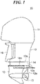
- FIG. 1 is an external view schematically illustrating a configuration of an outboard motor according to an preferred embodiment.
- FIG. 1 is an external view schematically illustrating a basic example of an outboard motor of the series of outboard motors according to the present teaching.
- an outboard motor 10 includes, as a casing enclosing various components, a cowl 11, a standard lower case 12, an uppercase 13, and an attachment 14 (intermediate structure).
- the cowl 11 encloses an engine (not illustrated) as a drive source
- the standard lower case 12 includes a propeller 15 as a propulsor and encloses a propeller shaft 40 (propeller shaft) for rotating the propeller 15.
- the upper case 13 encloses a drive shaft 27 that transmits a driving force (power) of the engine to the propeller shaft 40.
- a high-durability lower case 17 or a high-speed lower case 19 is attached instead of the standard lower case 12.
- the outboard motors 10 as illustrated in FIGS. 2A and 2B relates to examples of an outboard motor of the series of outboard motors according to the present teaching.
- the high-durability lower case 17 and the high-speed lower case 19 are different in shape from the standard lower case 12, neither a mating surface 17a of the high-durability lower case 17 nor a mating surface 19a of the high-speed lower case 19 matches the lower mating surface 14b of the attachment 14.
- an attachment 18 ( FIG. 2A ) having a lower mating surface 18b matching the mating surface 17a of the high-durability lower case 17 is used.
- An upper mating surface 18a of the attachment 18 is formed in the same shape as the upper mating surface 14a of the attachment 14. Accordingly, the attachment 18 can attach to the high-durability lower case 17 and to the upper case 13, and thus can connect the upper case 13 and the high-durability lower case 17.
- an attachment 20 ( FIG. 2B ) having a lower mating surface 20b matching the mating surface 19a of the high-speed lower case 19 is used.
- An upper mating surface 20a of the attachment 20 is formed in the same shape as the upper mating surface 14a of the attachment 14. Accordingly, the attachment 20 can attach to the high-speed lower case 19 and to the upper case 13, and thus can connect the upper case 13 and the high-speed lower case 19.
- the upper case 13 includes a frame body 21 and a resin cover 38 that covers the frame body 21.
- the frame body 21 is made of metal, for example, aluminum, and is fastened to the attachment 14 and the suspension mechanism 16.
- a propulsive force generated by the propeller 15 is transmitted to the hull via the standard lower case 12, the attachment 14, the frame body 21, and the suspension mechanism 16.
- the upper case 13 may include a case-shaped main body 39 formed by a rigid body made of metal, for example, aluminum, and a cover (not illustrated) that improves an appearance of the main body 39, instead of the frame body 21 and the cover 38, and the case-shaped main body 39 may be fastened to the attachment 14 and the suspension mechanism 16.
- the case-shaped main body 39 transmits the propulsive force generated by the propeller 15 to the hull.
- the attachment 14 is configured to connect the upper case 13 and the standard lower case 12, when the high-durability lower case 17 or the high-speed lower case 19 are attached to the upper case 13, provided that the attachment 18 connectable to the mating surface 17a of the high-durability lower case 17 or the attachment 20 connectable to the mating surface 19a of the high-speed lower case 19 is used instead of the attachment 14, the high-durability lower case 17 or the high-speed lower case 19 can be attached to the upper case 13. Accordingly, it is possible to eliminate the need to newly manufacture the upper case 13 when the high-durability lower case 17 or the high-speed lower case 19 to be attached is desired, and it is possible to suppress an increase in the number of types of the upper case 13.
- the outboard motor 10 since the outboard motor 10 has the frame body 21 or the case-shaped main body 39 formed by rigid body, which is fastened to the attachment 14 and the suspension mechanism 16, the propulsive force generated by the propeller 15 can be reliably transmitted to the hull via the attachment 14 and the suspension mechanism 16.
- the lower case encloses a gearbox that engages with the drive shaft to transmit the rotation of the drive shaft to the propeller shaft, and a link mechanism that switches between rotation directions of the propeller.
- a shift rod is connected to the link mechanism, and the shift rod is disposed parallel to the drive shaft and is rotated or moved up and down by a shift actuator.
- the link mechanism moves a dog clutch in the gearbox via a shift slider in accordance with the movement of the shift rod, and thereby the link mechanism switches between the rotation directions of the propeller.
- the link mechanism, the shift rod, and the shift actuator constitute a shift mechanism.
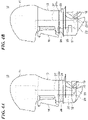
- FIGS. 4A and 4B are external views schematically illustrating a configuration of an outboard motor according to the first variation of the preferred embodiment.
- FIGS. 4A and 4B are external views schematically illustrating examples of an outboard motor of the series of outboard motors according to the present teaching.
- the present variation presents attachments 24 and 25 respectively corresponding to the standard lower case 12 and the high-durability lower case 17.
- a shape of an upper mating surface 24a of the attachment 24 is the same as a shape of an upper mating surface 25a of the attachment 25.
- the changed lower case can be attached to the same upper case by replacing the attachment. That is, it is possible to eliminate the need to newly manufacture the upper case 13, and to suppress the increase in the number of types of the upper case 13.
- the shift actuator 28 may be configured to be movable in the attachment so that the position of the shift actuator 28 can be changed in accordance with the interval between the link mechanism 22 and the gearbox 23 in each lower case. In this case, it is possible to eliminate the need to newly manufacture the attachment, which suppresses the increase in the number of types of attachments.
- the lower case in the hybrid outboard motor encloses a motor gearbox for transmitting a driving force of the electric motor to the propeller shaft in addition to the link mechanism and the gearbox which engages with the drive shaft for transmitting the driving force of the engine.
- the electric motor is disposed in the lower case in the hybrid outboard motor described in JP 2020-29186 A ; however, since the shape of the lower case greatly affects sailing performance of the marine vessel, the electric motor that affects the shape of the lower case is preferably disposed in the upper case. Therefore, when the outboard motor is hybridized, it may be necessary to manufacture not only the lower case but also the upper case and newly dispose the electric motor in the upper case.
- the standard lower case 12 encloses the link mechanism 22 and the gearbox 23 but does not enclose a gearbox for a motor ( FIG. 5A ).
- a hybrid-compatible lower case 30 encloses not only a link mechanism 22 and a gearbox 23 but also a gearbox for a motor (a motor gearbox 31) ( FIG. 5B ).
- a hybrid-compatible attachment 32 encloses an electric motor 33, and the electric motor 33 is connected to the motor gearbox 31 via a motor drive shaft 34.
- a propeller 15 is driven by an engine or the electric motor 33.
- a shape of an upper mating surface 32a of the hybrid-compatible attachment 32 is the same as a shape of an upper mating surface 24a of an attachment 24.
- the electric motor 33 is disposed so as to face the motor gearbox 31.
- the hybrid-compatible lower case 30 can be attached to the upper case 13 only by replacing the attachment 24 with the hybrid-compatible attachment 32. Accordingly, it is possible to eliminate the need to newly manufacture the upper case 13 in order to hybridized the outboard motor, and it is possible to suppress the increase in the number of types of the upper cases 13.
- the electric motor 33 is enclosed in the hybrid-compatible attachment 32, and thus, it is possible to eliminate the need to arrange the electric motor 33 in the hybrid-compatible lower case 30, which makes it possible to prevent the shape of the hybrid-compatible lower case 30 from being hydrodynamically disadvantageous. As a result, even though the outboard motor is hybridized, it is possible to suppress significant influence on the sailing performance of the marine vessel.
- hybrid-compatible lower case 30 a high-durability hybrid-compatible lower case or a high-speed hybrid-compatible lower case may be used.
- the relative position of the motor gearbox 31 with respect to the link mechanism 22 and the gearbox 23 may change.
- the electric motor 33 may be configured to be movable in the hybrid-compatible attachment 32, so that the position of the electric motor 33 may be changed in accordance with the relative position of the motor gearbox 31 with respect to the link mechanism 22 and the gearbox 23 in each lower case.
- a plurality of hybrid-compatible attachments in which the electric motor 33 is disposed at the position corresponding to the relative position of the motor gearbox 31 with respect to the link mechanism 22 and the gearbox 23 in each lower case may be prepared, and the hybrid-compatible attachment corresponding to each lower case may be used.
- a splash plate for preventing the splashes from scattering may be provided in the upper case conventionally.
- a scattering form of the splashes changes in accordance with the shape of the lower case.
- the standard lower case 12 is replaced with the high-durability lower case 17 or the high-speed lower case 19, it may be necessary to change the shape of the splash plate in accordance with the scattering form of the splashes in each case, and it may be necessary to newly manufacture the upper case.
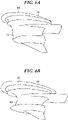
- FIGS. 6A and 6B are external perspective views schematically illustrating a configuration of an attachment of an outboard motor according to the third variation of the preferred embodiment.
- FIGS. 6A and 6B are external views schematically illustrating examples of an outboard motor of the series of outboard motors according to the present teaching.
- a splash plate 35 is formed at an upper portion of an attachment 14 attached to a standard lower case 12 ( FIG. 6A ), and a splash plate 36 is formed at an upper portion of an attachment 20 attached to a high-speed lower case 19 ( FIG. 6B ).
- the splash plate 35 and the splash plate 36 have different shapes. Specifically, since the amount of splashes increases when the high-speed lower case 19 is used, the splash plate 36 is formed to be larger than the splash plate 35.
- the splash plate can be also formed at an upper portion of an attachment 18 attached to a high-durability lower case 17, wherein a shape of this splash plate is also different from shapes of the splash plates 35 and 36.
- the splash plate suitable for the changed scattering form of the splashes can be used by replacing the attachment. That is, it is possible to eliminate the need to replace the upper case in order to change the shape of the splash plate, and thus, it is possible to eliminate the need to newly manufacture the upper case 13.
- Each splash plate may be formed integrally with each attachment, or may be formed to be replaceable with respect to each attachment.
- each splash plate is formed to be replaceable with respect to each attachment, provided that the shapes of the mating surfaces of the lower cases are the same, the scattering of the splashes can be prevented by replacing only the splash plate without changing the attachment in accordance with the change of the lower case. Accordingly, it is possible to save a time and an effort for replacing the attachment.
- a sacrificial anode is provided in the suspension mechanism and the lower case.
- a sacrificial anode 37 is provided in the attachment 14.
- the sacrificial anode 37 is provided at a position ( FIG. 7A ) at which navigation waves or splashes are applied while the marine vessel sails, or a position ( FIG. 7B ) at which the marine vessel sinks under the water surface even when the outboard motor 10 is tilted up during storage of the marine vessel.
- the present teaching is applied to an outboard motor.
- the present teaching may be applied to the inboard/outboard motor including the upper case and the lower case.
- an inboard/outboard motor includes an attachment, and the attachment connects the lower case and the upper case.
Landscapes
- Chemical & Material Sciences (AREA)
- Engineering & Computer Science (AREA)
- Combustion & Propulsion (AREA)
- Mechanical Engineering (AREA)
- Ocean & Marine Engineering (AREA)
- General Details Of Gearings (AREA)
- Connection Of Motors, Electrical Generators, Mechanical Devices, And The Like (AREA)
Abstract
Description
- The present invention relates to a series of outboard motors and a marine vessel equipped with an outboard motor of the series of outboard motors.
- In the related art, as shown in
FIGS. 8A to 8C , anoutboard motor 80 includes alower case 82 having apropeller 81 as a propulsor, and anupper case 83 having a drive shaft that transmits a driving force of an engine as a drive source to the propeller (see, for example,JP 2020-29186 A lower case 82 and theupper case 83 are manufactured via die-casting aluminum, thelower case 82 being attached to theupper case 83 so that amating surface 82a of thelower case 82 is connected to amating surface 83a of theupper case 83. - Incidentally, since the
lower case 82 sinks under a water surface when a marine vessel sails, which significantly affects on sailing performance of the marine vessel. In recent years, the use of the marine vessel has been diversified, and the sailing performance required for the marine vessel has also been diversified, and various types of lower cases corresponding to the sailing performance are manufactured. The lower case is changed (modified) in design in accordance with the required sailing performance, and the changed lower case is attached to theupper case 83. - Incidentally, when the lower case is changed, shapes of the lower case before and after the change may be different. For example, in a case of a lower case having high-durability, the high-durability
lower case 84 is designed by being increased in size in order to accommodate drive components having a lifespan twice or more that of a typicallower case 82, on the assumption of use for a longer period of time than the normal lower case 82 (FIG. 8B ). In a case of a high-speed lower case, a high-speedlower case 85 is designed by being miniaturized so as to be smaller than the typicallower case 82 in order to reduce resistance (FIG. 8C ). That is, the high-durabilitylower case 84 and the high-speedlower case 85 are each different in shape from thelower case 82. - Accordingly, as shown in
FIGS. 8B and 8C , themating surface 83a of theupper case 83 does not match amating surface 84a of thelower case 84 or amating surface 85a of thelower case 85, and which may be difficult to attach the high-durabilitylower case 84 or the high-speedlower case 85 to theupper case 83. - In this case, it is necessary to newly manufacture an upper case having a mating surface matching the
mating surface 84a of the high-durabilitylower case 84 or themating surface 85a of the high-speedlower case 85, and therefore there is room for improvement from the viewpoint of reducing the number of components and shortening a development period of the outboard motor. - An object of the present invention is to provide a series of outboard motors that can suppress an increase in the number of types of upper cases and to provide and a marine vessel equipped with an outboard motor of the series of outboard motors.
- According to the present invention said object is solved by a series of outboard motors according to the independent claim 1. Preferred embodiments are laid down in the dependent claims. Moreover, according to the present invention said object is solved by a marine vessel equipped with an outboard motor of the series of outboard motors according to
claim 10. - According to a preferred embodiment, an outboard motor attached to a hull of a marine vessel, the outboard motor comprising: a lower case that includes a propeller shaft configured to rotate a propeller; and an upper case that includes a drive shaft configured to transmit a power to the propeller shaft, wherein the lower case is selected from among a plurality of types of lower cases, and is configured to be attached to the upper case, and the upper case and the lower case are connected by an intermediate structure.
- According to this configuration, the intermediate structure connects the upper case and the lower case, which makes it possible to attach, by using the intermediate structure connectable to the mating surface having the shape changed when the lower case in which the shape of the mating surface is changed is attached to the upper case, the lower case having the changed shape to the upper case via the intermediate structure without newly manufacturing the upper case. As a result, it is possible to suppress the increase in the number of types of upper cases.
- Further features of the present teaching will become apparent from the following description of exemplary embodiments with reference to the attached drawings.
- The above and other elements, features, steps, characteristics and advantages of the present teaching will become more apparent from the following detailed description of the preferred embodiments with reference to the attached drawings.
-
-
FIG. 1 is an external view schematically illustrating a configuration of an outboard motor according to a preferred embodiment. -
FIGS. 2A and 2B are diagrams for describing attachments corresponding to various lower cases. -
FIGS. 3A and 3B are diagrams for describing a mechanism for transmitting a propulsive force of a propeller to a hull of a marine vessel. -
FIGS. 4A and 4B are external views schematically illustrating a configuration of an outboard motor according to a first variation of the preferred embodiment. -
FIGS. 5A and 5B are external views schematically illustrating a configuration of an outboard motor according to a second variation of the preferred embodiment. -
FIGS. 6A and 6B are external perspective views schematically illustrating a configuration of an attachment of an outboard motor according to a third variation of the preferred embodiment. -
FIGS. 7A and 7B are diagrams for describing an arrangement form of sacrificial anodes in the embodiments and each variation of the present invention. -
FIGS. 8A to 8C are diagrams for describing a problem associated with a change of a lower case in an outboard motor of the related art. - Hereinafter, preferred embodiments of the present teaching will be described with reference to the drawings.
-
FIG. 1 is an external view schematically illustrating a configuration of an outboard motor according to an preferred embodiment.FIG. 1 is an external view schematically illustrating a basic example of an outboard motor of the series of outboard motors according to the present teaching. Referring toFIG. 1 , anoutboard motor 10 includes, as a casing enclosing various components, acowl 11, a standardlower case 12, anuppercase 13, and an attachment 14 (intermediate structure). Thecowl 11 encloses an engine (not illustrated) as a drive source, and the standardlower case 12 includes apropeller 15 as a propulsor and encloses a propeller shaft 40 (propeller shaft) for rotating thepropeller 15. Theupper case 13 encloses adrive shaft 27 that transmits a driving force (power) of the engine to thepropeller shaft 40. - In addition, the
outboard motor 10 includes asuspension mechanism 16 for attaching theoutboard motor 10 to a stern (not illustrated) of a hull of the marine vessel, and thesuspension mechanism 16 functions as a steering mechanism and a lifting mechanism of theoutboard motor 10 and tilts up theoutboard motor 10 when the marine vessel is stored. - The
attachment 14 is interposed between the standardlower case 12 and theupper case 13, to connect the standardlower case 12 and theupper case 13. A shape of anupper mating surface 14a of theattachment 14 is formed so as to match amating surface 13a of theupper case 13, and a shape of alower mating surface 14b of theattachment 14 is formed so as to match amating surface 12a of the standardlower case 12. - Incidentally, in the
outboard motor 10, as illustrated inFIGS. 2A and 2B , in some cases a high-durabilitylower case 17 or a high-speedlower case 19 is attached instead of the standardlower case 12. In particular, in theoutboard motors 10, as illustrated inFIGS. 2A and 2B , relates to examples of an outboard motor of the series of outboard motors according to the present teaching. However, since the high-durabilitylower case 17 and the high-speedlower case 19 are different in shape from the standardlower case 12, neither amating surface 17a of the high-durabilitylower case 17 nor amating surface 19a of the high-speedlower case 19 matches thelower mating surface 14b of theattachment 14. - On the other hand, in the present embodiment, an attachment 18 (
FIG. 2A ) having alower mating surface 18b matching themating surface 17a of the high-durabilitylower case 17 is used. Anupper mating surface 18a of theattachment 18 is formed in the same shape as theupper mating surface 14a of theattachment 14. Accordingly, theattachment 18 can attach to the high-durabilitylower case 17 and to theupper case 13, and thus can connect theupper case 13 and the high-durabilitylower case 17. - In the present embodiment, an attachment 20 (
FIG. 2B ) having alower mating surface 20b matching themating surface 19a of the high-speedlower case 19 is used. Anupper mating surface 20a of theattachment 20 is formed in the same shape as theupper mating surface 14a of theattachment 14. Accordingly, theattachment 20 can attach to the high-speedlower case 19 and to theupper case 13, and thus can connect theupper case 13 and the high-speedlower case 19. - Further, for example, as illustrated in
FIG. 3A , theupper case 13 includes aframe body 21 and aresin cover 38 that covers theframe body 21. Theframe body 21 is made of metal, for example, aluminum, and is fastened to theattachment 14 and thesuspension mechanism 16. A propulsive force generated by thepropeller 15 is transmitted to the hull via the standardlower case 12, theattachment 14, theframe body 21, and thesuspension mechanism 16. Furthermore, for example, as illustrated inFIG. 3B , theupper case 13 may include a case-shapedmain body 39 formed by a rigid body made of metal, for example, aluminum, and a cover (not illustrated) that improves an appearance of themain body 39, instead of theframe body 21 and thecover 38, and the case-shapedmain body 39 may be fastened to theattachment 14 and thesuspension mechanism 16. In this case, instead of theframe body 21, the case-shapedmain body 39 transmits the propulsive force generated by thepropeller 15 to the hull. - According to the present embodiment, since the
attachment 14 is configured to connect theupper case 13 and the standardlower case 12, when the high-durabilitylower case 17 or the high-speedlower case 19 are attached to theupper case 13, provided that theattachment 18 connectable to themating surface 17a of the high-durabilitylower case 17 or theattachment 20 connectable to themating surface 19a of the high-speedlower case 19 is used instead of theattachment 14, the high-durabilitylower case 17 or the high-speedlower case 19 can be attached to theupper case 13. Accordingly, it is possible to eliminate the need to newly manufacture theupper case 13 when the high-durabilitylower case 17 or the high-speedlower case 19 to be attached is desired, and it is possible to suppress an increase in the number of types of theupper case 13. - In addition, in the present embodiment, since the
outboard motor 10 has theframe body 21 or the case-shapedmain body 39 formed by rigid body, which is fastened to theattachment 14 and thesuspension mechanism 16, the propulsive force generated by thepropeller 15 can be reliably transmitted to the hull via theattachment 14 and thesuspension mechanism 16. - Incidentally, in typical, the lower case encloses a gearbox that engages with the drive shaft to transmit the rotation of the drive shaft to the propeller shaft, and a link mechanism that switches between rotation directions of the propeller. A shift rod is connected to the link mechanism, and the shift rod is disposed parallel to the drive shaft and is rotated or moved up and down by a shift actuator. The link mechanism moves a dog clutch in the gearbox via a shift slider in accordance with the movement of the shift rod, and thereby the link mechanism switches between the rotation directions of the propeller. The link mechanism, the shift rod, and the shift actuator constitute a shift mechanism.
- In the related art, although a shift actuator is enclosed in an upper case or a cowl, an interval between a link mechanism and a gearbox may vary in accordance with a type of a lower case, and thus, a relative position (pitch) of a shift rod with respect to a drive shaft may change. As a result, when the lower case is changed and attached, it may be necessary to newly manufacture the upper case in order to change the pitch between the shift rod and the drive shaft by changing the position of the shift actuator.
- On the other hand, in a first variation of the preferred embodiment, the shift actuator is disposed in the attachment.
FIGS. 4A and 4B are external views schematically illustrating a configuration of an outboard motor according to the first variation of the preferred embodiment.FIGS. 4A and 4B are external views schematically illustrating examples of an outboard motor of the series of outboard motors according to the present teaching. For example, there are some cases where an interval between theenclosed link mechanism 22 andgearbox 23 is different, between the standardlower case 12 and the high-durabilitylower case 17. The present variation presentsattachments lower case 12 and the high-durabilitylower case 17. A shape of anupper mating surface 24a of theattachment 24 is the same as a shape of anupper mating surface 25a of theattachment 25. - In the
attachment 24, a position of ashift actuator 28 is set such that a pitch between ashift rod 26 and a drive shaft 27 (drive shaft) corresponds to an interval between thelink mechanism 22 and thegearbox 23 in the standard lower case 12 (FIG. 4A ). Similarly, in theattachment 25, a position of theshift actuator 28 is set such that a pitch between theshift rod 26 and thedrive shaft 27 corresponds to an interval between thelink mechanism 22 and thegearbox 23 in the high-durability lower case 17 (FIG. 4B ). It should be noted that when the interval between thelink mechanism 22 and thegearbox 23 enclosed in the high-speedlower case 19 is different from the interval between thelink mechanism 22 and thegearbox 23 enclosed in the standardlower case 12 or the high-durabilitylower case 17, an attachment in which the position of theshift actuator 28 is set such that the pitch between theshift rod 26 and thedrive shaft 27 corresponds to the interval between thelink mechanism 22 and thegearbox 23 in the high-speedlower case 19 is used. - Accordingly, even though the interval between the link mechanism and the gearbox is different among different the types of the lower case, the changed lower case can be attached to the same upper case by replacing the attachment. That is, it is possible to eliminate the need to newly manufacture the
upper case 13, and to suppress the increase in the number of types of theupper case 13. - It should be noted that, although a plurality of types of attachments in which the position of the
shift actuator 28 is changed in accordance with the type of the lower case is used in the present variation, in a case where the shapes of the mating surfaces of the various lower cases is not changed, theshift actuator 28 may be configured to be movable in the attachment so that the position of theshift actuator 28 can be changed in accordance with the interval between thelink mechanism 22 and thegearbox 23 in each lower case. In this case, it is possible to eliminate the need to newly manufacture the attachment, which suppresses the increase in the number of types of attachments. - In addition, in recent years, it has been studied, in the outboard motor, to drive the propeller not only by the engine which is an internal combustion engine but also by the electric motor, and the present applicant has proposed, for example, a hybrid outboard motor including an engine and an electric motor (see, for example,
JP 2020-29186 A - Incidentally, the lower case in the hybrid outboard motor encloses a motor gearbox for transmitting a driving force of the electric motor to the propeller shaft in addition to the link mechanism and the gearbox which engages with the drive shaft for transmitting the driving force of the engine. The electric motor is disposed in the lower case in the hybrid outboard motor described in
JP 2020-29186 A - Regarding this matter, in a second variation of the preferred embodiment, the electric motor is disposed in the attachment.
FIGS. 5A and 5B are external views schematically illustrating a configuration of an outboard motor according to the second variation of the preferred embodiment.FIGS. 5A and 5B are external views schematically illustrating examples of an outboard motor of the series of outboard motors according to the present teaching. - In the
outboard motor 10 which is not hybridized and in which thepropeller 15 is driven only by an engine, as described above, the standardlower case 12 encloses thelink mechanism 22 and thegearbox 23 but does not enclose a gearbox for a motor (FIG. 5A ). On the other hand, in a hybridoutboard motor 29, a hybrid-compatiblelower case 30 encloses not only alink mechanism 22 and agearbox 23 but also a gearbox for a motor (a motor gearbox 31) (FIG. 5B ). In this case, a hybrid-compatible attachment 32 encloses an electric motor 33, and the electric motor 33 is connected to themotor gearbox 31 via amotor drive shaft 34. With this configuration, in the hybridoutboard motor 29 having the hybrid-compatible attachment 32, apropeller 15 is driven by an engine or the electric motor 33. A shape of anupper mating surface 32a of the hybrid-compatible attachment 32 is the same as a shape of anupper mating surface 24a of anattachment 24. In the hybrid-compatible attachment 32, the electric motor 33 is disposed so as to face themotor gearbox 31. - Accordingly, when the standard
lower case 12 is replaced with the hybrid-compatiblelower case 30 in order to hybridize the outboard motor, the hybrid-compatiblelower case 30 can be attached to theupper case 13 only by replacing theattachment 24 with the hybrid-compatible attachment 32. Accordingly, it is possible to eliminate the need to newly manufacture theupper case 13 in order to hybridized the outboard motor, and it is possible to suppress the increase in the number of types of theupper cases 13. - In addition, the electric motor 33 is enclosed in the hybrid-
compatible attachment 32, and thus, it is possible to eliminate the need to arrange the electric motor 33 in the hybrid-compatiblelower case 30, which makes it possible to prevent the shape of the hybrid-compatiblelower case 30 from being hydrodynamically disadvantageous. As a result, even though the outboard motor is hybridized, it is possible to suppress significant influence on the sailing performance of the marine vessel. - Instead of the hybrid-compatible
lower case 30, a high-durability hybrid-compatible lower case or a high-speed hybrid-compatible lower case may be used. In this case, the relative position of themotor gearbox 31 with respect to thelink mechanism 22 and thegearbox 23 may change. Regarding this matter, the electric motor 33 may be configured to be movable in the hybrid-compatible attachment 32, so that the position of the electric motor 33 may be changed in accordance with the relative position of themotor gearbox 31 with respect to thelink mechanism 22 and thegearbox 23 in each lower case. Alternatively, a plurality of hybrid-compatible attachments in which the electric motor 33 is disposed at the position corresponding to the relative position of themotor gearbox 31 with respect to thelink mechanism 22 and thegearbox 23 in each lower case may be prepared, and the hybrid-compatible attachment corresponding to each lower case may be used. - In the outboard motor, since at least a part of the lower case is submerged and makes splashes while the marine vessel sails, a splash plate (anti-splash plate) for preventing the splashes from scattering may be provided in the upper case conventionally.
- Incidentally, a scattering form of the splashes changes in accordance with the shape of the lower case. Thus, for example, when the standard
lower case 12 is replaced with the high-durabilitylower case 17 or the high-speedlower case 19, it may be necessary to change the shape of the splash plate in accordance with the scattering form of the splashes in each case, and it may be necessary to newly manufacture the upper case. - Regarding this matter, in a third variation of the preferred embodiment, a splash plate is formed on an attachment.
FIGS. 6A and 6B are external perspective views schematically illustrating a configuration of an attachment of an outboard motor according to the third variation of the preferred embodiment.FIGS. 6A and 6B are external views schematically illustrating examples of an outboard motor of the series of outboard motors according to the present teaching. - In the present variation, for example, a
splash plate 35 is formed at an upper portion of anattachment 14 attached to a standard lower case 12 (FIG. 6A ), and asplash plate 36 is formed at an upper portion of anattachment 20 attached to a high-speed lower case 19 (FIG. 6B ). Thesplash plate 35 and thesplash plate 36 have different shapes. Specifically, since the amount of splashes increases when the high-speedlower case 19 is used, thesplash plate 36 is formed to be larger than thesplash plate 35. The splash plate can be also formed at an upper portion of anattachment 18 attached to a high-durabilitylower case 17, wherein a shape of this splash plate is also different from shapes of thesplash plates - Accordingly, even in a case where the lower case is replaced and the scattering form of the splashes changes, the splash plate suitable for the changed scattering form of the splashes can be used by replacing the attachment. That is, it is possible to eliminate the need to replace the upper case in order to change the shape of the splash plate, and thus, it is possible to eliminate the need to newly manufacture the
upper case 13. - Each splash plate may be formed integrally with each attachment, or may be formed to be replaceable with respect to each attachment. In a case where each splash plate is formed to be replaceable with respect to each attachment, provided that the shapes of the mating surfaces of the lower cases are the same, the scattering of the splashes can be prevented by replacing only the splash plate without changing the attachment in accordance with the change of the lower case. Accordingly, it is possible to save a time and an effort for replacing the attachment.
- Conventionally, in order to suppress the progress of corrosion of each part of the
outboard motor 10, a sacrificial anode is provided in the suspension mechanism and the lower case. Regarding this matter, in the above-described embodiments/variations, asacrificial anode 37 is provided in theattachment 14. Specifically, in theattachment 14, thesacrificial anode 37 is provided at a position (FIG. 7A ) at which navigation waves or splashes are applied while the marine vessel sails, or a position (FIG. 7B ) at which the marine vessel sinks under the water surface even when theoutboard motor 10 is tilted up during storage of the marine vessel. With this configuration, thesacrificial anode 37 can be reliably brought into contact with the water, and thus, the progress of the corrosion of each part of theoutboard motor 10 can be suppressed. - According to the embodiment, the present teaching is applied to an outboard motor. However, the present teaching may be applied to the inboard/outboard motor including the upper case and the lower case. Likewise in this case, an inboard/outboard motor includes an attachment, and the attachment connects the lower case and the upper case.
Claims (11)
- A series of outboard motors (10) configured to be attached to a hull of a marine vessel, an outboard motor (10) of the series of outboard motors (10) comprises an upper case (13) that includes a drive shaft (27) configured to transmit a power to a propeller shaft (40) and the series of outboard motors (10) comprisesa plurality of types of lower cases (12, 17, 19),each of the plurality of lower case (12, 17, 19) is configured to include the propeller shaft (40) configured to rotate the propeller (15);each of the plurality of lower case (12, 17, 19) is configured to be attached to the upper case(13), whereinone lower case is selected from among the plurality of types of lower cases (12, 17, 19), and the upper case (13) and the lower case (12, 17, 19) as selected are connected by an intermediate structure (14, 18, 20).
- The series of outboard motors (10) according to claim 1, wherein the intermediate structure (14, 18, 20) includes a shift mechanism that is configured to switch between rotation directions of the propeller (15), and each outboard motor (10) of the series of outboard motors (10) is configured to have a relative position of the shift mechanism to the drive shaft (27) changeable.
- The series of outboard motors (10) according to claim 2, wherein the shift mechanism includes at least one of a shift rod (26) for switching between the rotation directions of the propeller (15) and an actuator (28) for moving the shift rod (26), and
a relative position of the shift rod (26) to the drive shaft (27) is changeable. - The series of outboard motors (10) according to claim 1, wherein the intermediate structure (14, 18, 20) includes an electric motor (33), and
the electric motor (33) is configured to drive the propeller (15). - The series of outboard motors (10) according to claim 1, wherein at least a part of the lower case (12, 17, 19) is configured to be submerged and configured to make splashes while the marine vessel sails,the intermediate structure (14, 18, 20) includes an anti-splash plate (35, 36) configured for suppressing scattering of the splashes, anda shape of the anti-splash plate (35, 36) is changed in accordance with a shape of the lower case among the plurality of types of lower cases (12, 17, 19).
- The series of outboard motors (10) according to claim 5, wherein the anti-splash plate (35, 36) is configured to be replaceable with respect to the intermediate structure (14, 18, 20).
- The series of outboard motors (10) according to claim 1, wherein at least a part of the intermediate structure (14, 18, 20) is configured to be submerged when the outboard motor (10) is tilted up, and
a sacrificial anode (37) is disposed at the submerged position of the intermediate structure (14, 18, 20). - The series of outboard motors (10) according to claim 1, wherein the upper case (13) includes a frame body (21) and a cover (38) that covers the frame body (21), and
the frame body (21) is configured to transmit a propulsive force generated by the propeller (15) to the hull of the marine vessel. - The series of outboard motors (10) according to claim 1, wherein the upper case (13) includes a case-shaped main body (39), and
the case-shaped main body (39) is configured to transmit a propulsive force generated by the propeller (15) to the hull of the marine vessel. - A marine vessel equipped with an outboard motor (10) of the series of outboard motors (10) according to at least one of the claims 1 to 9 and attached to a hull of the marine vessel.
- A marine propulsion device configured to be attached to a hull of a marine vessel, the marine propulsion device comprises an outboard motor of a series of outboard motors (10) according to at least one of the claims 1 to 9.
Applications Claiming Priority (1)
| Application Number | Priority Date | Filing Date | Title |
|---|---|---|---|
| JP2021008737A JP2022112788A (en) | 2021-01-22 | 2021-01-22 | Outboard engine, ship, and ship propeller |
Publications (2)
| Publication Number | Publication Date |
|---|---|
| EP4032798A1 true EP4032798A1 (en) | 2022-07-27 |
| EP4032798B1 EP4032798B1 (en) | 2025-04-30 |
Family
ID=79025208
Family Applications (1)
| Application Number | Title | Priority Date | Filing Date |
|---|---|---|---|
| EP21218135.8A Active EP4032798B1 (en) | 2021-01-22 | 2021-12-29 | Series of outboard motors and marine vessel |
Country Status (3)
| Country | Link |
|---|---|
| US (1) | US12097942B2 (en) |
| EP (1) | EP4032798B1 (en) |
| JP (1) | JP2022112788A (en) |
Citations (6)
| Publication number | Priority date | Publication date | Assignee | Title |
|---|---|---|---|---|
| US6814635B1 (en) * | 2002-01-25 | 2004-11-09 | Yamaha Marine Kabushiki Kaisha | Vertically extendable arrangement for marine propulsion device |
| US20130273792A1 (en) * | 2010-02-11 | 2013-10-17 | Davis Engineering, Llc | Large outboard motor including variable gear transfer case |
| US20160001867A1 (en) * | 2014-07-01 | 2016-01-07 | Yamaha Hatsudoki Kabushiki Kaisha | Spacer case for outboard motor and outboard motor |
| EP3613663A1 (en) * | 2018-08-23 | 2020-02-26 | Yamaha Hatsudoki Kabushiki Kaisha | Hybrid type vessel propulsion apparatus |
| JP2020029186A (en) | 2018-08-23 | 2020-02-27 | ヤマハ発動機株式会社 | Hybrid-type ship propulsion machine |
| US20200130801A1 (en) * | 2018-10-26 | 2020-04-30 | Yamaha Hatsudoki Kabushiki Kaisha | Outboard motor and method of manufacturing shaft for outboard motor |
Family Cites Families (1)
| Publication number | Priority date | Publication date | Assignee | Title |
|---|---|---|---|---|
| WO2011100641A1 (en) * | 2010-02-11 | 2011-08-18 | Davis Engineering, Llc | Large outboard motor for marine vessel application and related methods of making and operating same |
-
2021
- 2021-01-22 JP JP2021008737A patent/JP2022112788A/en active Pending
- 2021-12-29 EP EP21218135.8A patent/EP4032798B1/en active Active
-
2022
- 2022-01-05 US US17/568,885 patent/US12097942B2/en active Active
Patent Citations (6)
| Publication number | Priority date | Publication date | Assignee | Title |
|---|---|---|---|---|
| US6814635B1 (en) * | 2002-01-25 | 2004-11-09 | Yamaha Marine Kabushiki Kaisha | Vertically extendable arrangement for marine propulsion device |
| US20130273792A1 (en) * | 2010-02-11 | 2013-10-17 | Davis Engineering, Llc | Large outboard motor including variable gear transfer case |
| US20160001867A1 (en) * | 2014-07-01 | 2016-01-07 | Yamaha Hatsudoki Kabushiki Kaisha | Spacer case for outboard motor and outboard motor |
| EP3613663A1 (en) * | 2018-08-23 | 2020-02-26 | Yamaha Hatsudoki Kabushiki Kaisha | Hybrid type vessel propulsion apparatus |
| JP2020029186A (en) | 2018-08-23 | 2020-02-27 | ヤマハ発動機株式会社 | Hybrid-type ship propulsion machine |
| US20200130801A1 (en) * | 2018-10-26 | 2020-04-30 | Yamaha Hatsudoki Kabushiki Kaisha | Outboard motor and method of manufacturing shaft for outboard motor |
Also Published As
| Publication number | Publication date |
|---|---|
| US12097942B2 (en) | 2024-09-24 |
| US20220234706A1 (en) | 2022-07-28 |
| JP2022112788A (en) | 2022-08-03 |
| EP4032798B1 (en) | 2025-04-30 |
Similar Documents
| Publication | Publication Date | Title |
|---|---|---|
| US7485018B2 (en) | Marine drive system | |
| JP7809938B2 (en) | Hybrid marine propulsion unit | |
| JP2023131734A (en) | Outboard motors and ships | |
| JP2013052745A (en) | Submersible vessel | |
| US20060172630A1 (en) | Marine vessel propulsion structure and marine vessel driving apparatus | |
| US20210024193A1 (en) | Outboard motor | |
| KR20230005299A (en) | get on | |
| US12358602B2 (en) | Hybrid ship propulsion machine | |
| EP4032798B1 (en) | Series of outboard motors and marine vessel | |
| US11260947B2 (en) | Outboard motor and marine vessel | |
| JP2024060160A (en) | Marine propulsion system and vessel | |
| JPWO2011061963A1 (en) | Electric ship | |
| US12420899B2 (en) | Marine propulsion system and marine vessel | |
| JP2023044488A (en) | Hybrid ship propeller | |
| EP4299434A1 (en) | Propulsion device for marine vessel, outboard motor and marine vessel | |
| US11161583B2 (en) | Marine propulsion unit | |
| JP2017052326A (en) | Outboard engine | |
| JPH10119892A (en) | Outboard engine | |
| EP1925350A1 (en) | On-water/underwater movable toy | |
| HU231702B1 (en) | Replacement propeller unit | |
| US20220111946A1 (en) | Outboard motor | |
| CN219428314U (en) | Dual-mode small waterplane ship | |
| JP2006182043A (en) | Ship with pod propeller | |
| US12491978B2 (en) | Marine propulsion device with simplified wiring of power lines | |
| US9994295B2 (en) | Outboard motor |
Legal Events
| Date | Code | Title | Description |
|---|---|---|---|
| PUAI | Public reference made under article 153(3) epc to a published international application that has entered the european phase |
Free format text: ORIGINAL CODE: 0009012 |
|
| STAA | Information on the status of an ep patent application or granted ep patent |
Free format text: STATUS: THE APPLICATION HAS BEEN PUBLISHED |
|
| AK | Designated contracting states |
Kind code of ref document: A1 Designated state(s): AL AT BE BG CH CY CZ DE DK EE ES FI FR GB GR HR HU IE IS IT LI LT LU LV MC MK MT NL NO PL PT RO RS SE SI SK SM TR |
|
| STAA | Information on the status of an ep patent application or granted ep patent |
Free format text: STATUS: REQUEST FOR EXAMINATION WAS MADE |
|
| 17P | Request for examination filed |
Effective date: 20221115 |
|
| RBV | Designated contracting states (corrected) |
Designated state(s): AL AT BE BG CH CY CZ DE DK EE ES FI FR GB GR HR HU IE IS IT LI LT LU LV MC MK MT NL NO PL PT RO RS SE SI SK SM TR |
|
| STAA | Information on the status of an ep patent application or granted ep patent |
Free format text: STATUS: EXAMINATION IS IN PROGRESS |
|
| 17Q | First examination report despatched |
Effective date: 20240415 |
|
| GRAP | Despatch of communication of intention to grant a patent |
Free format text: ORIGINAL CODE: EPIDOSNIGR1 |
|
| STAA | Information on the status of an ep patent application or granted ep patent |
Free format text: STATUS: GRANT OF PATENT IS INTENDED |
|
| INTG | Intention to grant announced |
Effective date: 20250127 |
|
| GRAS | Grant fee paid |
Free format text: ORIGINAL CODE: EPIDOSNIGR3 |
|
| GRAA | (expected) grant |
Free format text: ORIGINAL CODE: 0009210 |
|
| STAA | Information on the status of an ep patent application or granted ep patent |
Free format text: STATUS: THE PATENT HAS BEEN GRANTED |
|
| AK | Designated contracting states |
Kind code of ref document: B1 Designated state(s): AL AT BE BG CH CY CZ DE DK EE ES FI FR GB GR HR HU IE IS IT LI LT LU LV MC MK MT NL NO PL PT RO RS SE SI SK SM TR |
|
| REG | Reference to a national code |
Ref country code: CH Ref legal event code: EP Ref country code: GB Ref legal event code: FG4D |
|
| REG | Reference to a national code |
Ref country code: DE Ref legal event code: R096 Ref document number: 602021029952 Country of ref document: DE |
|
| REG | Reference to a national code |
Ref country code: IE Ref legal event code: FG4D |
|
| REG | Reference to a national code |
Ref country code: NL Ref legal event code: MP Effective date: 20250430 |
|
| REG | Reference to a national code |
Ref country code: AT Ref legal event code: MK05 Ref document number: 1789837 Country of ref document: AT Kind code of ref document: T Effective date: 20250430 |
|
| PG25 | Lapsed in a contracting state [announced via postgrant information from national office to epo] |
Ref country code: PT Free format text: LAPSE BECAUSE OF FAILURE TO SUBMIT A TRANSLATION OF THE DESCRIPTION OR TO PAY THE FEE WITHIN THE PRESCRIBED TIME-LIMIT Effective date: 20250901 Ref country code: FI Free format text: LAPSE BECAUSE OF FAILURE TO SUBMIT A TRANSLATION OF THE DESCRIPTION OR TO PAY THE FEE WITHIN THE PRESCRIBED TIME-LIMIT Effective date: 20250430 Ref country code: ES Free format text: LAPSE BECAUSE OF FAILURE TO SUBMIT A TRANSLATION OF THE DESCRIPTION OR TO PAY THE FEE WITHIN THE PRESCRIBED TIME-LIMIT Effective date: 20250430 |
|
| REG | Reference to a national code |
Ref country code: LT Ref legal event code: MG9D |
|
| PG25 | Lapsed in a contracting state [announced via postgrant information from national office to epo] |
Ref country code: NO Free format text: LAPSE BECAUSE OF FAILURE TO SUBMIT A TRANSLATION OF THE DESCRIPTION OR TO PAY THE FEE WITHIN THE PRESCRIBED TIME-LIMIT Effective date: 20250730 Ref country code: GR Free format text: LAPSE BECAUSE OF FAILURE TO SUBMIT A TRANSLATION OF THE DESCRIPTION OR TO PAY THE FEE WITHIN THE PRESCRIBED TIME-LIMIT Effective date: 20250731 |
|
| PG25 | Lapsed in a contracting state [announced via postgrant information from national office to epo] |
Ref country code: NL Free format text: LAPSE BECAUSE OF FAILURE TO SUBMIT A TRANSLATION OF THE DESCRIPTION OR TO PAY THE FEE WITHIN THE PRESCRIBED TIME-LIMIT Effective date: 20250430 Ref country code: PL Free format text: LAPSE BECAUSE OF FAILURE TO SUBMIT A TRANSLATION OF THE DESCRIPTION OR TO PAY THE FEE WITHIN THE PRESCRIBED TIME-LIMIT Effective date: 20250430 |
|
| PG25 | Lapsed in a contracting state [announced via postgrant information from national office to epo] |
Ref country code: BG Free format text: LAPSE BECAUSE OF FAILURE TO SUBMIT A TRANSLATION OF THE DESCRIPTION OR TO PAY THE FEE WITHIN THE PRESCRIBED TIME-LIMIT Effective date: 20250430 |
|
| PG25 | Lapsed in a contracting state [announced via postgrant information from national office to epo] |
Ref country code: HR Free format text: LAPSE BECAUSE OF FAILURE TO SUBMIT A TRANSLATION OF THE DESCRIPTION OR TO PAY THE FEE WITHIN THE PRESCRIBED TIME-LIMIT Effective date: 20250430 |
|
| PG25 | Lapsed in a contracting state [announced via postgrant information from national office to epo] |
Ref country code: AT Free format text: LAPSE BECAUSE OF FAILURE TO SUBMIT A TRANSLATION OF THE DESCRIPTION OR TO PAY THE FEE WITHIN THE PRESCRIBED TIME-LIMIT Effective date: 20250430 |
|
| PG25 | Lapsed in a contracting state [announced via postgrant information from national office to epo] |
Ref country code: RS Free format text: LAPSE BECAUSE OF FAILURE TO SUBMIT A TRANSLATION OF THE DESCRIPTION OR TO PAY THE FEE WITHIN THE PRESCRIBED TIME-LIMIT Effective date: 20250731 |
|
| PG25 | Lapsed in a contracting state [announced via postgrant information from national office to epo] |
Ref country code: IS Free format text: LAPSE BECAUSE OF FAILURE TO SUBMIT A TRANSLATION OF THE DESCRIPTION OR TO PAY THE FEE WITHIN THE PRESCRIBED TIME-LIMIT Effective date: 20250830 |
|
| PG25 | Lapsed in a contracting state [announced via postgrant information from national office to epo] |
Ref country code: LV Free format text: LAPSE BECAUSE OF FAILURE TO SUBMIT A TRANSLATION OF THE DESCRIPTION OR TO PAY THE FEE WITHIN THE PRESCRIBED TIME-LIMIT Effective date: 20250430 |
|
| PG25 | Lapsed in a contracting state [announced via postgrant information from national office to epo] |
Ref country code: SM Free format text: LAPSE BECAUSE OF FAILURE TO SUBMIT A TRANSLATION OF THE DESCRIPTION OR TO PAY THE FEE WITHIN THE PRESCRIBED TIME-LIMIT Effective date: 20250430 Ref country code: DK Free format text: LAPSE BECAUSE OF FAILURE TO SUBMIT A TRANSLATION OF THE DESCRIPTION OR TO PAY THE FEE WITHIN THE PRESCRIBED TIME-LIMIT Effective date: 20250430 |
|
| PGFP | Annual fee paid to national office [announced via postgrant information from national office to epo] |
Ref country code: IT Payment date: 20251223 Year of fee payment: 5 |
|
| PGFP | Annual fee paid to national office [announced via postgrant information from national office to epo] |
Ref country code: FR Payment date: 20251229 Year of fee payment: 5 |
|
| PG25 | Lapsed in a contracting state [announced via postgrant information from national office to epo] |
Ref country code: CZ Free format text: LAPSE BECAUSE OF FAILURE TO SUBMIT A TRANSLATION OF THE DESCRIPTION OR TO PAY THE FEE WITHIN THE PRESCRIBED TIME-LIMIT Effective date: 20250430 |
|
| PG25 | Lapsed in a contracting state [announced via postgrant information from national office to epo] |
Ref country code: EE Free format text: LAPSE BECAUSE OF FAILURE TO SUBMIT A TRANSLATION OF THE DESCRIPTION OR TO PAY THE FEE WITHIN THE PRESCRIBED TIME-LIMIT Effective date: 20250430 |
|
| PG25 | Lapsed in a contracting state [announced via postgrant information from national office to epo] |
Ref country code: SK Free format text: LAPSE BECAUSE OF FAILURE TO SUBMIT A TRANSLATION OF THE DESCRIPTION OR TO PAY THE FEE WITHIN THE PRESCRIBED TIME-LIMIT Effective date: 20250430 |
|
| REG | Reference to a national code |
Ref country code: DE Ref legal event code: R097 Ref document number: 602021029952 Country of ref document: DE |
|
| PG25 | Lapsed in a contracting state [announced via postgrant information from national office to epo] |
Ref country code: RO Free format text: LAPSE BECAUSE OF FAILURE TO SUBMIT A TRANSLATION OF THE DESCRIPTION OR TO PAY THE FEE WITHIN THE PRESCRIBED TIME-LIMIT Effective date: 20250430 |
|
| PLBE | No opposition filed within time limit |
Free format text: ORIGINAL CODE: 0009261 |
|
| STAA | Information on the status of an ep patent application or granted ep patent |
Free format text: STATUS: NO OPPOSITION FILED WITHIN TIME LIMIT |
|
| REG | Reference to a national code |
Ref country code: CH Ref legal event code: L10 Free format text: ST27 STATUS EVENT CODE: U-0-0-L10-L00 (AS PROVIDED BY THE NATIONAL OFFICE) Effective date: 20260311 |
|
| 26N | No opposition filed |
Effective date: 20260202 |