EP4032737A1 - Hybrid vehicle and control method and system after hybrid vehicle battery failure - Google Patents
Hybrid vehicle and control method and system after hybrid vehicle battery failure Download PDFInfo
- Publication number
- EP4032737A1 EP4032737A1 EP20955472.4A EP20955472A EP4032737A1 EP 4032737 A1 EP4032737 A1 EP 4032737A1 EP 20955472 A EP20955472 A EP 20955472A EP 4032737 A1 EP4032737 A1 EP 4032737A1
- Authority
- EP
- European Patent Office
- Prior art keywords
- motor
- control
- voltage
- control unit
- engine
- Prior art date
- Legal status (The legal status is an assumption and is not a legal conclusion. Google has not performed a legal analysis and makes no representation as to the accuracy of the status listed.)
- Granted
Links
Images




Classifications
-
- B—PERFORMING OPERATIONS; TRANSPORTING
- B60—VEHICLES IN GENERAL
- B60L—PROPULSION OF ELECTRICALLY-PROPELLED VEHICLES; SUPPLYING ELECTRIC POWER FOR AUXILIARY EQUIPMENT OF ELECTRICALLY-PROPELLED VEHICLES; ELECTRODYNAMIC BRAKE SYSTEMS FOR VEHICLES IN GENERAL; MAGNETIC SUSPENSION OR LEVITATION FOR VEHICLES; MONITORING OPERATING VARIABLES OF ELECTRICALLY-PROPELLED VEHICLES; ELECTRIC SAFETY DEVICES FOR ELECTRICALLY-PROPELLED VEHICLES
- B60L3/00—Electric devices on electrically-propelled vehicles for safety purposes; Monitoring operating variables, e.g. speed, deceleration or energy consumption
- B60L3/0023—Detecting, eliminating, remedying or compensating for drive train abnormalities, e.g. failures within the drive train
- B60L3/0046—Detecting, eliminating, remedying or compensating for drive train abnormalities, e.g. failures within the drive train relating to electric energy storage systems, e.g. batteries or capacitors
-
- B—PERFORMING OPERATIONS; TRANSPORTING
- B60—VEHICLES IN GENERAL
- B60K—ARRANGEMENT OR MOUNTING OF PROPULSION UNITS OR OF TRANSMISSIONS IN VEHICLES; ARRANGEMENT OR MOUNTING OF PLURAL DIVERSE PRIME-MOVERS IN VEHICLES; AUXILIARY DRIVES FOR VEHICLES; INSTRUMENTATION OR DASHBOARDS FOR VEHICLES; ARRANGEMENTS IN CONNECTION WITH COOLING, AIR INTAKE, GAS EXHAUST OR FUEL SUPPLY OF PROPULSION UNITS IN VEHICLES
- B60K6/00—Arrangement or mounting of plural diverse prime-movers for mutual or common propulsion, e.g. hybrid propulsion systems comprising electric motors and internal combustion engines
- B60K6/20—Arrangement or mounting of plural diverse prime-movers for mutual or common propulsion, e.g. hybrid propulsion systems comprising electric motors and internal combustion engines the prime-movers consisting of electric motors and internal combustion engines, e.g. HEVs
- B60K6/22—Arrangement or mounting of plural diverse prime-movers for mutual or common propulsion, e.g. hybrid propulsion systems comprising electric motors and internal combustion engines the prime-movers consisting of electric motors and internal combustion engines, e.g. HEVs characterised by apparatus, components or means specially adapted for HEVs
- B60K6/26—Arrangement or mounting of plural diverse prime-movers for mutual or common propulsion, e.g. hybrid propulsion systems comprising electric motors and internal combustion engines the prime-movers consisting of electric motors and internal combustion engines, e.g. HEVs characterised by apparatus, components or means specially adapted for HEVs characterised by the motors or the generators
-
- B—PERFORMING OPERATIONS; TRANSPORTING
- B60—VEHICLES IN GENERAL
- B60K—ARRANGEMENT OR MOUNTING OF PROPULSION UNITS OR OF TRANSMISSIONS IN VEHICLES; ARRANGEMENT OR MOUNTING OF PLURAL DIVERSE PRIME-MOVERS IN VEHICLES; AUXILIARY DRIVES FOR VEHICLES; INSTRUMENTATION OR DASHBOARDS FOR VEHICLES; ARRANGEMENTS IN CONNECTION WITH COOLING, AIR INTAKE, GAS EXHAUST OR FUEL SUPPLY OF PROPULSION UNITS IN VEHICLES
- B60K6/00—Arrangement or mounting of plural diverse prime-movers for mutual or common propulsion, e.g. hybrid propulsion systems comprising electric motors and internal combustion engines
- B60K6/20—Arrangement or mounting of plural diverse prime-movers for mutual or common propulsion, e.g. hybrid propulsion systems comprising electric motors and internal combustion engines the prime-movers consisting of electric motors and internal combustion engines, e.g. HEVs
- B60K6/22—Arrangement or mounting of plural diverse prime-movers for mutual or common propulsion, e.g. hybrid propulsion systems comprising electric motors and internal combustion engines the prime-movers consisting of electric motors and internal combustion engines, e.g. HEVs characterised by apparatus, components or means specially adapted for HEVs
- B60K6/38—Arrangement or mounting of plural diverse prime-movers for mutual or common propulsion, e.g. hybrid propulsion systems comprising electric motors and internal combustion engines the prime-movers consisting of electric motors and internal combustion engines, e.g. HEVs characterised by apparatus, components or means specially adapted for HEVs characterised by the driveline clutches
- B60K6/387—Actuated clutches, i.e. clutches engaged or disengaged by electric, hydraulic or mechanical actuating means
-
- B—PERFORMING OPERATIONS; TRANSPORTING
- B60—VEHICLES IN GENERAL
- B60K—ARRANGEMENT OR MOUNTING OF PROPULSION UNITS OR OF TRANSMISSIONS IN VEHICLES; ARRANGEMENT OR MOUNTING OF PLURAL DIVERSE PRIME-MOVERS IN VEHICLES; AUXILIARY DRIVES FOR VEHICLES; INSTRUMENTATION OR DASHBOARDS FOR VEHICLES; ARRANGEMENTS IN CONNECTION WITH COOLING, AIR INTAKE, GAS EXHAUST OR FUEL SUPPLY OF PROPULSION UNITS IN VEHICLES
- B60K6/00—Arrangement or mounting of plural diverse prime-movers for mutual or common propulsion, e.g. hybrid propulsion systems comprising electric motors and internal combustion engines
- B60K6/20—Arrangement or mounting of plural diverse prime-movers for mutual or common propulsion, e.g. hybrid propulsion systems comprising electric motors and internal combustion engines the prime-movers consisting of electric motors and internal combustion engines, e.g. HEVs
- B60K6/42—Arrangement or mounting of plural diverse prime-movers for mutual or common propulsion, e.g. hybrid propulsion systems comprising electric motors and internal combustion engines the prime-movers consisting of electric motors and internal combustion engines, e.g. HEVs characterised by the architecture of the hybrid electric vehicle
- B60K6/48—Parallel type
-
- B—PERFORMING OPERATIONS; TRANSPORTING
- B60—VEHICLES IN GENERAL
- B60K—ARRANGEMENT OR MOUNTING OF PROPULSION UNITS OR OF TRANSMISSIONS IN VEHICLES; ARRANGEMENT OR MOUNTING OF PLURAL DIVERSE PRIME-MOVERS IN VEHICLES; AUXILIARY DRIVES FOR VEHICLES; INSTRUMENTATION OR DASHBOARDS FOR VEHICLES; ARRANGEMENTS IN CONNECTION WITH COOLING, AIR INTAKE, GAS EXHAUST OR FUEL SUPPLY OF PROPULSION UNITS IN VEHICLES
- B60K6/00—Arrangement or mounting of plural diverse prime-movers for mutual or common propulsion, e.g. hybrid propulsion systems comprising electric motors and internal combustion engines
- B60K6/20—Arrangement or mounting of plural diverse prime-movers for mutual or common propulsion, e.g. hybrid propulsion systems comprising electric motors and internal combustion engines the prime-movers consisting of electric motors and internal combustion engines, e.g. HEVs
- B60K6/50—Architecture of the driveline characterised by arrangement or kind of transmission units
- B60K6/54—Transmission for changing ratio
- B60K6/547—Transmission for changing ratio the transmission being a stepped gearing
-
- B—PERFORMING OPERATIONS; TRANSPORTING
- B60—VEHICLES IN GENERAL
- B60L—PROPULSION OF ELECTRICALLY-PROPELLED VEHICLES; SUPPLYING ELECTRIC POWER FOR AUXILIARY EQUIPMENT OF ELECTRICALLY-PROPELLED VEHICLES; ELECTRODYNAMIC BRAKE SYSTEMS FOR VEHICLES IN GENERAL; MAGNETIC SUSPENSION OR LEVITATION FOR VEHICLES; MONITORING OPERATING VARIABLES OF ELECTRICALLY-PROPELLED VEHICLES; ELECTRIC SAFETY DEVICES FOR ELECTRICALLY-PROPELLED VEHICLES
- B60L3/00—Electric devices on electrically-propelled vehicles for safety purposes; Monitoring operating variables, e.g. speed, deceleration or energy consumption
- B60L3/0023—Detecting, eliminating, remedying or compensating for drive train abnormalities, e.g. failures within the drive train
-
- B—PERFORMING OPERATIONS; TRANSPORTING
- B60—VEHICLES IN GENERAL
- B60L—PROPULSION OF ELECTRICALLY-PROPELLED VEHICLES; SUPPLYING ELECTRIC POWER FOR AUXILIARY EQUIPMENT OF ELECTRICALLY-PROPELLED VEHICLES; ELECTRODYNAMIC BRAKE SYSTEMS FOR VEHICLES IN GENERAL; MAGNETIC SUSPENSION OR LEVITATION FOR VEHICLES; MONITORING OPERATING VARIABLES OF ELECTRICALLY-PROPELLED VEHICLES; ELECTRIC SAFETY DEVICES FOR ELECTRICALLY-PROPELLED VEHICLES
- B60L3/00—Electric devices on electrically-propelled vehicles for safety purposes; Monitoring operating variables, e.g. speed, deceleration or energy consumption
- B60L3/04—Cutting off the power supply under fault conditions
-
- B—PERFORMING OPERATIONS; TRANSPORTING
- B60—VEHICLES IN GENERAL
- B60L—PROPULSION OF ELECTRICALLY-PROPELLED VEHICLES; SUPPLYING ELECTRIC POWER FOR AUXILIARY EQUIPMENT OF ELECTRICALLY-PROPELLED VEHICLES; ELECTRODYNAMIC BRAKE SYSTEMS FOR VEHICLES IN GENERAL; MAGNETIC SUSPENSION OR LEVITATION FOR VEHICLES; MONITORING OPERATING VARIABLES OF ELECTRICALLY-PROPELLED VEHICLES; ELECTRIC SAFETY DEVICES FOR ELECTRICALLY-PROPELLED VEHICLES
- B60L50/00—Electric propulsion with power supplied within the vehicle
- B60L50/10—Electric propulsion with power supplied within the vehicle using propulsion power supplied by engine-driven generators, e.g. generators driven by combustion engines
- B60L50/13—Electric propulsion with power supplied within the vehicle using propulsion power supplied by engine-driven generators, e.g. generators driven by combustion engines using AC generators and AC motors
-
- B—PERFORMING OPERATIONS; TRANSPORTING
- B60—VEHICLES IN GENERAL
- B60L—PROPULSION OF ELECTRICALLY-PROPELLED VEHICLES; SUPPLYING ELECTRIC POWER FOR AUXILIARY EQUIPMENT OF ELECTRICALLY-PROPELLED VEHICLES; ELECTRODYNAMIC BRAKE SYSTEMS FOR VEHICLES IN GENERAL; MAGNETIC SUSPENSION OR LEVITATION FOR VEHICLES; MONITORING OPERATING VARIABLES OF ELECTRICALLY-PROPELLED VEHICLES; ELECTRIC SAFETY DEVICES FOR ELECTRICALLY-PROPELLED VEHICLES
- B60L50/00—Electric propulsion with power supplied within the vehicle
- B60L50/10—Electric propulsion with power supplied within the vehicle using propulsion power supplied by engine-driven generators, e.g. generators driven by combustion engines
- B60L50/16—Electric propulsion with power supplied within the vehicle using propulsion power supplied by engine-driven generators, e.g. generators driven by combustion engines with provision for separate direct mechanical propulsion
-
- B—PERFORMING OPERATIONS; TRANSPORTING
- B60—VEHICLES IN GENERAL
- B60L—PROPULSION OF ELECTRICALLY-PROPELLED VEHICLES; SUPPLYING ELECTRIC POWER FOR AUXILIARY EQUIPMENT OF ELECTRICALLY-PROPELLED VEHICLES; ELECTRODYNAMIC BRAKE SYSTEMS FOR VEHICLES IN GENERAL; MAGNETIC SUSPENSION OR LEVITATION FOR VEHICLES; MONITORING OPERATING VARIABLES OF ELECTRICALLY-PROPELLED VEHICLES; ELECTRIC SAFETY DEVICES FOR ELECTRICALLY-PROPELLED VEHICLES
- B60L50/00—Electric propulsion with power supplied within the vehicle
- B60L50/50—Electric propulsion with power supplied within the vehicle using propulsion power supplied by batteries or fuel cells
- B60L50/60—Electric propulsion with power supplied within the vehicle using propulsion power supplied by batteries or fuel cells using power supplied by batteries
- B60L50/61—Electric propulsion with power supplied within the vehicle using propulsion power supplied by batteries or fuel cells using power supplied by batteries by batteries charged by engine-driven generators, e.g. series hybrid electric vehicles
-
- B—PERFORMING OPERATIONS; TRANSPORTING
- B60—VEHICLES IN GENERAL
- B60W—CONJOINT CONTROL OF VEHICLE SUB-UNITS OF DIFFERENT TYPE OR DIFFERENT FUNCTION; CONTROL SYSTEMS SPECIALLY ADAPTED FOR HYBRID VEHICLES; ROAD VEHICLE DRIVE CONTROL SYSTEMS FOR PURPOSES NOT RELATED TO THE CONTROL OF A PARTICULAR SUB-UNIT
- B60W10/00—Conjoint control of vehicle sub-units of different type or different function
- B60W10/04—Conjoint control of vehicle sub-units of different type or different function including control of propulsion units
- B60W10/06—Conjoint control of vehicle sub-units of different type or different function including control of propulsion units including control of combustion engines
-
- B—PERFORMING OPERATIONS; TRANSPORTING
- B60—VEHICLES IN GENERAL
- B60W—CONJOINT CONTROL OF VEHICLE SUB-UNITS OF DIFFERENT TYPE OR DIFFERENT FUNCTION; CONTROL SYSTEMS SPECIALLY ADAPTED FOR HYBRID VEHICLES; ROAD VEHICLE DRIVE CONTROL SYSTEMS FOR PURPOSES NOT RELATED TO THE CONTROL OF A PARTICULAR SUB-UNIT
- B60W10/00—Conjoint control of vehicle sub-units of different type or different function
- B60W10/04—Conjoint control of vehicle sub-units of different type or different function including control of propulsion units
- B60W10/08—Conjoint control of vehicle sub-units of different type or different function including control of propulsion units including control of electric propulsion units, e.g. motors or generators
-
- B—PERFORMING OPERATIONS; TRANSPORTING
- B60—VEHICLES IN GENERAL
- B60W—CONJOINT CONTROL OF VEHICLE SUB-UNITS OF DIFFERENT TYPE OR DIFFERENT FUNCTION; CONTROL SYSTEMS SPECIALLY ADAPTED FOR HYBRID VEHICLES; ROAD VEHICLE DRIVE CONTROL SYSTEMS FOR PURPOSES NOT RELATED TO THE CONTROL OF A PARTICULAR SUB-UNIT
- B60W10/00—Conjoint control of vehicle sub-units of different type or different function
- B60W10/10—Conjoint control of vehicle sub-units of different type or different function including control of change-speed gearings
- B60W10/11—Stepped gearings
-
- B—PERFORMING OPERATIONS; TRANSPORTING
- B60—VEHICLES IN GENERAL
- B60W—CONJOINT CONTROL OF VEHICLE SUB-UNITS OF DIFFERENT TYPE OR DIFFERENT FUNCTION; CONTROL SYSTEMS SPECIALLY ADAPTED FOR HYBRID VEHICLES; ROAD VEHICLE DRIVE CONTROL SYSTEMS FOR PURPOSES NOT RELATED TO THE CONTROL OF A PARTICULAR SUB-UNIT
- B60W10/00—Conjoint control of vehicle sub-units of different type or different function
- B60W10/24—Conjoint control of vehicle sub-units of different type or different function including control of energy storage means
- B60W10/26—Conjoint control of vehicle sub-units of different type or different function including control of energy storage means for electrical energy, e.g. batteries or capacitors
-
- B—PERFORMING OPERATIONS; TRANSPORTING
- B60—VEHICLES IN GENERAL
- B60W—CONJOINT CONTROL OF VEHICLE SUB-UNITS OF DIFFERENT TYPE OR DIFFERENT FUNCTION; CONTROL SYSTEMS SPECIALLY ADAPTED FOR HYBRID VEHICLES; ROAD VEHICLE DRIVE CONTROL SYSTEMS FOR PURPOSES NOT RELATED TO THE CONTROL OF A PARTICULAR SUB-UNIT
- B60W20/00—Control systems specially adapted for hybrid vehicles
- B60W20/50—Control strategies for responding to system failures, e.g. for fault diagnosis, failsafe operation or limp mode
-
- B—PERFORMING OPERATIONS; TRANSPORTING
- B60—VEHICLES IN GENERAL
- B60K—ARRANGEMENT OR MOUNTING OF PROPULSION UNITS OR OF TRANSMISSIONS IN VEHICLES; ARRANGEMENT OR MOUNTING OF PLURAL DIVERSE PRIME-MOVERS IN VEHICLES; AUXILIARY DRIVES FOR VEHICLES; INSTRUMENTATION OR DASHBOARDS FOR VEHICLES; ARRANGEMENTS IN CONNECTION WITH COOLING, AIR INTAKE, GAS EXHAUST OR FUEL SUPPLY OF PROPULSION UNITS IN VEHICLES
- B60K6/00—Arrangement or mounting of plural diverse prime-movers for mutual or common propulsion, e.g. hybrid propulsion systems comprising electric motors and internal combustion engines
- B60K6/20—Arrangement or mounting of plural diverse prime-movers for mutual or common propulsion, e.g. hybrid propulsion systems comprising electric motors and internal combustion engines the prime-movers consisting of electric motors and internal combustion engines, e.g. HEVs
- B60K6/42—Arrangement or mounting of plural diverse prime-movers for mutual or common propulsion, e.g. hybrid propulsion systems comprising electric motors and internal combustion engines the prime-movers consisting of electric motors and internal combustion engines, e.g. HEVs characterised by the architecture of the hybrid electric vehicle
- B60K6/48—Parallel type
- B60K2006/4825—Electric machine connected or connectable to gearbox input shaft
-
- B—PERFORMING OPERATIONS; TRANSPORTING
- B60—VEHICLES IN GENERAL
- B60L—PROPULSION OF ELECTRICALLY-PROPELLED VEHICLES; SUPPLYING ELECTRIC POWER FOR AUXILIARY EQUIPMENT OF ELECTRICALLY-PROPELLED VEHICLES; ELECTRODYNAMIC BRAKE SYSTEMS FOR VEHICLES IN GENERAL; MAGNETIC SUSPENSION OR LEVITATION FOR VEHICLES; MONITORING OPERATING VARIABLES OF ELECTRICALLY-PROPELLED VEHICLES; ELECTRIC SAFETY DEVICES FOR ELECTRICALLY-PROPELLED VEHICLES
- B60L2240/00—Control parameters of input or output; Target parameters
- B60L2240/40—Drive Train control parameters
- B60L2240/42—Drive Train control parameters related to electric machines
- B60L2240/427—Voltage
-
- B—PERFORMING OPERATIONS; TRANSPORTING
- B60—VEHICLES IN GENERAL
- B60W—CONJOINT CONTROL OF VEHICLE SUB-UNITS OF DIFFERENT TYPE OR DIFFERENT FUNCTION; CONTROL SYSTEMS SPECIALLY ADAPTED FOR HYBRID VEHICLES; ROAD VEHICLE DRIVE CONTROL SYSTEMS FOR PURPOSES NOT RELATED TO THE CONTROL OF A PARTICULAR SUB-UNIT
- B60W2540/00—Input parameters relating to occupants
- B60W2540/10—Accelerator pedal position
-
- B—PERFORMING OPERATIONS; TRANSPORTING
- B60—VEHICLES IN GENERAL
- B60W—CONJOINT CONTROL OF VEHICLE SUB-UNITS OF DIFFERENT TYPE OR DIFFERENT FUNCTION; CONTROL SYSTEMS SPECIALLY ADAPTED FOR HYBRID VEHICLES; ROAD VEHICLE DRIVE CONTROL SYSTEMS FOR PURPOSES NOT RELATED TO THE CONTROL OF A PARTICULAR SUB-UNIT
- B60W2710/00—Output or target parameters relating to a particular sub-units
- B60W2710/02—Clutches
- B60W2710/021—Clutch engagement state
-
- B—PERFORMING OPERATIONS; TRANSPORTING
- B60—VEHICLES IN GENERAL
- B60W—CONJOINT CONTROL OF VEHICLE SUB-UNITS OF DIFFERENT TYPE OR DIFFERENT FUNCTION; CONTROL SYSTEMS SPECIALLY ADAPTED FOR HYBRID VEHICLES; ROAD VEHICLE DRIVE CONTROL SYSTEMS FOR PURPOSES NOT RELATED TO THE CONTROL OF A PARTICULAR SUB-UNIT
- B60W2710/00—Output or target parameters relating to a particular sub-units
- B60W2710/06—Combustion engines, Gas turbines
- B60W2710/0666—Engine torque
-
- B—PERFORMING OPERATIONS; TRANSPORTING
- B60—VEHICLES IN GENERAL
- B60W—CONJOINT CONTROL OF VEHICLE SUB-UNITS OF DIFFERENT TYPE OR DIFFERENT FUNCTION; CONTROL SYSTEMS SPECIALLY ADAPTED FOR HYBRID VEHICLES; ROAD VEHICLE DRIVE CONTROL SYSTEMS FOR PURPOSES NOT RELATED TO THE CONTROL OF A PARTICULAR SUB-UNIT
- B60W2710/00—Output or target parameters relating to a particular sub-units
- B60W2710/08—Electric propulsion units
- B60W2710/081—Speed
-
- B—PERFORMING OPERATIONS; TRANSPORTING
- B60—VEHICLES IN GENERAL
- B60W—CONJOINT CONTROL OF VEHICLE SUB-UNITS OF DIFFERENT TYPE OR DIFFERENT FUNCTION; CONTROL SYSTEMS SPECIALLY ADAPTED FOR HYBRID VEHICLES; ROAD VEHICLE DRIVE CONTROL SYSTEMS FOR PURPOSES NOT RELATED TO THE CONTROL OF A PARTICULAR SUB-UNIT
- B60W2710/00—Output or target parameters relating to a particular sub-units
- B60W2710/08—Electric propulsion units
- B60W2710/083—Torque
-
- B—PERFORMING OPERATIONS; TRANSPORTING
- B60—VEHICLES IN GENERAL
- B60W—CONJOINT CONTROL OF VEHICLE SUB-UNITS OF DIFFERENT TYPE OR DIFFERENT FUNCTION; CONTROL SYSTEMS SPECIALLY ADAPTED FOR HYBRID VEHICLES; ROAD VEHICLE DRIVE CONTROL SYSTEMS FOR PURPOSES NOT RELATED TO THE CONTROL OF A PARTICULAR SUB-UNIT
- B60W2710/00—Output or target parameters relating to a particular sub-units
- B60W2710/10—Change speed gearings
- B60W2710/1005—Transmission ratio engaged
-
- B—PERFORMING OPERATIONS; TRANSPORTING
- B60—VEHICLES IN GENERAL
- B60W—CONJOINT CONTROL OF VEHICLE SUB-UNITS OF DIFFERENT TYPE OR DIFFERENT FUNCTION; CONTROL SYSTEMS SPECIALLY ADAPTED FOR HYBRID VEHICLES; ROAD VEHICLE DRIVE CONTROL SYSTEMS FOR PURPOSES NOT RELATED TO THE CONTROL OF A PARTICULAR SUB-UNIT
- B60W2710/00—Output or target parameters relating to a particular sub-units
- B60W2710/24—Energy storage means
- B60W2710/242—Energy storage means for electrical energy
- B60W2710/248—Current for loading or unloading
-
- B—PERFORMING OPERATIONS; TRANSPORTING
- B60—VEHICLES IN GENERAL
- B60W—CONJOINT CONTROL OF VEHICLE SUB-UNITS OF DIFFERENT TYPE OR DIFFERENT FUNCTION; CONTROL SYSTEMS SPECIALLY ADAPTED FOR HYBRID VEHICLES; ROAD VEHICLE DRIVE CONTROL SYSTEMS FOR PURPOSES NOT RELATED TO THE CONTROL OF A PARTICULAR SUB-UNIT
- B60W2710/00—Output or target parameters relating to a particular sub-units
- B60W2710/30—Auxiliary equipments
- B60W2710/305—Auxiliary equipments target power to auxiliaries
-
- Y—GENERAL TAGGING OF NEW TECHNOLOGICAL DEVELOPMENTS; GENERAL TAGGING OF CROSS-SECTIONAL TECHNOLOGIES SPANNING OVER SEVERAL SECTIONS OF THE IPC; TECHNICAL SUBJECTS COVERED BY FORMER USPC CROSS-REFERENCE ART COLLECTIONS [XRACs] AND DIGESTS
- Y02—TECHNOLOGIES OR APPLICATIONS FOR MITIGATION OR ADAPTATION AGAINST CLIMATE CHANGE
- Y02T—CLIMATE CHANGE MITIGATION TECHNOLOGIES RELATED TO TRANSPORTATION
- Y02T10/00—Road transport of goods or passengers
- Y02T10/60—Other road transportation technologies with climate change mitigation effect
- Y02T10/62—Hybrid vehicles
Definitions
- the present invention relates to the technical field of vehicles, and particularly to a control method and a control system for a hybrid electric vehicle after a battery failure, and a hybrid electric vehicle including the control system.
- Hybrid technology is a key technology to energy saving and emission reduction of vehicles. Based on the position of a motor relative to a conventional power system, single-motor hybrid power systems are classified as follows: a P0 configuration, a P1 configuration, a P2 configuration, a P2.5 configuration, a P3 configuration and a P4 configuration.
- a P0 configuration a P0 configuration
- a P1 configuration a P2 configuration
- a P2.5 configuration a P3 configuration
- P4 configuration a P4 configuration.
- the industry mainly conducts research on the control of a hybrid power system on the basis of normal operation of a high-voltage battery (power battery), whereas rarely researches the control strategy for an abnormality of the high-voltage battery.
- the present invention is disclosed to provide a control method and a control system for overcoming the problem or at least partly solving the problem of a hybrid electric vehicle after a battery failure and a hybrid electric vehicle including the control system.
- One object of the present invention is to provide a control method and system for a hybrid electric vehicle after a battery failure to conduct coordination control on a power battery, a motor, a transmission and an engine before a relay of the power battery is disengaged, to enable the motor to smoothly enter into a voltage control mode and operate stably.
- a further object of the present invention is to conduct voltage control with different motor target voltages before and after the relay is disengaged, to further reduce voltage fluctuation of the motor, and enable the motor to operate stably.
- a yet further object of the present invention is to take the difference between a driver request torque and an actual torque of the motor as an engine request torque, to enable the engine to meet a driver request and a low-voltage system charge request of a vehicle, so that a hybrid electric vehicle can still continuously operate like a conventional vehicle even after a battery failure, and the security and robustness of the vehicle are improved.
- the present invention provides a control method for a hybrid electric vehicle after a battery failure, including:
- coordinating and controlling the power battery, the engine, the transmission and the motor of the hybrid electric vehicle, to enable the operation states thereof to meet the preset voltage control entering condition includes:
- coordinating and controlling the power battery, the engine, the transmission and the motor of the hybrid electric vehicle, to enable the operation states thereof to meet the preset voltage control entering condition further includes: controlling a cooling pump of the motor to operate at a maximum rotation speed.
- control method further includes: conducting voltage closed loop control on the motor by taking a current voltage of the motor as a target voltage.
- control method further includes: according to a preset charge power, controlling the engine to output an expected torque to the motor, to drive the motor to generate power to produce electric energy corresponding to the preset charge power.
- control method after conducting voltage closed loop control on the motor by taking the current voltage of the motor as the target voltage, the control method further includes:
- control method further includes:
- the closed loop control is proportion integration differentiation (PID) control.
- PID proportion integration differentiation
- control method further includes: by taking a difference between the driver request torque and an actual torque of the motor as an engine request torque, controlling the engine to operate according to the engine request torque to output a torque to the transmission and the motor, to enable the output torque of the engine to meet a wheel driving demand and a low-voltage system charge demand of the hybrid electric vehicle.
- the present invention further provides a control system for a hybrid electric vehicle after a battery failure, including: a vehicle control unit, a motor control unit, a transmission control unit, an engine control unit and a battery control unit; wherein the battery control unit is configured to:
- the battery control unit is further configured to: if the failure is the specific type of failure, confine a charge and discharge peak power of the power battery to a preset power limit, and send a failure signal to the vehicle control unit;
- control system further includes a cooling pump control unit
- the motor control unit is further configured to: after controlling the motor to enter into the voltage control mode, and before the relay is disengaged, conduct voltage closed loop control on the motor by taking a current voltage of the motor as a target voltage.
- the motor control unit is further configured to:
- the battery control unit is further configured to: after the motor control unit conducts voltage closed loop control on the motor by taking the current voltage of the motor as the target voltage, and when the preset time is met, disengage the relay; and the motor control unit is further configured to: after the relay is disengaged by the battery control unit, conduct voltage closed loop control on the motor by taking a preset voltage target value of the motor as the target voltage till the hybrid electric vehicle stops operating or the failure is repaired.
- the motor control unit is further configured to:
- the engine control unit is further configured to: after the motor control unit controls the motor to enter into the voltage control mode, by taking a difference between the driver request torque and an actual torque of the motor as an engine request torque, control the engine to operate according to the engine request torque to output a torque to the transmission and the motor, to enable the output torque of the engine to meet a wheel driving demand and a low-voltage system charge demand of the hybrid electric vehicle.
- the present invention further provides a hybrid electric vehicle, including the control system for a hybrid electric vehicle after a battery failure of any one of the embodiments.
- the control method and system for the hybrid electric vehicle after the battery failure after monitoring that a failure occurs in a power battery, first judge whether the failure is a specific type of failure under which a motor is capable of conducting voltage control.
- the failure of the power battery is the specific type of failure
- the power battery, an engine, a transmission and a motor of the hybrid electric vehicle are coordinated and controlled, to enable operation states thereof to meet a preset voltage control entering condition, and then the motor is controlled to enter into the voltage control mode.
- the motor can enter into voltage control and operate stably, thus avoiding problems of overtemperature of a battery, serious voltage fluctuation and the like caused by direct voltage control on the motor after a power battery failure.
- the difference between the driver request torque and the actual torque of the motor is taken as the engine request torque, to enable the output torque of the engine to meet the wheel driving demand and the low-voltage system charge demand of the hybrid electric vehicle, and thus after the failure occurs in the power battery, the engine is still capable of meeting the driver request and the low-voltage system charge request of the vehicle, so that the hybrid electric vehicle is still capable of continuously operating like a conventional vehicle, and the security and robustness of the vehicle are improved.
- a hybrid power system currently has the following main configurations: a P2 configuration, a P2.5 configuration and a P3 configuration.
- the P2.5 configuration has the characteristics that a motor and a dual clutch transmission are integrated, the motor is connected to an even axis of the dual clutch transmission, the motor is positioned behind a clutch and before a gear, and a step gear is arranged between the transmission axis and the motor to increase the rotation speed of the motor.
- the hybrid power system of the P2.5 configuration has the advantages of simplified structure, simplified material, reduced weight, simple control, motor and clutch gearing thus reducing the load, high system efficiency, significant fuel saving effect, and the like.
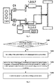
- FIG. 1 shows a structural schematic diagram of a hybrid power system of a P2.5 configuration of the prior art.
- the hybrid power system of the P2.5 configuration uses a single motor; a power battery is connected to the motor, and an engine is connected to odd axis gears of a transmission (i.e., gears 1, 3, 5, 7 in FIG. 1 ) through a first clutch C1, is connected to the motor through a second clutch C2, and is then connected to even axis gears of the transmission (i.e., gears R, 2, 4, 6 in FIG. 1 ).
- the hybrid power system of the P2.5 configuration has three torque output paths: a Disengaged Path, an ISG path and an EFAD path.
- the Disengaged Path refers to that the motor is disengaged from the engine and the even axis gears of the transmission, in a state as shown in FIG. 1 .
- the ISG path refers to that the motor is communicated with the engine through the second clutch C2, and meanwhile, the motor is disengaged from the even axis gears of the transmission, and then the engine is communicated with the odd axis gears of the transmission through the first clutch C1, as shown in FIG. 2 . In this case, a part of the torque of the engine is output to the motor, and the other part is output to a wheel through the odd axis gears of the transmission.
- the EFAD path refers to that the motor is directly connected to the even axis gears (gears R, 2, 4, 6) of the transmission to boost or charge, and the motor is disengaged from the engine. In this case, the torque of the motor is output to the wheel through the even axis gears of the transmission.
- the research on the control strategy of the hybrid power system of the P2.5 configuration in the case of abnormality of a power battery is less in the industry.
- the existing technology mainly focuses on the limp control strategy after the relay of the power battery is disengaged, but a solution that a vehicle is effectively controlled before a battery relay is disengaged to enable a motor to smoothly enter into voltage control after a battery failure is not available yet.
- the present invention discloses a control method for a hybrid electric vehicle after a battery failure.
- the control method of the present invention is applicable to the hybrid electric vehicle with the hybrid power system of the P2.5 configuration.
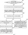
- FIG. 4 shows a schematic flow diagram of a control method for a hybrid electric vehicle after a battery failure according to an embodiment of the present invention.
- the control method for the hybrid electric vehicle after the battery failure at least may include the following steps S402 to S408.
- Step S402 after monitoring that a failure occurs in a power battery, whether the failure is a specific type of failure is judged.
- the specific type of failure is a battery failure under which a motor of a hybrid electric vehicle is capable of conducting voltage control. If so, step S404 is performed.
- Step S404 a relay of the power battery is set to be disengaged after a preset time.
- Step S406 before the relay is disengaged, the power battery, an engine, a transmission and the motor of the hybrid electric vehicle are coordinated and controlled, to enable operation states thereof to meet a preset voltage control entering condition.
- Step S408 the motor is controlled to enter into a voltage control mode.
- the control method for the hybrid electric vehicle after the battery failure after monitoring that a failure occurs in a power battery, first judges whether the failure is a specific type of failure under which a motor is capable of conducting voltage control.
- the failure of the power battery is the specific type of failure
- the power battery, an engine, a transmission and a motor of the hybrid electric vehicle are coordinated and controlled, to enable operation states thereof to meet a preset voltage control entering condition, and then the motor is controlled to enter into the voltage control mode.
- the motor can enter into voltage control and operate stably, thus avoiding problems of overtemperature of a battery, serious voltage fluctuation and the like caused by direct voltage control on the motor after a power battery failure.
- the specific type of failure mentioned in the step S402 above can also be referred to as a Voltage of Direct Current (UDC) failure, which has the following characteristics: the UDC failure is a non-serious battery failure, under which the relay of the power battery can be disengaged after a certain time (e.g., a few seconds) after the battery failure is detected, and the motor can enter into a voltage control mode.
- a Battery Management System (BMS) of the hybrid electric vehicle can be used to monitor the failure of the power battery and determine the type thereof.
- a failure signal can also be sent to remind the user.
- power battery failures are first classified in embodiments of the present invention.
- power battery failures can be classified into a UDC failure (i.e., the specific type of failure) and a non-UDC failure (i.e., a non-specific type of failure).
- the UDC failure has the features as mentioned above, specifically including slight over-heat of a battery, a mild battery insulation failure, etc.
- the non-UDC failure is generally a serious battery failure, under which the relay of the power battery may be directly disengaged, and the motor cannot conduct voltage control.
- a UDC failure set can be established, and the set may include failure codes, text description, etc. of various UDC failure types. After it is monitored that a failure occurs in the power battery (represented by failure codes, text description, etc.), the monitored failure is matched with the UDC failure set. If the monitored failure is matched with one failure type in the UDC failure set, it is determined that the monitored failure is a UDC failure.
- the relay of the power battery is set to be disengaged after the preset time, and the setting is accomplished by the BMS system.
- the preset time may be set according to actual application demands, for example, set to 5 s.
- a motor In a normal operation state of the hybrid electric vehicle, a motor generally works in a torque control mode. However, after a UDC failure of the power battery occurs, due to the lack of the power battery as an energy buffer, if the motor continues operating in the torque control mode, a bus voltage can easily exceed a threshold value, resulting in an over-voltage failure, so the motor needs to be requested to enter into motor control. However, direct voltage control of the motor can easily lead to problems such as over-temperature of the battery, serious voltage fluctuation, etc.
- step S406 in embodiments of the present invention the power battery, the engine, the transmission and the motor of the hybrid electric vehicle are coordinated and controlled, to enable operation states thereof to meet a preset voltage control entering condition, and then the motor is controlled to enter into voltage control, instead of directly enabling the motor to enter into voltage control.
- the operation states of the power battery, the engine, the transmission and the motor may include a motor mode, a motor torque, a motor rotation speed, an engine state, a charge and discharge power of the power battery, etc.
- the step S406 may specifically include the following multiple steps:
- steps (c) and (d) may be specifically implemented as: first, forbidding requesting the EFAD path (i.e., forbidding connecting the motor with the wheel through the even axis gears of the transmission, requesting to connect the ISG path, i.e., closing the second clutch C2, communicating the motor with the engine, closing the first clutch C1, selecting an appropriate odd axis gear of the transmission, and connecting the engine with the wheel, to enable the engine to meet the driver request torque.
- the motor is allowed to enter into a torque mode, and the torque of the motor is unloaded to approximately 0, such as a value within -7 Nm to 0 Nm, preferably about -5 Nm. Meanwhile, the rotation speed of the motor is adjusted to a preset rotation speed range through a speed adjusting mode.
- the operation state of the motor may further include a rotation speed of a cooling pump (such as a water pump) of the motor.
- the step S406 may further include the following steps: the cooling pump of the motor is controlled to operate at a maximum rotation speed. By controlling the rotation speed of the cooling pump of the motor to the maximum rotation speed, cooling measures for the motor can be ensured, and the temperature of the motor can be controlled, to prevent motor over-heating.
- FIG. 5 shows a schematic diagram of an energy flow direction after a motor enters into a voltage control mode according to an embodiment of the present invention. As shown in FIG.
- the motor enters into the voltage control mode, and after the relay of the power battery is disengaged, the engine drives the motor through the ISG path to generate electric power as a generator, and the electric power generated by the motor is supplied to a low-voltage (such as 12V) electric appliance system of the vehicle through a DCDC converter, so that the hybrid electric vehicle can be continuously used after the power battery failure, and the running distance of the vehicle can be prolonged.
- the DCDC converter may specifically use a Combined Inverter and DC/DC converter (CIDD) module.
- the control method may further include the following step S410: conducting voltage closed loop control on the motor by taking a current voltage of the motor (i.e., a current voltage of a high-voltage end of the motor) as a target voltage, thereby controlling the torque of the motor.
- a current voltage of the motor i.e., a current voltage of a high-voltage end of the motor
- the voltage control can be stable, with small voltage fluctuation.
- the engine may also be controlled to output an expected torque to the motor according to a preset charge power, to drive the motor to generate power to produce electric energy corresponding to the preset charge power.
- the preset charge power may be set according to actual application demands, which is not confined in the present invention.
- a certain charge power is provided for the motor through the engine to drive the motor to generate power, and then the stability of the motor voltage can be further improved.
- control method may further include the following steps S412 and S414.
- Step S412 the relay is disengaged when meeting the preset time.
- Step S414 voltage closed loop control is conducted on the motor by taking a preset voltage target value of the motor as a target voltage till the hybrid electric vehicle stops operating or the failure is repaired.
- the preset voltage target value here may be set according to a rated voltage of the power battery, for example, set at 250 V.
- the state of the relay can be monitored in real time, to judge whether the relay has been disengaged or not. If the relay is still not disengaged, return and continue implementing the step S410, and if the relay has been disengaged, implement the step S414.
- a current voltage of the motor is taken as the target voltage of the motor
- a preset voltage target value of the motor is taken as the target voltage, which may further reduce voltage fluctuation of the motor, thus making the motor operate more stably.
- step S414 voltage control on the motor may also be monitored. Specifically, while the step S414 is being implemented, a difference between the actual voltage of the motor and the preset voltage target value is monitored, and if a lasting time of the difference exceeding a preset voltage threshold exceeds a preset time threshold, the torque of the motor is reduced to 0, and the motor is controlled to exit the voltage control mode.
- Both the preset voltage threshold and the preset time threshold can be set according to actual application demands, for example, the preset voltage threshold can be set as 20 V, and the preset time threshold can be set as 2 s.
- the torque of the motor can gradually decrease (i.e., ramp) with a specific gradient to 0. When the lasting time of the difference exceeding the preset voltage threshold exceeds the preset time threshold, a failure reminding signal can be sent to remind the user.
- the closed loop control in the steps S410 and S414 may be proportion integration differentiation (PID) control.
- PID proportion integration differentiation
- the control method may further include the following step S416: by taking a difference between the driver request torque and an actual torque of the motor as an engine request torque, controlling the engine to operate according to the engine request torque to output a torque to the transmission and the motor, to enable the output torque of the engine to meet a wheel driving demand and a low-voltage system charge demand of the hybrid electric vehicle. After the motor enters into the voltage control mode, the motor generates power under the driving of the engine.
- the actual torque of the motor is a negative value
- the driver request torque may be a negative value or a positive value according to different running states of a vehicle, for example, when the vehicle slides, the driver request torque is a negative value, and when the vehicle advances normally, the driver request torque is a positive value. Therefore, by taking the difference between the driver request torque and the actual torque of the motor as an engine request torque, the actual torque of the motor can be used as an additional request compensation torque of the engine in addition to the driver request torque. By compensating the output torque of the engine according to the actual torque of the motor, after the failure occurs in the power battery, the engine is still capable of meeting the driver request and the low-voltage system power supply of the vehicle, so that the hybrid electric vehicle is still capable of keeping operating.
- the hybrid electric vehicle is still capable of operating like a conventional vehicle, the motor is capable of smoothly entering into the voltage control mode and operates stably, and while a driver is reminded of battery abnormality, the voltage control mode can also be an assistant driving mode to enable the vehicle to continue operating, thereby improving the security and the robustness of the vehicle.
- the present invention further provides a control system for a hybrid electric vehicle after a battery failure.
- the control system is also applicable to the hybrid electric vehicle with the hybrid power system of the P2.5 configuration.
- FIG. 7 shows a structural schematic diagram of a control system for a hybrid electric vehicle after a battery failure according to an embodiment of the present invention.
- the control system at least may include: a vehicle control unit 1, a motor control unit 2, a transmission control unit 3, an engine control unit 4 and a battery control unit 5.
- the battery control unit 5 (which may be a BMS) is connected to a power battery, and configured to, after monitoring that a failure occurs in the power battery, judge whether the failure is a specific type of failure or not, wherein the specific type of failure is a battery failure under which a motor of the hybrid electric vehicle is capable of conducting voltage control. If the failure is the specific type of failure, the battery control unit 5 sets that a relay of the power battery is disengaged after a preset time. The preset time may be set by the battery control unit 5 and the vehicle control unit 1 according to actual application demands, for example, set to 5 s.
- the motor control unit 2 may be a Microcontroller unit (MCU), which is connected to the motor.
- the Transmission Control Unit 3 (TCU) is connected to a transmission.
- the engine control unit 4 may be an Electronic Control Unit (ECU), which is connected to an engine.
- the Vehicle Control Unit 1 (VCU) is connected to the motor control unit 2, the transmission control unit 3, the engine control unit 4 and the battery control unit 5, respectively.
- the vehicle control unit 1, the motor control unit 2, the transmission control unit 3, the engine control unit 4 and the battery control unit 5 are configured to: before the relay is disengaged, coordinate and control the power battery, the engine, the transmission and the motor of the hybrid electric vehicle, to enable operation states thereof to meet a preset voltage control entering condition.
- the motor control unit 2 is further configured to, after the operation states of the power battery, the engine, the transmission and the motor of the hybrid electric vehicle meet the preset voltage control entering condition, control the motor to enter into a voltage control mode.
- the battery control unit 5 is further configured to: if the failure is the specific type of failure, confine a charge and discharge peak power of the power battery to a preset power limit, and send a failure signal to the vehicle control unit 1.
- the vehicle control unit 1 is further configured to: generate a corresponding control signal according to the failure signal and send the control signal to the motor control unit 2, the transmission control unit 3 and the engine control unit 4.
- the engine control unit 4 is further configured to: control the engine to be in a start state according to the control signal of the vehicle control unit 1.
- the transmission control unit 3 is further configured to: according to the control signal of the vehicle control unit 1 and a driver request torque, select a gear of the transmission with a required transmission ratio to be connected to the engine.
- the motor control unit 2 is further configured to: control the motor to be communicated with the engine according to the control signal of the vehicle control unit 1, control the torque of the motor to a preset torque range smaller than 0 and approximate to 0, and adjust the rotation speed of the motor to a preset rotation speed range.
- the vehicle control unit 1 sends an engine start request to the engine control unit 4, and the engine control unit 4 controls the engine to be in the start state according to the engine start request.
- the vehicle control unit 1 forbids requesting an EFAD path of the motor and requests an ISG path of the motor, and then the vehicle control unit 1 sends a torque control mode request and a torque control instruction to the motor control unit 2; the motor control unit 2 controls the motor to be communicated with the engine, and controls the torque of the motor to be in the preset torque range smaller than 0 and approximate to 0.
- the vehicle control unit 1 further sends a rotation speed control instruction to the motor control unit 2, and the motor control unit 2 confines the rotation speed of the motor within the preset rotation speed range according to the rotation speed control instruction.
- the vehicle control unit 1 sends an odd axis gear request to the transmission control unit 3, and the transmission control unit 3 selects an odd axis gear of the transmission with a required transmission ratio to be connected to the engine according to the odd axis gear request and the driver request torque.
- control system may further include a cooling pump control unit (not shown in FIG. 7 ).
- the cooling pump control unit is connected to the vehicle control unit 1.
- the vehicle control unit 1 is further configured to: generate a corresponding control signal according to the failure signal and send the control signal to the cooling pump control unit.
- the cooling pump control unit is further configured to: control a cooling pump of the motor to operate at a maximum rotation speed according to the control signal (specifically a cooling pump rotation speed control instruction) of the vehicle control unit 1.
- the motor control unit 2 is further configured to: after controlling the motor to enter into the voltage control mode, and before the relay is disengaged, conduct voltage closed loop control on the motor by taking a current voltage of the motor as a target voltage.
- the motor control unit 2 is further configured to: in the process of conducting voltage closed loop control on the motor by taking the current voltage of the motor as the target voltage, send a power generation request to the vehicle control unit 1 according to a preset charge power.
- the vehicle control unit 1 is further configured to: generate an engine torque distribution signal according to the power generation request and send the engine torque distribution signal to the engine control unit 4.
- the engine control unit 4 is further configured to: control the engine to output a required torque to the motor according to the engine torque distribution signal, to drive the motor to generate power to produce electric energy corresponding to the preset charge power.
- the battery control unit 5 is further configured to: after the motor control unit 2 conducts voltage closed loop control on the motor by taking the current voltage of the motor as the target voltage, disengage the relay when meeting the preset time.
- the motor control unit 2 is further configured to: after the relay is disengaged by the battery control unit 5, conduct voltage closed loop control on the motor by taking a preset voltage target value of the motor as the target voltage till the hybrid electric vehicle stops operating or the failure is repaired.
- the motor control unit 2 is further configured to: in the process of conducting voltage closed loop control on the motor by taking the preset voltage target value of the motor as the target voltage, monitor a difference between an actual voltage of the motor and the preset voltage target value; and if the lasting time of the difference exceeding a preset voltage threshold exceeds a preset time threshold, reduce the torque of the motor to 0, and control the motor to exit the voltage control mode.
- the engine control unit 4 is further configured to: after the motor control unit 2 controls the motor to enter into the voltage control mode, by taking a difference between the driver request torque and an actual torque of the motor as an engine request torque, control the engine to operate according to the engine request torque to output a torque to the transmission and the motor, to enable the output torque of the engine to meet a wheel driving demand and a low-voltage system charge demand of the hybrid electric vehicle.
- FIG. 8 shows a schematic diagram of change of operation states of components in the process from a battery failure occurring to conducting motor voltage control according to an embodiment of the present invention, and the horizontal axis in FIG. 8 represents time (in an unit of s).
- This embodiment is specifically a field test embodiment, and an initial vehicle test condition is that the vehicle runs in a pure electric mode.
- a UDC failure happens to a battery, and a failure signal is sent to the VCU.
- the VCU receives the failure signal, and an engine start request is sent to the ECU, the engine is started through a clutch, and in the start process, a clutch start loss torque is compensated by a motor torque.
- the engine is successfully started. Since the motor is connected to the even axis of the transmission, an EFAD torque output path of the motor is forbidden, and at 81.7 s, the VCU sends a motor rotation speed control mode request and a motor rotation speed request to the MCU.
- the MCU receives a request signal, changes the motor mode into a rotation speed mode, and starts to synchronize the motor rotation speed with a target rotation speed.
- the motor path is changed into the ISG path.
- the VCU sends a torque control mode request to the MCU to request controlling the motor torque to approximately -5 Nm.
- the VCU sends a voltage control mode request to the MCU.
- the MCU controls the motor to enter into voltage control, and in the voltage control, the MCU takes a current motor voltage as the target voltage, to keep the motor voltage at a current level.
- the relay of the battery is disengaged, and the voltage drop during disengagement of the relay is within a safe range.
- a high-voltage bus is separately controlled by the MCU, and is supplied with power by a single chip microcomputer, and the voltage is kept at approximately 250 V.
- the motor rotation speed changes within 1000-3500 rpm through an accelerator, and loads of 12 V are changed by turning on and turning off an air conditioner, lights, windshield wipers, etc.
- loads of 12 V are changed by turning on and turning off an air conditioner, lights, windshield wipers, etc.
- the test results of the whole vehicle show that after the failure occurs in the power battery, the motor voltage is in a good safe range before the motor enters into the voltage control mode, and the 12 V voltage is stable after the motor enters into the voltage control mode, so that the whole vehicle can operate stably.
- the present invention further provides a hybrid electric vehicle, which includes the control system for a hybrid electric vehicle after a battery failure of the forgoing any embodiment or a combination thereof.
- the embodiments of the present invention can achieve the following beneficial effects:
- the control method and system for the hybrid electric vehicle after the battery failure provided by embodiments of the present invention, after monitoring that a failure occurs in a power battery, first judge whether the failure is a specific type of failure under which a motor is capable of conducting voltage control.
- the failure of the power battery is the specific type of failure, before the relay of the power battery is disengaged, the power battery, an engine, a transmission and a motor of the hybrid electric vehicle are coordinated and controlled, to enable operation states thereof to meet a preset voltage control entering condition, and then the motor is controlled to enter into the voltage control mode.
- the motor can enter into voltage control and operate stably, thus avoiding problems of overtemperature of a battery, serious voltage fluctuation and the like caused by direct voltage control on the motor after a power battery failure.
- the difference between the driver request torque and the actual torque of the motor is taken as the engine request torque, to enable the output torque of the engine to meet the wheel driving demand and the low-voltage system charge demand of the hybrid electric vehicle, and thus after the failure occurs in the power battery, the engine is still capable of meeting the driver request and the low-voltage system charge request of the vehicle, so that the hybrid electric vehicle is still capable of continuously operating like a conventional vehicle, and the security and robustness of the vehicle are improved.
Landscapes
- Engineering & Computer Science (AREA)
- Mechanical Engineering (AREA)
- Transportation (AREA)
- Combustion & Propulsion (AREA)
- Chemical & Material Sciences (AREA)
- Power Engineering (AREA)
- Sustainable Development (AREA)
- Sustainable Energy (AREA)
- Life Sciences & Earth Sciences (AREA)
- Health & Medical Sciences (AREA)
- Biomedical Technology (AREA)
- General Health & Medical Sciences (AREA)
- Automation & Control Theory (AREA)
- Electric Propulsion And Braking For Vehicles (AREA)
- Hybrid Electric Vehicles (AREA)
Abstract
Description
- The present invention relates to the technical field of vehicles, and particularly to a control method and a control system for a hybrid electric vehicle after a battery failure, and a hybrid electric vehicle including the control system.
- Hybrid technology is a key technology to energy saving and emission reduction of vehicles. Based on the position of a motor relative to a conventional power system, single-motor hybrid power systems are classified as follows: a P0 configuration, a P1 configuration, a P2 configuration, a P2.5 configuration, a P3 configuration and a P4 configuration. At present, the industry mainly conducts research on the control of a hybrid power system on the basis of normal operation of a high-voltage battery (power battery), whereas rarely researches the control strategy for an abnormality of the high-voltage battery.
- In the prior art, a control strategy for limp of a hybrid electric vehicle after a battery relay is disengaged in case of abnormality of the high-voltage battery is proposed. The patent application with the application number
CN202010515107.5 - In view of the problems, the present invention is disclosed to provide a control method and a control system for overcoming the problem or at least partly solving the problem of a hybrid electric vehicle after a battery failure and a hybrid electric vehicle including the control system.
- One object of the present invention is to provide a control method and system for a hybrid electric vehicle after a battery failure to conduct coordination control on a power battery, a motor, a transmission and an engine before a relay of the power battery is disengaged, to enable the motor to smoothly enter into a voltage control mode and operate stably.
- A further object of the present invention is to conduct voltage control with different motor target voltages before and after the relay is disengaged, to further reduce voltage fluctuation of the motor, and enable the motor to operate stably.
- A yet further object of the present invention is to take the difference between a driver request torque and an actual torque of the motor as an engine request torque, to enable the engine to meet a driver request and a low-voltage system charge request of a vehicle, so that a hybrid electric vehicle can still continuously operate like a conventional vehicle even after a battery failure, and the security and robustness of the vehicle are improved.
- Particularly, according to one aspect of the embodiment of the present invention, the present invention provides a control method for a hybrid electric vehicle after a battery failure, including:
- after monitoring that a failure occurs in a power battery, judging whether the failure is a specific type of failure or not, wherein the specific type of failure is a battery failure under which a motor of a hybrid electric vehicle is capable of conducting voltage control;
- if so, setting a relay of the power battery to be disengaged after a preset time;
- before the relay is disengaged, coordinating and controlling the power battery, an engine, a transmission and the motor of the hybrid electric vehicle, to enable operation states thereof to meet a preset voltage control entering condition; and
- controlling the motor to enter into a voltage control mode.
- Optionally, coordinating and controlling the power battery, the engine, the transmission and the motor of the hybrid electric vehicle, to enable the operation states thereof to meet the preset voltage control entering condition, includes:
- confining a charge and discharge peak power of the power battery to a preset power limit;
- controlling the engine to be in a start state;
- according to a driver request torque, selecting a gear of the transmission with an expected transmission ratio to be connected to the engine; and
- controlling the motor to be communicated with the engine, controlling a torque of the motor to a preset torque range smaller than 0 and approximate to 0, and adjusting a rotation speed of the motor to a preset rotation speed range.
- Optionally, coordinating and controlling the power battery, the engine, the transmission and the motor of the hybrid electric vehicle, to enable the operation states thereof to meet the preset voltage control entering condition, further includes:
controlling a cooling pump of the motor to operate at a maximum rotation speed. - Optionally, after controlling the motor to enter into the voltage control mode, and before the relay is disengaged, the control method further includes:
conducting voltage closed loop control on the motor by taking a current voltage of the motor as a target voltage. - Optionally, in the process of conducting voltage closed loop control on the motor by taking the current voltage of the motor as the target voltage, the control method further includes:
according to a preset charge power, controlling the engine to output an expected torque to the motor, to drive the motor to generate power to produce electric energy corresponding to the preset charge power. - Optionally, after conducting voltage closed loop control on the motor by taking the current voltage of the motor as the target voltage, the control method further includes:
- disengaging the relay when meeting the preset time; and
- conducting voltage closed loop control on the motor by taking a preset voltage target value of the motor as the target voltage till the hybrid electric vehicle stops operating or the failure is repaired.
- Optionally, in the process of conducting voltage closed loop control on the motor by taking the preset voltage target value of the motor as the target voltage, the control method further includes:
- monitoring a difference between an actual voltage and the preset voltage target value of the motor; and
- if a lasting time of the difference exceeding a preset voltage threshold exceeds a preset time threshold, reducing the torque of the motor to 0, and controlling the motor to exit the voltage control mode.
- Optionally, the closed loop control is proportion integration differentiation (PID) control.
- Optionally, after controlling the motor to enter into the voltage control mode, the control method further includes:
by taking a difference between the driver request torque and an actual torque of the motor as an engine request torque, controlling the engine to operate according to the engine request torque to output a torque to the transmission and the motor, to enable the output torque of the engine to meet a wheel driving demand and a low-voltage system charge demand of the hybrid electric vehicle. - According to another aspect of the embodiment of the present invention, the present invention further provides a control system for a hybrid electric vehicle after a battery failure, including: a vehicle control unit, a motor control unit, a transmission control unit, an engine control unit and a battery control unit; wherein
the battery control unit is configured to: - after monitoring that a failure occurs in a power battery, judge whether the failure is a specific type of failure or not, wherein the specific type of failure is a battery failure under which a motor of a hybrid electric vehicle is capable of conducting voltage control; and
- if so, set a relay of the power battery to be disengaged after a preset time;
- the vehicle control unit, the motor control unit, the transmission control unit, the engine control unit and the battery control unit are configured to:
- before the relay is disengaged, coordinate and control the power battery, an engine, a transmission and the motor of the hybrid electric vehicle, to enable operation states thereof to meet a preset voltage control entering condition; and
- the motor control unit is further configured to:
after the operation states of the power battery, the engine, the transmission and the motor meet the preset voltage control entering condition, control the motor to enter into a voltage control mode. - Optionally, the battery control unit is further configured to: if the failure is the specific type of failure, confine a charge and discharge peak power of the power battery to a preset power limit, and send a failure signal to the vehicle control unit;
- the vehicle control unit is further configured to: generate a corresponding control signal according to the failure signal and send the control signal to the motor control unit, the transmission control unit and the engine control unit;
- the engine control unit is further configured to: control the engine to be in a start state according to the control signal of the vehicle control unit;
- the transmission control unit is further configured to: according to the control signal of the vehicle control unit and a driver request torque, select a gear of the transmission with an expected transmission ratio to be connected to the engine; and
- the motor control unit is further configured to: control the motor to be communicated with the engine according to the control signal of the vehicle control unit, control a torque of the motor to a preset torque range smaller than 0 and approximate to 0, and adjust a rotation speed of the motor to a preset rotation speed range.
- Optionally, the control system further includes a cooling pump control unit;
- the vehicle control unit is further configured to: generate a corresponding control signal according to the failure signal and send the control signal to the cooling pump control unit; and
- the cooling pump control unit is configured to: control a cooling pump of the motor to operate at a maximum rotation speed according to the control signal of the vehicle control unit.
- Optionally, the motor control unit is further configured to:
after controlling the motor to enter into the voltage control mode, and before the relay is disengaged, conduct voltage closed loop control on the motor by taking a current voltage of the motor as a target voltage. - Optionally, the motor control unit is further configured to:
- in the process of conducting voltage closed loop control on the motor by taking the current voltage of the motor as the target voltage, send a power generation request to the vehicle control unit according to a preset charge power;
- the vehicle control unit is further configured to: generate an engine torque distribution signal according to the power generation request and send the engine torque distribution signal to the engine control unit; and
- the engine control unit is further configured to: control the engine to output a required torque to the motor according to the engine torque distribution signal, to drive the motor to generate power to produce electric energy corresponding to the preset charge power.
- Optionally, the battery control unit is further configured to: after the motor control unit conducts voltage closed loop control on the motor by taking the current voltage of the motor as the target voltage, and when the preset time is met, disengage the relay; and
the motor control unit is further configured to: after the relay is disengaged by the battery control unit, conduct voltage closed loop control on the motor by taking a preset voltage target value of the motor as the target voltage till the hybrid electric vehicle stops operating or the failure is repaired. - Optionally, the motor control unit is further configured to:
- in the process of conducting voltage closed loop control on the motor by taking the preset voltage target value of the motor as the target voltage, monitor a difference between an actual voltage of the motor and the preset voltage target value; and
- if a lasting time of the difference exceeding a preset voltage threshold exceeds a preset time threshold, reduce the torque of the motor to 0, and control the motor to exit the voltage control mode.
- Optionally, the engine control unit is further configured to:
after the motor control unit controls the motor to enter into the voltage control mode, by taking a difference between the driver request torque and an actual torque of the motor as an engine request torque, control the engine to operate according to the engine request torque to output a torque to the transmission and the motor, to enable the output torque of the engine to meet a wheel driving demand and a low-voltage system charge demand of the hybrid electric vehicle. - According to yet another aspect of the embodiment of the present invention, the present invention further provides a hybrid electric vehicle, including the control system for a hybrid electric vehicle after a battery failure of any one of the embodiments.
- The control method and system for the hybrid electric vehicle after the battery failure, provided by embodiments of the present invention, after monitoring that a failure occurs in a power battery, first judge whether the failure is a specific type of failure under which a motor is capable of conducting voltage control. When the failure of the power battery is the specific type of failure, before the relay of the power battery is disengaged, the power battery, an engine, a transmission and a motor of the hybrid electric vehicle are coordinated and controlled, to enable operation states thereof to meet a preset voltage control entering condition, and then the motor is controlled to enter into the voltage control mode. In this way, the motor can enter into voltage control and operate stably, thus avoiding problems of overtemperature of a battery, serious voltage fluctuation and the like caused by direct voltage control on the motor after a power battery failure.
- Further, before and after the relay is disengaged, different motor target voltages are adopted to conduct voltage control. Specifically, before the relay is disengaged, a current voltage of the motor is taken as the target voltage of the motor, and after the relay is disengaged, a preset voltage target value of the motor is taken as the target voltage. In this way, voltage fluctuation of the motor can be further reduced, and the motor can operate more stably.
- Further, the difference between the driver request torque and the actual torque of the motor is taken as the engine request torque, to enable the output torque of the engine to meet the wheel driving demand and the low-voltage system charge demand of the hybrid electric vehicle, and thus after the failure occurs in the power battery, the engine is still capable of meeting the driver request and the low-voltage system charge request of the vehicle, so that the hybrid electric vehicle is still capable of continuously operating like a conventional vehicle, and the security and robustness of the vehicle are improved.
- The above description is only an overview of the technical solution of the present invention. To understand more clearly the technical means of the present invention, to implement in accordance with the contents of the specification, and to make the above and other purposes, features and advantages of the present invention more apparent and understandable, specific embodiments of the present invention are described below.
- According to detailed description of specific embodiments of the present invention in combination with drawings, the above and other objects, advantages and features of the present invention will be better understood by those skilled in the art.
- Hereinafter, some specific embodiments of the present invention will be described in detail in an exemplary and non-limiting manner with reference to the drawings. Identical reference signs in the drawings indicate identical or similar components or parts. It should be understood by those skilled in the art that these drawings are not necessarily drawn to scale. In drawings:
-
FIG. 1 shows a structural schematic diagram of a hybrid power system of a P2.5 configuration of the prior art; -
FIG. 2 shows a schematic diagram of an ISG torque output path of a P2.5 configuration hybrid power system; -
FIG. 3 shows a schematic diagram of an EFAD torque output path of a P2.5 configuration hybrid power system; -
FIG. 4 shows a schematic flow diagram of a control method for a hybrid electric vehicle after a battery failure according to an embodiment of the present invention; -
FIG. 5 shows a schematic diagram of an energy flow direction after a motor enters into a voltage control mode according to an embodiment of the present invention; -
FIG. 6 shows a schematic flow diagram of a control method for a hybrid electric vehicle after a battery failure according to another embodiment of the present invention; -
FIG. 7 shows a structural schematic diagram of a control system for a hybrid electric vehicle after a battery failure according to an embodiment of the present invention; and -
FIG. 8 shows a schematic diagram of change of operation states of components in the process from a battery failure occurring to conducting motor voltage control according to an embodiment of the present invention. - Exemplary embodiments of the present disclosure will be described in greater detail below with reference to the drawings. Although exemplary embodiments of the present disclosure are shown in the drawings, it should be understood that the present disclosure can be implemented in various forms and should not be limited to the embodiments elaborated herein. On the contrary, these embodiments are provided to enable a more thorough understanding of the present disclosure and to enable the complete scope of the present disclosure to be communicated to those skilled in the art.
- A hybrid power system currently has the following main configurations: a P2 configuration, a P2.5 configuration and a P3 configuration. The P2.5 configuration has the characteristics that a motor and a dual clutch transmission are integrated, the motor is connected to an even axis of the dual clutch transmission, the motor is positioned behind a clutch and before a gear, and a step gear is arranged between the transmission axis and the motor to increase the rotation speed of the motor. The hybrid power system of the P2.5 configuration has the advantages of simplified structure, simplified material, reduced weight, simple control, motor and clutch gearing thus reducing the load, high system efficiency, significant fuel saving effect, and the like.
-
FIG. 1 shows a structural schematic diagram of a hybrid power system of a P2.5 configuration of the prior art. As shown inFIG. 1 , the hybrid power system of the P2.5 configuration uses a single motor; a power battery is connected to the motor, and an engine is connected to odd axis gears of a transmission (i.e., gears 1, 3, 5, 7 inFIG. 1 ) through a first clutch C1, is connected to the motor through a second clutch C2, and is then connected to even axis gears of the transmission (i.e., gears R, 2, 4, 6 inFIG. 1 ). The hybrid power system of the P2.5 configuration has three torque output paths: a Disengaged Path, an ISG path and an EFAD path. The Disengaged Path refers to that the motor is disengaged from the engine and the even axis gears of the transmission, in a state as shown inFIG. 1 . The ISG path refers to that the motor is communicated with the engine through the second clutch C2, and meanwhile, the motor is disengaged from the even axis gears of the transmission, and then the engine is communicated with the odd axis gears of the transmission through the first clutch C1, as shown inFIG. 2 . In this case, a part of the torque of the engine is output to the motor, and the other part is output to a wheel through the odd axis gears of the transmission. The EFAD path refers to that the motor is directly connected to the even axis gears (gears R, 2, 4, 6) of the transmission to boost or charge, and the motor is disengaged from the engine. In this case, the torque of the motor is output to the wheel through the even axis gears of the transmission. - At present, the research on the control strategy of the hybrid power system of the P2.5 configuration in the case of abnormality of a power battery (can also be called high-voltage battery) is less in the industry. The existing technology mainly focuses on the limp control strategy after the relay of the power battery is disengaged, but a solution that a vehicle is effectively controlled before a battery relay is disengaged to enable a motor to smoothly enter into voltage control after a battery failure is not available yet.
- To solve the technical problems, the present invention discloses a control method for a hybrid electric vehicle after a battery failure. The control method of the present invention is applicable to the hybrid electric vehicle with the hybrid power system of the P2.5 configuration.
-
FIG. 4 shows a schematic flow diagram of a control method for a hybrid electric vehicle after a battery failure according to an embodiment of the present invention. Referring toFIG. 1 , the control method for the hybrid electric vehicle after the battery failure at least may include the following steps S402 to S408. - Step S402, after monitoring that a failure occurs in a power battery, whether the failure is a specific type of failure is judged. The specific type of failure is a battery failure under which a motor of a hybrid electric vehicle is capable of conducting voltage control. If so, step S404 is performed.
- Step S404, a relay of the power battery is set to be disengaged after a preset time.
- Step S406, before the relay is disengaged, the power battery, an engine, a transmission and the motor of the hybrid electric vehicle are coordinated and controlled, to enable operation states thereof to meet a preset voltage control entering condition.
- Step S408, the motor is controlled to enter into a voltage control mode.
- The control method for the hybrid electric vehicle after the battery failure, provided by embodiments of the present invention, after monitoring that a failure occurs in a power battery, first judges whether the failure is a specific type of failure under which a motor is capable of conducting voltage control. When the failure of the power battery is the specific type of failure, before the relay of the power battery is disengaged, the power battery, an engine, a transmission and a motor of the hybrid electric vehicle are coordinated and controlled, to enable operation states thereof to meet a preset voltage control entering condition, and then the motor is controlled to enter into the voltage control mode. In this way, the motor can enter into voltage control and operate stably, thus avoiding problems of overtemperature of a battery, serious voltage fluctuation and the like caused by direct voltage control on the motor after a power battery failure.
- The specific type of failure mentioned in the step S402 above can also be referred to as a Voltage of Direct Current (UDC) failure, which has the following characteristics: the UDC failure is a non-serious battery failure, under which the relay of the power battery can be disengaged after a certain time (e.g., a few seconds) after the battery failure is detected, and the motor can enter into a voltage control mode. In the step, a Battery Management System (BMS) of the hybrid electric vehicle can be used to monitor the failure of the power battery and determine the type thereof. In addition, after that the failure occurs in the power battery is monitored, a failure signal can also be sent to remind the user.
- Further, to conveniently judge the type of the battery failure, power battery failures are first classified in embodiments of the present invention. Generally, power battery failures can be classified into a UDC failure (i.e., the specific type of failure) and a non-UDC failure (i.e., a non-specific type of failure). The UDC failure has the features as mentioned above, specifically including slight over-heat of a battery, a mild battery insulation failure, etc. The non-UDC failure is generally a serious battery failure, under which the relay of the power battery may be directly disengaged, and the motor cannot conduct voltage control.
- In actual application, a UDC failure set can be established, and the set may include failure codes, text description, etc. of various UDC failure types. After it is monitored that a failure occurs in the power battery (represented by failure codes, text description, etc.), the monitored failure is matched with the UDC failure set. If the monitored failure is matched with one failure type in the UDC failure set, it is determined that the monitored failure is a UDC failure.
- By classifying the power battery failures, and judging the types of monitored power battery failures based on the classification, different power battery failures can be reasonably and effectively controlled, thereby improving the security of a vehicle.
- In the step S404 above, if the occurring failure of the power battery is a specific type of failure (i.e., a UDC failure), the relay of the power battery is set to be disengaged after the preset time, and the setting is accomplished by the BMS system. The preset time may be set according to actual application demands, for example, set to 5 s.
- In a normal operation state of the hybrid electric vehicle, a motor generally works in a torque control mode. However, after a UDC failure of the power battery occurs, due to the lack of the power battery as an energy buffer, if the motor continues operating in the torque control mode, a bus voltage can easily exceed a threshold value, resulting in an over-voltage failure, so the motor needs to be requested to enter into motor control. However, direct voltage control of the motor can easily lead to problems such as over-temperature of the battery, serious voltage fluctuation, etc. To enable the motor to smoothly enter into voltage control, in step S406 in embodiments of the present invention, the power battery, the engine, the transmission and the motor of the hybrid electric vehicle are coordinated and controlled, to enable operation states thereof to meet a preset voltage control entering condition, and then the motor is controlled to enter into voltage control, instead of directly enabling the motor to enter into voltage control.
- The operation states of the power battery, the engine, the transmission and the motor may include a motor mode, a motor torque, a motor rotation speed, an engine state, a charge and discharge power of the power battery, etc. In an embodiment, the step S406 may specifically include the following multiple steps:
- (a) A charge and discharge peak power of the power battery is confined to a preset power limit. The preset power limit can be set according to property parameters of the power battery, for example, set to 7 kW.
- (b) The engine is controlled to be in a start state. Specifically, if the engine has been started at the moment, the engine will be kept in the start state. If the engine is not started at the moment, the engine will be started.
- (c) According to a driver request torque, a gear of the transmission with an expected transmission ratio is selected to be connected to the engine. The driver request torque here refers to a torque requested by a wheel of the vehicle.
- (d) The motor is controlled to be communicated with the engine, the torque of the motor is controlled to a preset torque range smaller than 0 and approximate to 0, and the rotation speed of the motor is adjusted to a preset rotation speed range. The preset torque range may be set according to actual application demands, for example, set at [-7 Nm, 0 Nm]. Preferably, the torque of the motor may be controlled to/at about -5 Nm. The preset rotation speed range may be set according to actual property parameters of the motor, for example, set at 1000-5000 rpm.
- The sequence of steps (a), (b), (c) and (d) above is not definite, and the steps can be interchanged in any order or performed simultaneously.
- For the hybrid electric vehicle based on the hybrid power system of the P2.5 configuration, steps (c) and (d) may be specifically implemented as: first, forbidding requesting the EFAD path (i.e., forbidding connecting the motor with the wheel through the even axis gears of the transmission, requesting to connect the ISG path, i.e., closing the second clutch C2, communicating the motor with the engine, closing the first clutch C1, selecting an appropriate odd axis gear of the transmission, and connecting the engine with the wheel, to enable the engine to meet the driver request torque. Subsequently, the motor is allowed to enter into a torque mode, and the torque of the motor is unloaded to approximately 0, such as a value within -7 Nm to 0 Nm, preferably about -5 Nm. Meanwhile, the rotation speed of the motor is adjusted to a preset rotation speed range through a speed adjusting mode.
- In a further embodiment, the operation state of the motor may further include a rotation speed of a cooling pump (such as a water pump) of the motor. Accordingly, the step S406 may further include the following steps: the cooling pump of the motor is controlled to operate at a maximum rotation speed. By controlling the rotation speed of the cooling pump of the motor to the maximum rotation speed, cooling measures for the motor can be ensured, and the temperature of the motor can be controlled, to prevent motor over-heating.
- After the power battery, the engine, the transmission and the motor are coordinated and controlled to meet the preset voltage control entering condition, the step S408 is implemented to enable the motor to enter into the voltage control mode.
FIG. 5 shows a schematic diagram of an energy flow direction after a motor enters into a voltage control mode according to an embodiment of the present invention; As shown inFIG. 5 , the motor enters into the voltage control mode, and after the relay of the power battery is disengaged, the engine drives the motor through the ISG path to generate electric power as a generator, and the electric power generated by the motor is supplied to a low-voltage (such as 12V) electric appliance system of the vehicle through a DCDC converter, so that the hybrid electric vehicle can be continuously used after the power battery failure, and the running distance of the vehicle can be prolonged. The DCDC converter may specifically use a Combined Inverter and DC/DC converter (CIDD) module. - In another embodiment of the present invention, referring to
FIG. 6 , after the step S408, and before the relay of the power battery is disengaged, the control method may further include the following step S410: conducting voltage closed loop control on the motor by taking a current voltage of the motor (i.e., a current voltage of a high-voltage end of the motor) as a target voltage, thereby controlling the torque of the motor. Through voltage closed loop control by taking the current voltage of the motor as the target voltage before the relay is disengaged, the voltage control can be stable, with small voltage fluctuation. - In addition, to prevent the voltage of the motor from decreasing after the relay is disengaged, while the step S410 is being implemented, the engine may also be controlled to output an expected torque to the motor according to a preset charge power, to drive the motor to generate power to produce electric energy corresponding to the preset charge power. The preset charge power may be set according to actual application demands, which is not confined in the present invention. In the voltage closed loop control process of the motor before the relay is disengaged, a certain charge power is provided for the motor through the engine to drive the motor to generate power, and then the stability of the motor voltage can be further improved.
- Still referring to
FIG. 6 , in an embodiment, after the step S410, the control method may further include the following steps S412 and S414. - Step S412, the relay is disengaged when meeting the preset time.
- Step S414, voltage closed loop control is conducted on the motor by taking a preset voltage target value of the motor as a target voltage till the hybrid electric vehicle stops operating or the failure is repaired. The preset voltage target value here may be set according to a rated voltage of the power battery, for example, set at 250 V.
- In actual application, the state of the relay can be monitored in real time, to judge whether the relay has been disengaged or not. If the relay is still not disengaged, return and continue implementing the step S410, and if the relay has been disengaged, implement the step S414.
- Before and after the relay is disengaged, different motor target voltages are adopted to conduct voltage control. Specifically, before the relay is disengaged, a current voltage of the motor is taken as the target voltage of the motor, and after the relay is disengaged, a preset voltage target value of the motor is taken as the target voltage, which may further reduce voltage fluctuation of the motor, thus making the motor operate more stably.
- In a further embodiment, while the step S414 is being implemented, voltage control on the motor may also be monitored. Specifically, while the step S414 is being implemented, a difference between the actual voltage of the motor and the preset voltage target value is monitored, and if a lasting time of the difference exceeding a preset voltage threshold exceeds a preset time threshold, the torque of the motor is reduced to 0, and the motor is controlled to exit the voltage control mode. Both the preset voltage threshold and the preset time threshold can be set according to actual application demands, for example, the preset voltage threshold can be set as 20 V, and the preset time threshold can be set as 2 s. The torque of the motor can gradually decrease (i.e., ramp) with a specific gradient to 0. When the lasting time of the difference exceeding the preset voltage threshold exceeds the preset time threshold, a failure reminding signal can be sent to remind the user. By adding a specific voltage control monitoring condition, the security of the vehicle after the power battery failure can be further improved.
- Particularly, the closed loop control in the steps S410 and S414 may be proportion integration differentiation (PID) control.
- Still referring to
FIG. 6 , in an embodiment, after the step S408, the control method may further include the following step S416: by taking a difference between the driver request torque and an actual torque of the motor as an engine request torque, controlling the engine to operate according to the engine request torque to output a torque to the transmission and the motor, to enable the output torque of the engine to meet a wheel driving demand and a low-voltage system charge demand of the hybrid electric vehicle. After the motor enters into the voltage control mode, the motor generates power under the driving of the engine. At the moment, the actual torque of the motor is a negative value, and the driver request torque may be a negative value or a positive value according to different running states of a vehicle, for example, when the vehicle slides, the driver request torque is a negative value, and when the vehicle advances normally, the driver request torque is a positive value. Therefore, by taking the difference between the driver request torque and the actual torque of the motor as an engine request torque, the actual torque of the motor can be used as an additional request compensation torque of the engine in addition to the driver request torque. By compensating the output torque of the engine according to the actual torque of the motor, after the failure occurs in the power battery, the engine is still capable of meeting the driver request and the low-voltage system power supply of the vehicle, so that the hybrid electric vehicle is still capable of keeping operating. - In actual application, in the control process in which the output torque of the engine is compensated according to the actual torque of the motor, whether the actual mode of the motor is a voltage control mode or not can also be monitored; if so, output torque compensation control of the engine is continued, and if not, compensation is stopped.
- By adopting the control method of the present invention, after the failure occurs in the power battery, the hybrid electric vehicle is still capable of operating like a conventional vehicle, the motor is capable of smoothly entering into the voltage control mode and operates stably, and while a driver is reminded of battery abnormality, the voltage control mode can also be an assistant driving mode to enable the vehicle to continue operating, thereby improving the security and the robustness of the vehicle.
- Based on the same technical idea, the present invention further provides a control system for a hybrid electric vehicle after a battery failure. The control system is also applicable to the hybrid electric vehicle with the hybrid power system of the P2.5 configuration.
-
FIG. 7 shows a structural schematic diagram of a control system for a hybrid electric vehicle after a battery failure according to an embodiment of the present invention. Referring toFIG. 7 , the control system at least may include: avehicle control unit 1, amotor control unit 2, atransmission control unit 3, an engine control unit 4 and a battery control unit 5. - Functions of each component or device of the control system for the hybrid electric vehicle after the battery failure of an embodiment of the present invention and the connection relationships between the components are described.
- The battery control unit 5 (which may be a BMS) is connected to a power battery, and configured to, after monitoring that a failure occurs in the power battery, judge whether the failure is a specific type of failure or not, wherein the specific type of failure is a battery failure under which a motor of the hybrid electric vehicle is capable of conducting voltage control. If the failure is the specific type of failure, the battery control unit 5 sets that a relay of the power battery is disengaged after a preset time. The preset time may be set by the battery control unit 5 and the
vehicle control unit 1 according to actual application demands, for example, set to 5 s. - The
motor control unit 2 may be a Microcontroller unit (MCU), which is connected to the motor. The Transmission Control Unit 3 (TCU) is connected to a transmission. The engine control unit 4 may be an Electronic Control Unit (ECU), which is connected to an engine. The Vehicle Control Unit 1 (VCU) is connected to themotor control unit 2, thetransmission control unit 3, the engine control unit 4 and the battery control unit 5, respectively. Thevehicle control unit 1, themotor control unit 2, thetransmission control unit 3, the engine control unit 4 and the battery control unit 5 are configured to: before the relay is disengaged, coordinate and control the power battery, the engine, the transmission and the motor of the hybrid electric vehicle, to enable operation states thereof to meet a preset voltage control entering condition. - In addition, the
motor control unit 2 is further configured to, after the operation states of the power battery, the engine, the transmission and the motor of the hybrid electric vehicle meet the preset voltage control entering condition, control the motor to enter into a voltage control mode. - In a further embodiment, the battery control unit 5 is further configured to: if the failure is the specific type of failure, confine a charge and discharge peak power of the power battery to a preset power limit, and send a failure signal to the
vehicle control unit 1. Thevehicle control unit 1 is further configured to: generate a corresponding control signal according to the failure signal and send the control signal to themotor control unit 2, thetransmission control unit 3 and the engine control unit 4. The engine control unit 4 is further configured to: control the engine to be in a start state according to the control signal of thevehicle control unit 1. Thetransmission control unit 3 is further configured to: according to the control signal of thevehicle control unit 1 and a driver request torque, select a gear of the transmission with a required transmission ratio to be connected to the engine. Themotor control unit 2 is further configured to: control the motor to be communicated with the engine according to the control signal of thevehicle control unit 1, control the torque of the motor to a preset torque range smaller than 0 and approximate to 0, and adjust the rotation speed of the motor to a preset rotation speed range. - Specifically, the
vehicle control unit 1 sends an engine start request to the engine control unit 4, and the engine control unit 4 controls the engine to be in the start state according to the engine start request. Thevehicle control unit 1 forbids requesting an EFAD path of the motor and requests an ISG path of the motor, and then thevehicle control unit 1 sends a torque control mode request and a torque control instruction to themotor control unit 2; themotor control unit 2 controls the motor to be communicated with the engine, and controls the torque of the motor to be in the preset torque range smaller than 0 and approximate to 0. Thevehicle control unit 1 further sends a rotation speed control instruction to themotor control unit 2, and themotor control unit 2 confines the rotation speed of the motor within the preset rotation speed range according to the rotation speed control instruction. In addition, thevehicle control unit 1 sends an odd axis gear request to thetransmission control unit 3, and thetransmission control unit 3 selects an odd axis gear of the transmission with a required transmission ratio to be connected to the engine according to the odd axis gear request and the driver request torque. - In an embodiment, the control system may further include a cooling pump control unit (not shown in
FIG. 7 ). The cooling pump control unit is connected to thevehicle control unit 1. Thevehicle control unit 1 is further configured to: generate a corresponding control signal according to the failure signal and send the control signal to the cooling pump control unit. Accordingly, the cooling pump control unit is further configured to: control a cooling pump of the motor to operate at a maximum rotation speed according to the control signal (specifically a cooling pump rotation speed control instruction) of thevehicle control unit 1. - In an embodiment, the
motor control unit 2 is further configured to: after controlling the motor to enter into the voltage control mode, and before the relay is disengaged, conduct voltage closed loop control on the motor by taking a current voltage of the motor as a target voltage. - In an embodiment, the
motor control unit 2 is further configured to: in the process of conducting voltage closed loop control on the motor by taking the current voltage of the motor as the target voltage, send a power generation request to thevehicle control unit 1 according to a preset charge power. Thevehicle control unit 1 is further configured to: generate an engine torque distribution signal according to the power generation request and send the engine torque distribution signal to the engine control unit 4. The engine control unit 4 is further configured to: control the engine to output a required torque to the motor according to the engine torque distribution signal, to drive the motor to generate power to produce electric energy corresponding to the preset charge power. - In an embodiment, the battery control unit 5 is further configured to: after the
motor control unit 2 conducts voltage closed loop control on the motor by taking the current voltage of the motor as the target voltage, disengage the relay when meeting the preset time. In addition, themotor control unit 2 is further configured to: after the relay is disengaged by the battery control unit 5, conduct voltage closed loop control on the motor by taking a preset voltage target value of the motor as the target voltage till the hybrid electric vehicle stops operating or the failure is repaired. - In an embodiment, the
motor control unit 2 is further configured to: in the process of conducting voltage closed loop control on the motor by taking the preset voltage target value of the motor as the target voltage, monitor a difference between an actual voltage of the motor and the preset voltage target value; and if the lasting time of the difference exceeding a preset voltage threshold exceeds a preset time threshold, reduce the torque of the motor to 0, and control the motor to exit the voltage control mode. - In an embodiment, the engine control unit 4 is further configured to: after the
motor control unit 2 controls the motor to enter into the voltage control mode, by taking a difference between the driver request torque and an actual torque of the motor as an engine request torque, control the engine to operate according to the engine request torque to output a torque to the transmission and the motor, to enable the output torque of the engine to meet a wheel driving demand and a low-voltage system charge demand of the hybrid electric vehicle. -
FIG. 8 shows a schematic diagram of change of operation states of components in the process from a battery failure occurring to conducting motor voltage control according to an embodiment of the present invention, and the horizontal axis inFIG. 8 represents time (in an unit of s). This embodiment is specifically a field test embodiment, and an initial vehicle test condition is that the vehicle runs in a pure electric mode. Referring toFIG. 8 , at 81 s, when the vehicle speed is 20 km/h, a UDC failure happens to a battery, and a failure signal is sent to the VCU. Subsequently, the VCU receives the failure signal, and an engine start request is sent to the ECU, the engine is started through a clutch, and in the start process, a clutch start loss torque is compensated by a motor torque. At 81.5 s, the engine is successfully started. Since the motor is connected to the even axis of the transmission, an EFAD torque output path of the motor is forbidden, and at 81.7 s, the VCU sends a motor rotation speed control mode request and a motor rotation speed request to the MCU. At 81.8 s, the MCU receives a request signal, changes the motor mode into a rotation speed mode, and starts to synchronize the motor rotation speed with a target rotation speed. At 82 s, after the motor rotation speed is equal to the target rotation speed, the motor path is changed into the ISG path. At 83 s, the VCU sends a torque control mode request to the MCU to request controlling the motor torque to approximately -5 Nm. At 85 s, the VCU sends a voltage control mode request to the MCU. At 85.1 s, the MCU controls the motor to enter into voltage control, and in the voltage control, the MCU takes a current motor voltage as the target voltage, to keep the motor voltage at a current level. At 86 s, the relay of the battery is disengaged, and the voltage drop during disengagement of the relay is within a safe range. After 86 s, a high-voltage bus is separately controlled by the MCU, and is supplied with power by a single chip microcomputer, and the voltage is kept at approximately 250 V. During 86 s to 110 s, the motor rotation speed changes within 1000-3500 rpm through an accelerator, and loads of 12 V are changed by turning on and turning off an air conditioner, lights, windshield wipers, etc. The test results of the whole vehicle show that after the failure occurs in the power battery, the motor voltage is in a good safe range before the motor enters into the voltage control mode, and the 12 V voltage is stable after the motor enters into the voltage control mode, so that the whole vehicle can operate stably. - Based on the same technical idea, the present invention further provides a hybrid electric vehicle, which includes the control system for a hybrid electric vehicle after a battery failure of the forgoing any embodiment or a combination thereof.
- According to any optional embodiment or a combination of multiple optional embodiments, the embodiments of the present invention can achieve the following beneficial effects:
The control method and system for the hybrid electric vehicle after the battery failure, provided by embodiments of the present invention, after monitoring that a failure occurs in a power battery, first judge whether the failure is a specific type of failure under which a motor is capable of conducting voltage control. When the failure of the power battery is the specific type of failure, before the relay of the power battery is disengaged, the power battery, an engine, a transmission and a motor of the hybrid electric vehicle are coordinated and controlled, to enable operation states thereof to meet a preset voltage control entering condition, and then the motor is controlled to enter into the voltage control mode. In this way, the motor can enter into voltage control and operate stably, thus avoiding problems of overtemperature of a battery, serious voltage fluctuation and the like caused by direct voltage control on the motor after a power battery failure. - Further, before and after the relay is disengaged, different motor target voltages are adopted to conduct voltage control. Specifically, before the relay is disengaged, a current voltage of the motor is taken as the target voltage of the motor, and after the relay is disengaged, a preset voltage target value of the motor is taken as the target voltage. In this way, voltage fluctuation of the motor can be further reduced, and the motor can operate more stably.
- Further, the difference between the driver request torque and the actual torque of the motor is taken as the engine request torque, to enable the output torque of the engine to meet the wheel driving demand and the low-voltage system charge demand of the hybrid electric vehicle, and thus after the failure occurs in the power battery, the engine is still capable of meeting the driver request and the low-voltage system charge request of the vehicle, so that the hybrid electric vehicle is still capable of continuously operating like a conventional vehicle, and the security and robustness of the vehicle are improved.
- So far, it should be recognized by those skilled in the art that although exemplary embodiments of the present invention have been exhaustively shown and described herein, many other variations or modifications consistent with principles of the present invention can be directly identified or deduced from the present disclosure of the present invention without departing from the spirit and scope of the present invention. Therefore, the scope of the present invention should be understood and deemed as covering all these variations or modifications.
Claims (18)
- A control method for a hybrid electric vehicle after a battery failure, comprising:after monitoring that a failure occurs in a power battery, judging whether the failure is a specific type of failure or not, wherein the specific type of failure is a battery failure under which a motor of a hybrid electric vehicle is capable of conducting voltage control;if so, setting a relay of the power battery to be disengaged after a preset time;before the relay is disengaged, coordinating and controlling the power battery, an engine, a transmission and the motor of the hybrid electric vehicle, to enable operation states thereof to meet a preset voltage control entering condition; andcontrolling the motor to enter into a voltage control mode.
- The control method according to claim 1, wherein
coordinating and controlling the power battery, the engine, the transmission and the motor of the hybrid electric vehicle, to enable the operation states thereof to meet the preset voltage control entering condition, comprises:confining a charge and discharge peak power of the power battery to a preset power limit;controlling the engine to be in a start state;according to a driver request torque, selecting a gear of the transmission with an expected transmission ratio to be connected to the engine; andcontrolling the motor to be communicated with the engine, controlling a torque of the motor to a preset torque range smaller than 0 and approximate to 0, and adjusting a rotation speed of the motor to a preset rotation speed range. - The control method according to claim 2, wherein coordinating and controlling the power battery, the engine, the transmission and the motor of the hybrid electric vehicle, to enable the operation states thereof to meet the preset voltage control entering condition, further comprises:
controlling a cooling pump of the motor to operate at a maximum rotation speed. - The control method according to claim 1, wherein after controlling the motor to enter into the voltage control mode, and before the relay is disengaged, the control method further comprises:
conducting voltage closed loop control on the motor by taking a current voltage of the motor as a target voltage. - The control method according to claim 4, wherein in the process of conducting voltage closed loop control on the motor by taking the current voltage of the motor as the target voltage, the control method further comprises:
according to a preset charge power, controlling the engine to output an expected torque to the motor, to drive the motor to generate power to produce electric energy corresponding to the preset charge power. - The control method according to claim 4, wherein after conducting voltage closed loop control on the motor by taking the current voltage of the motor as the target voltage, the control method further comprises:disengaging the relay when meeting the preset time; andconducting voltage closed loop control on the motor by taking a preset voltage target value of the motor as the target voltage till the hybrid electric vehicle stops operating or the failure is repaired.
- The control method according to claim 6, wherein in the process of conducting voltage closed loop control on the motor by taking the preset voltage target value of the motor as the target voltage, the control method further comprises:monitoring a difference between an actual voltage and the preset voltage target value of the motor; andif a lasting time of the difference exceeding a preset voltage threshold exceeds a preset time threshold, reducing a torque of the motor to 0, and controlling the motor to exit the voltage control mode.
- The control method according to any one of claims 4-7, wherein the closed loop control is proportion integration differentiation (PID) control.
- The control method according to claim 2, wherein after controlling the motor to enter into the voltage control mode, the control method further comprises:
by taking a difference between the driver request torque and an actual torque of the motor as an engine request torque, controlling the engine to operate according to the engine request torque to output a torque to the transmission and the motor, to enable the output torque of the engine to meet a wheel driving demand and a low-voltage system charge demand of the hybrid electric vehicle. - A control system for a hybrid electric vehicle after a battery failure, comprising: a vehicle control unit, a motor control unit, a transmission control unit, an engine control unit and a battery control unit, wherein
the battery control unit is configured to:after monitoring that a failure occurs in a power battery, judge whether the failure is a specific type of failure or not, wherein the specific type of failure is a battery failure under which a motor of a hybrid electric vehicle is capable of conducting voltage control; andif so, set a relay of the power battery to be disengaged after a preset time;the vehicle control unit, the motor control unit, the transmission control unit, the engine control unit and the battery control unit are configured to:before the relay is disengaged, coordinate and control the power battery, an engine, a transmission and the motor of the hybrid electric vehicle, to enable operation states thereof to meet a preset voltage control entering condition; andthe motor control unit is further configured to:
after the operation states of the power battery, the engine, the transmission and the motor meet the preset voltage control entering condition, control the motor to enter into a voltage control mode. - The control system according to claim 10, whereinthe battery control unit is further configured to: if the failure is the specific type of failure, confine a charge and discharge peak power of the power battery to a preset power limit, and send a failure signal to the vehicle control unit;the vehicle control unit is further configured to: generate a corresponding control signal according to the failure signal and send the control signal to the motor control unit, the transmission control unit and the engine control unit;the engine control unit is further configured to: control the engine to be in a start state according to the control signal of the vehicle control unit;the transmission control unit is further configured to: according to the control signal of the vehicle control unit and a driver request torque, select a gear of the transmission with an expected transmission ratio to be connected to the engine; andthe motor control unit is further configured to: control the motor to be communicated with the engine according to the control signal of the vehicle control unit, control a torque of the motor to a preset torque range smaller than 0 and approximate to 0, and adjust a rotation speed of the motor to a preset rotation speed range.
- The control system according to claim 11, wherein the control system further comprises a cooling pump control unit;the vehicle control unit is further configured to: generate a corresponding control signal according to the failure signal and send the control signal to the cooling pump control unit; andthe cooling pump control unit is configured to: control a cooling pump of the motor to operate at a maximum rotation speed according to the control signal of the vehicle control unit.
- The control system according to claim 10, wherein the motor control unit is further configured to:
after controlling the motor to enter into the voltage control mode, and before the relay is disengaged, conduct voltage closed loop control on the motor by taking a current voltage of the motor as a target voltage. - The control system according to claim 13, wherein the motor control unit is further configured to:in the process of conducting voltage closed loop control on the motor by taking the current voltage of the motor as the target voltage, send a power generation request to the vehicle control unit according to a preset charge power;the vehicle control unit is further configured to: generate an engine torque distribution signal according to the power generation request and send the engine torque distribution signal to the engine control unit; andthe engine control unit is further configured to: control the engine to output a required torque to the motor according to the engine torque distribution signal, to drive the motor to generate power to produce electric energy corresponding to the preset charge power.
- The control system according to claim 13, wherein the battery control unit is further configured to: after the motor control unit conducts voltage closed loop control on the motor by taking the current voltage of the motor as the target voltage, and when the preset time is met, disengage the relay; and
the motor control unit is further configured to: after the relay is disengaged by the battery control unit, conduct voltage closed loop control on the motor by taking a preset voltage target value of the motor as the target voltage till the hybrid electric vehicle stops operating or the failure is repaired. - The control system according to claim 15, wherein the motor control unit is further configured to:in the process of conducting voltage closed loop control on the motor by taking the preset voltage target value of the motor as the target voltage, monitor a difference between an actual voltage of the motor and the preset voltage target value; andif a lasting time of the difference exceeding a preset voltage threshold exceeds a preset time threshold, reduce a torque of the motor to 0, and control the motor to exit the voltage control mode.
- The control system according to claim 11, wherein the engine control unit is further configured to:
after the motor control unit controls the motor to enter into the voltage control mode, by taking a difference between the driver request torque and an actual torque of the motor as an engine request torque, control the engine to operate according to the engine request torque to output a torque to the transmission and the motor, to enable the output torque of the engine to meet a wheel driving demand and a low-voltage system charge demand of the hybrid electric vehicle. - A hybrid electric vehicle, comprising the control system for a hybrid electric vehicle after a battery failure of any one of claims 10-17.
Applications Claiming Priority (1)
| Application Number | Priority Date | Filing Date | Title |
|---|---|---|---|
| PCT/CN2020/126433 WO2022094786A1 (en) | 2020-11-04 | 2020-11-04 | Hybrid vehicle and control method and system after hybrid vehicle battery failure |
Publications (3)
| Publication Number | Publication Date |
|---|---|
| EP4032737A1 true EP4032737A1 (en) | 2022-07-27 |
| EP4032737A4 EP4032737A4 (en) | 2022-11-30 |
| EP4032737B1 EP4032737B1 (en) | 2023-10-04 |
Family
ID=80824503
Family Applications (1)
| Application Number | Title | Priority Date | Filing Date |
|---|---|---|---|
| EP20955472.4A Active EP4032737B1 (en) | 2020-11-04 | 2020-11-04 | Hybrid vehicle and control method and system after hybrid vehicle battery failure |
Country Status (3)
| Country | Link |
|---|---|
| EP (1) | EP4032737B1 (en) |
| CN (1) | CN114269617B (en) |
| WO (1) | WO2022094786A1 (en) |
Families Citing this family (14)
| Publication number | Priority date | Publication date | Assignee | Title |
|---|---|---|---|---|
| US20250065863A1 (en) * | 2021-12-23 | 2025-02-27 | Cummins Inc. | Control system for hybrid electric vehicle |
| CN114889583A (en) * | 2022-05-17 | 2022-08-12 | 岚图汽车科技有限公司 | Method and device for controlling driving motor of hybrid electric vehicle |
| CN117341669A (en) * | 2022-06-28 | 2024-01-05 | 长城汽车股份有限公司 | Vehicle and hybrid system control method and device, storage medium |
| CN115195698B (en) * | 2022-06-29 | 2025-04-01 | 中国第一汽车股份有限公司 | Engine starting method |
| CN115416489B (en) * | 2022-08-22 | 2025-07-01 | 东风汽车集团股份有限公司 | Fault handling method, device and new energy vehicle |
| CN115327465A (en) * | 2022-08-29 | 2022-11-11 | 广汽埃安新能源汽车有限公司 | Monitoring method and device of three power test system |
| CN115402106B (en) * | 2022-08-30 | 2023-09-26 | 小米汽车科技有限公司 | Voltage control method, device, vehicle and storage medium for vehicle |
| CN115571109B (en) * | 2022-10-24 | 2026-04-14 | 深蓝汽车科技有限公司 | Hybrid boosting control system and method and vehicle |
| CN115923771B (en) * | 2023-01-02 | 2025-07-22 | 重庆长安汽车股份有限公司 | Engine start control method under battery fault in running of hybrid vehicle and vehicle |
| CN115923519B (en) * | 2023-01-02 | 2025-05-09 | 重庆长安汽车股份有限公司 | Hybrid vehicle boost/lower module overcurrent protection method, system, vehicle and storage medium |
| CN117698509B (en) * | 2024-02-02 | 2024-07-12 | 宁德时代新能源科技股份有限公司 | Method and apparatus for controlling battery |
| CN119821355B (en) * | 2025-02-24 | 2025-11-21 | 长城汽车股份有限公司 | Vehicle control method and device, vehicle and storage medium |
| CN119773728A (en) * | 2025-03-11 | 2025-04-08 | 宁德时代新能源科技股份有限公司 | Vehicle control method, vehicle control device, multi-power vehicle and storage medium |
| CN119928820A (en) * | 2025-03-21 | 2025-05-06 | 长城汽车股份有限公司 | Vehicle control method, device, vehicle and computer readable storage medium |
Family Cites Families (16)
| Publication number | Priority date | Publication date | Assignee | Title |
|---|---|---|---|---|
| KR100921061B1 (en) * | 2008-03-27 | 2009-10-08 | 현대자동차주식회사 | How to protect your battery in a hybrid vehicle |
| KR101144033B1 (en) * | 2009-12-04 | 2012-05-23 | 현대자동차주식회사 | Method for controlling motor control system for hybrid vehicle |
| JP2013133041A (en) * | 2011-12-27 | 2013-07-08 | Toyota Motor Corp | Hybrid vehicle and method of controlling the same |
| US9481354B2 (en) * | 2014-05-08 | 2016-11-01 | Hyundai Motor Company | Emergency operation method of hybrid vehicle |
| KR101684099B1 (en) * | 2015-04-15 | 2016-12-20 | 현대자동차주식회사 | Fail safe apparatus and method for eco-friendly vehicle |
| KR102383451B1 (en) * | 2016-12-16 | 2022-04-06 | 현대자동차주식회사 | Apparatus and Method for controlling power generation in a vehicle |
| CN107487321B (en) * | 2017-06-19 | 2020-01-17 | 宝沃汽车(中国)有限公司 | Clutch control method and device of hybrid electric vehicle |
| CN108528440B (en) * | 2018-03-27 | 2020-05-19 | 吉利汽车研究院(宁波)有限公司 | High-voltage power supply control method for hybrid vehicle |
| CN108859766B (en) * | 2018-06-04 | 2021-03-16 | 武汉理工大学 | Four-wheel hub motor hybrid electric vehicle fault coordination control method |
| CN108819937B (en) * | 2018-07-04 | 2020-04-07 | 重庆长安汽车股份有限公司 | New energy automobile limping mode control method and system |
| CN111619350A (en) * | 2019-02-27 | 2020-09-04 | 北京宝沃汽车有限公司 | Vehicle control method, vehicle control system and vehicle |
| CN110606074B (en) * | 2019-09-26 | 2020-09-22 | 中国第一汽车股份有限公司 | Limping control method of 48V hybrid vehicle |
| CN110782633A (en) * | 2019-10-31 | 2020-02-11 | 重庆长安新能源汽车科技有限公司 | New energy automobile power battery thermal runaway alarm system and method |
| CN110877607B (en) * | 2019-11-26 | 2021-04-06 | 重庆长安汽车股份有限公司 | Self-power-generation limping system and method for hybrid electric vehicle |
| CN111546894A (en) * | 2020-05-21 | 2020-08-18 | 新石器慧通(北京)科技有限公司 | Vehicle abnormal power-off control method and system and vehicle |
| CN111717029B (en) * | 2020-06-08 | 2022-03-22 | 北京汽车股份有限公司 | Limp-home mode low-voltage load power supply control method and system and hybrid electric vehicle |
-
2020
- 2020-11-04 EP EP20955472.4A patent/EP4032737B1/en active Active
- 2020-11-04 WO PCT/CN2020/126433 patent/WO2022094786A1/en not_active Ceased
- 2020-11-04 CN CN202080051345.3A patent/CN114269617B/en active Active
Also Published As
| Publication number | Publication date |
|---|---|
| WO2022094786A1 (en) | 2022-05-12 |
| CN114269617B (en) | 2023-12-05 |
| EP4032737A4 (en) | 2022-11-30 |
| EP4032737B1 (en) | 2023-10-04 |
| CN114269617A (en) | 2022-04-01 |
Similar Documents
| Publication | Publication Date | Title |
|---|---|---|
| EP4032737B1 (en) | Hybrid vehicle and control method and system after hybrid vehicle battery failure | |
| US11351975B2 (en) | Hybrid-electric vehicle plug-out mode energy management | |
| CN102616148B (en) | Range extended electric vehicle control system and method | |
| US7317985B2 (en) | Motor vehicle and control method of motor vehicle | |
| EP2404801B1 (en) | Charge/discharge control system for hybrid vehicle, and control method therefor | |
| US9296289B2 (en) | Hybrid vehicle and control method of hybrid vehicle | |
| US9631547B2 (en) | PHEV heating modes to provide cabin comfort | |
| US10160307B2 (en) | System and method for controlling motor temperature for green car | |
| US10124651B2 (en) | Systems and methods for controlling electrically powered heating devices within electrified vehicles | |
| US8527114B2 (en) | Silent key start climate control demand | |
| CN103775221A (en) | System and method for controlling a vehicle having an electric heater | |
| US20160212885A1 (en) | Hybrid vehicle | |
| US20130144515A1 (en) | Apparatus for controlling engine warming-up | |
| US20230053169A1 (en) | Blower motor operation for an electrified vehicle | |
| KR20180022127A (en) | Method and device for controlling output of low voltage DC-DC converter in environmentally friendly vehicle | |
| KR101765643B1 (en) | Method and device for controlling state of charge of battery for cruise control of hybrid vehicle | |
| WO2022217388A1 (en) | Dual-electric motor hybrid electric vehicle, and method and system for handling battery faults thereof | |
| EP4159518B1 (en) | Dcdc output voltage control method and control system for hybrid vehicle | |
| JP2009160978A (en) | Internal combustion engine control device | |
| KR101198808B1 (en) | Method for controling engine idle of hybrid electric vehicle | |
| US12110006B2 (en) | System and method for controlling limp-home reverse traveling of hybrid electric vehicle | |
| KR102598417B1 (en) | Controlling method for heating of hybrid vehicle | |
| US11916208B2 (en) | Electrified vehicle with cabin pre-cooling strategy for managing battery and cabin cooling loads | |
| Jing et al. | Research on voltage control of P2. 5 hybrid system | |
| Tashiro | Power Management of a Hybrid Electric Vehicle During Warm-up Period Considering Energy Consumption of Cabin Heat Components |
Legal Events
| Date | Code | Title | Description |
|---|---|---|---|
| STAA | Information on the status of an ep patent application or granted ep patent |
Free format text: STATUS: UNKNOWN |
|
| STAA | Information on the status of an ep patent application or granted ep patent |
Free format text: STATUS: THE INTERNATIONAL PUBLICATION HAS BEEN MADE |
|
| PUAI | Public reference made under article 153(3) epc to a published international application that has entered the european phase |
Free format text: ORIGINAL CODE: 0009012 |
|
| STAA | Information on the status of an ep patent application or granted ep patent |
Free format text: STATUS: REQUEST FOR EXAMINATION WAS MADE |
|
| 17P | Request for examination filed |
Effective date: 20220407 |
|
| AK | Designated contracting states |
Kind code of ref document: A1 Designated state(s): AL AT BE BG CH CY CZ DE DK EE ES FI FR GB GR HR HU IE IS IT LI LT LU LV MC MK MT NL NO PL PT RO RS SE SI SK SM TR |
|
| STAA | Information on the status of an ep patent application or granted ep patent |
Free format text: STATUS: EXAMINATION IS IN PROGRESS |
|
| A4 | Supplementary search report drawn up and despatched |
Effective date: 20221102 |
|
| RIC1 | Information provided on ipc code assigned before grant |
Ipc: B60L 50/61 20190101ALI20221026BHEP Ipc: B60L 50/16 20190101ALI20221026BHEP Ipc: B60L 15/20 20060101ALI20221026BHEP Ipc: B60L 3/00 20190101AFI20221026BHEP |
|
| 17Q | First examination report despatched |
Effective date: 20221114 |
|
| RIC1 | Information provided on ipc code assigned before grant |
Ipc: B60L 50/61 20190101ALI20230220BHEP Ipc: B60L 50/16 20190101ALI20230220BHEP Ipc: B60L 15/20 20060101ALI20230220BHEP Ipc: B60L 3/00 20060101AFI20230220BHEP |
|
| GRAP | Despatch of communication of intention to grant a patent |
Free format text: ORIGINAL CODE: EPIDOSNIGR1 |
|
| STAA | Information on the status of an ep patent application or granted ep patent |
Free format text: STATUS: GRANT OF PATENT IS INTENDED |
|
| DAV | Request for validation of the european patent (deleted) | ||
| DAX | Request for extension of the european patent (deleted) | ||
| INTG | Intention to grant announced |
Effective date: 20230426 |
|
| GRAS | Grant fee paid |
Free format text: ORIGINAL CODE: EPIDOSNIGR3 |
|
| GRAA | (expected) grant |
Free format text: ORIGINAL CODE: 0009210 |
|
| STAA | Information on the status of an ep patent application or granted ep patent |
Free format text: STATUS: THE PATENT HAS BEEN GRANTED |
|
| AK | Designated contracting states |
Kind code of ref document: B1 Designated state(s): AL AT BE BG CH CY CZ DE DK EE ES FI FR GB GR HR HU IE IS IT LI LT LU LV MC MK MT NL NO PL PT RO RS SE SI SK SM TR |
|
| REG | Reference to a national code |
Ref country code: GB Ref legal event code: FG4D |
|
| REG | Reference to a national code |
Ref country code: CH Ref legal event code: EP |
|
| REG | Reference to a national code |
Ref country code: IE Ref legal event code: FG4D |
|
| REG | Reference to a national code |
Ref country code: DE Ref legal event code: R096 Ref document number: 602020018857 Country of ref document: DE |
|
| REG | Reference to a national code |
Ref country code: NL Ref legal event code: FP |
|
| REG | Reference to a national code |
Ref country code: LT Ref legal event code: MG9D |
|
| REG | Reference to a national code |
Ref country code: AT Ref legal event code: MK05 Ref document number: 1617436 Country of ref document: AT Kind code of ref document: T Effective date: 20231004 |
|
| PG25 | Lapsed in a contracting state [announced via postgrant information from national office to epo] |
Ref country code: GR Free format text: LAPSE BECAUSE OF FAILURE TO SUBMIT A TRANSLATION OF THE DESCRIPTION OR TO PAY THE FEE WITHIN THE PRESCRIBED TIME-LIMIT Effective date: 20240105 |
|
| PG25 | Lapsed in a contracting state [announced via postgrant information from national office to epo] |
Ref country code: IS Free format text: LAPSE BECAUSE OF FAILURE TO SUBMIT A TRANSLATION OF THE DESCRIPTION OR TO PAY THE FEE WITHIN THE PRESCRIBED TIME-LIMIT Effective date: 20240204 |
|
| PG25 | Lapsed in a contracting state [announced via postgrant information from national office to epo] |
Ref country code: LT Free format text: LAPSE BECAUSE OF FAILURE TO SUBMIT A TRANSLATION OF THE DESCRIPTION OR TO PAY THE FEE WITHIN THE PRESCRIBED TIME-LIMIT Effective date: 20231004 |
|
| PG25 | Lapsed in a contracting state [announced via postgrant information from national office to epo] |
Ref country code: AT Free format text: LAPSE BECAUSE OF FAILURE TO SUBMIT A TRANSLATION OF THE DESCRIPTION OR TO PAY THE FEE WITHIN THE PRESCRIBED TIME-LIMIT Effective date: 20231004 |
|
| PG25 | Lapsed in a contracting state [announced via postgrant information from national office to epo] |
Ref country code: ES Free format text: LAPSE BECAUSE OF FAILURE TO SUBMIT A TRANSLATION OF THE DESCRIPTION OR TO PAY THE FEE WITHIN THE PRESCRIBED TIME-LIMIT Effective date: 20231004 |
|
| PG25 | Lapsed in a contracting state [announced via postgrant information from national office to epo] |
Ref country code: LT Free format text: LAPSE BECAUSE OF FAILURE TO SUBMIT A TRANSLATION OF THE DESCRIPTION OR TO PAY THE FEE WITHIN THE PRESCRIBED TIME-LIMIT Effective date: 20231004 Ref country code: IS Free format text: LAPSE BECAUSE OF FAILURE TO SUBMIT A TRANSLATION OF THE DESCRIPTION OR TO PAY THE FEE WITHIN THE PRESCRIBED TIME-LIMIT Effective date: 20240204 Ref country code: GR Free format text: LAPSE BECAUSE OF FAILURE TO SUBMIT A TRANSLATION OF THE DESCRIPTION OR TO PAY THE FEE WITHIN THE PRESCRIBED TIME-LIMIT Effective date: 20240105 Ref country code: ES Free format text: LAPSE BECAUSE OF FAILURE TO SUBMIT A TRANSLATION OF THE DESCRIPTION OR TO PAY THE FEE WITHIN THE PRESCRIBED TIME-LIMIT Effective date: 20231004 Ref country code: BG Free format text: LAPSE BECAUSE OF FAILURE TO SUBMIT A TRANSLATION OF THE DESCRIPTION OR TO PAY THE FEE WITHIN THE PRESCRIBED TIME-LIMIT Effective date: 20240104 Ref country code: AT Free format text: LAPSE BECAUSE OF FAILURE TO SUBMIT A TRANSLATION OF THE DESCRIPTION OR TO PAY THE FEE WITHIN THE PRESCRIBED TIME-LIMIT Effective date: 20231004 Ref country code: PT Free format text: LAPSE BECAUSE OF FAILURE TO SUBMIT A TRANSLATION OF THE DESCRIPTION OR TO PAY THE FEE WITHIN THE PRESCRIBED TIME-LIMIT Effective date: 20240205 |
|
| PG25 | Lapsed in a contracting state [announced via postgrant information from national office to epo] |
Ref country code: SE Free format text: LAPSE BECAUSE OF FAILURE TO SUBMIT A TRANSLATION OF THE DESCRIPTION OR TO PAY THE FEE WITHIN THE PRESCRIBED TIME-LIMIT Effective date: 20231004 Ref country code: RS Free format text: LAPSE BECAUSE OF FAILURE TO SUBMIT A TRANSLATION OF THE DESCRIPTION OR TO PAY THE FEE WITHIN THE PRESCRIBED TIME-LIMIT Effective date: 20231004 Ref country code: PL Free format text: LAPSE BECAUSE OF FAILURE TO SUBMIT A TRANSLATION OF THE DESCRIPTION OR TO PAY THE FEE WITHIN THE PRESCRIBED TIME-LIMIT Effective date: 20231004 Ref country code: NO Free format text: LAPSE BECAUSE OF FAILURE TO SUBMIT A TRANSLATION OF THE DESCRIPTION OR TO PAY THE FEE WITHIN THE PRESCRIBED TIME-LIMIT Effective date: 20240104 Ref country code: LV Free format text: LAPSE BECAUSE OF FAILURE TO SUBMIT A TRANSLATION OF THE DESCRIPTION OR TO PAY THE FEE WITHIN THE PRESCRIBED TIME-LIMIT Effective date: 20231004 Ref country code: HR Free format text: LAPSE BECAUSE OF FAILURE TO SUBMIT A TRANSLATION OF THE DESCRIPTION OR TO PAY THE FEE WITHIN THE PRESCRIBED TIME-LIMIT Effective date: 20231004 |
|
| REG | Reference to a national code |
Ref country code: CH Ref legal event code: PL |
|
| REG | Reference to a national code |
Ref country code: DE Ref legal event code: R097 Ref document number: 602020018857 Country of ref document: DE |
|
| PG25 | Lapsed in a contracting state [announced via postgrant information from national office to epo] |
Ref country code: DK Free format text: LAPSE BECAUSE OF FAILURE TO SUBMIT A TRANSLATION OF THE DESCRIPTION OR TO PAY THE FEE WITHIN THE PRESCRIBED TIME-LIMIT Effective date: 20231004 |
|
| PG25 | Lapsed in a contracting state [announced via postgrant information from national office to epo] |
Ref country code: LU Free format text: LAPSE BECAUSE OF NON-PAYMENT OF DUE FEES Effective date: 20231104 |
|
| PG25 | Lapsed in a contracting state [announced via postgrant information from national office to epo] |
Ref country code: CH Free format text: LAPSE BECAUSE OF NON-PAYMENT OF DUE FEES Effective date: 20231130 |
|
| PG25 | Lapsed in a contracting state [announced via postgrant information from national office to epo] |
Ref country code: CZ Free format text: LAPSE BECAUSE OF FAILURE TO SUBMIT A TRANSLATION OF THE DESCRIPTION OR TO PAY THE FEE WITHIN THE PRESCRIBED TIME-LIMIT Effective date: 20231004 |
|
| PG25 | Lapsed in a contracting state [announced via postgrant information from national office to epo] |
Ref country code: SK Free format text: LAPSE BECAUSE OF FAILURE TO SUBMIT A TRANSLATION OF THE DESCRIPTION OR TO PAY THE FEE WITHIN THE PRESCRIBED TIME-LIMIT Effective date: 20231004 |
|
| PG25 | Lapsed in a contracting state [announced via postgrant information from national office to epo] |
Ref country code: SM Free format text: LAPSE BECAUSE OF FAILURE TO SUBMIT A TRANSLATION OF THE DESCRIPTION OR TO PAY THE FEE WITHIN THE PRESCRIBED TIME-LIMIT Effective date: 20231004 Ref country code: SK Free format text: LAPSE BECAUSE OF FAILURE TO SUBMIT A TRANSLATION OF THE DESCRIPTION OR TO PAY THE FEE WITHIN THE PRESCRIBED TIME-LIMIT Effective date: 20231004 Ref country code: RO Free format text: LAPSE BECAUSE OF FAILURE TO SUBMIT A TRANSLATION OF THE DESCRIPTION OR TO PAY THE FEE WITHIN THE PRESCRIBED TIME-LIMIT Effective date: 20231004 Ref country code: LU Free format text: LAPSE BECAUSE OF NON-PAYMENT OF DUE FEES Effective date: 20231104 Ref country code: IT Free format text: LAPSE BECAUSE OF FAILURE TO SUBMIT A TRANSLATION OF THE DESCRIPTION OR TO PAY THE FEE WITHIN THE PRESCRIBED TIME-LIMIT Effective date: 20231004 Ref country code: EE Free format text: LAPSE BECAUSE OF FAILURE TO SUBMIT A TRANSLATION OF THE DESCRIPTION OR TO PAY THE FEE WITHIN THE PRESCRIBED TIME-LIMIT Effective date: 20231004 Ref country code: DK Free format text: LAPSE BECAUSE OF FAILURE TO SUBMIT A TRANSLATION OF THE DESCRIPTION OR TO PAY THE FEE WITHIN THE PRESCRIBED TIME-LIMIT Effective date: 20231004 Ref country code: CZ Free format text: LAPSE BECAUSE OF FAILURE TO SUBMIT A TRANSLATION OF THE DESCRIPTION OR TO PAY THE FEE WITHIN THE PRESCRIBED TIME-LIMIT Effective date: 20231004 Ref country code: CH Free format text: LAPSE BECAUSE OF NON-PAYMENT OF DUE FEES Effective date: 20231130 |
|
| REG | Reference to a national code |
Ref country code: BE Ref legal event code: MM Effective date: 20231130 |
|
| PLBE | No opposition filed within time limit |
Free format text: ORIGINAL CODE: 0009261 |
|
| STAA | Information on the status of an ep patent application or granted ep patent |
Free format text: STATUS: NO OPPOSITION FILED WITHIN TIME LIMIT |
|
| PG25 | Lapsed in a contracting state [announced via postgrant information from national office to epo] |
Ref country code: MC Free format text: LAPSE BECAUSE OF FAILURE TO SUBMIT A TRANSLATION OF THE DESCRIPTION OR TO PAY THE FEE WITHIN THE PRESCRIBED TIME-LIMIT Effective date: 20231004 |
|
| PG25 | Lapsed in a contracting state [announced via postgrant information from national office to epo] |
Ref country code: MC Free format text: LAPSE BECAUSE OF FAILURE TO SUBMIT A TRANSLATION OF THE DESCRIPTION OR TO PAY THE FEE WITHIN THE PRESCRIBED TIME-LIMIT Effective date: 20231004 |
|
| 26N | No opposition filed |
Effective date: 20240705 |
|
| REG | Reference to a national code |
Ref country code: IE Ref legal event code: MM4A |
|
| PG25 | Lapsed in a contracting state [announced via postgrant information from national office to epo] |
Ref country code: IE Free format text: LAPSE BECAUSE OF NON-PAYMENT OF DUE FEES Effective date: 20231104 |
|
| PG25 | Lapsed in a contracting state [announced via postgrant information from national office to epo] |
Ref country code: BE Free format text: LAPSE BECAUSE OF NON-PAYMENT OF DUE FEES Effective date: 20231130 |
|
| PG25 | Lapsed in a contracting state [announced via postgrant information from national office to epo] |
Ref country code: SI Free format text: LAPSE BECAUSE OF FAILURE TO SUBMIT A TRANSLATION OF THE DESCRIPTION OR TO PAY THE FEE WITHIN THE PRESCRIBED TIME-LIMIT Effective date: 20231004 |
|
| PG25 | Lapsed in a contracting state [announced via postgrant information from national office to epo] |
Ref country code: SI Free format text: LAPSE BECAUSE OF FAILURE TO SUBMIT A TRANSLATION OF THE DESCRIPTION OR TO PAY THE FEE WITHIN THE PRESCRIBED TIME-LIMIT Effective date: 20231004 Ref country code: IE Free format text: LAPSE BECAUSE OF NON-PAYMENT OF DUE FEES Effective date: 20231104 Ref country code: BE Free format text: LAPSE BECAUSE OF NON-PAYMENT OF DUE FEES Effective date: 20231130 |
|
| PG25 | Lapsed in a contracting state [announced via postgrant information from national office to epo] |
Ref country code: FI Free format text: LAPSE BECAUSE OF FAILURE TO SUBMIT A TRANSLATION OF THE DESCRIPTION OR TO PAY THE FEE WITHIN THE PRESCRIBED TIME-LIMIT Effective date: 20231004 |
|
| GBPC | Gb: european patent ceased through non-payment of renewal fee |
Effective date: 20241104 |
|
| PG25 | Lapsed in a contracting state [announced via postgrant information from national office to epo] |
Ref country code: CY Free format text: LAPSE BECAUSE OF FAILURE TO SUBMIT A TRANSLATION OF THE DESCRIPTION OR TO PAY THE FEE WITHIN THE PRESCRIBED TIME-LIMIT; INVALID AB INITIO Effective date: 20201104 |
|
| PG25 | Lapsed in a contracting state [announced via postgrant information from national office to epo] |
Ref country code: HU Free format text: LAPSE BECAUSE OF FAILURE TO SUBMIT A TRANSLATION OF THE DESCRIPTION OR TO PAY THE FEE WITHIN THE PRESCRIBED TIME-LIMIT; INVALID AB INITIO Effective date: 20201104 |
|
| PG25 | Lapsed in a contracting state [announced via postgrant information from national office to epo] |
Ref country code: GB Free format text: LAPSE BECAUSE OF NON-PAYMENT OF DUE FEES Effective date: 20241104 |
|
| PGFP | Annual fee paid to national office [announced via postgrant information from national office to epo] |
Ref country code: NL Payment date: 20251031 Year of fee payment: 6 |
|
| PG25 | Lapsed in a contracting state [announced via postgrant information from national office to epo] |
Ref country code: TR Free format text: LAPSE BECAUSE OF FAILURE TO SUBMIT A TRANSLATION OF THE DESCRIPTION OR TO PAY THE FEE WITHIN THE PRESCRIBED TIME-LIMIT Effective date: 20231004 |
|
| PGFP | Annual fee paid to national office [announced via postgrant information from national office to epo] |
Ref country code: DE Payment date: 20251118 Year of fee payment: 6 |
|
| PGFP | Annual fee paid to national office [announced via postgrant information from national office to epo] |
Ref country code: FR Payment date: 20251020 Year of fee payment: 6 |