EP4032715A1 - Printer and program - Google Patents
Printer and program Download PDFInfo
- Publication number
- EP4032715A1 EP4032715A1 EP20866346.8A EP20866346A EP4032715A1 EP 4032715 A1 EP4032715 A1 EP 4032715A1 EP 20866346 A EP20866346 A EP 20866346A EP 4032715 A1 EP4032715 A1 EP 4032715A1
- Authority
- EP
- European Patent Office
- Prior art keywords
- printer
- affixing
- item
- information
- product
- Prior art date
- Legal status (The legal status is an assumption and is not a legal conclusion. Google has not performed a legal analysis and makes no representation as to the accuracy of the status listed.)
- Granted
Links
Images





Classifications
-
- B—PERFORMING OPERATIONS; TRANSPORTING
- B41—PRINTING; LINING MACHINES; TYPEWRITERS; STAMPS
- B41J—TYPEWRITERS; SELECTIVE PRINTING MECHANISMS, i.e. MECHANISMS PRINTING OTHERWISE THAN FROM A FORME; CORRECTION OF TYPOGRAPHICAL ERRORS
- B41J3/00—Typewriters or selective printing or marking mechanisms characterised by the purpose for which they are constructed
- B41J3/44—Typewriters or selective printing mechanisms having dual functions or combined with, or coupled to, apparatus performing other functions
- B41J3/46—Printing mechanisms combined with apparatus providing a visual indication
-
- B—PERFORMING OPERATIONS; TRANSPORTING
- B41—PRINTING; LINING MACHINES; TYPEWRITERS; STAMPS
- B41J—TYPEWRITERS; SELECTIVE PRINTING MECHANISMS, i.e. MECHANISMS PRINTING OTHERWISE THAN FROM A FORME; CORRECTION OF TYPOGRAPHICAL ERRORS
- B41J3/00—Typewriters or selective printing or marking mechanisms characterised by the purpose for which they are constructed
- B41J3/44—Typewriters or selective printing mechanisms having dual functions or combined with, or coupled to, apparatus performing other functions
- B41J3/50—Mechanisms producing characters by printing and also producing a record by other means, e.g. printer combined with RFID writer
-
- B—PERFORMING OPERATIONS; TRANSPORTING
- B41—PRINTING; LINING MACHINES; TYPEWRITERS; STAMPS
- B41J—TYPEWRITERS; SELECTIVE PRINTING MECHANISMS, i.e. MECHANISMS PRINTING OTHERWISE THAN FROM A FORME; CORRECTION OF TYPOGRAPHICAL ERRORS
- B41J29/00—Details of, or accessories for, typewriters or selective printing mechanisms not otherwise provided for
- B41J29/38—Drives, motors, controls or automatic cut-off devices for the entire printing mechanism
- B41J29/393—Devices for controlling or analysing the entire machine ; Controlling or analysing mechanical parameters involving printing of test patterns
-
- B—PERFORMING OPERATIONS; TRANSPORTING
- B41—PRINTING; LINING MACHINES; TYPEWRITERS; STAMPS
- B41J—TYPEWRITERS; SELECTIVE PRINTING MECHANISMS, i.e. MECHANISMS PRINTING OTHERWISE THAN FROM A FORME; CORRECTION OF TYPOGRAPHICAL ERRORS
- B41J3/00—Typewriters or selective printing or marking mechanisms characterised by the purpose for which they are constructed
- B41J3/407—Typewriters or selective printing or marking mechanisms characterised by the purpose for which they are constructed for marking on special material
- B41J3/4075—Tape printers; Label printers
-
- G—PHYSICS
- G06—COMPUTING OR CALCULATING; COUNTING
- G06F—ELECTRIC DIGITAL DATA PROCESSING
- G06F3/00—Input arrangements for transferring data to be processed into a form capable of being handled by the computer; Output arrangements for transferring data from processing unit to output unit, e.g. interface arrangements
- G06F3/12—Digital output to print unit, e.g. line printer, chain printer
- G06F3/1201—Dedicated interfaces to print systems
- G06F3/1202—Dedicated interfaces to print systems specifically adapted to achieve a particular effect
- G06F3/1203—Improving or facilitating administration, e.g. print management
- G06F3/1208—Improving or facilitating administration, e.g. print management resulting in improved quality of the output result, e.g. print layout, colours, workflows, print preview
-
- G—PHYSICS
- G06—COMPUTING OR CALCULATING; COUNTING
- G06F—ELECTRIC DIGITAL DATA PROCESSING
- G06F3/00—Input arrangements for transferring data to be processed into a form capable of being handled by the computer; Output arrangements for transferring data from processing unit to output unit, e.g. interface arrangements
- G06F3/12—Digital output to print unit, e.g. line printer, chain printer
- G06F3/1201—Dedicated interfaces to print systems
- G06F3/1223—Dedicated interfaces to print systems specifically adapted to use a particular technique
- G06F3/1237—Print job management
- G06F3/1253—Configuration of print job parameters, e.g. using UI at the client
- G06F3/1256—User feedback, e.g. print preview, test print, proofing, pre-flight checks
-
- G—PHYSICS
- G06—COMPUTING OR CALCULATING; COUNTING
- G06F—ELECTRIC DIGITAL DATA PROCESSING
- G06F3/00—Input arrangements for transferring data to be processed into a form capable of being handled by the computer; Output arrangements for transferring data from processing unit to output unit, e.g. interface arrangements
- G06F3/12—Digital output to print unit, e.g. line printer, chain printer
- G06F3/1201—Dedicated interfaces to print systems
- G06F3/1278—Dedicated interfaces to print systems specifically adapted to adopt a particular infrastructure
- G06F3/1282—High volume printer device
-
- G—PHYSICS
- G06—COMPUTING OR CALCULATING; COUNTING
- G06Q—INFORMATION AND COMMUNICATION TECHNOLOGY [ICT] SPECIALLY ADAPTED FOR ADMINISTRATIVE, COMMERCIAL, FINANCIAL, MANAGERIAL OR SUPERVISORY PURPOSES; SYSTEMS OR METHODS SPECIALLY ADAPTED FOR ADMINISTRATIVE, COMMERCIAL, FINANCIAL, MANAGERIAL OR SUPERVISORY PURPOSES, NOT OTHERWISE PROVIDED FOR
- G06Q10/00—Administration; Management
- G06Q10/08—Logistics, e.g. warehousing, loading or distribution; Inventory or stock management
- G06Q10/087—Inventory or stock management, e.g. order filling, procurement or balancing against orders
-
- H—ELECTRICITY
- H04—ELECTRIC COMMUNICATION TECHNIQUE
- H04N—PICTORIAL COMMUNICATION, e.g. TELEVISION
- H04N1/00—Scanning, transmission or reproduction of documents or the like, e.g. facsimile transmission; Details thereof
- H04N1/0035—User-machine interface; Control console
- H04N1/00405—Output means
- H04N1/00408—Display of information to the user, e.g. menus
- H04N1/0044—Display of information to the user, e.g. menus for image preview or review, e.g. to help the user position a sheet
-
- H—ELECTRICITY
- H04—ELECTRIC COMMUNICATION TECHNIQUE
- H04N—PICTORIAL COMMUNICATION, e.g. TELEVISION
- H04N1/00—Scanning, transmission or reproduction of documents or the like, e.g. facsimile transmission; Details thereof
- H04N1/0035—User-machine interface; Control console
- H04N1/00405—Output means
- H04N1/00408—Display of information to the user, e.g. menus
- H04N1/00466—Display of information to the user, e.g. menus displaying finishing information, e.g. position of punch holes or staple or orientation references
-
- H—ELECTRICITY
- H04—ELECTRIC COMMUNICATION TECHNIQUE
- H04N—PICTORIAL COMMUNICATION, e.g. TELEVISION
- H04N1/00—Scanning, transmission or reproduction of documents or the like, e.g. facsimile transmission; Details thereof
- H04N1/32—Circuits or arrangements for control or supervision between transmitter and receiver or between image input and image output device, e.g. between a still-image camera and its memory or between a still-image camera and a printer device
- H04N1/32101—Display, printing, storage or transmission of additional information, e.g. ID code, date and time or title
- H04N1/32128—Display, printing, storage or transmission of additional information, e.g. ID code, date and time or title attached to the image data, e.g. file header, transmitted message header, information on the same page or in the same computer file as the image
- H04N1/32133—Display, printing, storage or transmission of additional information, e.g. ID code, date and time or title attached to the image data, e.g. file header, transmitted message header, information on the same page or in the same computer file as the image on the same paper sheet, e.g. a facsimile page header
- H04N1/32138—Display, printing, storage or transmission of additional information, e.g. ID code, date and time or title attached to the image data, e.g. file header, transmitted message header, information on the same page or in the same computer file as the image on the same paper sheet, e.g. a facsimile page header in an electronic device attached to the sheet, e.g. in an RFID tag
-
- B—PERFORMING OPERATIONS; TRANSPORTING
- B41—PRINTING; LINING MACHINES; TYPEWRITERS; STAMPS
- B41J—TYPEWRITERS; SELECTIVE PRINTING MECHANISMS, i.e. MECHANISMS PRINTING OTHERWISE THAN FROM A FORME; CORRECTION OF TYPOGRAPHICAL ERRORS
- B41J3/00—Typewriters or selective printing or marking mechanisms characterised by the purpose for which they are constructed
- B41J3/01—Typewriters or selective printing or marking mechanisms characterised by the purpose for which they are constructed for special character, e.g. for Chinese characters or barcodes
-
- B—PERFORMING OPERATIONS; TRANSPORTING
- B41—PRINTING; LINING MACHINES; TYPEWRITERS; STAMPS
- B41J—TYPEWRITERS; SELECTIVE PRINTING MECHANISMS, i.e. MECHANISMS PRINTING OTHERWISE THAN FROM A FORME; CORRECTION OF TYPOGRAPHICAL ERRORS
- B41J3/00—Typewriters or selective printing or marking mechanisms characterised by the purpose for which they are constructed
- B41J3/36—Typewriters or selective printing or marking mechanisms characterised by the purpose for which they are constructed for portability, i.e. hand-held printers or laptop printers
-
- Y—GENERAL TAGGING OF NEW TECHNOLOGICAL DEVELOPMENTS; GENERAL TAGGING OF CROSS-SECTIONAL TECHNOLOGIES SPANNING OVER SEVERAL SECTIONS OF THE IPC; TECHNICAL SUBJECTS COVERED BY FORMER USPC CROSS-REFERENCE ART COLLECTIONS [XRACs] AND DIGESTS
- Y02—TECHNOLOGIES OR APPLICATIONS FOR MITIGATION OR ADAPTATION AGAINST CLIMATE CHANGE
- Y02P—CLIMATE CHANGE MITIGATION TECHNOLOGIES IN THE PRODUCTION OR PROCESSING OF GOODS
- Y02P90/00—Enabling technologies with a potential contribution to greenhouse gas [GHG] emissions mitigation
- Y02P90/30—Computing systems specially adapted for manufacturing
Definitions
- the present invention relates to a printer and a program.
- printers for issuing labels to be affixed on products printers configured to display preview images of labels to be issued are conventionally known (for example, Japanese Unexamined Patent Application Laid-Open No. 2013-203013 ).
- an object of the present invention is to reduce the possibility of occurrence of affixing position failure in affixing a print medium, such as a label, to an item.
- a printer configured to print information on a print medium and issue the printed print medium, the printer comprising a storage configured to store affixing position information relating to an affixing position in affixing the print medium to an item, in association with item information for identifying the item; a reception unit configured to receive input of the item information; an acquisition unit configured to acquire from the storage the affixing position information associated with the item information, based on the item information received by the reception unit; and a display control unit configured to cause a display unit to display the affixing position information that is acquired by the acquisition unit.
- One aspect of the present invention enables reducing the possibility of occurrence of affixing position failure in affixing a print medium to an item.
- the term "item” in this disclosure means a tangible entity, such as a finished article, a half-finished product (intermediate product in the midst of manufacturing), or a product.
- a product as an example of the item.
- the printer can be used as a desktop printer or a mobile printer (portable printer).
- An affixing instruction image which is described later, can be displayed on a relatively small display panel used in a mobile printer.
- FIG. 1 is a font view of a group of products with attached labels that are issued by the printer of this embodiment.
- FIG. 1 shows a state in which multiple products PD each having an attached label PL are placed on pallets PT.
- the labels PL are affixed to the same positions on the products PD so as to each face the front side in the state in which the products PD are placed on the pallets PT.
- the aligned affixing positions of the labels PL are convenient for an operator to, for example, perform an inspection work on many products PD, such as in a factory or a warehouse.
- the printer 1 of this embodiment displays an image, such as an image for indicating an affixing position of a label PL, at the time of issuing the label PL.
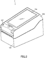
- FIG. 2 is a perspective view of the printer 1 of this embodiment.
- FIG. 3A shows a paper roll R housed in the printer 1 of this embodiment.
- FIG. 3B illustrates printing operation of the printer 1.
- the printer 1 of this embodiment includes a case 102, a cover 103, a display panel 14a, a platen roller 105, a thermal head 106, a housing chamber 108, and auxiliary rollers 113 and 117.
- the housing chamber 108 is provided within the case 102 to house the paper roll R.
- the cover 103 opens and closes the housing chamber 108 and is swingably supported at a shaft 131 by the case 102.
- the display panel 14a is provided to the outer side of the cover 103.
- the display panel 14a is, for example, a liquid crystal display panel with a touch panel function, and provides an input-output interface to a user in a state in which the cover 103 is closed.
- a platen roller 105 is axially supported in a manner rotatable in forward and reverse directions, on the downstream in the feeding direction of the case 102.
- the platen roller 105 is a feeding unit for feeding continuous paper CP rolled out from the paper roll R and is formed in such a manner as to extend in the width direction of the continuous paper CP.
- the auxiliary roller 113 is provided on the case 102 side, whereas the auxiliary roller 117 is provided on the cover 103 side. In the state in which the cover 103 is closed, the auxiliary rollers 113 and 117 face each other across the continuous paper CP and help feeding the continuous paper CP to the platen roller 105.
- the paper roll R is composed of a rolled continuous paper CP having a strip shape.
- the continuous paper CP includes a belt-shaped mount PM and multiple labels PL that are temporarily attached on the mount PM at a predetermined interval.
- the labels PL are made of thermal paper or plain paper in accordance with situations.
- a thermal paper has a surface (that is, a printing surface) formed with a thermal color developing layer that develops a specific color (e.g., black or red) when reaching a predetermined temperature region.
- the back surface of the label PL is an adhesive surface that is coated with an adhesive agent.
- a surface in contact with the adhesive surface of the labels PL of the mount PM is coated with a release agent, such as silicone, to provide easy peeling off of the labels PL.
- the continuous paper CP is rolled out from the paper roll R by rotation of the platen roller 105.
- the thermal head 106 is disposed to the cover 103 so as to face the platen roller 105 while the cover 103 is closed.
- the thermal head 106 prints information on a label PL of the continuous paper CP rolled out from the paper roll R and includes multiple heating elements that are arranged in a line. While the cover 103 is closed, the thermal head 106 and the platen roller 105 pinch the continuous paper CP therebetween.
- the continuous paper CP is rolled out from the paper roll R to the platen roller 105 while being held between the auxiliary rollers 113 and 117.
- the continuous paper CP that has been printed by the thermal head 106, which faces the platen roller 105, is discharged to the outside of the printer 1 from an issue port 107 as an opening between the cover 103 and the case 102 in the state in which the cover 103 is closed.
- FIG. 4 illustrates a flow of displaying screens in issuing a label PL by the printer 1 of this embodiment.
- a product list 201 having a list of multiple products appears as shown in a screen G1.
- This product list 201 enables looking through all products by a scroll operation.
- a screen G2 containing a product image 202 of the selected product PD appears.
- the product can be reselected by operating a button "RETURN TO PRODUCT SELECTION" to return to the screen G1.
- a screen G3 In response to a tap operation at the position where the product image 202 is displayed in the screen G2, a screen G3 appears.
- the screen G3 contains an affixing instruction image 203.
- the affixing instruction image 203 indicates an affixing position to the selected product PD of the label PL. This image enables an operator to visually recognize the affixing position to the selected product PD of the label.
- the printer 1 may include an audio output unit having a speaker.
- a voice sound "Affix to an upper left on the front surface.” may be output, or the affixing instruction image 203 may be displayed on the display panel 14a together with the audio output.
- the affixing position of the label may be explained in detail by audio that is output from the audio output unit.
- the screen G3 contains a button b1 ("ISSUE”) (example of operation content) and a button b2 ("RETURN TO PRODUCT SELECTION").
- ISSUE example of operation content
- button b2 RETURN TO PRODUCT SELECTION
- the label PL to be affixed to the selected product PD is issued.
- the product can be reselected by operating the button b2 to return to the screen G1.
- FIG. 4 shows an example of displaying the affixing instruction image 203 after the product image 202 is displayed
- the displaying order is not limited to this.
- the affixing instruction image 203 may be displayed without displaying the product image 202 after the product is selected in the product list 201.
- FIG. 4 shows an example of displaying the issue button (button b1) together with the affixing instruction image 203, but the contents of the screen are not limited to this.
- the issue button (button b1) may be shown after the affixing instruction image 203 is displayed.
- FIG. 5 is a block diagram showing an internal configuration of the printer 1 of this embodiment.
- FIG. 6 shows an example of data components of a product database.
- the printer 1 includes a control unit 11, a storage 12 (example of a storage), an operation input unit 13, a display unit 14, a motor drive unit 15, a head drive unit 16, and a communication unit 17.
- the control unit 11 includes a microcomputer and a memory (random access memory (RAM) or read only memory (ROM)) and controls operation of the printer 1.
- the microcomputer reads and executes various programs (including firmware and an affixing instruction program that is described later) stored in the memory, after the printer 1 is powered on.
- the storage 12 is a storage device, such as a solid state drive (SSD).
- SSD solid state drive
- the storage 12 stores data of a layout and a format of a label PL, which are read by the firmware in printing the label PL.
- the control unit 11 creates print data based on the data of the layout and the format of a label PL recorded in the storage 12 and sends a print instruction including the print data, to the motor drive unit 15 and the head drive unit 16.
- the storage 12 stores a product database, as shown by the example in FIG. 6 .
- Each record of the product database stores a value of each of fields "PRODUCT CODE”, “PRODUCT NAME”, “PRODUCT IMAGE”, “AFFIXING INSTRUCTION IMAGE”, and "PRINT CONTENTS”.
- the "PRODUCT CODE” field stores a value of a product code (example of item information) for identifying a product.
- the "PRODUCT NAME" field stores a value that shows a name of a product.
- the "PRODUCT IMAGE" field stores a value for specifying (or referring to) a product image.
- the product image is read, for example, in displaying the product image 202 in FIG. 4 .
- the "AFFIXING INSTRUCTION IMAGE" field stores a value for specifying (or referring to) an image (affixing instruction image) that indicates an affixing position to a product of a label.
- the affixing instruction image is read, for example, in displaying the affixing instruction image 203 in FIG. 4 .
- the affixing instruction image is an example of an image that shows an affixing position of a print medium.
- the affixing instruction image 203 is not limited to a still image and may be a video. In addition, the affixing instruction image 203 may also include audio irrespective of a still image or a video.
- the "PRINT CONTENTS" field can store any value that shows a content to be printed on a label, and for example, it stores a value that shows a manufacturer of product, price, color, model, or the like.
- the operation input unit 13 includes an input device, for example, having various operation buttons, or a touch panel input mechanism provided to the display panel 14a, and an input interface circuit for receiving operation input by a button operation or a touch panel operation.
- the operation input unit 13 is an example of a reception unit that receives a product code as item information.
- the display unit 14 includes a display panel 14a (refer to FIG. 2 ) and a driving circuit for displaying an image on the display panel 14a.
- the display unit 14 displays an execution result of the firmware and the affixing instruction program.
- the control unit 11 functions as the following units with the microcomputer executing the affixing instruction program.
- the control unit 11 is an example of a reception unit, an acquisition unit, and a display control unit.
- the unit (iii) preferably displays an issue button (example of operation content) of a label to be affixed on a product associated with the affixing instruction image, as shown in the screen G3 in FIG. 4 .
- An operator can issue a label immediately after checking the affixing position in the affixing instruction image or the like, thereby being able to affix the label on the product before forgetting the affixing position.
- the motor drive unit 15 drives a stepping motor (not shown) that controls rotation of the platen roller 105, to draw and feed the continuous paper P from the paper roll R housed in the printer 1.
- the motor drive unit 15 feeds the continuous paper CP by a feeding amount and in the feeding direction (forward or reverse direction) that are specified by a print instruction from the control unit 11.
- the specified feeding direction and feeding amount correspond to, for example, the rotation direction and the number of steps of the stepping motor.
- the motor drive unit 15 drives the stepping motor based on the rotation direction and the number of steps.
- the head drive unit 16 causes electric current to selectively flow to each heating element of the thermal head 106 upon receiving a print instruction including print data from the control unit 11.
- the heating element that generates heat by electric current is pressed against the label PL, which is fed by the platen roller 105. This causes the part of the label PL, against which the heating element is pressed, to develop color, whereby the label PL is printed.
- the head drive unit 16 is an example of a print unit.
- the communication unit 17 includes a communication interface circuit for communicating with an external device.
- the communication unit 17 sends and receives information with an external device by a wired communication via a communication cable or the like, or by a wireless communication.
- the printer 1 of this embodiment is used such that an operator inputs to select a specific product on the display panel 14a first in issuing a label to be affixed on the product.
- the control unit 11 of the printer 1 reads the affixing instruction image or the like corresponding to the selected product code from the product database and displays it on the display panel 14a.
- the operator can visually recognize the affixing position on the product of the label to be issued.
- the label corresponding to the selected product is issued in response to the operator operating the issue button.
- the operator recognizes the affixing position of the label at this time, and therefore, the possibility of occurrence of affixing position failure can be reduced in affixing the issued label on the product.
- a printer 1 being a mobile printer that can be carried
- works of issuing labels of a wide variety of products and affixing the labels thereto are performed by an operator, for example, while the operator moves in a warehouse. Even in such a case, affixing position failure by the operator can be reduced because an affixing work can be easily performed by checking the affixing position of each product in the affixing instruction image that is displayed on the printer 1 each time of issuing a label.
- FIG. 7 shows an example of using the printer 1A according to the second embodiment.
- the printer 1A of this embodiment differs from the printer 1 of the first embodiment in that a code scanner 18 (example of a reader) is connected via a communication cable 110.
- the code scanner 18 may communicate with the printer 1 via wireless communication.
- an operator uses the code scanner 18 to, for example, scan code information C corresponding to each of multiple products printed on an input paper MP.
- a bar code including a corresponding product code, a character string showing a product name, etc. are printed as the code information C.
- the communication unit 17 of the printer 1A of this embodiment communicates with the code scanner 18 that reads the code information C.
- the control unit 11 (example of a reception unit of this embodiment) of the printer 1A inputs a product code that the communication unit 17 receives from the code scanner 18, and it performs processing similar to that in the first embodiment. That is, the control unit 11 functions as a reception unit that receives a product code as item information, based on the code information C that is received by the communication unit 17 from the code scanner 18.
- the code scanner 18 includes a light source, such as an LED, an optical mechanism, an image sensor, and a digital processing circuit.
- the code scanner 18 emits light that is output from the light source, to a bar code of external code information C.
- the light that is reflected back from the bar code is imaged by the image sensor via the optical mechanism.
- the digital processing circuit of the code scanner 18 digitizes and analyzes a signal that is photoelectrically converted by the image sensor, and it extracts (reads) a product code contained in the bar code.
- the communication unit 17 receives the product code that is sent from the code scanner 18. Operation of the printer 1A after the product code is read is the same as that of the printer 1 of the first embodiment. That is, the control unit 11 of the printer 1A causes displaying a product image 202 and an affixing instruction image 203 (refer to FIG. 4 ) corresponding to the read product code and issues a label PL in response to operation to the issue button.
- the printer 1A of this embodiment eliminates the need for an operator to display a product list 201 on the display panel 14a. In one example, it is possible for an operator to display an affixing instruction image or the like, with easy operation, after checking a product name printed on the input paper MP.
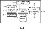
- FIG. 8 is a block diagram showing an internal configuration of the printer 1B of this embodiment.
- FIG. 9 shows a structural example of a label PL used in the printer 1B of this embodiment.
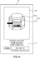
- FIG. 10 shows an example of a screen displayed on the printer 1B of this embodiment.
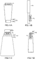
- FIGs. 11A to 11D show examples of an affixing position to a product of a label PL issued by the printer 1B of this embodiment.
- the printer 1B of this embodiment further includes an RFID interrogator 19, relative to the printer 1 (refer to FIG. 5 ) of the first embodiment.
- the interrogator 19 is an example of an RFID reader and an RFID writer.
- the interrogator 19 reads and writes data in a radio frequency identification (RFID) inlay.
- RFID radio frequency identification
- a label PL that is used in the printer 1B of this embodiment has an inlay INL.
- the inlay INL is, for example, embedded in a label PL.
- the inlay INL is composed of an IC chip 401 and a thin film antenna that is coupled to the IC chip 401.
- the inlay INL communicates with the interrogator 19 and writes product data in the IC chip 401 at the time of issuing a label PL.
- the product data contains at least a product code and a product name, and may also include accompanying data relating to a product, such as a lot number, an expiration date, etc. of a product.
- the interrogator 19 includes an antenna for wirelessly communicating with the inlay INL of the label PL and includes an interrogator (reader/writer) connected to the antenna. These antenna and interrogator are provided in the vicinity of the feeding path of the continuous paper CP in the printer 1B.
- the interrogator 19 writes (encodes) data in the inlay INL around the time when a label PL is printed.
- the IC chip 401 of the inlay INL is able to store a great amount of data in contrast with a bar code and the like. From this point of view, affixing a label PL with an embedded inlay INL to a product is advantageous in ensuring good traceability of the product.
- the antenna of the inlay INL is susceptible to surrounding environment.
- a label PL is affixed to a conductive material, such as a metal part of a product, or a product contains liquid (e.g., a bottle of skin lotion)
- a communicable range is drastically reduced, and in the worst case, communication cannot be performed.
- attention should be paid so as to not affix it to an incorrect position.
- FIG. 10 shows a screen G4 containing an affixing instruction image 203 that is displayed on the display panel 14a, of the printer 1B of this embodiment.
- This screen G4 corresponds to the screen G3 in FIG. 4 .
- the product PD has a body 301 and a cap 302, the body 301 is a glass bottle, and the cap 302 is made of metal, such as aluminum.
- the affixing position is preferably indicated by an arrow in the affixing instruction image 203. That is, preferably, the arrow indicating the affixing position is also a part of the affixing instruction image 203.
- the affixing instruction image 203 is not limited to a still image and may be a video.
- the text Tx1 is stored in the product database ( FIG. 6 ) in association with the affixing instruction image 203.
- the text Tx1 is read from the product database together with the associated affixing instruction image 203.
- the affixing instruction image 203 may be associated with audio irrespective of a still image or a video. In this case, at the time the affixing instruction image 203 appears on the display panel 14a, the audio associated with the affixing instruction image 203 is reproduced.
- FIGs. 11A to 11D show affixing instruction images of products PD having various forms, for labels PL with an embedded inlay INL.
- the product PD in FIG. 11A is a tubular cosmetic, and it has a body 303 and a cap 304.
- the body 303 is made of resin, but contains materials including a metal component.
- an instruction is made to affix the label PL so that the inlay INL will protrude from the body 303, whereby reduction in communication performance of the inlay INL is suppressed.
- the product PD in FIG. 11B is a pencil type cosmetic and is assumed to have a surface entirely made of metal. In this case, an instruction is made to affix the label PL so that the inlay INL will protrude from the product PD, whereby reduction in communication performance of the inlay INL is suppressed.
- the product PD in FIG. 11C has a shape of a pump bottle and is assumed to have a resin body 305 and a resin cap 306. In this case, even if the content contains a metal material, reduction in communication performance of the inlay INL is suppressed by instructing to affix to the cap 306.
- the product PD in FIG. 11D is a nail cosmetic and has a body 307 and a cap 308. It is assumed that the body 307 contains materials including a metal material. Also in this case, reduction in communication performance of the inlay INL is suppressed by instructing to affix to the cap 308.
- printer 1B of this embodiment enables reducing the possibility of occurrence of affixing position failure in affixing an issued label to a product. Thus, deterioration in communication performance of the inlay contained in the label can be suppressed.
- the first embodiment describes a case in which the product database is recorded in the storage 12 of the printer 1, but a location where the product database is recorded is not limited to this.
- the product database may be recorded in other device that is communicable with the printer 1.
- an information processing system 6 shown in FIG. 12 includes the printer 1 of the first embodiment and a server 5 that can communicate with the printer 1 via a network NW, such as the Internet or an intranet.
- the product database may be recorded in the server 5.
- the control unit 11 of the printer 1 functions as an inquiry unit that sends to the server 5 an inquiry with a received product code via the communication unit 17.
- the server 5 When receiving the inquiry from the printer 1, the server 5 refers to the product database and sends to the printer 1 an affixing instruction image or the like associated with the product code in the inquiry. Then, the control unit 11 of the printer 1 functions as an acquisition unit that acquires the affixing instruction image or the like from the server 5 via the communication unit 17. Moreover, the control unit 11 causes the display panel 14a to display the acquired affixing instruction image or the like.
- the affixing instruction image itself may not be sent from the server 5 to the printer 1, and instead, identification information for identifying the affixing instruction image or the like may be sent.
- identification information for identifying the affixing instruction image or the like may be sent.
- multiple affixing instruction images or the like corresponding to identification information are stored in the printer 1, and an affixing instruction image corresponding to received identification information is displayed on the display panel 14a.
- the printer 1A which is described in relation to the second embodiment (refer to FIG. 8 ; the printer connected to the code scanner 18), is connected to a server 5 that is communicable via a network NW.
- a label PL containing an inlay INL is used, and the printer 1A prints information relating to a product, on the label PL, and writes (namely, encodes) electronic product code (EPC) data as a standard identification code, in the inlay INL.
- EPC electronic product code
- a bar code that is read by the code scanner 18 contains stock keeping unit (SKU) data.
- SKU data may be, for example, a code (company prefix) showing a company name and a code (product code; commodity code or commodity group code) classifying a product.
- the server 5 stores a product database that contains EPC data to be encoded in an inlay INL and an affixing instruction image or the like, in association with the SKU data.
- the printer 1A inquires the server 5 based on the SKU data received from the code scanner 18.
- the server 5 refers to the product database to read the EPC data and the affixing instruction image or the like corresponding to the SKU data on which the inquiry is based, and then it sends these data to the printer 1A.
- the control unit 11 of the printer 1A controls the interrogator 19 so that the EPC data will be encoded in the inlay INL around the time of printing a label PL.
- the control unit 11 controls so that the bar code (that is, the bar code read by the code scanner 18) corresponding to the SKU data will be printed on a label.
- the control unit 11 of the printer 1A controls the display unit 14 so that the affixing instruction image or the like received from the server 5 will be displayed on the display panel 14a.
- the server 5 may create EPC data based on the SKU data received from the printer 1A and send the created EPC data to the printer 1A.
- the function of the server 5 can also be implemented by the printer 1A.
- the printer 1A stores the product database and displays the affixing instruction image or the like on the display panel 14a without inquiring the server 5.
- This embodiment describes an information processing system in which the printer 1B referred to in the third embodiment is communicable with a server 5 via a network NW, as shown in FIG. 12 .
- the server 5 of this embodiment stores a product database that contains a tag ID (TID) unique to an inlay INL and an affixing instruction image or the like of a product, in a manner associated with each other.
- TID tag ID
- the TID (example of identification information unique to an RFID inlay) is a unique code stored in an IC chip of an inlay and is data that cannot be overwritten at the time of encoding by the printer.
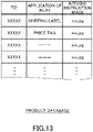
- FIG. 13 shows an example of data components of a product database according to an example of this embodiment.
- each record of the product database stores a value of each of fields "TID”, "APPLICATION OF INLAY", and "AFFIXING INSTRUCTION IMAGE".
- the applications of an inlay include applications of a label itself, such as a shipping label and a price tag, in the example shown in FIG. 13 , they may be categories (for example, cosmetics, camera, etc.) of products to which labels are affixed.
- the product database may store communication setting information (communication parameters), such as size of a label, feed distance, communication feed speed, and electromagnetic wave level, in association with the TID.
- the feed distance means a feed distance necessary for a label to reach a communication region with the interrogator 19 in the printer 1B.
- the communication feed speed means a feed speed at which the communication region with the interrogator 19 is passed through in the printer 1B.
- the electromagnetic wave level is data relating to the intensity of electromagnetic waves emitted from the interrogator 19.
- the printer 1B causes the interrogator 19 to read a TID from one or each of multiple inlays while a label is rolled out from the roll and is fed though the path. Then, the control unit 11 of the printer 1B inquires the server 5 based on the TID read by the interrogator 19.
- the server 5 When receiving an inquiry from the printer 1B, the server 5refers to the product database to read an affixing instruction image or the like corresponding to the TID on which the inquiry is based, and then sends it to the printer 1B.
- the control unit 11 of the printer 1B controls the display unit 14 so that the affixing instruction image or the like acquired from the server 5 will be displayed on the display panel 14a.
- FIG. 13 shows a case in which the affixing instruction images or the like are recorded in association with the TIDs in the product database, but the data components are not limited thereto.
- a product or a category of a product to which a label containing an inlay is to be affixed can be presumed from a TID in some cases.
- the product database contains a product or a product category and an affixing instruction image or the like in associated with each other.
- the server 5 presumes a product or a product category from the TID received from the printer 1B and sends an affixing instruction image or the like corresponding to the presumed product or the product category, to the printer 1B.
- the function of the server 5 can also be implemented by the printer 1B.
- the printer 1B stores the product database and displays the affixing instruction image or the like on the display panel 14a without inquiring the server 5.
- an imaging unit may be used in order to identify a product.
- an imaging unit may be installed in the printer 1 or connected to the printer 1 with a wired or wireless connection for example, and an affixing instruction image or the like of a product may be displayed based on an image of the product that is obtained by the imaging unit.
- the control unit 11 of the printer 1 may presume a product from shape, size, material, or another factor, based on the obtained image of the product, by an image presumption technique using artificial intelligence (AI) or the like. Then, the control unit 11 may acquire, from the product database, an affixing instruction image or the like corresponding to the presumed product and may display the acquired data.
- AI artificial intelligence
- the fifth and the sixth embodiments describe a case in which the product database is stored in the server 5, but the storage location is not limited to this.
- the product database may be provided in each of the printers 1A and 1B.
- each of the printers 1A and 1B may display an affixing instruction image without inquiring the server 5.
Landscapes
- Engineering & Computer Science (AREA)
- Theoretical Computer Science (AREA)
- Human Computer Interaction (AREA)
- General Engineering & Computer Science (AREA)
- Physics & Mathematics (AREA)
- General Physics & Mathematics (AREA)
- Business, Economics & Management (AREA)
- Multimedia (AREA)
- Signal Processing (AREA)
- Quality & Reliability (AREA)
- Economics (AREA)
- Development Economics (AREA)
- Strategic Management (AREA)
- Accounting & Taxation (AREA)
- Entrepreneurship & Innovation (AREA)
- Human Resources & Organizations (AREA)
- Marketing (AREA)
- Operations Research (AREA)
- Finance (AREA)
- Tourism & Hospitality (AREA)
- General Business, Economics & Management (AREA)
- Accessory Devices And Overall Control Thereof (AREA)
- Labeling Devices (AREA)
- Printers Characterized By Their Purpose (AREA)
- Record Information Processing For Printing (AREA)
- User Interface Of Digital Computer (AREA)
Abstract
Description
- The present invention relates to a printer and a program.
- Among printers for issuing labels to be affixed on products, printers configured to display preview images of labels to be issued are conventionally known (for example,
Japanese Unexamined Patent Application Laid-Open No. 2013-203013 - In one example in which an operator affixes labels on items in an item factory or an inventory warehouse, although the affixing positions of labels are determined by operation procedures, affixing position failure occurs in some cases. In particular, in a situation in which labels are affixed to a wide variety of items having different affixing positions, affixing position failure easily occurs.
- In view of this, an object of the present invention is to reduce the possibility of occurrence of affixing position failure in affixing a print medium, such as a label, to an item.
- A printer configured to print information on a print medium and issue the printed print medium, the printer comprising a storage configured to store affixing position information relating to an affixing position in affixing the print medium to an item, in association with item information for identifying the item; a reception unit configured to receive input of the item information; an acquisition unit configured to acquire from the storage the affixing position information associated with the item information, based on the item information received by the reception unit; and a display control unit configured to cause a display unit to display the affixing position information that is acquired by the acquisition unit.
- One aspect of the present invention enables reducing the possibility of occurrence of affixing position failure in affixing a print medium to an item.
-
-
FIG. 1 is a font view of a group of products with attached labels that are issued by a printer of a first embodiment. -
FIG. 2 is a perspective view of the printer of the first embodiment. -
FIG. 3A shows a paper roll housed in the printer of the first embodiment. -
FIG. 3B illustrates printing operation of the printer. -
FIG. 4 illustrates a flow of displaying screens on the printer of the first embodiment. -
FIG. 5 is a block diagram showing an internal configuration of the printer of the first embodiment. -
FIG. 6 shows an example of data components of a product database. -
FIG. 7 shows an example of using a printer according to a second embodiment. -
FIG. 8 is a block diagram showing an internal configuration of a printer of a third embodiment. -
FIG. 9 shows a structural example of a label used in the printer of the third embodiment. -
FIG. 10 shows an example of a screen displayed on the printer of the third embodiment. -
FIGs. 11A to 11D show examples of an affixing position to a product of a label issued by the printer of the third embodiment. -
FIG. 12 schematically shows a system including a printer and a server. -
FIG. 13 shows an example of data components of a product database according to a fifth embodiment. - The term "item" in this disclosure means a tangible entity, such as a finished article, a half-finished product (intermediate product in the midst of manufacturing), or a product. The following embodiments describe a product as an example of the item.
- In each of the following embodiments, the printer can be used as a desktop printer or a mobile printer (portable printer). An affixing instruction image, which is described later, can be displayed on a relatively small display panel used in a mobile printer.
- A use application of labels issued by a
printer 1 according to this embodiment is shown inFIG. 1. FIG. 1 is a font view of a group of products with attached labels that are issued by the printer of this embodiment. -
FIG. 1 shows a state in which multiple products PD each having an attached label PL are placed on pallets PT. The labels PL are affixed to the same positions on the products PD so as to each face the front side in the state in which the products PD are placed on the pallets PT. The aligned affixing positions of the labels PL, as shown inFIG. 1 , are convenient for an operator to, for example, perform an inspection work on many products PD, such as in a factory or a warehouse. - In consideration of this, in order to prevent an operator from affixing a label PL to an incorrect position on a product PD, the
printer 1 of this embodiment displays an image, such as an image for indicating an affixing position of a label PL, at the time of issuing the label PL. - Hereinafter, a structure of the
printer 1 of this embodiment will be described with reference toFIGs. 2 to 3B .FIG. 2 is a perspective view of theprinter 1 of this embodiment.FIG. 3A shows a paper roll R housed in theprinter 1 of this embodiment.FIG. 3B illustrates printing operation of theprinter 1. - As shown in
FIGs. 2 and3B , theprinter 1 of this embodiment includes acase 102, acover 103, adisplay panel 14a, aplaten roller 105, athermal head 106, ahousing chamber 108, andauxiliary rollers 113 and 117. - As shown in
FIG. 3B , thehousing chamber 108 is provided within thecase 102 to house the paper roll R. Thecover 103 opens and closes thehousing chamber 108 and is swingably supported at ashaft 131 by thecase 102. - As shown in
FIG. 2 , thedisplay panel 14a is provided to the outer side of thecover 103. Thedisplay panel 14a is, for example, a liquid crystal display panel with a touch panel function, and provides an input-output interface to a user in a state in which thecover 103 is closed. - As shown in
FIG. 3B , aplaten roller 105 is axially supported in a manner rotatable in forward and reverse directions, on the downstream in the feeding direction of thecase 102. Theplaten roller 105 is a feeding unit for feeding continuous paper CP rolled out from the paper roll R and is formed in such a manner as to extend in the width direction of the continuous paper CP. Theauxiliary roller 113 is provided on thecase 102 side, whereas the auxiliary roller 117 is provided on thecover 103 side. In the state in which thecover 103 is closed, theauxiliary rollers 113 and 117 face each other across the continuous paper CP and help feeding the continuous paper CP to theplaten roller 105. - As shown in
FIG. 3A , the paper roll R is composed of a rolled continuous paper CP having a strip shape. In the example in the drawing, the continuous paper CP includes a belt-shaped mount PM and multiple labels PL that are temporarily attached on the mount PM at a predetermined interval. The labels PL are made of thermal paper or plain paper in accordance with situations. A thermal paper has a surface (that is, a printing surface) formed with a thermal color developing layer that develops a specific color (e.g., black or red) when reaching a predetermined temperature region. The back surface of the label PL is an adhesive surface that is coated with an adhesive agent. A surface in contact with the adhesive surface of the labels PL of the mount PM is coated with a release agent, such as silicone, to provide easy peeling off of the labels PL. - In the
printer 1 of this embodiment, the continuous paper CP is rolled out from the paper roll R by rotation of theplaten roller 105. - The
thermal head 106 is disposed to thecover 103 so as to face theplaten roller 105 while thecover 103 is closed. Thethermal head 106 prints information on a label PL of the continuous paper CP rolled out from the paper roll R and includes multiple heating elements that are arranged in a line. While thecover 103 is closed, thethermal head 106 and theplaten roller 105 pinch the continuous paper CP therebetween. - As shown in
FIG. 3B , in the state in which thecover 103 is closed, in response to theplaten roller 105 driven in the forward direction, the continuous paper CP is rolled out from the paper roll R to theplaten roller 105 while being held between theauxiliary rollers 113 and 117. The continuous paper CP that has been printed by thethermal head 106, which faces theplaten roller 105, is discharged to the outside of theprinter 1 from anissue port 107 as an opening between thecover 103 and thecase 102 in the state in which thecover 103 is closed. - Next, display examples of the
printer 1 of this embodiment will be described with reference toFIG. 4. FIG. 4 illustrates a flow of displaying screens in issuing a label PL by theprinter 1 of this embodiment. - In response to a predetermined operation on the
display panel 14a of theprinter 1, aproduct list 201 having a list of multiple products appears as shown in a screen G1. Thisproduct list 201 enables looking through all products by a scroll operation. In response to an operation to select any one of the products in the product list 201 (herein, a tap operation for selecting a "PERSONAL COMPUTER ABC"), a screen G2 containing aproduct image 202 of the selected product PD appears. - The product can be reselected by operating a button "RETURN TO PRODUCT SELECTION" to return to the screen G1.
- In response to a tap operation at the position where the
product image 202 is displayed in the screen G2, a screen G3 appears. The screen G3 contains an affixinginstruction image 203. The affixinginstruction image 203 indicates an affixing position to the selected product PD of the label PL. This image enables an operator to visually recognize the affixing position to the selected product PD of the label. - The
printer 1 may include an audio output unit having a speaker. In this case, for example, a voice sound "Affix to an upper left on the front surface." may be output, or the affixinginstruction image 203 may be displayed on thedisplay panel 14a together with the audio output. In another example, while a video for showing the affixing position of the label in different displaying forms from various angles of the product PD is reproduced on thedisplay panel 14a, the affixing position of the label may be explained in detail by audio that is output from the audio output unit. - The screen G3 contains a button b1 ("ISSUE") (example of operation content) and a button b2 ("RETURN TO PRODUCT SELECTION"). In response to a tap operation to the button b1, the label PL to be affixed to the selected product PD is issued. The product can be reselected by operating the button b2 to return to the screen G1.
- Although
FIG. 4 shows an example of displaying the affixinginstruction image 203 after theproduct image 202 is displayed, the displaying order is not limited to this. The affixinginstruction image 203 may be displayed without displaying theproduct image 202 after the product is selected in theproduct list 201. -
FIG. 4 shows an example of displaying the issue button (button b1) together with the affixinginstruction image 203, but the contents of the screen are not limited to this. The issue button (button b1) may be shown after the affixinginstruction image 203 is displayed. - Next, an example of an internal configuration of the
printer 1 of this embodiment will be described with reference toFIGs. 5 and6 .FIG. 5 is a block diagram showing an internal configuration of theprinter 1 of this embodiment.FIG. 6 shows an example of data components of a product database. - With reference to
FIG. 5 , theprinter 1 includes acontrol unit 11, a storage 12 (example of a storage), anoperation input unit 13, adisplay unit 14, amotor drive unit 15, ahead drive unit 16, and acommunication unit 17. - The
control unit 11 includes a microcomputer and a memory (random access memory (RAM) or read only memory (ROM)) and controls operation of theprinter 1. The microcomputer reads and executes various programs (including firmware and an affixing instruction program that is described later) stored in the memory, after theprinter 1 is powered on. - The
storage 12 is a storage device, such as a solid state drive (SSD). Thestorage 12 stores data of a layout and a format of a label PL, which are read by the firmware in printing the label PL. - The
control unit 11 creates print data based on the data of the layout and the format of a label PL recorded in thestorage 12 and sends a print instruction including the print data, to themotor drive unit 15 and thehead drive unit 16. - The
storage 12 stores a product database, as shown by the example inFIG. 6 . Each record of the product database stores a value of each of fields "PRODUCT CODE", "PRODUCT NAME", "PRODUCT IMAGE", "AFFIXING INSTRUCTION IMAGE", and "PRINT CONTENTS". - The "PRODUCT CODE" field stores a value of a product code (example of item information) for identifying a product.
- The "PRODUCT NAME" field stores a value that shows a name of a product.
- The "PRODUCT IMAGE" field stores a value for specifying (or referring to) a product image. The product image is read, for example, in displaying the
product image 202 inFIG. 4 . - The "AFFIXING INSTRUCTION IMAGE" field stores a value for specifying (or referring to) an image (affixing instruction image) that indicates an affixing position to a product of a label. The affixing instruction image is read, for example, in displaying the affixing
instruction image 203 inFIG. 4 . The affixing instruction image is an example of an image that shows an affixing position of a print medium. The affixinginstruction image 203 is not limited to a still image and may be a video. In addition, the affixinginstruction image 203 may also include audio irrespective of a still image or a video. - The "PRINT CONTENTS" field can store any value that shows a content to be printed on a label, and for example, it stores a value that shows a manufacturer of product, price, color, model, or the like.
- The
operation input unit 13 includes an input device, for example, having various operation buttons, or a touch panel input mechanism provided to thedisplay panel 14a, and an input interface circuit for receiving operation input by a button operation or a touch panel operation. Theoperation input unit 13 is an example of a reception unit that receives a product code as item information. - The
display unit 14 includes adisplay panel 14a (refer toFIG. 2 ) and a driving circuit for displaying an image on thedisplay panel 14a. Thedisplay unit 14 displays an execution result of the firmware and the affixing instruction program. - The
control unit 11 functions as the following units with the microcomputer executing the affixing instruction program. - (i) A reception unit that receives input of a product code (example of item information)
- (ii) An acquisition unit that accesses a product database to acquire an affixing instruction image (example of affixing position information) associated with the input product code
- (iii) A display control unit that displays the acquired affixing instruction image on the
display panel 14a - The
control unit 11 is an example of a reception unit, an acquisition unit, and a display control unit. - The unit (iii) preferably displays an issue button (example of operation content) of a label to be affixed on a product associated with the affixing instruction image, as shown in the screen G3 in
FIG. 4 . An operator can issue a label immediately after checking the affixing position in the affixing instruction image or the like, thereby being able to affix the label on the product before forgetting the affixing position. - The
motor drive unit 15 drives a stepping motor (not shown) that controls rotation of theplaten roller 105, to draw and feed the continuous paper P from the paper roll R housed in theprinter 1. - The
motor drive unit 15 feeds the continuous paper CP by a feeding amount and in the feeding direction (forward or reverse direction) that are specified by a print instruction from thecontrol unit 11. The specified feeding direction and feeding amount correspond to, for example, the rotation direction and the number of steps of the stepping motor. Themotor drive unit 15 drives the stepping motor based on the rotation direction and the number of steps. - The
head drive unit 16 causes electric current to selectively flow to each heating element of thethermal head 106 upon receiving a print instruction including print data from thecontrol unit 11. The heating element that generates heat by electric current is pressed against the label PL, which is fed by theplaten roller 105. This causes the part of the label PL, against which the heating element is pressed, to develop color, whereby the label PL is printed. Thehead drive unit 16 is an example of a print unit. - The
communication unit 17 includes a communication interface circuit for communicating with an external device. Thecommunication unit 17 sends and receives information with an external device by a wired communication via a communication cable or the like, or by a wireless communication. - The
printer 1 of this embodiment is used such that an operator inputs to select a specific product on thedisplay panel 14a first in issuing a label to be affixed on the product. In response to the selection input, thecontrol unit 11 of theprinter 1 reads the affixing instruction image or the like corresponding to the selected product code from the product database and displays it on thedisplay panel 14a. Thus, the operator can visually recognize the affixing position on the product of the label to be issued. Under these conditions, the label corresponding to the selected product is issued in response to the operator operating the issue button. The operator recognizes the affixing position of the label at this time, and therefore, the possibility of occurrence of affixing position failure can be reduced in affixing the issued label on the product. - In particular, as to a
printer 1 being a mobile printer that can be carried, works of issuing labels of a wide variety of products and affixing the labels thereto are performed by an operator, for example, while the operator moves in a warehouse. Even in such a case, affixing position failure by the operator can be reduced because an affixing work can be easily performed by checking the affixing position of each product in the affixing instruction image that is displayed on theprinter 1 each time of issuing a label. - A
printer 1A according to a second embodiment will be described with reference toFIG. 7. FIG. 7 shows an example of using theprinter 1A according to the second embodiment. - The
printer 1A of this embodiment differs from theprinter 1 of the first embodiment in that a code scanner 18 (example of a reader) is connected via acommunication cable 110. Thecode scanner 18 may communicate with theprinter 1 via wireless communication. - As shown in
FIG. 7 , an operator uses thecode scanner 18 to, for example, scan code information C corresponding to each of multiple products printed on an input paper MP. A bar code including a corresponding product code, a character string showing a product name, etc. are printed as the code information C. - The
communication unit 17 of theprinter 1A of this embodiment communicates with thecode scanner 18 that reads the code information C. The control unit 11 (example of a reception unit of this embodiment) of theprinter 1A inputs a product code that thecommunication unit 17 receives from thecode scanner 18, and it performs processing similar to that in the first embodiment. That is, thecontrol unit 11 functions as a reception unit that receives a product code as item information, based on the code information C that is received by thecommunication unit 17 from thecode scanner 18. - The
code scanner 18 includes a light source, such as an LED, an optical mechanism, an image sensor, and a digital processing circuit. Thecode scanner 18 emits light that is output from the light source, to a bar code of external code information C. The light that is reflected back from the bar code is imaged by the image sensor via the optical mechanism. The digital processing circuit of thecode scanner 18 digitizes and analyzes a signal that is photoelectrically converted by the image sensor, and it extracts (reads) a product code contained in the bar code. - The
communication unit 17 receives the product code that is sent from thecode scanner 18. Operation of theprinter 1A after the product code is read is the same as that of theprinter 1 of the first embodiment. That is, thecontrol unit 11 of theprinter 1A causes displaying aproduct image 202 and an affixing instruction image 203 (refer toFIG. 4 ) corresponding to the read product code and issues a label PL in response to operation to the issue button. - The
printer 1A of this embodiment eliminates the need for an operator to display aproduct list 201 on thedisplay panel 14a. In one example, it is possible for an operator to display an affixing instruction image or the like, with easy operation, after checking a product name printed on the input paper MP. - Next, a
printer 1B according to a third embodiment will be described with reference toFIGs. 8 to 11D . -
FIG. 8 is a block diagram showing an internal configuration of theprinter 1B of this embodiment.FIG. 9 shows a structural example of a label PL used in theprinter 1B of this embodiment.FIG. 10 shows an example of a screen displayed on theprinter 1B of this embodiment.FIGs. 11A to 11D show examples of an affixing position to a product of a label PL issued by theprinter 1B of this embodiment. - Matters that are not particularly described as to the
printer 1B of this embodiment are the same as those for theprinter 1 of the first embodiment, and duplicated description will be omitted. - As shown in
FIG. 8 , theprinter 1B of this embodiment further includes anRFID interrogator 19, relative to the printer 1 (refer toFIG. 5 ) of the first embodiment. Theinterrogator 19 is an example of an RFID reader and an RFID writer. Theinterrogator 19 reads and writes data in a radio frequency identification (RFID) inlay. - As shown in
FIG. 9 , a label PL that is used in theprinter 1B of this embodiment has an inlay INL. The inlay INL is, for example, embedded in a label PL. The inlay INL is composed of anIC chip 401 and a thin film antenna that is coupled to theIC chip 401. The inlay INL communicates with theinterrogator 19 and writes product data in theIC chip 401 at the time of issuing a label PL. The product data contains at least a product code and a product name, and may also include accompanying data relating to a product, such as a lot number, an expiration date, etc. of a product. - Although not shown in the drawing, the
interrogator 19 includes an antenna for wirelessly communicating with the inlay INL of the label PL and includes an interrogator (reader/writer) connected to the antenna. These antenna and interrogator are provided in the vicinity of the feeding path of the continuous paper CP in theprinter 1B. Theinterrogator 19 writes (encodes) data in the inlay INL around the time when a label PL is printed. - The
IC chip 401 of the inlay INL is able to store a great amount of data in contrast with a bar code and the like. From this point of view, affixing a label PL with an embedded inlay INL to a product is advantageous in ensuring good traceability of the product. - On the other hand, the antenna of the inlay INL is susceptible to surrounding environment. For example, in a case in which a label PL is affixed to a conductive material, such as a metal part of a product, or a product contains liquid (e.g., a bottle of skin lotion), a communicable range is drastically reduced, and in the worst case, communication cannot be performed. In consideration of this, in affixing a label PL with an embedded inlay INL to a product, attention should be paid so as to not affix it to an incorrect position.
- In one example,
FIG. 10 shows a screen G4 containing an affixinginstruction image 203 that is displayed on thedisplay panel 14a, of theprinter 1B of this embodiment. This screen G4 corresponds to the screen G3 inFIG. 4 . - In the screen G4, it is assumed that the product PD has a
body 301 and acap 302, thebody 301 is a glass bottle, and thecap 302 is made of metal, such as aluminum. In this case, it is preferable to display a text Tx1 that instructs to avoid thecap 302 and affix to thebody 301, as an affixing position. In addition to this, the affixing position is preferably indicated by an arrow in the affixinginstruction image 203. That is, preferably, the arrow indicating the affixing position is also a part of the affixinginstruction image 203. The affixinginstruction image 203 is not limited to a still image and may be a video. - In order to display a text Tx1 or the like, which shows an affixing position including notes, etc., the text Tx1 is stored in the product database (
FIG. 6 ) in association with the affixinginstruction image 203. When being displayed on thedisplay panel 14a, the text Tx1 is read from the product database together with the associated affixinginstruction image 203. - In addition, the affixing
instruction image 203 may be associated with audio irrespective of a still image or a video. In this case, at the time the affixinginstruction image 203 appears on thedisplay panel 14a, the audio associated with the affixinginstruction image 203 is reproduced. -
FIGs. 11A to 11D show affixing instruction images of products PD having various forms, for labels PL with an embedded inlay INL. - The product PD in
FIG. 11A is a tubular cosmetic, and it has abody 303 and acap 304. Herein, it is assumed that thebody 303 is made of resin, but contains materials including a metal component. In this case, an instruction is made to affix the label PL so that the inlay INL will protrude from thebody 303, whereby reduction in communication performance of the inlay INL is suppressed. - The product PD in
FIG. 11B is a pencil type cosmetic and is assumed to have a surface entirely made of metal. In this case, an instruction is made to affix the label PL so that the inlay INL will protrude from the product PD, whereby reduction in communication performance of the inlay INL is suppressed. - The product PD in
FIG. 11C has a shape of a pump bottle and is assumed to have aresin body 305 and aresin cap 306. In this case, even if the content contains a metal material, reduction in communication performance of the inlay INL is suppressed by instructing to affix to thecap 306. - The product PD in
FIG. 11D is a nail cosmetic and has a body 307 and acap 308. It is assumed that the body 307 contains materials including a metal material. Also in this case, reduction in communication performance of the inlay INL is suppressed by instructing to affix to thecap 308. - Use of the
printer 1B of this embodiment enables reducing the possibility of occurrence of affixing position failure in affixing an issued label to a product. Thus, deterioration in communication performance of the inlay contained in the label can be suppressed. - For example, the first embodiment describes a case in which the product database is recorded in the
storage 12 of theprinter 1, but a location where the product database is recorded is not limited to this. The product database may be recorded in other device that is communicable with theprinter 1. In one example, aninformation processing system 6 shown inFIG. 12 includes theprinter 1 of the first embodiment and aserver 5 that can communicate with theprinter 1 via a network NW, such as the Internet or an intranet. In this case, the product database may be recorded in theserver 5. As necessary, thecontrol unit 11 of theprinter 1 functions as an inquiry unit that sends to theserver 5 an inquiry with a received product code via thecommunication unit 17. - When receiving the inquiry from the
printer 1, theserver 5 refers to the product database and sends to theprinter 1 an affixing instruction image or the like associated with the product code in the inquiry. Then, thecontrol unit 11 of theprinter 1 functions as an acquisition unit that acquires the affixing instruction image or the like from theserver 5 via thecommunication unit 17. Moreover, thecontrol unit 11 causes thedisplay panel 14a to display the acquired affixing instruction image or the like. - The affixing instruction image itself may not be sent from the
server 5 to theprinter 1, and instead, identification information for identifying the affixing instruction image or the like may be sent. In such a case, multiple affixing instruction images or the like corresponding to identification information are stored in theprinter 1, and an affixing instruction image corresponding to received identification information is displayed on thedisplay panel 14a. - In this embodiment, it is assumed that the
printer 1A, which is described in relation to the second embodiment (refer toFIG. 8 ; the printer connected to the code scanner 18), is connected to aserver 5 that is communicable via a network NW. In addition, in this embodiment, a label PL containing an inlay INL is used, and theprinter 1A prints information relating to a product, on the label PL, and writes (namely, encodes) electronic product code (EPC) data as a standard identification code, in the inlay INL. - In this embodiment, a bar code that is read by the
code scanner 18 contains stock keeping unit (SKU) data. The SKU data may be, for example, a code (company prefix) showing a company name and a code (product code; commodity code or commodity group code) classifying a product. Theserver 5 stores a product database that contains EPC data to be encoded in an inlay INL and an affixing instruction image or the like, in association with the SKU data. - At the time of issuing a label, the
printer 1A inquires theserver 5 based on the SKU data received from thecode scanner 18. Theserver 5 refers to the product database to read the EPC data and the affixing instruction image or the like corresponding to the SKU data on which the inquiry is based, and then it sends these data to theprinter 1A. - The
control unit 11 of theprinter 1A that has received the EPC data and the affixing instruction image controls theinterrogator 19 so that the EPC data will be encoded in the inlay INL around the time of printing a label PL. Thecontrol unit 11 controls so that the bar code (that is, the bar code read by the code scanner 18) corresponding to the SKU data will be printed on a label. Moreover, thecontrol unit 11 of theprinter 1A controls thedisplay unit 14 so that the affixing instruction image or the like received from theserver 5 will be displayed on thedisplay panel 14a. - Although this embodiment describes a case in which the EPC data is associated with the SKU data, for example, the
server 5 may create EPC data based on the SKU data received from theprinter 1A and send the created EPC data to theprinter 1A. - In this embodiment, the function of the
server 5 can also be implemented by theprinter 1A. In this case, theprinter 1A stores the product database and displays the affixing instruction image or the like on thedisplay panel 14a without inquiring theserver 5. - Next, a sixth embodiment will be described.
- This embodiment describes an information processing system in which the
printer 1B referred to in the third embodiment is communicable with aserver 5 via a network NW, as shown inFIG. 12 . - The
server 5 of this embodiment stores a product database that contains a tag ID (TID) unique to an inlay INL and an affixing instruction image or the like of a product, in a manner associated with each other. The TID (example of identification information unique to an RFID inlay) is a unique code stored in an IC chip of an inlay and is data that cannot be overwritten at the time of encoding by the printer. -
FIG. 13 shows an example of data components of a product database according to an example of this embodiment. - In the example shown in
FIG. 13 , each record of the product database stores a value of each of fields "TID", "APPLICATION OF INLAY", and "AFFIXING INSTRUCTION IMAGE". Although the applications of an inlay include applications of a label itself, such as a shipping label and a price tag, in the example shown inFIG. 13 , they may be categories (for example, cosmetics, camera, etc.) of products to which labels are affixed. Although not shown inFIG. 13 , the product database may store communication setting information (communication parameters), such as size of a label, feed distance, communication feed speed, and electromagnetic wave level, in association with the TID. The feed distance means a feed distance necessary for a label to reach a communication region with theinterrogator 19 in theprinter 1B. The communication feed speed means a feed speed at which the communication region with theinterrogator 19 is passed through in theprinter 1B. The electromagnetic wave level is data relating to the intensity of electromagnetic waves emitted from theinterrogator 19. - In this embodiment, the
printer 1B causes theinterrogator 19 to read a TID from one or each of multiple inlays while a label is rolled out from the roll and is fed though the path. Then, thecontrol unit 11 of theprinter 1B inquires theserver 5 based on the TID read by theinterrogator 19. - When receiving an inquiry from the
printer 1B, the server 5refers to the product database to read an affixing instruction image or the like corresponding to the TID on which the inquiry is based, and then sends it to theprinter 1B. Thecontrol unit 11 of theprinter 1B controls thedisplay unit 14 so that the affixing instruction image or the like acquired from theserver 5 will be displayed on thedisplay panel 14a. -
FIG. 13 shows a case in which the affixing instruction images or the like are recorded in association with the TIDs in the product database, but the data components are not limited thereto. A product or a category of a product to which a label containing an inlay is to be affixed can be presumed from a TID in some cases. In such cases, for example, the product database contains a product or a product category and an affixing instruction image or the like in associated with each other. Theserver 5 presumes a product or a product category from the TID received from theprinter 1B and sends an affixing instruction image or the like corresponding to the presumed product or the product category, to theprinter 1B. - In this embodiment, the function of the
server 5 can also be implemented by theprinter 1B. In this case, theprinter 1B stores the product database and displays the affixing instruction image or the like on thedisplay panel 14a without inquiring theserver 5. - Although some embodiments of the printer and the program are described above, the present invention should not be limited to the foregoing embodiments. In addition, the embodiments described above can be variously modified and altered within the scope not departing from the gist of the present invention.
- In the above-described embodiments, an imaging unit may be used in order to identify a product. In one example, an imaging unit may be installed in the
printer 1 or connected to theprinter 1 with a wired or wireless connection for example, and an affixing instruction image or the like of a product may be displayed based on an image of the product that is obtained by the imaging unit. In this case, thecontrol unit 11 of theprinter 1 may presume a product from shape, size, material, or another factor, based on the obtained image of the product, by an image presumption technique using artificial intelligence (AI) or the like. Then, thecontrol unit 11 may acquire, from the product database, an affixing instruction image or the like corresponding to the presumed product and may display the acquired data. - The fifth and the sixth embodiments describe a case in which the product database is stored in the
server 5, but the storage location is not limited to this. The product database may be provided in each of theprinters printers server 5.
Claims (7)
- A printer configured to print information on a print medium and issue the printed print medium, the printer comprising:a storage configured to store affixing position information relating to an affixing position in affixing the print medium to an item, in association with item information for identifying the item;a reception unit configured to receive input of the item information;an acquisition unit configured to acquire from the storage the affixing position information associated with the item information, based on the item information received by the reception unit; anda display control unit configured to cause a display unit to display the affixing position information that is acquired by the acquisition unit.
- The printer according to claim 1, wherein the display control unit is configured to cause the display unit to display an operation content for issuing the print medium that is to be affixed to the item corresponding to the affixing position information that is displayed.
- The printer according to claim 1 or 2, wherein the print medium includes an RFID, and the printer further includes an RFID interrogator that writes information in the RFID around a time of printing the print medium.
- The printer according to any one of claims 1 to 3, further comprising a communication unit configured to communicate with a reader that reads code information, and the reception unit is configured to receive input of the item information based on the code information from the reader received by the communication unit.
- A program configured to cause a computer to implement:
in a printer configured to print information on a print medium and issue the printed print medium,a reception unit configured to receive input of item information for identifying an item;an acquisition unit configured to acquire affixing position information corresponding to the received item information, by accessing a storage of the printer, the storage storing the affixing position information relating to an affixing position in affixing the print medium to the item, in association with the item information for identifying the item; anda display control unit configured to cause a display unit of the printer to display the acquired affixing position information. - A printer configured to access a server that stores affixing position information relating to an affixing position in affixing a print medium to an item, in association with item information for identifying the item, the printer comprising:a reception unit configured to receive input of the item information;an inquiry unit configured to inquire the server based on the item information that is received by the reception unit;an acquisition unit configured to acquire from the server the affixing position information associated with the item information, in response to the inquiry of the inquiry unit; anda display control unit configured to cause a display unit to display the affixing position information that is acquired by the acquisition unit.
- A printer configured to access a server that stores affixing position information relating to an affixing position in affixing a print medium including an RFID to an item, in association with identification information unique to the RFID, the printer comprising:an RFID reader configured to read from the RFID the identification information unique to the RFID of the print medium around a time of printing the print medium;an inquiry unit configured to inquire the server based on the identification information that is read by the RFID reader;an acquisition unit configured to acquire from the server the affixing position information associated with the identification information, in response to the inquiry of the inquiry unit; anda display control unit configured to cause a display unit to display the affixing position information that is acquired by the acquisition unit.
Applications Claiming Priority (2)
| Application Number | Priority Date | Filing Date | Title |
|---|---|---|---|
| JP2019171982A JP7294972B2 (en) | 2019-09-20 | 2019-09-20 | printers and programs |
| PCT/JP2020/023145 WO2021053902A1 (en) | 2019-09-20 | 2020-06-12 | Printer and program |
Publications (3)
| Publication Number | Publication Date |
|---|---|
| EP4032715A1 true EP4032715A1 (en) | 2022-07-27 |
| EP4032715A4 EP4032715A4 (en) | 2022-11-16 |
| EP4032715B1 EP4032715B1 (en) | 2024-07-31 |
Family
ID=74883797
Family Applications (1)
| Application Number | Title | Priority Date | Filing Date |
|---|---|---|---|
| EP20866346.8A Active EP4032715B1 (en) | 2019-09-20 | 2020-06-12 | Printer and program |
Country Status (5)
| Country | Link |
|---|---|
| US (1) | US11964504B2 (en) |
| EP (1) | EP4032715B1 (en) |
| JP (2) | JP7294972B2 (en) |
| CN (1) | CN114222667B (en) |
| WO (1) | WO2021053902A1 (en) |
Families Citing this family (5)
| Publication number | Priority date | Publication date | Assignee | Title |
|---|---|---|---|---|
| JP7294972B2 (en) * | 2019-09-20 | 2023-06-20 | サトーホールディングス株式会社 | printers and programs |
| CN114696174B (en) * | 2020-12-31 | 2023-04-28 | 北京金风科创风电设备有限公司 | Slip ring device, yaw system and wind generating set |
| CN113408317A (en) * | 2021-07-15 | 2021-09-17 | 中国南方电网有限责任公司 | Intelligent label sticking monitoring method and system |
| EP4624179A4 (en) * | 2022-11-22 | 2026-03-04 | Sato Kk | PRINTER, PROGRAM AND METHOD FOR CONTROLLING THE PRINTER |
| JP2025100104A (en) * | 2023-12-22 | 2025-07-03 | 東芝テック株式会社 | Reading device, label issuing device, and information processing program |
Family Cites Families (17)
| Publication number | Priority date | Publication date | Assignee | Title |
|---|---|---|---|---|
| JPH09183426A (en) * | 1995-12-28 | 1997-07-15 | Teraoka Seiko Co Ltd | Price-labeling system |
| JP2005270558A (en) * | 2004-03-26 | 2005-10-06 | Sato Corp | Product information management system |
| JP2006027677A (en) * | 2004-07-16 | 2006-02-02 | Toshiba Tec Corp | Portable label issuing device |
| WO2007016413A2 (en) * | 2005-07-29 | 2007-02-08 | Flextronics Ap, Llc | Method for aligning and assembling two lens pieces, and a machine to accomplish this task |
| JP2007078750A (en) * | 2005-09-12 | 2007-03-29 | Canon Inc | Image forming apparatus |
| JP4914760B2 (en) * | 2007-05-11 | 2012-04-11 | 株式会社リコー | Form issuing server, form issuing method, and form issuing program |
| US9394071B2 (en) * | 2011-01-27 | 2016-07-19 | Teraoka Seiko Co., Ltd. | Label affixing device and method of affixing label |
| JP5929425B2 (en) * | 2012-03-30 | 2016-06-08 | セイコーエプソン株式会社 | Printing system and printer |
| JP5774533B2 (en) | 2012-03-29 | 2015-09-09 | 東芝テック株式会社 | Label printer |
| JP6135165B2 (en) * | 2013-02-12 | 2017-05-31 | 株式会社寺岡精工 | Label pasting information input device and label pasting information input method |
| JP6366176B2 (en) * | 2014-07-18 | 2018-08-01 | サトーホールディングス株式会社 | Printer and printing method |
| JP6630166B2 (en) * | 2016-01-26 | 2020-01-15 | セイコーインスツル株式会社 | Detection device, printer device, and detection method |
| JP6700069B2 (en) * | 2016-02-29 | 2020-05-27 | 東芝テック株式会社 | Printer |
| JP7046001B2 (en) * | 2016-10-07 | 2022-04-01 | サトーホールディングス株式会社 | Information processing system |
| JP6952635B2 (en) * | 2018-03-27 | 2021-10-20 | 住友重機械マリンエンジニアリング株式会社 | Ship |
| WO2019191588A1 (en) * | 2018-03-29 | 2019-10-03 | Flexstr8, Inc. | Methods and systems for generating rfid labels using automated tag encoding, and verification of rfid labels post generation |
| JP7294972B2 (en) * | 2019-09-20 | 2023-06-20 | サトーホールディングス株式会社 | printers and programs |
-
2019
- 2019-09-20 JP JP2019171982A patent/JP7294972B2/en active Active
-
2020
- 2020-06-12 EP EP20866346.8A patent/EP4032715B1/en active Active
- 2020-06-12 CN CN202080057733.2A patent/CN114222667B/en active Active
- 2020-06-12 WO PCT/JP2020/023145 patent/WO2021053902A1/en not_active Ceased
- 2020-06-12 US US17/635,884 patent/US11964504B2/en active Active
-
2023
- 2023-06-08 JP JP2023094585A patent/JP2023118732A/en active Pending
Also Published As
| Publication number | Publication date |
|---|---|
| US20220288949A1 (en) | 2022-09-15 |
| CN114222667B (en) | 2024-03-19 |
| EP4032715A4 (en) | 2022-11-16 |
| JP2023118732A (en) | 2023-08-25 |
| WO2021053902A1 (en) | 2021-03-25 |
| CN114222667A (en) | 2022-03-22 |
| JP7294972B2 (en) | 2023-06-20 |
| JP2021049645A (en) | 2021-04-01 |
| US11964504B2 (en) | 2024-04-23 |
| EP4032715B1 (en) | 2024-07-31 |
Similar Documents
| Publication | Publication Date | Title |
|---|---|---|
| EP4032715B1 (en) | Printer and program | |
| US9375945B1 (en) | Media gate for thermal transfer printers | |
| CN100472403C (en) | printing system | |
| US7299990B2 (en) | RFID tag, printing paper, printer, and RFID system | |
| RU2414357C2 (en) | Source of labels and printer of labels | |
| US6409401B1 (en) | Portable printer with RFID encoder | |
| JP6040203B2 (en) | Linked printer and paper | |
| US7416121B2 (en) | Stand-alone proxy RFID read/write unit for print label encoding | |
| JP2003044797A (en) | Item processing device with barcode reader and radio frequency id interrogator | |
| US20090021788A1 (en) | Printer Systems and Methods for Global Tracking of Products in Supply Chains, Authentication of Products, and Connecting with Customers Both Before, During, and After a Product Sale | |
| WO2006033430A1 (en) | Tape cassette and tape printer | |
| KR20050069906A (en) | Rotatable/removeable keyboard | |
| JPH0796315B2 (en) | Printer | |
| JP2006181800A (en) | Feed amount measurement program, feed amount measurement method, and printer having RFID read / write function | |
| US20180332180A1 (en) | Maintenance system and maintenance method | |
| JP2003051066A (en) | Item processing system and method | |
| KR20170058086A (en) | RFID Label Encoder for Writing User Code on RFID Tag Attached to RFID Label, Label Printing System and User Code Writing Method | |
| JP2007286757A (en) | RFID label, tag tape roll, RFID circuit element cartridge | |
| JP2009181299A (en) | Wireless tag and wireless tag creation device | |
| CN108228113B (en) | Information processing device, recording medium, printing device, and printing system | |
| JP2007245591A (en) | Printer and printer system | |
| JP4197282B2 (en) | Automatic object shape recognition system and non-contact identification tag writing system | |
| JP2025024727A (en) | Printer, information processing method, and program | |
| KR20240124481A (en) | Product delivery management system | |
| JP2019046396A (en) | Program and information processing terminal |
Legal Events
| Date | Code | Title | Description |
|---|---|---|---|
| STAA | Information on the status of an ep patent application or granted ep patent |
Free format text: STATUS: THE INTERNATIONAL PUBLICATION HAS BEEN MADE |
|
| PUAI | Public reference made under article 153(3) epc to a published international application that has entered the european phase |
Free format text: ORIGINAL CODE: 0009012 |
|
| STAA | Information on the status of an ep patent application or granted ep patent |
Free format text: STATUS: REQUEST FOR EXAMINATION WAS MADE |
|
| 17P | Request for examination filed |
Effective date: 20220204 |
|
| AK | Designated contracting states |
Kind code of ref document: A1 Designated state(s): AL AT BE BG CH CY CZ DE DK EE ES FI FR GB GR HR HU IE IS IT LI LT LU LV MC MK MT NL NO PL PT RO RS SE SI SK SM TR |
|
| A4 | Supplementary search report drawn up and despatched |
Effective date: 20221019 |
|
| RIC1 | Information provided on ipc code assigned before grant |
Ipc: G06Q 30/00 20120101ALI20221013BHEP Ipc: G06K 17/00 20060101ALI20221013BHEP Ipc: G06F 3/12 20060101ALI20221013BHEP Ipc: B65C 9/46 20060101ALI20221013BHEP Ipc: B41J 3/407 20060101ALI20221013BHEP Ipc: B41J 3/46 20060101ALI20221013BHEP Ipc: B41J 29/42 20060101ALI20221013BHEP Ipc: B41J 3/36 20060101ALI20221013BHEP Ipc: B41J 5/30 20060101AFI20221013BHEP |
|
| DAV | Request for validation of the european patent (deleted) | ||
| DAX | Request for extension of the european patent (deleted) | ||
| REG | Reference to a national code |
Ref country code: DE Ref legal event code: R079 Free format text: PREVIOUS MAIN CLASS: B41J0005300000 Ipc: B41J0003460000 Ref country code: DE Ref legal event code: R079 Ref document number: 602020035049 Country of ref document: DE Free format text: PREVIOUS MAIN CLASS: B41J0005300000 Ipc: B41J0003460000 |
|
| GRAP | Despatch of communication of intention to grant a patent |
Free format text: ORIGINAL CODE: EPIDOSNIGR1 |
|
| STAA | Information on the status of an ep patent application or granted ep patent |
Free format text: STATUS: GRANT OF PATENT IS INTENDED |
|
| RIC1 | Information provided on ipc code assigned before grant |
Ipc: B41J 3/407 20060101ALN20240225BHEP Ipc: G06Q 10/087 20230101ALI20240225BHEP Ipc: G06F 3/12 20060101ALI20240225BHEP Ipc: B41J 3/46 20060101AFI20240225BHEP |
|
| INTG | Intention to grant announced |
Effective date: 20240320 |
|
| GRAS | Grant fee paid |
Free format text: ORIGINAL CODE: EPIDOSNIGR3 |
|
| P01 | Opt-out of the competence of the unified patent court (upc) registered |
Effective date: 20240517 |
|
| GRAA | (expected) grant |
Free format text: ORIGINAL CODE: 0009210 |
|
| STAA | Information on the status of an ep patent application or granted ep patent |
Free format text: STATUS: THE PATENT HAS BEEN GRANTED |
|
| AK | Designated contracting states |
Kind code of ref document: B1 Designated state(s): AL AT BE BG CH CY CZ DE DK EE ES FI FR GB GR HR HU IE IS IT LI LT LU LV MC MK MT NL NO PL PT RO RS SE SI SK SM TR |
|
| REG | Reference to a national code |
Ref country code: CH Ref legal event code: EP Ref country code: GB Ref legal event code: FG4D |
|
| REG | Reference to a national code |
Ref country code: DE Ref legal event code: R096 Ref document number: 602020035049 Country of ref document: DE |
|
| REG | Reference to a national code |
Ref country code: IE Ref legal event code: FG4D |
|
| REG | Reference to a national code |
Ref country code: LT Ref legal event code: MG9D |
|
| REG | Reference to a national code |
Ref country code: NL Ref legal event code: MP Effective date: 20240731 |
|
| PG25 | Lapsed in a contracting state [announced via postgrant information from national office to epo] |
Ref country code: PT Free format text: LAPSE BECAUSE OF FAILURE TO SUBMIT A TRANSLATION OF THE DESCRIPTION OR TO PAY THE FEE WITHIN THE PRESCRIBED TIME-LIMIT Effective date: 20241202 |
|
| REG | Reference to a national code |
Ref country code: AT Ref legal event code: MK05 Ref document number: 1708134 Country of ref document: AT Kind code of ref document: T Effective date: 20240731 |
|
| PG25 | Lapsed in a contracting state [announced via postgrant information from national office to epo] |
Ref country code: PT Free format text: LAPSE BECAUSE OF FAILURE TO SUBMIT A TRANSLATION OF THE DESCRIPTION OR TO PAY THE FEE WITHIN THE PRESCRIBED TIME-LIMIT Effective date: 20241202 |
|
| PG25 | Lapsed in a contracting state [announced via postgrant information from national office to epo] |
Ref country code: NO Free format text: LAPSE BECAUSE OF FAILURE TO SUBMIT A TRANSLATION OF THE DESCRIPTION OR TO PAY THE FEE WITHIN THE PRESCRIBED TIME-LIMIT Effective date: 20241031 |
|
| PG25 | Lapsed in a contracting state [announced via postgrant information from national office to epo] |
Ref country code: FI Free format text: LAPSE BECAUSE OF FAILURE TO SUBMIT A TRANSLATION OF THE DESCRIPTION OR TO PAY THE FEE WITHIN THE PRESCRIBED TIME-LIMIT Effective date: 20240731 Ref country code: NL Free format text: LAPSE BECAUSE OF FAILURE TO SUBMIT A TRANSLATION OF THE DESCRIPTION OR TO PAY THE FEE WITHIN THE PRESCRIBED TIME-LIMIT Effective date: 20240731 Ref country code: PL Free format text: LAPSE BECAUSE OF FAILURE TO SUBMIT A TRANSLATION OF THE DESCRIPTION OR TO PAY THE FEE WITHIN THE PRESCRIBED TIME-LIMIT Effective date: 20240731 Ref country code: GR Free format text: LAPSE BECAUSE OF FAILURE TO SUBMIT A TRANSLATION OF THE DESCRIPTION OR TO PAY THE FEE WITHIN THE PRESCRIBED TIME-LIMIT Effective date: 20241101 |
|
| PG25 | Lapsed in a contracting state [announced via postgrant information from national office to epo] |
Ref country code: BG Free format text: LAPSE BECAUSE OF FAILURE TO SUBMIT A TRANSLATION OF THE DESCRIPTION OR TO PAY THE FEE WITHIN THE PRESCRIBED TIME-LIMIT Effective date: 20240731 |
|
| PG25 | Lapsed in a contracting state [announced via postgrant information from national office to epo] |
Ref country code: LV Free format text: LAPSE BECAUSE OF FAILURE TO SUBMIT A TRANSLATION OF THE DESCRIPTION OR TO PAY THE FEE WITHIN THE PRESCRIBED TIME-LIMIT Effective date: 20240731 |
|
| PG25 | Lapsed in a contracting state [announced via postgrant information from national office to epo] |
Ref country code: AT Free format text: LAPSE BECAUSE OF FAILURE TO SUBMIT A TRANSLATION OF THE DESCRIPTION OR TO PAY THE FEE WITHIN THE PRESCRIBED TIME-LIMIT Effective date: 20240731 Ref country code: IS Free format text: LAPSE BECAUSE OF FAILURE TO SUBMIT A TRANSLATION OF THE DESCRIPTION OR TO PAY THE FEE WITHIN THE PRESCRIBED TIME-LIMIT Effective date: 20241130 |
|
| PG25 | Lapsed in a contracting state [announced via postgrant information from national office to epo] |
Ref country code: HR Free format text: LAPSE BECAUSE OF FAILURE TO SUBMIT A TRANSLATION OF THE DESCRIPTION OR TO PAY THE FEE WITHIN THE PRESCRIBED TIME-LIMIT Effective date: 20240731 |
|
| PG25 | Lapsed in a contracting state [announced via postgrant information from national office to epo] |
Ref country code: RS Free format text: LAPSE BECAUSE OF FAILURE TO SUBMIT A TRANSLATION OF THE DESCRIPTION OR TO PAY THE FEE WITHIN THE PRESCRIBED TIME-LIMIT Effective date: 20241031 Ref country code: ES Free format text: LAPSE BECAUSE OF FAILURE TO SUBMIT A TRANSLATION OF THE DESCRIPTION OR TO PAY THE FEE WITHIN THE PRESCRIBED TIME-LIMIT Effective date: 20240731 |
|
| PG25 | Lapsed in a contracting state [announced via postgrant information from national office to epo] |
Ref country code: RS Free format text: LAPSE BECAUSE OF FAILURE TO SUBMIT A TRANSLATION OF THE DESCRIPTION OR TO PAY THE FEE WITHIN THE PRESCRIBED TIME-LIMIT Effective date: 20241031 Ref country code: PL Free format text: LAPSE BECAUSE OF FAILURE TO SUBMIT A TRANSLATION OF THE DESCRIPTION OR TO PAY THE FEE WITHIN THE PRESCRIBED TIME-LIMIT Effective date: 20240731 Ref country code: NO Free format text: LAPSE BECAUSE OF FAILURE TO SUBMIT A TRANSLATION OF THE DESCRIPTION OR TO PAY THE FEE WITHIN THE PRESCRIBED TIME-LIMIT Effective date: 20241031 Ref country code: NL Free format text: LAPSE BECAUSE OF FAILURE TO SUBMIT A TRANSLATION OF THE DESCRIPTION OR TO PAY THE FEE WITHIN THE PRESCRIBED TIME-LIMIT Effective date: 20240731 Ref country code: LV Free format text: LAPSE BECAUSE OF FAILURE TO SUBMIT A TRANSLATION OF THE DESCRIPTION OR TO PAY THE FEE WITHIN THE PRESCRIBED TIME-LIMIT Effective date: 20240731 Ref country code: IS Free format text: LAPSE BECAUSE OF FAILURE TO SUBMIT A TRANSLATION OF THE DESCRIPTION OR TO PAY THE FEE WITHIN THE PRESCRIBED TIME-LIMIT Effective date: 20241130 Ref country code: HR Free format text: LAPSE BECAUSE OF FAILURE TO SUBMIT A TRANSLATION OF THE DESCRIPTION OR TO PAY THE FEE WITHIN THE PRESCRIBED TIME-LIMIT Effective date: 20240731 Ref country code: GR Free format text: LAPSE BECAUSE OF FAILURE TO SUBMIT A TRANSLATION OF THE DESCRIPTION OR TO PAY THE FEE WITHIN THE PRESCRIBED TIME-LIMIT Effective date: 20241101 Ref country code: FI Free format text: LAPSE BECAUSE OF FAILURE TO SUBMIT A TRANSLATION OF THE DESCRIPTION OR TO PAY THE FEE WITHIN THE PRESCRIBED TIME-LIMIT Effective date: 20240731 Ref country code: ES Free format text: LAPSE BECAUSE OF FAILURE TO SUBMIT A TRANSLATION OF THE DESCRIPTION OR TO PAY THE FEE WITHIN THE PRESCRIBED TIME-LIMIT Effective date: 20240731 Ref country code: BG Free format text: LAPSE BECAUSE OF FAILURE TO SUBMIT A TRANSLATION OF THE DESCRIPTION OR TO PAY THE FEE WITHIN THE PRESCRIBED TIME-LIMIT Effective date: 20240731 Ref country code: AT Free format text: LAPSE BECAUSE OF FAILURE TO SUBMIT A TRANSLATION OF THE DESCRIPTION OR TO PAY THE FEE WITHIN THE PRESCRIBED TIME-LIMIT Effective date: 20240731 |
|
| PG25 | Lapsed in a contracting state [announced via postgrant information from national office to epo] |
Ref country code: RO Free format text: LAPSE BECAUSE OF FAILURE TO SUBMIT A TRANSLATION OF THE DESCRIPTION OR TO PAY THE FEE WITHIN THE PRESCRIBED TIME-LIMIT Effective date: 20240731 Ref country code: DK Free format text: LAPSE BECAUSE OF FAILURE TO SUBMIT A TRANSLATION OF THE DESCRIPTION OR TO PAY THE FEE WITHIN THE PRESCRIBED TIME-LIMIT Effective date: 20240731 Ref country code: SM Free format text: LAPSE BECAUSE OF FAILURE TO SUBMIT A TRANSLATION OF THE DESCRIPTION OR TO PAY THE FEE WITHIN THE PRESCRIBED TIME-LIMIT Effective date: 20240731 |
|
| PG25 | Lapsed in a contracting state [announced via postgrant information from national office to epo] |
Ref country code: EE Free format text: LAPSE BECAUSE OF FAILURE TO SUBMIT A TRANSLATION OF THE DESCRIPTION OR TO PAY THE FEE WITHIN THE PRESCRIBED TIME-LIMIT Effective date: 20240731 |
|
| PG25 | Lapsed in a contracting state [announced via postgrant information from national office to epo] |
Ref country code: CZ Free format text: LAPSE BECAUSE OF FAILURE TO SUBMIT A TRANSLATION OF THE DESCRIPTION OR TO PAY THE FEE WITHIN THE PRESCRIBED TIME-LIMIT Effective date: 20240731 |
|
| PG25 | Lapsed in a contracting state [announced via postgrant information from national office to epo] |
Ref country code: SK Free format text: LAPSE BECAUSE OF FAILURE TO SUBMIT A TRANSLATION OF THE DESCRIPTION OR TO PAY THE FEE WITHIN THE PRESCRIBED TIME-LIMIT Effective date: 20240731 Ref country code: IT Free format text: LAPSE BECAUSE OF FAILURE TO SUBMIT A TRANSLATION OF THE DESCRIPTION OR TO PAY THE FEE WITHIN THE PRESCRIBED TIME-LIMIT Effective date: 20240731 |
|
| REG | Reference to a national code |
Ref country code: DE Ref legal event code: R097 Ref document number: 602020035049 Country of ref document: DE |
|
| PLBE | No opposition filed within time limit |
Free format text: ORIGINAL CODE: 0009261 |
|
| STAA | Information on the status of an ep patent application or granted ep patent |
Free format text: STATUS: NO OPPOSITION FILED WITHIN TIME LIMIT |
|
| 26N | No opposition filed |
Effective date: 20250501 |
|
| PGFP | Annual fee paid to national office [announced via postgrant information from national office to epo] |
Ref country code: DE Payment date: 20250618 Year of fee payment: 6 |
|
| PGFP | Annual fee paid to national office [announced via postgrant information from national office to epo] |
Ref country code: GB Payment date: 20250618 Year of fee payment: 6 |
|
| PGFP | Annual fee paid to national office [announced via postgrant information from national office to epo] |
Ref country code: FR Payment date: 20250627 Year of fee payment: 6 |
|
| PG25 | Lapsed in a contracting state [announced via postgrant information from national office to epo] |
Ref country code: SE Free format text: LAPSE BECAUSE OF FAILURE TO SUBMIT A TRANSLATION OF THE DESCRIPTION OR TO PAY THE FEE WITHIN THE PRESCRIBED TIME-LIMIT Effective date: 20240731 |
|
| REG | Reference to a national code |
Ref country code: CH Ref legal event code: H13 Free format text: ST27 STATUS EVENT CODE: U-0-0-H10-H13 (AS PROVIDED BY THE NATIONAL OFFICE) Effective date: 20260127 |
|
| PG25 | Lapsed in a contracting state [announced via postgrant information from national office to epo] |
Ref country code: MC Free format text: LAPSE BECAUSE OF FAILURE TO SUBMIT A TRANSLATION OF THE DESCRIPTION OR TO PAY THE FEE WITHIN THE PRESCRIBED TIME-LIMIT Effective date: 20240731 |
|
| PG25 | Lapsed in a contracting state [announced via postgrant information from national office to epo] |
Ref country code: LU Free format text: LAPSE BECAUSE OF NON-PAYMENT OF DUE FEES Effective date: 20250612 |
|
| REG | Reference to a national code |
Ref country code: BE Ref legal event code: MM Effective date: 20250630 |
|
| PG25 | Lapsed in a contracting state [announced via postgrant information from national office to epo] |
Ref country code: IE Free format text: LAPSE BECAUSE OF NON-PAYMENT OF DUE FEES Effective date: 20250612 |
|
| PG25 | Lapsed in a contracting state [announced via postgrant information from national office to epo] |
Ref country code: BE Free format text: LAPSE BECAUSE OF NON-PAYMENT OF DUE FEES Effective date: 20250630 |
|
| PG25 | Lapsed in a contracting state [announced via postgrant information from national office to epo] |
Ref country code: CH Free format text: LAPSE BECAUSE OF NON-PAYMENT OF DUE FEES Effective date: 20250630 |