EP4032696A1 - Beaded composite structures and methods for manufacturing beaded composite structures - Google Patents
Beaded composite structures and methods for manufacturing beaded composite structures Download PDFInfo
- Publication number
- EP4032696A1 EP4032696A1 EP22150422.8A EP22150422A EP4032696A1 EP 4032696 A1 EP4032696 A1 EP 4032696A1 EP 22150422 A EP22150422 A EP 22150422A EP 4032696 A1 EP4032696 A1 EP 4032696A1
- Authority
- EP
- European Patent Office
- Prior art keywords
- layer
- nominal
- beaded
- portions
- cross
- Prior art date
- Legal status (The legal status is an assumption and is not a legal conclusion. Google has not performed a legal analysis and makes no representation as to the accuracy of the status listed.)
- Pending
Links
Images






Classifications
-
- B—PERFORMING OPERATIONS; TRANSPORTING
- B32—LAYERED PRODUCTS
- B32B—LAYERED PRODUCTS, i.e. PRODUCTS BUILT-UP OF STRATA OF FLAT OR NON-FLAT, e.g. CELLULAR OR HONEYCOMB, FORM
- B32B3/00—Layered products comprising a layer with external or internal discontinuities or unevennesses, or a layer of non-planar shape; Layered products comprising a layer having particular features of form
- B32B3/26—Layered products comprising a layer with external or internal discontinuities or unevennesses, or a layer of non-planar shape; Layered products comprising a layer having particular features of form characterised by a particular shape of the outline of the cross-section of a continuous layer; characterised by a layer with cavities or internal voids ; characterised by an apertured layer
- B32B3/28—Layered products comprising a layer with external or internal discontinuities or unevennesses, or a layer of non-planar shape; Layered products comprising a layer having particular features of form characterised by a particular shape of the outline of the cross-section of a continuous layer; characterised by a layer with cavities or internal voids ; characterised by an apertured layer characterised by a layer comprising a deformed thin sheet, i.e. the layer having its entire thickness deformed out of the plane, e.g. corrugated, crumpled
-
- B—PERFORMING OPERATIONS; TRANSPORTING
- B64—AIRCRAFT; AVIATION; COSMONAUTICS
- B64C—AEROPLANES; HELICOPTERS
- B64C3/00—Wings
- B64C3/20—Integral or sandwich constructions
-
- B—PERFORMING OPERATIONS; TRANSPORTING
- B29—WORKING OF PLASTICS; WORKING OF SUBSTANCES IN A PLASTIC STATE IN GENERAL
- B29C—SHAPING OR JOINING OF PLASTICS; SHAPING OF MATERIAL IN A PLASTIC STATE, NOT OTHERWISE PROVIDED FOR; AFTER-TREATMENT OF THE SHAPED PRODUCTS, e.g. REPAIRING
- B29C64/00—Additive manufacturing, i.e. manufacturing of three-dimensional [3D] objects by additive deposition, additive agglomeration or additive layering, e.g. by 3D printing, stereolithography or selective laser sintering
- B29C64/10—Processes of additive manufacturing
-
- B—PERFORMING OPERATIONS; TRANSPORTING
- B29—WORKING OF PLASTICS; WORKING OF SUBSTANCES IN A PLASTIC STATE IN GENERAL
- B29C—SHAPING OR JOINING OF PLASTICS; SHAPING OF MATERIAL IN A PLASTIC STATE, NOT OTHERWISE PROVIDED FOR; AFTER-TREATMENT OF THE SHAPED PRODUCTS, e.g. REPAIRING
- B29C64/00—Additive manufacturing, i.e. manufacturing of three-dimensional [3D] objects by additive deposition, additive agglomeration or additive layering, e.g. by 3D printing, stereolithography or selective laser sintering
- B29C64/30—Auxiliary operations or equipment
-
- B—PERFORMING OPERATIONS; TRANSPORTING
- B29—WORKING OF PLASTICS; WORKING OF SUBSTANCES IN A PLASTIC STATE IN GENERAL
- B29C—SHAPING OR JOINING OF PLASTICS; SHAPING OF MATERIAL IN A PLASTIC STATE, NOT OTHERWISE PROVIDED FOR; AFTER-TREATMENT OF THE SHAPED PRODUCTS, e.g. REPAIRING
- B29C70/00—Shaping composites, i.e. plastics material comprising reinforcements, fillers or preformed parts, e.g. inserts
- B29C70/04—Shaping composites, i.e. plastics material comprising reinforcements, fillers or preformed parts, e.g. inserts comprising reinforcements only, e.g. self-reinforcing plastics
- B29C70/28—Shaping operations therefor
- B29C70/30—Shaping by lay-up, i.e. applying fibres, tape or broadsheet on a mould, former or core; Shaping by spray-up, i.e. spraying of fibres on a mould, former or core
-
- B—PERFORMING OPERATIONS; TRANSPORTING
- B32—LAYERED PRODUCTS
- B32B—LAYERED PRODUCTS, i.e. PRODUCTS BUILT-UP OF STRATA OF FLAT OR NON-FLAT, e.g. CELLULAR OR HONEYCOMB, FORM
- B32B5/00—Layered products characterised by the non- homogeneity or physical structure, i.e. comprising a fibrous, filamentary, particulate or foam layer; Layered products characterised by having a layer differing constitutionally or physically in different parts
- B32B5/02—Layered products characterised by the non- homogeneity or physical structure, i.e. comprising a fibrous, filamentary, particulate or foam layer; Layered products characterised by having a layer differing constitutionally or physically in different parts characterised by structural features of a fibrous or filamentary layer
-
- B—PERFORMING OPERATIONS; TRANSPORTING
- B33—ADDITIVE MANUFACTURING TECHNOLOGY
- B33Y—ADDITIVE MANUFACTURING, i.e. MANUFACTURING OF THREE-DIMENSIONAL [3D] OBJECTS BY ADDITIVE DEPOSITION, ADDITIVE AGGLOMERATION OR ADDITIVE LAYERING, e.g. BY 3D PRINTING, STEREOLITHOGRAPHY OR SELECTIVE LASER SINTERING
- B33Y10/00—Processes of additive manufacturing
-
- B—PERFORMING OPERATIONS; TRANSPORTING
- B33—ADDITIVE MANUFACTURING TECHNOLOGY
- B33Y—ADDITIVE MANUFACTURING, i.e. MANUFACTURING OF THREE-DIMENSIONAL [3D] OBJECTS BY ADDITIVE DEPOSITION, ADDITIVE AGGLOMERATION OR ADDITIVE LAYERING, e.g. BY 3D PRINTING, STEREOLITHOGRAPHY OR SELECTIVE LASER SINTERING
- B33Y40/00—Auxiliary operations or equipment, e.g. for material handling
- B33Y40/20—Post-treatment, e.g. curing, coating or polishing
-
- B—PERFORMING OPERATIONS; TRANSPORTING
- B64—AIRCRAFT; AVIATION; COSMONAUTICS
- B64C—AEROPLANES; HELICOPTERS
- B64C3/00—Wings
- B64C3/26—Construction, shape, or attachment of separate skins, e.g. panels
-
- B—PERFORMING OPERATIONS; TRANSPORTING
- B64—AIRCRAFT; AVIATION; COSMONAUTICS
- B64F—GROUND OR AIRCRAFT-CARRIER-DECK INSTALLATIONS SPECIALLY ADAPTED FOR USE IN CONNECTION WITH AIRCRAFT; DESIGNING, MANUFACTURING, ASSEMBLING, CLEANING, MAINTAINING OR REPAIRING AIRCRAFT, NOT OTHERWISE PROVIDED FOR; HANDLING, TRANSPORTING, TESTING OR INSPECTING AIRCRAFT COMPONENTS, NOT OTHERWISE PROVIDED FOR
- B64F5/00—Designing, manufacturing, assembling, cleaning, maintaining or repairing aircraft, not otherwise provided for; Handling, transporting, testing or inspecting aircraft components, not otherwise provided for
- B64F5/10—Manufacturing or assembling aircraft, e.g. jigs therefor
-
- B—PERFORMING OPERATIONS; TRANSPORTING
- B29—WORKING OF PLASTICS; WORKING OF SUBSTANCES IN A PLASTIC STATE IN GENERAL
- B29L—INDEXING SCHEME ASSOCIATED WITH SUBCLASS B29C, RELATING TO PARTICULAR ARTICLES
- B29L2031/00—Other particular articles
- B29L2031/30—Vehicles, e.g. ships or aircraft, or body parts thereof
- B29L2031/3076—Aircrafts
- B29L2031/3085—Wings
-
- B—PERFORMING OPERATIONS; TRANSPORTING
- B32—LAYERED PRODUCTS
- B32B—LAYERED PRODUCTS, i.e. PRODUCTS BUILT-UP OF STRATA OF FLAT OR NON-FLAT, e.g. CELLULAR OR HONEYCOMB, FORM
- B32B2260/00—Layered product comprising an impregnated, embedded, or bonded layer wherein the layer comprises an impregnation, embedding, or binder material
- B32B2260/02—Composition of the impregnated, bonded or embedded layer
- B32B2260/021—Fibrous or filamentary layer
- B32B2260/023—Two or more layers
-
- B—PERFORMING OPERATIONS; TRANSPORTING
- B32—LAYERED PRODUCTS
- B32B—LAYERED PRODUCTS, i.e. PRODUCTS BUILT-UP OF STRATA OF FLAT OR NON-FLAT, e.g. CELLULAR OR HONEYCOMB, FORM
- B32B2260/00—Layered product comprising an impregnated, embedded, or bonded layer wherein the layer comprises an impregnation, embedding, or binder material
- B32B2260/04—Impregnation, embedding, or binder material
- B32B2260/046—Synthetic resin
-
- B—PERFORMING OPERATIONS; TRANSPORTING
- B32—LAYERED PRODUCTS
- B32B—LAYERED PRODUCTS, i.e. PRODUCTS BUILT-UP OF STRATA OF FLAT OR NON-FLAT, e.g. CELLULAR OR HONEYCOMB, FORM
- B32B2605/00—Vehicles
- B32B2605/18—Aircraft
Definitions
- This application relates to composite structures and, more particularly, to composite structures and methods for manufacturing composite structures.
- Typical architectural designs for airplane wing components require separate blade stringer and vent stringer fabrication prior to bonding or co-cure. Separate manufacturing steps are costly and time-consuming. Additionally, typical architecture designs for airplane wings require the use of many parts that add weight to the overall structure. Further, the space between the upper and lower portions of airplane wings is typically confined and difficult to navigate during initial assembly and subsequent maintenance. Access to that space is limited once the airplane wing has been assembled.
- a composite structure may be a structure that is formed from two or more constituent component materials with different physical and/or chemical properties that, when combined, produce a composite material having characteristics that are different than the characteristics of the individual components materials.
- CFRP carbon fiber reinforced plastic
- CFRP generally includes one or more composite layers or plies laminated together to form a sheet, laminate or layup.
- Each of the composite layers or plies can include a reinforcement material and a matrix material.
- the matrix material surrounds, binds and supports the reinforcement material.
- the reinforcement material provides structural strength to the matrix material and the CFRP.
- the matrix material is generally a non-conductive polymer such as an epoxy resin.
- the reinforcement material generally consists of strands of carbon fiber, which are electrically conductive.
- the disclosed composite structure includes a first layer and a second layer connected to the first layer to form a layered structure.
- the second layer has a plurality of base portions abutting the first layer and a plurality of beaded portions protruding from the plurality of base portions. Each beaded portion of the plurality of beaded portions defines a channel between the first layer and the second layer.
- the disclosed method for manufacturing composite structures includes depositing composite material over a tool to form a second layer.
- the second layer has a plurality of beaded portions and a plurality of base portions.
- the method further includes distributing a plurality of mandrels over the second layer to define channels in the plurality of beaded portions.
- the method further includes depositing composite material over the second layer and the plurality of mandrels to form a first layer.
- the method further includes bonding the first layer to the second layer.
- first, second, etc. are used herein merely as labels, and are not intended to impose ordinal, positional, or hierarchical requirements on the items to which these terms refer. Moreover, reference to, e.g., a “second” item does not require or preclude the existence of, e.g., a "first” or lower-numbered item, and/or, e.g., a "third" or higher-numbered item.
- a system, apparatus, structure, article, element, component, or hardware “configured to” perform a specified function is indeed capable of performing the specified function without any alteration, rather than merely having potential to perform the specified function after further modification.
- the system, apparatus, structure, article, element, component, or hardware “configured to” perform a specified function is specifically selected, created, implemented, utilized, programmed, and/or designed for the purpose of performing the specified function.
- "configured to” denotes existing characteristics of a system, apparatus, structure, article, element, component, or hardware which enable the system, apparatus, structure, article, element, component, or hardware to perform the specified function without further modification.
- a system, apparatus, structure, article, element, component, or hardware described as being “configured to” perform a particular function may additionally or alternatively be described as being “adapted to” and/or as being “operative to” perform that function.
- FIG. 1 illustrate a perspective view of a composite structure 100 that includes a first layer 110 and a second layer 120.
- the first layer 110 is connected to the second layer 120 to form a layered structure 105.
- the composite structure 100 is shown in FIG. 1 as a skin panel of an aircraft wing, those skilled in the art will appreciate that the disclosed composite structures 100 may be used in various applications, including various non-aerospace applications.
- the second layer 120 of the composite structure 100 includes a plurality of base portions 140 and a plurality of beaded portions 130.
- the plurality of base portions 140 may abut the first layer 110 within the layered structure 105 of the composite structure 100.
- the plurality of beaded portions 130 may protrude from the plurality of base portions 140. Therefore, each beaded portion 130 of the plurality of beaded portions 130 defines an associated channel 135 between the first layer 110 and the second layer 120 such that the composite structure 100 includes a plurality of channels 135.
- At least one system feature 300 may be disposed in at least one channel 135 of the plurality of channels 135.
- the system feature 300 may be, for example, a wire 310, a conduit 320, a cable, a tube, optical fiber, or the like.
- Various other system features 300 may be received within the plurality of channels 135 without departing from the scope of the present disclosure.
- the second layer 120 of the composite structure 100 may be formed from or may include a composite material.
- the composite material of the second layer 120 may include a reinforcement material encapsulated in a polymeric matrix material.
- the reinforcement material may be (or may include) carbon fibers, glass fibers or the like, while the polymeric matrix material may be (or may include) thermoset (e.g., epoxy) resin.
- thermoset e.g., epoxy
- the layered structure 105 of the composite structure 100 defines one or more access openings 150.
- the access opening 150 extends through both the first layer 110 and the second layer 120.
- the access opening 150 extends through only the first layer 110 of the layered structure 105.
- the access opening 150 extends through only the second layer 120 of the layered structure 105. Therefore, an access opening 150 may be located in a beaded portion 130 of the plurality of beaded portions 130 ( FIG. 6 ), on a base portion 140 of the plurality of base portions 140, or the composite structure 100 includes more than one access opening 150 wherein at least one access opening 150 is located in a beaded portion 130 and at least one access opening 150 is located on a base portion 140.
- the at least one access opening 150 allows for access to a beaded portion 130 of the plurality of beaded portions 130 for maintenance.
- One or more system features 300 may be located in a beaded portion 130 of the plurality of beaded portions 130.
- the access opening 150 allows for the one or more system features 300 to pass outside of the beaded portion 130.
- the composite structure 100 may further include an access panel 151 ( FIG. 1 ) sealing at least one access opening 150.
- the access panel 151 can be fluid-tight such that is keeps fluid from passing through the associated access opening 150.
- the access panel 151 fuel dam is configured to be easily accessible for inspection and repair from outside an aircraft wing 170, thus reducing the need to enter a confined space.
- the first layer 110 of the composite structure 100 is free (or substantially free) of beaded portions 130.
- the first layer 110 may include a plurality of beaded portions 130 and a plurality of base portions 140, similar to the second layer 120.
- the first layer 110 of the composite structure 100 may be formed from or may include a composite material.
- the composite material of the first layer 110 may include a reinforcement material encapsulated in a polymeric matrix material.
- the reinforcement material may be (or may include) carbon fibers, glass fibers or the like, while the polymeric matrix material may be (or may include) thermoset (e.g., epoxy) resin.
- thermoset e.g., epoxy
- the first layer 110 may define an access opening 150 providing access to the channel 135 ( FIG. 1 ) between the first layer 110 and the second layer 120.
- the composite structure 100 may include more than one access opening 150 providing access to the plurality of channels 135 ( FIG. 1 ).
- FIG. 2A and FIG. 2B illustrate two examples of the beaded portions 130 of the plurality of beaded portions 130.
- FIG. 2A illustrates a beaded portion 130 that is hat-shaped or substantially hat-shaped in cross-section
- FIG. 2B illustrates a beaded portion 130 having a rounded or substantially rounded shape in cross-section.
- each beaded portion 130 of the plurality of beaded portions 130 may include opposed sidewall portions 132 and a cap portion 134 extending between the sidewall portions 132.
- the plurality of base portions 140 have a nominal first cross-sectional thickness T 1
- the sidewall portions 132 have a nominal second cross-sectional thickness T 2
- the cap portion 134 has a nominal third cross-sectional thickness T 3 .
- the nominal third cross-sectional thickness T 3 is greater or substantially greater (e.g., at least 5 percent greater, such as at least 20 percent greater) than the nominal first cross-sectional thickness T 1 and greater or substantially greater (e.g., at least 5 percent greater, such as at least 20 percent greater) than the nominal second cross-sectional thickness T 2 .
- the nominal first cross-sectional thickness T 1 is the same (or substantially the same) as the nominal second cross-sectional thickness T 2 .
- the nominal first cross-sectional thickness T 1 , the nominal second cross-sectional thickness T 2 , and the nominal third cross-sectional thickness T 3 are the same (or substantially the same).
- the first layer 110 has a nominal fourth cross-sectional thickness T 4 proximate each base portion 140 of the plurality of base portions 140 of the second layer 120.
- the first layer 110 further has a nominal fifth cross-sectional thickness T 5 below each beaded portion 130 of the plurality of beaded portions 130.
- the nominal fifth cross-sectional thickness T 5 is the same (or substantially the same) as a sum of the first cross-sectional thickness T 1 and the nominal fourth cross-sectional thickness T 4 .
- the nominal fifth cross-sectional thickness T 5 is greater than the nominal fourth cross-sectional thickness T 4 such that the second layer 120 is configured to self-nest with the first layer 110.
- the nominal fifth cross-sectional thickness T 5 is the same (or substantially the same) as the nominal third cross-sectional thickness T 3 .
- the rounded beaded portion 130 may have a nominal width W 1 and a nominal height H 1 .
- a ratio of the nominal height H 1 to the nominal width W 1 may be less than 1.
- a ratio of the nominal height H 1 to the nominal width W 1 is 1 (or approximately 1).
- each beaded portion 130 of the plurality of beaded portions 130 is elongated such that it has an oval or substantially oval shape.
- each beaded portion 130 of the plurality of beaded portions 130 includes a tapered end cap 138 that transitions to a base portion 140 of the plurality of base portions 140.
- the tapered end cap 138 has a flared geometry to transition from a hat shape or round shape beaded portion 130 to a planar or substantially planar portion of the second layer 120.
- the tapered end cap 138 is integrated with the second layer 120 such that they are a single monolithic body.
- the tapered end cap 138 is formed separately, such as punch formed, and then co-cured with the second layer 120 for integration.
- the layered structure 105 defines a transition region 136 where the second layer 120 transitions from a base portion 140 of the plurality of base portions 140 to a beaded portion 130 of the plurality of beaded portions 130.
- a filler material 155 is disposed in the transition region 136 between the first layer 110 and the second layer 120.
- the filler material 155 defines a fillet region within the transition region 136.
- the filler material 155 is co-cured with at least one of the first layer 110 or the second layer 120 of the layered structure 105.
- FIG. 4 illustrates a portion of an example of the second layer 120.
- the second layer 120 includes at least one integral flange 128.
- the integral flange 128 is configured to align with a spar 175.
- the integral flange 128 is parallel (or substantially parallel) with a spar 175.
- the first layer 110 and the second layer 120 of the disclosed composite structure 100 may be co-cured, thereby yielding the layered structure 105 of the composite structure 100.
- the layered structure 105 of the disclosed composite structure 100 may include an adhesive (not shown) disposed between the first layer 110 and the second layer 120.
- the adhesive may be positioned between a first major surface 112 ( FIG. 2B ) of the first layer 110 and a second major surface 122 ( FIG. 2B ) of the second layer 120 along the base portions 140 of the second layer 120.
- the aircraft wing 170 may be tapered or substantially tapered in shape.
- the aircraft wing 170 includes a lower skin panel 190 and an upper skin panel 180. At least one of the upper skin panel 180 and the lower skin panel 190 includes the disclosed composite structure 100 comprised of a first layer 110 and a second layer 120.
- the second layer 120 is connected to the first layer 110 to form a layered structure 105.
- the second layer 120 includes a plurality of base portions 140 abutting the first layer 110.
- the second layer 120 further includes a plurality of beaded portions 130 protruding from the plurality of base portions 140.
- each beaded portion 130 of the plurality of beaded portions 130 defines a channel 135 between the first layer 110 and the second layer 120.
- the plurality of beaded portions 130 may include eight (or approximately eight) beaded portions 130.
- at least one system feature 300 is disposed in the plurality of channels 135.
- the system feature 300 is one of a wire 310, a conduit 320, or any other system feature 300 provided therein.
- both the upper skin panel 180 and the lower skin panel 190 have a layered structure 105 including a first layer 110 and a second layer 120.
- the second layer 120 is connected to the first layer 110 to form the layered structure 105.
- the second layer 120 includes a plurality of base portions 140 abutting the first layer 110.
- the second layer 120 further includes a plurality of beaded portions 130 protruding from the plurality of base portions 140.
- each beaded portion 130 of the plurality of beaded portions 130 defines a channel 135 between the first layer 110 and the second layer 120.
- the plurality of beaded portions 130 may include 8 (or approximately 8) of each beaded portion 130.
- at least one system feature 300 is disposed in the plurality of channels 135.
- the system feature 300 is one of a wire 310, a conduit 320, or any other system feature 300 provided therein.
- the aircraft wing 170 includes a fluid-tight volume 177 defined, at least partially, by the upper skin panel 180, the lower skin panel 190, and the spar 175.
- the plurality of channels 135 are fluidly isolated from the fluid-tight volume 177 such that no liquid contaminates any system feature 300 disposed within a channel 135 of the plurality of channels 135.
- the aircraft wing 170 includes at least one rib 173 disposed between the upper skin panel 180 and the lower skin panel 190.
- the at least one rib 173 defines a fluid-tight volume 177 with the upper skin panel 180, the lower skin panel 190, and the spar 175.
- the aircraft wing 170 includes more than one rib 173 that define more than one fluid-tight volume 177.
- at least one fluid-tight volume 177 is a fuel tank.
- FIG. 5A illustrates a flow diagram of a method 200 for manufacturing a composite structure 100.
- the method 200 includes depositing 210 composite material over a tool to form a second layer 120.
- the second layer 120 includes a plurality of beaded portions 130 and a plurality of base portions 140.
- the plurality of beaded portions 130 define a plurality of channels 135.
- the method 200 includes distributing 220 a plurality of mandrels over the second layer 120 to define channels in the plurality of beaded portions 130.
- the distributing 220 the plurality of mandrels includes distributing 220 a plurality of dissolvable mandrels.
- the plurality of dissolvable mandrels include a ceramic material. The ceramic material is dissolvable in water.
- the plurality of beaded portions 130 define a plurality of channels 135.
- the method 200 includes depositing 230 composite material over the second layer 120 and the plurality of mandrels to form a first layer 110.
- the first layer 110 is free (or substantially free) of beaded portions 130.
- the method 200 includes bonding 240 the first layer 110 to the second layer 120.
- the bonding 240 is achieved by curing 253 one or more of the first layer 110 and the second layer 120 simultaneously or sequentially. Curing 253 may be performed in an autoclave.
- the bonding 240 includes curing 253 the first layer 110.
- the bonding 240 includes curing 253 an adhesive disposed between the first layer 110 and the second layer 120.
- the bonding 240 includes curing 253 the second layer 120.
- the method 200 for manufacturing a composite structure 100 includes connecting 250 a first layer 110 to a second layer 120 to form a layered structure 105.
- the second layer 120 of the layered structure 105 includes a plurality of base portions 140 abutting the first layer 110 and a plurality of beaded portions 130 protruding from the plurality of base portions 140.
- each beaded portion 130 of the plurality of beaded portions 130 defines a channel 135 between the first layer 110 and the second layer 120.
- the connecting 250 includes co-curing 259 the first layer 110 and the second layer 120 to form a layered structure 105.
- FIG. 5B illustrates one example of the connecting 250.
- the connecting 250 includes separately curing 253 the first layer 110 and the second layer 120 to yield a cured first layer 110' and a cured second layer 120'.
- the connecting 250 further includes bonding 255 the cured first layer 110' to the cured second layer 120' to form a layered structure 105.
- FIG. 5C illustrates another example of the connecting 250.
- the connecting 250 includes curing one of the first layer 110 and the second layer 120 to yield a cured layer 106 and an uncured layer 108.
- the connecting 250 further includes applying 257 an adhesive between the cured layer 106 and the uncured layer 108.
- the connecting 250 further includes co-curing 259 the adhesive and the uncured layer 108 to form a layered structure 105.
- illustrative method 1100 may include specification and design (block 1104) of aircraft 1102 and material procurement (block 1106).
- component and subassembly manufacturing (block 1108) and system integration (block 1110) of aircraft 1102 may take place. Thereafter, aircraft 1102 may go through certification and delivery (block 1112) to be placed in service (block 1114). While in service, aircraft 1102 may be scheduled for routine maintenance and service (block 1116). Routine maintenance and service may include modification, reconfiguration, refurbishment, etc. of one or more systems of aircraft 1102.
- a system integrator may include, without limitation, any number of aircraft manufacturers and major-system subcontractors; a third party may include, without limitation, any number of vendors, subcontractors, and suppliers; and an operator may be an airline, leasing company, military entity, service organization, and so on.
- aircraft 1102 produced by illustrative method 1100 may include airframe 1118 with a plurality of high-level systems 1120 and interior 1122.
- high-level systems 1120 include one or more of propulsion system 1124, electrical system 1126, hydraulic system 1128, and environmental system 1130. Any number of other systems may be included.
- Apparatus(es) and method(s) shown or described herein may be employed during any one or more of the stages of the manufacturing and service method 1100.
- components or subassemblies corresponding to component and subassembly manufacturing (block 1108) may be fabricated or manufactured in a manner similar to components or subassemblies produced while aircraft 1102 is in service (block 1114).
- one or more examples of the apparatus(es), method(s), or combination thereof may be utilized during production stages (block 1108 and block 1110), for example, by expediting (or substantially expediting) assembly of or reducing the cost of aircraft 1102.
- one or more examples of the apparatus or method realizations, or a combination thereof may be utilized, for example and without limitation, while aircraft 1102 is in service (block 1114) and/or during maintenance and service (block 1116).
- a composite structure (100) comprises: a first layer (110); and a second layer (120) connected to the first layer (110) to form a layered structure (105), the second layer (120) comprising: a plurality of base portions (140) abutting the first layer (110); and a plurality of beaded portions (130) protruding from the plurality of base portions (140), each beaded portion (130) of the plurality of beaded portions (130) defining a channel (135) between the first layer (110) and the second layer (120).
- the first layer (110) is free or substantially free of beaded portions (130).
- both the first layer (120) and the second layer (120) comprise a composite material.
- the composite material comprises reinforcement material encapsulated in a polymeric matrix material.
- the plurality of base portions (140) and the plurality of beaded portions (130) of the second layer (120) comprise a single monolithic body.
- the composite structure (100) of any of the five preceding paragraphs,further comprises an adhesive disposed between the first layer (110) and the second layer (120).
- the adhesive is disposed between a first major surface (112) of the first layer (120) and a second major surface (122) of the second layer (120) along the base portions (140) of the second layer (120).
- the first layer (110) defines an access opening (150) providing access to the channel (135) between the first layer (110) and the second layer (120).
- each beaded portion (130) of the plurality of beaded portions (130) comprises opposed sidewall portions (132) and a cap portion (134) between the opposed sidewall portions (132).
- the plurality of base portions (140) have a nominal first cross-sectional thickness (T 1 )
- the opposed sidewall portions (132) have a nominal second cross-sectional thickness (T 2 )
- the cap portion (134) has a nominal third cross-sectional thickness (T 3 )
- the nominal third cross-sectional thickness (T 3 ) is greater or substantially greater than the nominal first cross-sectional thickness (T 1 ) and greater or substantially greater than the nominal second cross-sectional thickness (T 2 ).
- the nominal first cross-sectional thickness (T 1 ) is the same or substantially the same as the nominal second cross-sectional thickness (T 2 ).
- the plurality of base portions (140) have a nominal first cross-sectional thickness (T 1 )
- the opposed sidewall portions (132) have a nominal second cross-sectional thickness (T 2 )
- the cap portion (134) has a nominal third cross-sectional thickness (T 3 )
- the nominal first cross-sectional thickness (T 1 ), the nominal second cross-sectional thickness (T 2 ), and the nominal third cross-sectional thickness (T 3 ) are the same or substantially the same.
- the plurality of base portions (140) have a nominal first cross-sectional thickness (T 1 )
- the first layer (110) has a nominal fourth cross-sectional thickness (T 4 ) at each base portion (140) of the plurality of base portions (140)
- the first layer (110) has a nominal fifth cross-sectional thickness (T 5 ) at each beaded portion (130) of the plurality of beaded portions (130)
- the nominal fifth cross-sectional thickness (T 5 ) is the same or substantially the same as a sum of the nominal first cross-sectional thickness (T 1 ) and the nominal fourth cross-sectional thickness (T 4 ).
- the layered structure (105) defines a transition region (136) where the second layer (120) transitions from a base portion (140) of the plurality of base portions (140) to a beaded portion (130) of the plurality of beaded portions (130), and wherein a filler material (155) is disposed in the transition region (136) between the first layer (110) and the second layer (120).
- the layered structure (105) defines an access opening (150).
- the composite structure (100) of any of the fifteen preceding paragraphs comprises an access panel (151) sealing the access opening (150).
- the second layer (120) comprises at least one integral flange (128).
- each beaded portion (130) of the plurality of beaded portions (130) is hat-shaped.
- each beaded portion (130) of the plurality of beaded portions (130) has a nominal width (W 1 )
- each beaded portion (130) of the plurality of beaded portions (130) has a nominal height (H 1 )
- a ratio of (H 1 ) to (W 1 ) is less than 1.
- each beaded portion (130) of the plurality of beaded portions (130) is elongated.
- each beaded portion (130) of the plurality of beaded portions (130) comprises a tapered end cap (138) that transitions to a base portion (140) of the plurality of base portions (140).
- An aircraft wing (170) comprises: an upper skin panel (180); and a lower skin panel (190), wherein at least one of the upper skin panel (180) and the lower skin panel (190) comprises the composite structure (100) of any of the twenty-one preceding paragraphs.
- An aircraft wing (170) comprises: an upper skin panel (180); and a lower skin panel (190), wherein at least one of the upper skin panel (180) and the lower skin panel (190) comprises: a first layer (110); and a second layer (120) connected to the first layer (110) to form a layered structure (105), the second layer (120) comprising: a plurality of base portions (140) abutting the first layer (110); and a plurality of beaded portions (130) protruding from the plurality of base portions (140), each beaded portion (130) of the plurality of beaded portions (130) defining an associated channel (135) of a plurality of channels (135) between the first layer (110) and the second layer (120).
- the aircraft wing (170) of either of the two preceding paragraph comprises at least one spar (175) disposed between the upper skin panel (180) and the lower skin panel (190).
- the aircraft wing (170) of any of the three preceding paragraphs comprises a fluid-tight volume (177) defined, at least partially, by: the upper skin panel (180), the lower skin panel (190), and the spar (175).
- the plurality of channels (135) are fluidly isolated from the fluid-tight volume (177).
- a system feature (300) is disposed in the plurality of channels (135).
- the system feature (300) is at least one of a wire (310) and a conduit (320).
- the aircraft wing (170) of any of the seven preceding paragraphs comprises at least one rib (173) disposed between the upper skin panel (180) and the lower skin panel (190).
- the distributing (220) the plurality of mandrels comprises distributing (220) a plurality of dissolvable mandrels.
- the plurality of dissolvable mandrels comprise a ceramic material.
- the bonding (240) comprises curing the first layer (110).
- the bonding (240) comprises curing an adhesive disposed between the first layer (110) and the second layer (120).
- the bonding (240) comprises curing the second layer (120).
- the connecting (250) comprises co-curing the first layer (110) and the second layer (120).
- the connecting (250) comprises: separately curing the first layer (110) and the second layer (120) to yield a cured first layer (110') and a cured second layer (120'); and bonding the cured first layer (110') to the cured second layer (120').
- the connecting (250) comprises: curing one of the first layer (110) and the second layer (120) to yield a cured layer (106) and an uncured layer (108); applying an adhesive between the cured layer (106) and the uncured layer (108); and co-curing the adhesive and the uncured layer (108).
Landscapes
- Engineering & Computer Science (AREA)
- Mechanical Engineering (AREA)
- Chemical & Material Sciences (AREA)
- Manufacturing & Machinery (AREA)
- Materials Engineering (AREA)
- Aviation & Aerospace Engineering (AREA)
- Physics & Mathematics (AREA)
- Optics & Photonics (AREA)
- Composite Materials (AREA)
- Transportation (AREA)
- Laminated Bodies (AREA)
- Moulding By Coating Moulds (AREA)
Abstract
Description
- This application relates to composite structures and, more particularly, to composite structures and methods for manufacturing composite structures.
- Typical architectural designs for airplane wing components require separate blade stringer and vent stringer fabrication prior to bonding or co-cure. Separate manufacturing steps are costly and time-consuming. Additionally, typical architecture designs for airplane wings require the use of many parts that add weight to the overall structure. Further, the space between the upper and lower portions of airplane wings is typically confined and difficult to navigate during initial assembly and subsequent maintenance. Access to that space is limited once the airplane wing has been assembled.
- Accordingly, those skilled in the art continue with research and development efforts in the field of manufacturing composite structures.
- Disclosed are beaded composite structures.
- In the following, a composite structure may be a structure that is formed from two or more constituent component materials with different physical and/or chemical properties that, when combined, produce a composite material having characteristics that are different than the characteristics of the individual components materials. As an example, one type of composite material is carbon fiber reinforced plastic ("CFRP"). CFRP generally includes one or more composite layers or plies laminated together to form a sheet, laminate or layup. Each of the composite layers or plies can include a reinforcement material and a matrix material. The matrix material surrounds, binds and supports the reinforcement material. The reinforcement material provides structural strength to the matrix material and the CFRP. The matrix material is generally a non-conductive polymer such as an epoxy resin. The reinforcement material generally consists of strands of carbon fiber, which are electrically conductive. Hence, any of the following references to a composite structure may be taken reference to a composite structure comprising two or more constituent materials, for example to form a CFRP.
- In one or more examples, the disclosed composite structure includes a first layer and a second layer connected to the first layer to form a layered structure. The second layer has a plurality of base portions abutting the first layer and a plurality of beaded portions protruding from the plurality of base portions. Each beaded portion of the plurality of beaded portions defines a channel between the first layer and the second layer.
- Also disclosed are methods for manufacturing beaded composite structures.
- In one or more examples, the disclosed method for manufacturing composite structures includes depositing composite material over a tool to form a second layer. The second layer has a plurality of beaded portions and a plurality of base portions. The method further includes distributing a plurality of mandrels over the second layer to define channels in the plurality of beaded portions. The method further includes depositing composite material over the second layer and the plurality of mandrels to form a first layer. The method further includes bonding the first layer to the second layer.
- Other examples of the disclosed beaded composite structures and methods for manufacturing beaded composite structures will become apparent from the following detailed description, the accompanying drawings and the appended claims.
-
-
FIG. 1 is a perspective view of a composite structure; -
FIG. 2A is a perspective view of a beaded portion of a composite structure; -
FIG. 2B is a perspective view of a beaded portion of the composite structure ofFIG. 1 ; -
FIG. 3A is a top plan view of a wing of an airplane; -
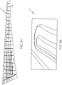
FIG. 3B is a perspective view of a beaded portion of the wing ofFIG. 3A ; -
FIG. 4 is a perspective view of a portion of the composite structure ofFIG. 1 ; -
FIG. 5A is a flowchart of a method for manufacturing the composite structure ofFIG. 1 ; -
FIG. 5B is a flowchart of a portion of the method ofFIG. 5A ; -
FIG. 5C is a flowchart of a portion of the method ofFIG. 5A ; -
FIG. 6 is a perspective view of a composite structure; -
FIG. 7 is a block diagram of aircraft production and service methodology; and -
FIG. 8 is a schematic illustration of an aircraft. - In the following description, numerous specific details are set forth to provide a thorough understanding of the disclosed concepts, which may be practiced without some or all of these particulars. In other instances, details of known devices and/or processes have been omitted to avoid unnecessarily obscuring the disclosure. While some concepts will be described in conjunction with specific examples, it will be understood that these examples are not intended to be limiting.
- Unless otherwise indicated, the terms "first," "second," etc. are used herein merely as labels, and are not intended to impose ordinal, positional, or hierarchical requirements on the items to which these terms refer. Moreover, reference to, e.g., a "second" item does not require or preclude the existence of, e.g., a "first" or lower-numbered item, and/or, e.g., a "third" or higher-numbered item.
- Reference herein to "one or more examples" means that one or more feature, structure, or characteristic described in connection with the example is included in at least one implementation. The phrase "one or more examples" in various places in the specification may or may not be referring to the same example.
- As used herein, a system, apparatus, structure, article, element, component, or hardware "configured to" perform a specified function is indeed capable of performing the specified function without any alteration, rather than merely having potential to perform the specified function after further modification. In other words, the system, apparatus, structure, article, element, component, or hardware "configured to" perform a specified function is specifically selected, created, implemented, utilized, programmed, and/or designed for the purpose of performing the specified function. As used herein, "configured to" denotes existing characteristics of a system, apparatus, structure, article, element, component, or hardware which enable the system, apparatus, structure, article, element, component, or hardware to perform the specified function without further modification. For purposes of this disclosure, a system, apparatus, structure, article, element, component, or hardware described as being "configured to" perform a particular function may additionally or alternatively be described as being "adapted to" and/or as being "operative to" perform that function.
- Illustrative, non-exhaustive examples of the subject matter, disclosed herein, are provided below.
-
FIG. 1 illustrate a perspective view of acomposite structure 100 that includes afirst layer 110 and asecond layer 120. Thefirst layer 110 is connected to thesecond layer 120 to form alayered structure 105. While thecomposite structure 100 is shown inFIG. 1 as a skin panel of an aircraft wing, those skilled in the art will appreciate that the disclosedcomposite structures 100 may be used in various applications, including various non-aerospace applications. - In one or more examples, the
second layer 120 of thecomposite structure 100 includes a plurality ofbase portions 140 and a plurality of beadedportions 130. The plurality ofbase portions 140 may abut thefirst layer 110 within thelayered structure 105 of thecomposite structure 100. The plurality of beadedportions 130 may protrude from the plurality ofbase portions 140. Therefore, each beadedportion 130 of the plurality of beadedportions 130 defines an associatedchannel 135 between thefirst layer 110 and thesecond layer 120 such that thecomposite structure 100 includes a plurality ofchannels 135. - In one or more examples, at least one
system feature 300 may be disposed in at least onechannel 135 of the plurality ofchannels 135. The system feature 300 may be, for example, awire 310, aconduit 320, a cable, a tube, optical fiber, or the like. Various other system features 300 may be received within the plurality ofchannels 135 without departing from the scope of the present disclosure. - In one or more examples, the
second layer 120 of thecomposite structure 100 may be formed from or may include a composite material. The composite material of thesecond layer 120 may include a reinforcement material encapsulated in a polymeric matrix material. As a specific, non-limiting example, the reinforcement material may be (or may include) carbon fibers, glass fibers or the like, while the polymeric matrix material may be (or may include) thermoset (e.g., epoxy) resin. The use of various thermoplastic resins, such as a polyaryletherketone, is also contemplated. - In one or more examples, the
layered structure 105 of thecomposite structure 100 defines one ormore access openings 150. In one variation, the access opening 150 extends through both thefirst layer 110 and thesecond layer 120. In another variation, the access opening 150 extends through only thefirst layer 110 of thelayered structure 105. In yet another variation, the access opening 150 extends through only thesecond layer 120 of thelayered structure 105. Therefore, anaccess opening 150 may be located in abeaded portion 130 of the plurality of beaded portions 130 (FIG. 6 ), on abase portion 140 of the plurality ofbase portions 140, or thecomposite structure 100 includes more than one access opening 150 wherein at least one access opening 150 is located in abeaded portion 130 and at least one access opening 150 is located on abase portion 140. - The at least one
access opening 150, illustrated inFIG. 6 , allows for access to abeaded portion 130 of the plurality of beadedportions 130 for maintenance. One or more system features 300 may be located in abeaded portion 130 of the plurality of beadedportions 130. Theaccess opening 150 allows for the one or more system features 300 to pass outside of the beadedportion 130. - As shown in
FIG. 1 , in one or more examples, thecomposite structure 100 may further include an access panel 151 (FIG. 1 ) sealing at least oneaccess opening 150. Theaccess panel 151 can be fluid-tight such that is keeps fluid from passing through the associated access opening 150. The access panel 151 (fuel dam) is configured to be easily accessible for inspection and repair from outside anaircraft wing 170, thus reducing the need to enter a confined space. - In one or more examples, the
first layer 110 of thecomposite structure 100 is free (or substantially free) of beadedportions 130. Alternatively, while not shown in the drawings, thefirst layer 110 may include a plurality of beadedportions 130 and a plurality ofbase portions 140, similar to thesecond layer 120. - In one or more examples, the
first layer 110 of thecomposite structure 100 may be formed from or may include a composite material. The composite material of thefirst layer 110 may include a reinforcement material encapsulated in a polymeric matrix material. As a specific, non-limiting example, the reinforcement material may be (or may include) carbon fibers, glass fibers or the like, while the polymeric matrix material may be (or may include) thermoset (e.g., epoxy) resin. The use of various thermoplastic resins, such as a polyaryletherketone, is also contemplated. - As best shown in
FIGs. 2A and2B , in one or more examples, thefirst layer 110 may define anaccess opening 150 providing access to the channel 135 (FIG. 1 ) between thefirst layer 110 and thesecond layer 120. Those skilled in the art will appreciate that thecomposite structure 100 may include more than one access opening 150 providing access to the plurality of channels 135 (FIG. 1 ). -
FIG. 2A andFIG. 2B illustrate two examples of the beadedportions 130 of the plurality of beadedportions 130. Specifically,FIG. 2A illustrates abeaded portion 130 that is hat-shaped or substantially hat-shaped in cross-section, whileFIG. 2B illustrates abeaded portion 130 having a rounded or substantially rounded shape in cross-section. - As shown in
FIG. 2A , each beadedportion 130 of the plurality of beadedportions 130 may includeopposed sidewall portions 132 and acap portion 134 extending between thesidewall portions 132. In one or more examples, the plurality ofbase portions 140 have a nominal first cross-sectional thickness T1, thesidewall portions 132 have a nominal second cross-sectional thickness T2, thecap portion 134 has a nominal third cross-sectional thickness T3. In one or more examples, the nominal third cross-sectional thickness T3 is greater or substantially greater (e.g., at least 5 percent greater, such as at least 20 percent greater) than the nominal first cross-sectional thickness T1 and greater or substantially greater (e.g., at least 5 percent greater, such as at least 20 percent greater) than the nominal second cross-sectional thickness T2. In one or more examples, the nominal first cross-sectional thickness T1 is the same (or substantially the same) as the nominal second cross-sectional thickness T2. In one or more examples, the nominal first cross-sectional thickness T1, the nominal second cross-sectional thickness T2, and the nominal third cross-sectional thickness T3 are the same (or substantially the same). - As illustrated in
FIG. 2A , thefirst layer 110 has a nominal fourth cross-sectional thickness T4 proximate eachbase portion 140 of the plurality ofbase portions 140 of thesecond layer 120. Thefirst layer 110 further has a nominal fifth cross-sectional thickness T5 below eachbeaded portion 130 of the plurality of beadedportions 130. In one or more examples, the nominal fifth cross-sectional thickness T5 is the same (or substantially the same) as a sum of the first cross-sectional thickness T1 and the nominal fourth cross-sectional thickness T4. The nominal fifth cross-sectional thickness T5 is greater than the nominal fourth cross-sectional thickness T4 such that thesecond layer 120 is configured to self-nest with thefirst layer 110. In one or more examples, the nominal fifth cross-sectional thickness T5 is the same (or substantially the same) as the nominal third cross-sectional thickness T3. - Referring to
FIG. 2B , when one or morebeaded portions 130 of the plurality of beadedportions 130 has a rounded shape in cross-section, therounded beaded portion 130 may have a nominal width W1 and a nominal height H1. In one or more examples, a ratio of the nominal height H1 to the nominal width W1 may be less than 1. In other examples, a ratio of the nominal height H1 to the nominal width W1 is 1 (or approximately 1). In yet other examples, as illustrated inFIG. 2B , each beadedportion 130 of the plurality of beadedportions 130 is elongated such that it has an oval or substantially oval shape. - In one or more examples, as illustrated in
FIG. 3B , each beadedportion 130 of the plurality of beadedportions 130 includes atapered end cap 138 that transitions to abase portion 140 of the plurality ofbase portions 140. Thetapered end cap 138 has a flared geometry to transition from a hat shape or round shape beadedportion 130 to a planar or substantially planar portion of thesecond layer 120. In one or more examples, thetapered end cap 138 is integrated with thesecond layer 120 such that they are a single monolithic body. In one or more examples, thetapered end cap 138 is formed separately, such as punch formed, and then co-cured with thesecond layer 120 for integration. - As illustrated in
FIG. 2A and2B , thelayered structure 105 defines atransition region 136 where thesecond layer 120 transitions from abase portion 140 of the plurality ofbase portions 140 to abeaded portion 130 of the plurality of beadedportions 130. In one or more examples, afiller material 155 is disposed in thetransition region 136 between thefirst layer 110 and thesecond layer 120. Thefiller material 155 defines a fillet region within thetransition region 136. In one or more examples, thefiller material 155 is co-cured with at least one of thefirst layer 110 or thesecond layer 120 of thelayered structure 105. -
FIG. 4 illustrates a portion of an example of thesecond layer 120. In one or more examples, thesecond layer 120 includes at least oneintegral flange 128. Theintegral flange 128 is configured to align with aspar 175. In one or more examples, theintegral flange 128 is parallel (or substantially parallel) with aspar 175. - In one or more examples, the
first layer 110 and thesecond layer 120 of the disclosedcomposite structure 100 may be co-cured, thereby yielding thelayered structure 105 of thecomposite structure 100. Alternatively, thelayered structure 105 of the disclosedcomposite structure 100 may include an adhesive (not shown) disposed between thefirst layer 110 and thesecond layer 120. The adhesive may be positioned between a first major surface 112 (FIG. 2B ) of thefirst layer 110 and a second major surface 122 (FIG. 2B ) of thesecond layer 120 along thebase portions 140 of thesecond layer 120. - As illustrated in
FIG. 3A , disclosed is anaircraft wing 170. Theaircraft wing 170 may be tapered or substantially tapered in shape. In one or more examples, theaircraft wing 170 includes alower skin panel 190 and anupper skin panel 180. At least one of theupper skin panel 180 and thelower skin panel 190 includes the disclosedcomposite structure 100 comprised of afirst layer 110 and asecond layer 120. Thesecond layer 120 is connected to thefirst layer 110 to form alayered structure 105. In one or more examples, thesecond layer 120 includes a plurality ofbase portions 140 abutting thefirst layer 110. Thesecond layer 120 further includes a plurality of beadedportions 130 protruding from the plurality ofbase portions 140. In one or more examples, each beadedportion 130 of the plurality of beadedportions 130 defines achannel 135 between thefirst layer 110 and thesecond layer 120. The plurality of beadedportions 130 may include eight (or approximately eight) beadedportions 130. In one or more examples, at least onesystem feature 300 is disposed in the plurality ofchannels 135. The system feature 300 is one of awire 310, aconduit 320, or any other system feature 300 provided therein. - In one or more examples, as illustrated in
FIG. 1 , both theupper skin panel 180 and thelower skin panel 190 have a layeredstructure 105 including afirst layer 110 and asecond layer 120. Thesecond layer 120 is connected to thefirst layer 110 to form thelayered structure 105. In one or more examples, thesecond layer 120 includes a plurality ofbase portions 140 abutting thefirst layer 110. Thesecond layer 120 further includes a plurality of beadedportions 130 protruding from the plurality ofbase portions 140. In one or more examples, each beadedportion 130 of the plurality of beadedportions 130 defines achannel 135 between thefirst layer 110 and thesecond layer 120. The plurality of beadedportions 130 may include 8 (or approximately 8) of eachbeaded portion 130. In one or more examples, at least onesystem feature 300 is disposed in the plurality ofchannels 135. The system feature 300 is one of awire 310, aconduit 320, or any other system feature 300 provided therein. - In one or more examples, the
aircraft wing 170 includes a fluid-tight volume 177 defined, at least partially, by theupper skin panel 180, thelower skin panel 190, and thespar 175. The plurality ofchannels 135 are fluidly isolated from the fluid-tight volume 177 such that no liquid contaminates any system feature 300 disposed within achannel 135 of the plurality ofchannels 135. In one or more examples, theaircraft wing 170 includes at least onerib 173 disposed between theupper skin panel 180 and thelower skin panel 190. The at least onerib 173 defines a fluid-tight volume 177 with theupper skin panel 180, thelower skin panel 190, and thespar 175. In one or more examples, theaircraft wing 170 includes more than onerib 173 that define more than one fluid-tight volume 177. In one or more examples, at least one fluid-tight volume 177 is a fuel tank. -
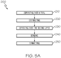
FIG. 5A illustrates a flow diagram of amethod 200 for manufacturing acomposite structure 100. Themethod 200 includes depositing 210 composite material over a tool to form asecond layer 120. Thesecond layer 120 includes a plurality of beadedportions 130 and a plurality ofbase portions 140. In one or more examples, the plurality of beadedportions 130 define a plurality ofchannels 135. - In one or more examples, the
method 200 includes distributing 220 a plurality of mandrels over thesecond layer 120 to define channels in the plurality of beadedportions 130. In one or more examples, the distributing 220 the plurality of mandrels includes distributing 220 a plurality of dissolvable mandrels. In one or more examples, the plurality of dissolvable mandrels include a ceramic material. The ceramic material is dissolvable in water. In one or more examples, the plurality of beadedportions 130 define a plurality ofchannels 135. - In one or more examples, the
method 200 includes depositing 230 composite material over thesecond layer 120 and the plurality of mandrels to form afirst layer 110. Thefirst layer 110 is free (or substantially free) of beadedportions 130. - In one or more examples, the
method 200 includesbonding 240 thefirst layer 110 to thesecond layer 120. Thebonding 240 is achieved by curing 253 one or more of thefirst layer 110 and thesecond layer 120 simultaneously or sequentially. Curing 253 may be performed in an autoclave. In one or more examples, thebonding 240 includes curing 253 thefirst layer 110. In one or more examples, thebonding 240 includes curing 253 an adhesive disposed between thefirst layer 110 and thesecond layer 120. In one or more examples, thebonding 240 includes curing 253 thesecond layer 120. - In one or more examples, the
method 200 for manufacturing acomposite structure 100 includes connecting 250 afirst layer 110 to asecond layer 120 to form alayered structure 105. Thesecond layer 120 of thelayered structure 105 includes a plurality ofbase portions 140 abutting thefirst layer 110 and a plurality of beadedportions 130 protruding from the plurality ofbase portions 140. In one or more examples, each beadedportion 130 of the plurality of beadedportions 130 defines achannel 135 between thefirst layer 110 and thesecond layer 120. - In one or more examples, the connecting 250 includes co-curing 259 the
first layer 110 and thesecond layer 120 to form alayered structure 105. -
FIG. 5B illustrates one example of the connecting 250. In one or more examples, the connecting 250 includes separately curing 253 thefirst layer 110 and thesecond layer 120 to yield a cured first layer 110' and a cured second layer 120'. The connecting 250 further includesbonding 255 the cured first layer 110' to the cured second layer 120' to form alayered structure 105. -
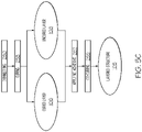
FIG. 5C illustrates another example of the connecting 250. In one or more examples, the connecting 250 includes curing one of thefirst layer 110 and thesecond layer 120 to yield a curedlayer 106 and anuncured layer 108. The connecting 250 further includes applying 257 an adhesive between the curedlayer 106 and theuncured layer 108. The connecting 250 further includes co-curing 259 the adhesive and theuncured layer 108 to form alayered structure 105. - Examples of the subject matter disclosed herein may be described in the context of aircraft manufacturing and
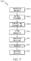
service method 1100 as shown inFIG. 7 andaircraft 1102 as shown inFIG. 8 . During pre-production,illustrative method 1100 may include specification and design (block 1104) ofaircraft 1102 and material procurement (block 1106). During production, component and subassembly manufacturing (block 1108) and system integration (block 1110) ofaircraft 1102 may take place. Thereafter,aircraft 1102 may go through certification and delivery (block 1112) to be placed in service (block 1114). While in service,aircraft 1102 may be scheduled for routine maintenance and service (block 1116). Routine maintenance and service may include modification, reconfiguration, refurbishment, etc. of one or more systems ofaircraft 1102. - Each of the processes of
illustrative method 1100 may be performed or carried out by a system integrator, a third party, and/or an operator (e.g., a customer). For the purposes of this description, a system integrator may include, without limitation, any number of aircraft manufacturers and major-system subcontractors; a third party may include, without limitation, any number of vendors, subcontractors, and suppliers; and an operator may be an airline, leasing company, military entity, service organization, and so on. - As shown in
FIG. 8 ,aircraft 1102 produced byillustrative method 1100 may includeairframe 1118 with a plurality of high-level systems 1120 and interior 1122. Examples of high-level systems 1120 include one or more ofpropulsion system 1124,electrical system 1126,hydraulic system 1128, andenvironmental system 1130. Any number of other systems may be included. Although an aerospace example is shown, the principles disclosed herein may be applied to other industries, such as the automotive industry. Accordingly, in addition toaircraft 1102, the principles disclosed herein may apply to other vehicles, e.g., land vehicles, marine vehicles, space vehicles, etc. - Apparatus(es) and method(s) shown or described herein may be employed during any one or more of the stages of the manufacturing and
service method 1100. For example, components or subassemblies corresponding to component and subassembly manufacturing (block 1108) may be fabricated or manufactured in a manner similar to components or subassemblies produced whileaircraft 1102 is in service (block 1114). Also, one or more examples of the apparatus(es), method(s), or combination thereof may be utilized during production stages (block 1108 and block 1110), for example, by expediting (or substantially expediting) assembly of or reducing the cost ofaircraft 1102. Similarly, one or more examples of the apparatus or method realizations, or a combination thereof, may be utilized, for example and without limitation, whileaircraft 1102 is in service (block 1114) and/or during maintenance and service (block 1116). - Further illustrative and non-exclusive examples according to the disclosure are described in the following paragraphs:
A composite structure (100) comprises: a first layer (110); and a second layer (120) connected to the first layer (110) to form a layered structure (105), the second layer (120) comprising: a plurality of base portions (140) abutting the first layer (110); and a plurality of beaded portions (130) protruding from the plurality of base portions (140), each beaded portion (130) of the plurality of beaded portions (130) defining a channel (135) between the first layer (110) and the second layer (120). - Optionally, in the composite structure (100) of the preceding paragraph, the first layer (110) is free or substantially free of beaded portions (130).
- Optionally, in the composite structure (100) of either of the two preceding paragraphs, both the first layer (120) and the second layer (120) comprise a composite material.
- Optionally, in the composite structure (100) of any of the three preceding paragraphs, the composite material comprises reinforcement material encapsulated in a polymeric matrix material.
- Optionally, in the composite structure (100) of any of the four preceding paragraphs, the plurality of base portions (140) and the plurality of beaded portions (130) of the second layer (120) comprise a single monolithic body.
- Optionally, the composite structure (100) of any of the five preceding paragraphs,further comprises an adhesive disposed between the first layer (110) and the second layer (120).
- Optionally, in the composite structure (100) of any of the six preceding paragraphs,the adhesive is disposed between a first major surface (112) of the first layer (120) and a second major surface (122) of the second layer (120) along the base portions (140) of the second layer (120).
- Optionally, in the composite structure (100) of any of the seven preceding paragraphs,the first layer (110) defines an access opening (150) providing access to the channel (135) between the first layer (110) and the second layer (120).
- Optionally, in the composite structure (100) of any of the eight preceding paragraphs, each beaded portion (130) of the plurality of beaded portions (130) comprises opposed sidewall portions (132) and a cap portion (134) between the opposed sidewall portions (132).
- Optionally, in the composite structure (100) of any of the nine preceding paragraphs, wherein: the plurality of base portions (140) have a nominal first cross-sectional thickness (T1), the opposed sidewall portions (132) have a nominal second cross-sectional thickness (T2), the cap portion (134) has a nominal third cross-sectional thickness (T3), and the nominal third cross-sectional thickness (T3) is greater or substantially greater than the nominal first cross-sectional thickness (T1) and greater or substantially greater than the nominal second cross-sectional thickness (T2).
- Optionally, in the composite structure (100) of any of the ten preceding paragraphs,the nominal first cross-sectional thickness (T1) is the same or substantially the same as the nominal second cross-sectional thickness (T2).
- Optionally, in the composite structure (100) of any of the eleven preceding paragraphs, wherein: the plurality of base portions (140) have a nominal first cross-sectional thickness (T1), the opposed sidewall portions (132) have a nominal second cross-sectional thickness (T2), the cap portion (134) has a nominal third cross-sectional thickness (T3), and the nominal first cross-sectional thickness (T1), the nominal second cross-sectional thickness (T2), and the nominal third cross-sectional thickness (T3) are the same or substantially the same.
- Optionally, in the composite structure (100) of any of the twelve preceding paragraphs, wherein: the plurality of base portions (140) have a nominal first cross-sectional thickness (T1), the first layer (110) has a nominal fourth cross-sectional thickness (T4) at each base portion (140) of the plurality of base portions (140), the first layer (110) has a nominal fifth cross-sectional thickness (T5) at each beaded portion (130) of the plurality of beaded portions (130), and the nominal fifth cross-sectional thickness (T5) is the same or substantially the same as a sum of the nominal first cross-sectional thickness (T1) and the nominal fourth cross-sectional thickness (T4).
- Optionally, in the composite structure (100) of any of the thirteen preceding paragraphs, the layered structure (105) defines a transition region (136) where the second layer (120) transitions from a base portion (140) of the plurality of base portions (140) to a beaded portion (130) of the plurality of beaded portions (130), and wherein a filler material (155) is disposed in the transition region (136) between the first layer (110) and the second layer (120).
- Optionally, in the composite structure (100) of any of the fourteen preceding paragraphs, the layered structure (105) defines an access opening (150).
- Optionally, the composite structure (100) of any of the fifteen preceding paragraphs, comprises an access panel (151) sealing the access opening (150).
- Optionally, in the composite structure (100) of any of the sixteen preceding paragraphs, the second layer (120) comprises at least one integral flange (128).
- Optionally, in the composite structure (100) of any of the seventeen preceding paragraphs, each beaded portion (130) of the plurality of beaded portions (130) is hat-shaped.
- Optionally, in the composite structure (100) of any of the eighteen preceding paragraphs, wherein: each beaded portion (130) of the plurality of beaded portions (130) has a nominal width (W1), each beaded portion (130) of the plurality of beaded portions (130) has a nominal height (H1), and a ratio of (H1) to (W1) is less than 1.
- Optionally, in the composite structure (100) of any of the nineteen preceding paragraphs, each beaded portion (130) of the plurality of beaded portions (130) is elongated.
- Optionally, in the composite structure (100) of any of the twenty preceding paragraphs, each beaded portion (130) of the plurality of beaded portions (130) comprises a tapered end cap (138) that transitions to a base portion (140) of the plurality of base portions (140).
- An aircraft wing (170) comprises: an upper skin panel (180); and a lower skin panel (190), wherein at least one of the upper skin panel (180) and the lower skin panel (190) comprises the composite structure (100) of any of the twenty-one preceding paragraphs.
- An aircraft wing (170) comprises: an upper skin panel (180); and a lower skin panel (190), wherein at least one of the upper skin panel (180) and the lower skin panel (190) comprises: a first layer (110); and a second layer (120) connected to the first layer (110) to form a layered structure (105), the second layer (120) comprising: a plurality of base portions (140) abutting the first layer (110); and a plurality of beaded portions (130) protruding from the plurality of base portions (140), each beaded portion (130) of the plurality of beaded portions (130) defining an associated channel (135) of a plurality of channels (135) between the first layer (110) and the second layer (120).
- Optionally, the aircraft wing (170) of either of the two preceding paragraph comprises at least one spar (175) disposed between the upper skin panel (180) and the lower skin panel (190).
- Optionally, the aircraft wing (170) of any of the three preceding paragraphs comprises a fluid-tight volume (177) defined, at least partially, by: the upper skin panel (180), the lower skin panel (190), and the spar (175).
- Optionally, in the aircraft wing (170) of any of the four preceding paragraphs, the plurality of channels (135) are fluidly isolated from the fluid-tight volume (177).
- Optionally, in the aircraft wing (170) of any of the five preceding paragraphs, a system feature (300) is disposed in the plurality of channels (135).
- Optionally, in the aircraft wing (170) of any of the six preceding paragraphs, the system feature (300) is at least one of a wire (310) and a conduit (320).
- Optionally, the aircraft wing (170) of any of the seven preceding paragraphs, comprises at least one rib (173) disposed between the upper skin panel (180) and the lower skin panel (190).
- A method (200) for manufacturing a composite structure (100), the method (200) comprises: depositing (210) composite material over a tool to form a second layer (120), the second layer (120) having a plurality of beaded portions (130) and a plurality of base portions (140); distributing (220) a plurality of mandrels over the second layer (120) to define channels in the plurality of beaded portions (130); depositing (230) composite material over the second layer (120) and the plurality of mandrels to form a first layer (110); and bonding (240) the first layer (110) to the second layer (120).
- Optionally, in the method (200) of the preceding paragraph, the distributing (220) the plurality of mandrels comprises distributing (220) a plurality of dissolvable mandrels.
- Optionally, in the method (200) of either of the two preceding paragraphs, the plurality of dissolvable mandrels comprise a ceramic material.
- Optionally, in the method (200) of any one of the three preceding paragraphs, wherein the bonding (240) comprises curing the first layer (110).
- Optionally, in the method (200) of any of the fur preceding paragraphs, the bonding (240) comprises curing an adhesive disposed between the first layer (110) and the second layer (120).
- Optionally, in the method (200) of any of the five preceding paragraphs, the bonding (240) comprises curing the second layer (120).
- A method (200) for manufacturing a composite structure (100), the method (200) comprises: connecting (250) a first layer (110) to a second layer (120) to form a layered structure (105), the second layer (120) comprising: a plurality of base portions (140) abutting the first layer (110); and a plurality of beaded portions (130) protruding from the plurality of base portions (140), each beaded portion (130) of the plurality of beaded portions (130) defining a channel (135) between the first layer (110) and the second layer (120).
- Optionally, in the method (200) of the preceding paragraph, the connecting (250) comprises co-curing the first layer (110) and the second layer (120).
- Optionally, in the method (200) of either of the two preceding paragraphs, the connecting (250) comprises: separately curing the first layer (110) and the second layer (120) to yield a cured first layer (110') and a cured second layer (120'); and bonding the cured first layer (110') to the cured second layer (120').
- Optionally, in the method (200) of any of the three preceding paragraphs, the connecting (250) comprises: curing one of the first layer (110) and the second layer (120) to yield a cured layer (106) and an uncured layer (108); applying an adhesive between the cured layer (106) and the uncured layer (108); and co-curing the adhesive and the uncured layer (108).
- Different examples of the apparatus(es) and method(s) disclosed herein include a variety of components, features, and functionalities. It should be understood that the various examples of the apparatus(es) and method(s), disclosed herein, may include any of the components, features, and functionalities of any of the other examples of the apparatus(es) and method(s) disclosed herein in any combination.
- Although various examples of the disclosed beaded composite structures and methods for manufacturing beaded composite structures have been shown and described, modifications may occur to those skilled in the art upon reading the specification. The present application includes such modifications and is limited only by the scope of the claims.
- Therefore, it is to be understood that the subject matter, disclosed herein, is not to be limited to the specific examples illustrated and that modifications and other examples are intended to be included within the scope of the appended claims. Moreover, although the foregoing description and the associated drawings describe examples of the subject matter, disclosed herein, in the context of certain illustrative combinations of elements and/or functions, it should be appreciated that different combinations of elements and/or functions may be provided by alternative examples without departing from the scope of the appended claims. Accordingly, parenthetical reference numerals in the appended claims are presented for illustrative purposes only and are not intended to limit the scope of the claimed subject matter to the specific examples provided herein.
Claims (15)
- A composite structure (100) comprising:a first layer (110); anda second layer (120) connected to the first layer (110) to form a layered structure (105), the second layer (120) comprising:a plurality of base portions (140) abutting the first layer (110); anda plurality of beaded portions (130) protruding from the plurality of base portions (140), each beaded portion (130) of the plurality of beaded portions (130) defining a channel (135) between the first layer (110) and the second layer (120).
- The composite structure (100) of Claim 1 wherein the first layer (110) is substantially free of beaded portions (130).
- The composite structure (100) of Claim 1 or 2 wherein the first layer (110) defines an access opening (150) providing access to the channel (135) between the first layer (110) and the second layer (120).
- The composite structure (100) of one of Claims 1-3 wherein each beaded portion (130) of the plurality of beaded portions (130) comprises opposed sidewall portions (132) and a cap portion (134) between the opposed sidewall portions (132).
- The composite structure (100) of Claim 4 wherein:the plurality of base portions (140) have a nominal first cross-sectional thickness (T1),the opposed sidewall portions (132) have a nominal second cross-sectional thickness (T2),the cap portion (134) has a nominal third cross-sectional thickness (T3), andthe nominal third cross-sectional thickness (T3) is substantially greater than the nominal first cross-sectional thickness (T1) and substantially greater than the nominal second cross-sectional thickness (T2).
- The composite structure (100) of Claim 5 wherein the nominal first cross-sectional thickness (T1) is substantially the same as the nominal second cross-sectional thickness (T2).
- The composite structure (100) of Claim 4 wherein:the plurality of base portions (140) have a nominal first cross-sectional thickness (T1),the opposed sidewall portions (132) have a nominal second cross-sectional thickness (T2),the cap portion (134) has a nominal third cross-sectional thickness (T3), andthe nominal first cross-sectional thickness (T1), the nominal second cross-sectional thickness (T2), and the nominal third cross-sectional thickness (T3) are substantially the same.
- The composite structure (100) of one of Claims 4-7 wherein:the plurality of base portions (140) have a nominal first cross-sectional thickness (T1),the first layer (110) has a nominal fourth cross-sectional thickness (T4) at each base portion (140) of the plurality of base portions (140),the first layer (110) has a nominal fifth cross-sectional thickness (T5) at each beaded portion (130) of the plurality of beaded portions (130), andthe nominal fifth cross-sectional thickness (T5) is substantially the same as a sum of the nominal first cross-sectional thickness (T1) and the nominal fourth cross-sectional thickness (T4).
- The composite structure (100) of one of Claims 1-8 wherein the layered structure (105) defines a transition region (136) where the second layer (120) transitions from a base portion (140) of the plurality of base portions (140) to a beaded portion (130) of the plurality of beaded portions (130), and wherein a filler material (155) is disposed in the transition region (136) between the first layer (110) and the second layer (120).
- The composite structure (100) of one of Claims 1-9 wherein:each beaded portion (130) of the plurality of beaded portions (130) has a nominal width (W1),each beaded portion (130) of the plurality of beaded portions (130) has a nominal height (H1), anda ratio of (H1) to (W1) is less than 1.
- An aircraft wing (170) comprises:an upper skin panel (180); anda lower skin panel (190), wherein at least one of the upper skin panel (180) and the lower skin panel (190) comprises the composite structure (100) of any one of Claims 1-10.
- An aircraft comprising the aircraft wing (170) of claim 11.
- A method (200) for manufacturing a composite structure (100), the method (200) comprising:depositing (210) composite material over a tool to form a second layer (120), the second layer (120) having a plurality of beaded portions (130) and a plurality of base portions (140);distributing (220) a plurality of mandrels over the second layer (120) to define channels (135) in the plurality of beaded portions (130);depositing (230) composite material over the second layer (120) and the plurality of mandrels to form a first layer (110); andbonding (240) the first layer (110) to the second layer (120).
- The method (200) of Claim 13 wherein:the distributing (220) the plurality of mandrels comprises distributing (220) a plurality of dissolvable mandrels; and, optionally,the bonding (240) comprises curing the first layer (110).
- The method (200) of either of Claims 13 or 14 wherein the bonding (240) comprises:curing an adhesive disposed between the first layer (110) and the second layer (120); and/orcuring the second layer (120).
Applications Claiming Priority (1)
| Application Number | Priority Date | Filing Date | Title |
|---|---|---|---|
| US202163139509P | 2021-01-20 | 2021-01-20 |
Publications (1)
| Publication Number | Publication Date |
|---|---|
| EP4032696A1 true EP4032696A1 (en) | 2022-07-27 |
Family
ID=80218588
Family Applications (1)
| Application Number | Title | Priority Date | Filing Date |
|---|---|---|---|
| EP22150422.8A Pending EP4032696A1 (en) | 2021-01-20 | 2022-01-06 | Beaded composite structures and methods for manufacturing beaded composite structures |
Country Status (4)
| Country | Link |
|---|---|
| US (2) | US12252245B2 (en) |
| EP (1) | EP4032696A1 (en) |
| JP (1) | JP2022112010A (en) |
| CN (1) | CN114802701A (en) |
Families Citing this family (1)
| Publication number | Priority date | Publication date | Assignee | Title |
|---|---|---|---|---|
| US12176697B2 (en) * | 2023-03-24 | 2024-12-24 | Archer Aviation Inc. | Systems and methods for routing electrical wiring through an aircraft structure |
Citations (4)
| Publication number | Priority date | Publication date | Assignee | Title |
|---|---|---|---|---|
| US20050230552A1 (en) * | 2004-04-20 | 2005-10-20 | The Boeing Company | Co-cured stringers and associated mandrel and fabrication method |
| WO2011061513A2 (en) * | 2009-11-20 | 2011-05-26 | Gkn Aerospace Services Limited | Dual-skin structures |
| EP2676787A1 (en) * | 2012-06-24 | 2013-12-25 | The Boeing Company | Composite hat stiffener, composite hat-stiffened pressure webs, and methods of making the same |
| EP3235629A1 (en) * | 2014-12-15 | 2017-10-25 | Mitsubishi Heavy Industries, Ltd. | Composite structure and method for molding composite structure |
Family Cites Families (31)
| Publication number | Priority date | Publication date | Assignee | Title |
|---|---|---|---|---|
| US3029910A (en) | 1958-11-07 | 1962-04-17 | Gen Dynamics Corp | Composite structural unit |
| FR2586080B1 (en) * | 1985-08-12 | 1987-11-27 | Centre Nat Etd Spatiales | THERMAL PROTECTION ELEMENT FOR A MACHINE SUBJECT TO IMPORTANT HEATING |
| US5893534A (en) | 1995-12-22 | 1999-04-13 | The Boeing Company | Structural apparatus and design to prevent oil can movement of webs in aircraft pressure bulkheads |
| DE19722037A1 (en) | 1997-05-27 | 1998-12-03 | Hecralmat Fa | Heat shield with sound insulation |
| DE19849366A1 (en) | 1998-10-20 | 2000-04-27 | J & S Gmbh Werkzeugbau Stanz U | Sandwich shield plate consists of non-metallic intermediate layer between two metal sheets, and structural elements in one sheet |
| US6983912B2 (en) | 2002-04-30 | 2006-01-10 | The Boeing Company | Hybrid exhaust heat shield for pylon mounted gas turbine engines |
| CA2414160A1 (en) | 2002-12-12 | 2004-06-12 | Van-Rob Stampings Inc. | Multi-layered embossed heat shield for a vehicle exhaust system and other heat insulation applications |
| FR2867507B1 (en) | 2004-03-15 | 2006-06-23 | Snecma Moteurs | POSITIONING PONTET AND ITS USE AT THE TUYERE SUPPORT CHANNEL OF A TURBOPROPULSEUR |
| US7533794B2 (en) | 2004-03-31 | 2009-05-19 | The Boring Company | Superplastic forming and diffusion bonding of fine grain titanium |
| US7850058B2 (en) | 2004-03-31 | 2010-12-14 | The Boeing Company | Superplastic forming of titanium assemblies |
| GB0611875D0 (en) * | 2006-06-15 | 2006-07-26 | Airbus Uk Ltd | A stringer for an aircraft wing and a method of forming thereof |
| US7861969B2 (en) | 2007-05-24 | 2011-01-04 | The Boeing Company | Shaped composite stringers and methods of making |
| US20080302912A1 (en) * | 2007-06-08 | 2008-12-11 | The Boeing Company | Bladderless Mold Line Conformal Hat Stringer |
| EP2019193A1 (en) | 2007-07-26 | 2009-01-28 | Reinz-Dichtungs-Gmbh | Heat shield |
| FR2921342B1 (en) | 2007-09-20 | 2010-03-12 | Airbus France | LOWER REAR AERODYNAMIC FAIRING FOR AN AIRCRAFT ENGINE CLAMPING DEVICE |
| US7927686B2 (en) | 2007-10-11 | 2011-04-19 | The Boeing Company | Composite heat shield |
| DE102008006401A1 (en) | 2008-01-28 | 2009-07-30 | Benteler Automobiltechnik Gmbh | Method for producing an exhaust silencer and exhaust silencer |
| US8348196B2 (en) * | 2010-08-17 | 2013-01-08 | The Boeing Company | Multi-spar port box joint |
| FR2977567B1 (en) | 2011-07-07 | 2014-12-26 | Airbus Operations Sas | METHOD FOR COOLING A THERMAL PROTECTION FLOOR OF AERODYNAMIC REAR FITTING OF A FITTING MAT OF A PROPELLANT AIRCRAFT ASSEMBLY |
| FR2981636B1 (en) | 2011-10-19 | 2013-12-27 | Airbus Operations Sas | AERODYNAMIC REAR FITTING FOR AN AIRCRAFT ENGINE HANDLING DEVICE, COMPRISING A THERMAL SHIELD CAPABLE OF FREE DILATION |
| US9156559B2 (en) * | 2011-10-19 | 2015-10-13 | The Boeing Company | Segmented aircraft wing having solar arrays |
| US9783285B2 (en) | 2012-04-09 | 2017-10-10 | The Boeing Company | Thermal insulation support |
| US8844796B1 (en) | 2013-03-05 | 2014-09-30 | The Boeing Company | Superplastically formed ultrasonically welded metallic structure |
| CA2901903C (en) | 2013-03-06 | 2021-03-23 | Kevin Shephard | Aft pylon fairing for aircraft |
| US9399509B2 (en) * | 2014-04-10 | 2016-07-26 | The Boeing Company | Vent stringer fitting |
| US20160129985A1 (en) * | 2014-11-08 | 2016-05-12 | Airbus Group India Private Limited | Aircraft structure having cables located in stringers |
| US9993925B2 (en) * | 2015-08-25 | 2018-06-12 | The Boeing Company | End effector apparatus and methods for handling composite structures |
| US10427778B2 (en) | 2016-03-14 | 2019-10-01 | The Boeing Company | Heat shield assembly and method |
| CN109562578B (en) * | 2016-09-29 | 2020-12-08 | 株式会社斯巴鲁 | Composite structure and method of manufacturing composite structure |
| US20190283856A1 (en) * | 2018-03-13 | 2019-09-19 | Spirit Aerosystems, Inc. | Panel structure of optimally constructed and subsequently integrated components and method of making same |
| US10807699B1 (en) * | 2019-06-10 | 2020-10-20 | Spirit Aerosystems, Inc. | Composite stringer end cap |
-
2021
- 2021-12-08 US US17/545,056 patent/US12252245B2/en active Active
- 2021-12-29 CN CN202111644241.6A patent/CN114802701A/en active Pending
-
2022
- 2022-01-06 EP EP22150422.8A patent/EP4032696A1/en active Pending
- 2022-01-18 JP JP2022005422A patent/JP2022112010A/en active Pending
-
2025
- 2025-02-12 US US19/051,433 patent/US20250178716A1/en active Pending
Patent Citations (4)
| Publication number | Priority date | Publication date | Assignee | Title |
|---|---|---|---|---|
| US20050230552A1 (en) * | 2004-04-20 | 2005-10-20 | The Boeing Company | Co-cured stringers and associated mandrel and fabrication method |
| WO2011061513A2 (en) * | 2009-11-20 | 2011-05-26 | Gkn Aerospace Services Limited | Dual-skin structures |
| EP2676787A1 (en) * | 2012-06-24 | 2013-12-25 | The Boeing Company | Composite hat stiffener, composite hat-stiffened pressure webs, and methods of making the same |
| EP3235629A1 (en) * | 2014-12-15 | 2017-10-25 | Mitsubishi Heavy Industries, Ltd. | Composite structure and method for molding composite structure |
Also Published As
| Publication number | Publication date |
|---|---|
| JP2022112010A (en) | 2022-08-01 |
| US20220227475A1 (en) | 2022-07-21 |
| CN114802701A (en) | 2022-07-29 |
| US20250178716A1 (en) | 2025-06-05 |
| US12252245B2 (en) | 2025-03-18 |
Similar Documents
| Publication | Publication Date | Title |
|---|---|---|
| CN103979099B (en) | Method and system of making composite structures having gap fillers with chopped fiber material | |
| US8651419B2 (en) | Flexible truss frame and method of making the same | |
| US9724891B2 (en) | Bead-stiffened composite parts | |
| US10442154B2 (en) | Composite structure and method for barely visible impact damage detection | |
| US10647406B2 (en) | Closed-angle composite airfoil spar and method of fabricating the same | |
| AU2015200679B2 (en) | Folded composite filler | |
| US20140042271A1 (en) | Monolithic Composite Structures for Vehicles | |
| US20170087745A1 (en) | Fiber-reinforced Thermoplastic Composite Structure and Method for Making the Same | |
| US20250178716A1 (en) | Beaded composite structures and methods for manufacturing beaded composite structures | |
| US11426971B2 (en) | Composite structure and method for barely visible impact damage detection | |
| EP4052891B1 (en) | Structures and methods for repairing composite members | |
| US20190061310A1 (en) | Composite structure and method for barely visible impact damage detection | |
| CN111114743B (en) | Composite structure, aircraft and method for virtually invisible impact damage detection | |
| EP2848518B1 (en) | Carbon fiber reinforced polymer cargo beam with integrated cargo stanchions and c-splices | |
| US12296546B2 (en) | Apparatus and method for manufacturing a composite part to provide smooth join surfaces of the composite part | |
| US20260091572A1 (en) | Reinforcement film for a sandwich core and method of making a reinforced sandwich core | |
| US11377851B2 (en) | Stringer and associated composite structure and method for reinforcing a base structure |
Legal Events
| Date | Code | Title | Description |
|---|---|---|---|
| PUAI | Public reference made under article 153(3) epc to a published international application that has entered the european phase |
Free format text: ORIGINAL CODE: 0009012 |
|
| STAA | Information on the status of an ep patent application or granted ep patent |
Free format text: STATUS: THE APPLICATION HAS BEEN PUBLISHED |
|
| AK | Designated contracting states |
Kind code of ref document: A1 Designated state(s): AL AT BE BG CH CY CZ DE DK EE ES FI FR GB GR HR HU IE IS IT LI LT LU LV MC MK MT NL NO PL PT RO RS SE SI SK SM TR |
|
| STAA | Information on the status of an ep patent application or granted ep patent |
Free format text: STATUS: REQUEST FOR EXAMINATION WAS MADE |
|
| 17P | Request for examination filed |
Effective date: 20230126 |
|
| RBV | Designated contracting states (corrected) |
Designated state(s): AL AT BE BG CH CY CZ DE DK EE ES FI FR GB GR HR HU IE IS IT LI LT LU LV MC MK MT NL NO PL PT RO RS SE SI SK SM TR |
|
| RAP3 | Party data changed (applicant data changed or rights of an application transferred) |
Owner name: THE BOEING COMPANY |