EP4032582A1 - Bioelectrode and cardiac pacemaker - Google Patents
Bioelectrode and cardiac pacemaker Download PDFInfo
- Publication number
- EP4032582A1 EP4032582A1 EP19950944.9A EP19950944A EP4032582A1 EP 4032582 A1 EP4032582 A1 EP 4032582A1 EP 19950944 A EP19950944 A EP 19950944A EP 4032582 A1 EP4032582 A1 EP 4032582A1
- Authority
- EP
- European Patent Office
- Prior art keywords
- conductive fabric
- thin metallic
- metallic wire
- biological electrode
- conductor
- Prior art date
- Legal status (The legal status is an assumption and is not a legal conclusion. Google has not performed a legal analysis and makes no representation as to the accuracy of the status listed.)
- Granted
Links
Images




Classifications
-
- A—HUMAN NECESSITIES
- A61—MEDICAL OR VETERINARY SCIENCE; HYGIENE
- A61N—ELECTROTHERAPY; MAGNETOTHERAPY; RADIATION THERAPY; ULTRASOUND THERAPY
- A61N1/00—Electrotherapy; Circuits therefor
- A61N1/02—Details
- A61N1/04—Electrodes
- A61N1/05—Electrodes for implantation or insertion into the body, e.g. heart electrode
- A61N1/0526—Head electrodes
- A61N1/0541—Cochlear electrodes
-
- A—HUMAN NECESSITIES
- A61—MEDICAL OR VETERINARY SCIENCE; HYGIENE
- A61N—ELECTROTHERAPY; MAGNETOTHERAPY; RADIATION THERAPY; ULTRASOUND THERAPY
- A61N1/00—Electrotherapy; Circuits therefor
- A61N1/18—Applying electric currents by contact electrodes
- A61N1/32—Applying electric currents by contact electrodes alternating or intermittent currents
- A61N1/36—Applying electric currents by contact electrodes alternating or intermittent currents for stimulation
- A61N1/362—Heart stimulators
-
- A—HUMAN NECESSITIES
- A61—MEDICAL OR VETERINARY SCIENCE; HYGIENE
- A61B—DIAGNOSIS; SURGERY; IDENTIFICATION
- A61B5/00—Measuring for diagnostic purposes; Identification of persons
- A61B5/24—Detecting, measuring or recording bioelectric or biomagnetic signals of the body or parts thereof
- A61B5/25—Bioelectric electrodes therefor
- A61B5/263—Bioelectric electrodes therefor characterised by the electrode materials
- A61B5/268—Bioelectric electrodes therefor characterised by the electrode materials containing conductive polymers, e.g. PEDOT:PSS polymers
-
- A—HUMAN NECESSITIES
- A61—MEDICAL OR VETERINARY SCIENCE; HYGIENE
- A61B—DIAGNOSIS; SURGERY; IDENTIFICATION
- A61B5/00—Measuring for diagnostic purposes; Identification of persons
- A61B5/24—Detecting, measuring or recording bioelectric or biomagnetic signals of the body or parts thereof
- A61B5/25—Bioelectric electrodes therefor
- A61B5/263—Bioelectric electrodes therefor characterised by the electrode materials
- A61B5/27—Conductive fabrics or textiles
-
- A—HUMAN NECESSITIES
- A61—MEDICAL OR VETERINARY SCIENCE; HYGIENE
- A61N—ELECTROTHERAPY; MAGNETOTHERAPY; RADIATION THERAPY; ULTRASOUND THERAPY
- A61N1/00—Electrotherapy; Circuits therefor
- A61N1/02—Details
- A61N1/04—Electrodes
- A61N1/05—Electrodes for implantation or insertion into the body, e.g. heart electrode
- A61N1/0587—Epicardial electrode systems; Endocardial electrodes piercing the pericardium
-
- A—HUMAN NECESSITIES
- A61—MEDICAL OR VETERINARY SCIENCE; HYGIENE
- A61N—ELECTROTHERAPY; MAGNETOTHERAPY; RADIATION THERAPY; ULTRASOUND THERAPY
- A61N1/00—Electrotherapy; Circuits therefor
- A61N1/02—Details
- A61N1/04—Electrodes
- A61N1/05—Electrodes for implantation or insertion into the body, e.g. heart electrode
- A61N1/0587—Epicardial electrode systems; Endocardial electrodes piercing the pericardium
- A61N1/0597—Surface area electrodes, e.g. cardiac harness
-
- A—HUMAN NECESSITIES
- A61—MEDICAL OR VETERINARY SCIENCE; HYGIENE
- A61N—ELECTROTHERAPY; MAGNETOTHERAPY; RADIATION THERAPY; ULTRASOUND THERAPY
- A61N1/00—Electrotherapy; Circuits therefor
- A61N1/18—Applying electric currents by contact electrodes
- A61N1/32—Applying electric currents by contact electrodes alternating or intermittent currents
- A61N1/36—Applying electric currents by contact electrodes alternating or intermittent currents for stimulation
- A61N1/36036—Applying electric currents by contact electrodes alternating or intermittent currents for stimulation of the outer, middle or inner ear
- A61N1/36038—Cochlear stimulation
-
- D—TEXTILES; PAPER
- D03—WEAVING
- D03D—WOVEN FABRICS; METHODS OF WEAVING; LOOMS
- D03D1/00—Woven fabrics designed to make specified articles
- D03D1/0088—Fabrics having an electronic function
-
- A—HUMAN NECESSITIES
- A61—MEDICAL OR VETERINARY SCIENCE; HYGIENE
- A61B—DIAGNOSIS; SURGERY; IDENTIFICATION
- A61B2562/00—Details of sensors; Constructional details of sensor housings or probes; Accessories for sensors
- A61B2562/12—Manufacturing methods specially adapted for producing sensors for in-vivo measurements
- A61B2562/125—Manufacturing methods specially adapted for producing sensors for in-vivo measurements characterised by the manufacture of electrodes
-
- A—HUMAN NECESSITIES
- A61—MEDICAL OR VETERINARY SCIENCE; HYGIENE
- A61B—DIAGNOSIS; SURGERY; IDENTIFICATION
- A61B5/00—Measuring for diagnostic purposes; Identification of persons
- A61B5/24—Detecting, measuring or recording bioelectric or biomagnetic signals of the body or parts thereof
- A61B5/25—Bioelectric electrodes therefor
- A61B5/251—Means for maintaining electrode contact with the body
- A61B5/256—Wearable electrodes, e.g. having straps or bands
Definitions
- the present invention relates to a biological electrode and a cardiac pacemaker.
- a biologically implanted biological electrode has widely been used for a cardiac pacemaker, a cochlear implant, and so forth. Further, as a future human interface, development of a brain-machine interface and so forth using an implanted biological electrode has been progressing.
- Non-Patent Literature 1 discloses a biological electrode in which an electrode portion is in a peg or ring shape.
- Non-Patent Literature 1 Benovitsk et al., "Ring and peg electrodes for minimally-Invasive and long-term sub-scalp EEG recordings", Epilepsy Res. 2017 135: 29-37 .
- a problem is that in a case where an electrode portion is made of hard metal such as stainless steel, a pressure is applied to a biological tissue due to contact with the electrode portion, and a wearer of the electrode is thereby caused to experience discomfort.
- an object of the present invention is to provide a biological electrode that can reduce a pressure applied to a biological tissue and can maintain a function of an electrode even when being worn.
- a biological electrode including: a conductive fabric formed of base fibers which are filled with a conductor and/or to which the conductor is adhered; a thin metallic wire formed into a spiral shape and connected with the conductive fabric at a distal end of the thin metallic wire; and a filling material with which a gap between the conductive fabric and the thin metallic wire is filled and which supports the conductive fabric and the thin metallic wire, in which the conductive fabric is supported in a roll shape and the conductor is electrically connected with the thin metallic wire.
- the above biological electrode can provide a biological electrode that can reduce a pressure applied to a biological tissue and can maintain a function of an electrode even when being worn.
- a biological electrode 1 according to the present embodiment is an electrode used for sensing and so forth (including sensing, pacing, and transmission and reception of an electric signal) in a cardiac pacemaker, a cochlear implant, a brain-machine interface, or the like, for example. That is, the biological electrode 1 according to the present embodiment may be used for a cardiac pacemaker, a cochlear implant, a brain-machine interface, or the like. The biological electrode 1 according to the present embodiment may be used for a device performing sensing and so forth of a biological organ which expands and contracts such as a heart or a skeletal muscle.
- the biological electrode 1 includes a conductive fabric 2, a thin metallic wire 3, a pedestal 4, and a filling material 5.
- the conductive fabric 2 is formed of base fibers which are filled with a conductor containing conductive polymers and/or to which the conductor is adhered. Conductive polymers are used as the conductor, and the rigidity of the conductive fabric 2 can be made lower than a case where a metal material is used as the conductor.
- the conductive fabric 2 is supported in a roll shape.
- the unfolded conductive fabric 2 has a generally trapezoidal shape but may have a quadrangular shape, another polygonal shape, a circular shape, or the like as long as the shape has a certain surface area.
- the conductive fabric 2 is formed such that the dimension in a length direction E is on the order of 20 mm.
- the conductive fabric 2 is formed such that the dimension in a width direction W orthogonal to the length direction E of the conductive fabric 2 is on the order of 3 mm to 4 mm in the largest portion and is on the order of 2 mm to 3.5 mm in the smallest portion.
- a formation method of the conductive fabric 2 may be formation by knitting, formation by weaving, formation as a non-woven fabric, using one kind of those, or using a combination of two or more kinds of those.
- a polythiophene-based conductive polymer such as PEDOT-PSS ⁇ poly(3,4-ethylenedioxythiophene)-poly(styrene sulfonate) ⁇ , polyacetylene-based, polyaniline-based, and polypyrrole-based conductive polymers, and so forth are used.
- the conductor used for the conductive fabric 2 may contain an additive other than the conductive polymers.
- additives for example, glycerol, sorbitol, polyethylene glycol-polypropylene glycol copolymer, ethylene glycol, sphingosine, phosphatidylcholine, and so forth are raised.
- the additive contained in the conductor may be one kind, or two or more kinds may be used in combination.
- the additives of the above examples can be used for the purpose of adjusting wetting characteristics of the conductive fabric 2 or can be used, by giving flexibility, for the purpose of improving affinity for a biological tissue (skin or tissue) in use as the biological electrode.
- animal fibers such as silk and animal hairs
- vegetable fibers such as cotton and hemp
- a method for filling the base fibers with the conductor or adhering conductor to the base fibers a method of filling gaps of the base fibers with the conductor, a method of covering the base fibers by the conductor, a method of intertwining the base fibers with the conductor formed into a fiber-like state, or a method of combining those together can be applied.
- Polythiophene-based, polyacetylene-based, polyaniline-based, and polypyrrole-based conductive polymers have excellent conductivity and hydrophilicity.
- PEDOT-PSS as one kind of polythiophene-based conductive polymer particularly has excellent conductivity, hydrophilicity, and biocompatibility and have excellent adhesiveness to synthetic fibers of silk, polyester, and so forth. Consequently, the conductive fabric 2 using PEDOT-PSS as the conductive polymers and using synthetic fibers of silk, polyester, and so forth as the base fibers have excellent biocompatibility, conductivity, flexibility, and strength together.
- a material having high biocompatibility is used, and for example, a platinum-iridium alloy, platinum, gold, titanium, silver, a cobalt alloy, a nickel alloy, carbon fiber, stainless steel, or the like is used.
- a distal end side of the thin metallic wire 3 is connected with the conductive fabric 2.
- a base end side of the thin metallic wire 3 is formed into a spiral shape and has a spring-shaped structure.
- a base end of the thin metallic wire 3 is connected with a lead wire L of a cardiac pacemaker or the like, for example.
- the thin metallic wire 3 and the lead wire L are connected together by using a crimping sleeve or the like, for example.
- the lead wire L is preferably formed into a coil shape or a twisted wire shape.
- the conductive fabric 2 has a sewn portion 3S which the distal end side of the thin metallic wire 3 is generally linearly sewn into along the length direction E and the thin metallic wire 3 is thereby connected with.
- a distal end of the thin metallic wire 3 is fixed to the conductive fabric 2 by bending, tying, caulking, or the like.
- the base fibers are connected with the thin metallic wire 3, and the base fibers are thereafter filled with the conductor.
- the conductor is fused with the thin metallic wire 3 at the same time as formation of the conductive fabric 2.
- the thin metallic wire 3 is fused with the conductor, and the conductivity of the biological electrode 1 is thereby improved.
- the conductive fabric 2 is wound up along the sewn portion 3S and thereby has a roll shape.
- the thin metallic wire 3 has a whorled shape in the sewn portion 3S.
- the thin metallic wire 3 is sewn into the conductive fabric 2 and is wound up together with the conductive fabric 2, and the thin metallic wire 3 thereby closely contacts with the conductor with which the base fibers with an increased density are filled and/or which is adhered to the base fibers with an increased density.
- the width of the conductive fabric 2 from the sewn portion 3S becomes largest at a distal end of the sewn portion 3S, and the width of the conductive fabric 2 from the sewn portion 3S gradually becomes smaller toward a base end of the sewn portion 3S.
- the conductive fabric 2 is wound up around the distal end of the sewn portion 3S as a center along the sewn portion 3S, and a protruding shape is thereby formed in which a central portion of the conductive fabric 2 is elevated.
- the conductive fabric 2 is wound up around, as the center, the distal end side of the sewn portion 3S on which the width of the conductive fabric 2 from the sewn portion 3S becomes largest; however, the width of the conductive fabric 2 from the sewn portion 3S may be made largest on the base end side of the sewn portion 3S, and the conductive fabric 2 may be wound up around the base end side of the sewn portion 3S as the center.
- the pedestal 4 has a general saucer shape having a recess on the conductive fabric 2 side.
- a silicone material such as PDMS (polydimethylsiloxane) is used.
- the pedestal 4 is formed to have a thickness of approximately 1 mm.
- the recess of the pedestal 4 is formed to have a diameter of approximately 4 mm and a depth of approximately 2 mm.
- the conductive fabric 2 is arranged to be exposed from the recess of the pedestal 4, and the pedestal 4 is formed such that the height of the conductive fabric 2 exposed from the recess of the pedestal 4 falls in a range of approximately 0.5 mm to 2 mm.
- the pedestal 4 is provided between the distal end and the base end of the thin metallic wire 3, and the thin metallic wire 3 passes through the pedestal 4.
- Gaps among the conductive fabric 2, the thin metallic wire 3, the pedestal 4, and the lead wire L are filled with the filling material 5, and the filling material 5 supports the conductive fabric 2, the thin metallic wire 3, the pedestal 4, and the lead wire L.
- the filling material 5 a silicone material such as PDMS is used.
- the biological electrode 1 is inserted in a pocket Mp formed in a mesh M mounted on an installation target part of the biological electrode 1 and thereby installed, for example.
- a material of the mesh M polyester, silk, or the like is used.
- the biological electrode 1 used as an anode and the biological electrode 1 used as a cathode are installed.
- the biological electrode 1 is installed such that the conductive fabric 2 contacts with a sensing-and-so-forth target part Sp.
- the biological electrode 1 is installed such that an axis direction of the thin metallic wire 3 generally agrees with an expansion-contraction direction of transformation of the sensing-and-so-forth target part Sp by a pulse.
- the biological electrode 1 is installed in such a manner, and the sensing-and-so-forth target part Sp is electrically connected with the conductive fabric 2, the thin metallic wire 3, and the lead wire L which have conductivity.
- the biological electrode 1 contacts with the sensing-and-so-forth target part Sp via the conductive fabric 2 which has flexibility by using fibers as a base material.
- the thin metallic wire 3 formed into a spiral shape and having a spring-shaped structure is arranged between the sensing-and-so-forth target part Sp and the lead wire L and buffers pressures received from the lead wire L due to pulsation of the sensing-and-so-forth target part Sp.
- the biological electrode 1 having the above configuration is installed such that the conductive fabric 2 having flexibility and conductivity contacts with the sensing-and-so-forth target part Sp. Further, in the biological electrode 1, the conductive fabric 2 portion is connected with the lead wire L via the thin metallic wire 3 formed into the spiral shape and having the spring-shaped structure. Thus, the biological electrode 1 contacts with the sensing-and-so-forth target part Sp while having proper buffering characteristics against transformation of the sensing-and-so-forth target part Sp which accompanies a pulse and can reduce a pressure exerted on a biological tissue.
- the base fibers of the conductive fabric 2 to contact with the sensing-and-so-forth target part Sp are filled with the conductor, and/or the conductor is adhered to the base fibers, the conductor is distributed to the whole conductive fabric 2, and the biological electrode 1 can thus maintain a function of an electrode even when being worn.
- the conductive fabric 2 is supported in a roll shape while a portion in which the width of the conductive fabric 2 is largest is set as the center and has a protruding shape in which its central portion is elevated, the protruding shape contacts with the sensing-and-so-forth target part Sp, and a contact state is thus stabilized.
- the thin metallic wire 3 of the biological electrode 1 has the spring-shaped structure which is generally coaxial with the direction of transformation of the sensing-and-so-forth target part Sp which accompanies a pulse, a stress produced by a pulse is not concentrated into a specific portion but is dispersed, and fracture and wire breakage are less likely to occur.
- the biological electrode 1 is integrally formed by filling the gaps among the conductive fabric 2, the thin metallic wire 3, and the lead wire L with the filling material 5 using a silicone material.
- the conductive fabric 2 of the biological electrode 1 draws the filling material 5 by capillary action in filling with the filling material 5.
- a space between the conductive fabric 2 and the thin metallic wire 3 is filled up with the filling material 5 drawn toward the conductive fabric 2, and insulation between the conductive fabric 2 and the thin metallic wire 3 is thereby enhanced.
- the insulation between the conductive fabric 2 and the thin metallic wire 3 is enhanced, a spreading amount of a current flowing through the conductive fabric 2 into body fluids is thereby regulated, and loss of current is reduced.
- a biological electrode 1A is an electrode used for sensing and so forth (including sensing, pacing, and transmission and reception of an electric signal) in a cardiac pacemaker, a cochlear implant, a brain-machine interface, or the like, for example. That is, the biological electrode 1 according to the present embodiment may be used for a cardiac pacemaker.
- the biological electrode 1A in addition to the configuration of the biological electrode 1, includes a conductive fabric 2A, a thin metallic wire 3A, a pedestal 4A, and a filling material 5A which are arranged to surround the biological electrode 1.
- the relationship among the conductive fabric 2A, the thin metallic wire 3A, the pedestal 4A, and the filling material 5A is similar to the relationship among the conductive fabric 2, the thin metallic wire 3, the pedestal 4, and the filling material 5.
- a configuration of the conductive fabric 2A is similar to the conductive fabric 2.
- the conductive fabric 2A is wound to surround an outer periphery of the pedestal 4 of the biological electrode 1.
- a configuration of the thin metallic wire 3A is similar to the thin metallic wire 3.
- a base end of the thin metallic wire 3A is connected with a lead wire LA of a cardiac pacemaker or the like, for example.
- the thin metallic wire 3A and the lead wire LA are connected together by using a crimping sleeve or the like, for example.
- the lead wire LA is preferably formed into a coil shape or a twisted wire shape.
- a bottom surface of the pedestal 4A is generally flush with a bottom surface of the pedestal 4.
- An inner periphery of the pedestal 4A and the outer periphery of the pedestal 4 are formed such that the distance therebetween is approximately 1 mm.
- a recess of the pedestal 4A is formed to have a depth of approximately 1.35 mm.
- the conductive fabric 2A is arranged to be exposed from the recess of the pedestal 4A, and the pedestal 4A is formed such that the height of the conductive fabric 2 exposed from the recess of the pedestal 4A falls in a range of approximately 0.5 mm to 2 mm.
- a silicone material such as PDMS (polydimethylsiloxane) is used.
- the pedestal 4A is provided between a distal end and the base end of the thin metallic wire 3A, and the thin metallic wire 3A passes through the pedestal 4A.
- a configuration of the filling material 5A is similar to the filling material 5. Gaps among the conductive fabric 2A, the thin metallic wire 3A, and the pedestal 4A are filled with the filling material 5A, and the filling material 5A supports the conductive fabric 2A, the thin metallic wire 3A, and the pedestal 4A.
- the filling material 5 supports the thin metallic wire 3A, the pedestal 4A, and the lead wire LA.
- the biological electrode 1A is inserted in the pocket Mp formed in the mesh M mounted on an installation target part of the biological electrode 1A and thereby installed, for example.
- the conductive fabric 2, the thin metallic wire 3, and the lead wire L serve as one of an anode electrode and a cathode electrode
- the conductive fabric 2A, the thin metallic wire 3A, and the lead wire LA serve as the other of the cathode electrode and the anode electrode.
- the biological electrode 1A is installed such that the conductive fabric 2 and the conductive fabric 2A contact with the sensing-and-so-forth target part Sp.
- the biological electrode 1A is installed such that axis directions of the thin metallic wire 3 and the thin metallic wire 3A generally agree with an expansion-contraction direction of transformation of the sensing-and-so-forth target part Sp by a pulse.
- the biological electrode 1A is installed in such a manner, and the sensing-and-so-forth target part Sp is electrically connected with the conductive fabric 2, the thin metallic wire 3, and the lead wire L which have conductivity. Further, the sensing-and-so-forth target part Sp is electrically connected with the conductive fabric 2A, the thin metallic wire 3A, and the lead wire LA which have conductivity.
- the biological electrode 1A contacts with the sensing-and-so-forth target part Sp via the conductive fabric 2 and the conductive fabric 2A which have flexibility by using fibers as a base material.
- the thin metallic wire 3 and the thin metallic wire 3A which are formed into spiral shapes and have spring-shaped structures are arranged between the sensing-and-so-forth target part Sp and the lead wire L and lead wire LA and buffer pressures received from the lead wire L and lead wire LA due to pulsation of the sensing-and-so-forth target part Sp.
- the biological electrode 1A having the above configuration is installed such that the conductive fabric 2 and the conductive fabric 2A which have flexibility and conductivity contact with the sensing-and-so-forth target part Sp. Further, in the biological electrode 1A, the conductive fabric 2 portion and the conductive fabric 2A portion are connected with the lead wire L and the lead wire LA via the thin metallic wire 3 and the thin metallic wire 3A which are formed into the spiral shapes and have the spring-shaped structures. Thus, the biological electrode 1A contacts with the sensing-and-so-forth target part Sp while having proper buffering characteristics against transformation of the sensing-and-so-forth target part Sp which accompanies a pulse and can reduce a pressure exerted on a biological tissue.
- the base fibers of the conductive fabric 2 and the conductive fabric 2A which contact with the sensing-and-so-forth target part Sp are filled with the conductor, and/or the conductor is adhered to the base fibers, and the conductor is distributed to the whole conductive fabric 2 and the whole conductive fabric 2A.
- the biological electrode 1A can maintain a function of an electrode even when being worn.
- the conductive fabric 2 and the conductive fabric 2A are supported in roll shapes while portions in which the widths of the conductive fabric 2 and the conductive fabric 2A are largest are set as the centers and have protruding shapes in which their central portions are elevated, the protruding shapes contact with the sensing-and-so-forth target part Sp, and a contact state is thus stabilized.
- the thin metallic wire 3 and the thin metallic wire 3A of the biological electrode 1A have the spring-shaped structures which are generally coaxial with the direction of transformation of the sensing-and-so-forth target part Sp which accompanies a pulse, a stress produced by a pulse is not concentrated into a specific portion but is dispersed, and fracture and wire breakage are less likely to occur.
- the biological electrode 1A is integrally formed by filling the gaps among the conductive fabric 2, the thin metallic wire 3, and the lead wire L and the gaps among the conductive fabric 2A, the thin metallic wire 3A, and the lead wire LA with the filling material 5 and the filling material 5A which use a silicone material.
- the biological electrode 1A has flexibility and can endure a mechanical stress in installation.
- the conductive fabric 2 and the conductive fabric 2A of the biological electrode 1A draw the filling material 5 and the filling material 5A by capillary action in filling with the filling material 5 and the filling material 5A.
- the space between the conductive fabric 2 and the thin metallic wire 3 and a space between the conductive fabric 2A and the thin metallic wire 3A are filled up with the filling material 5 and the filling material 5A which are drawn toward the conductive fabric 2 and the conductive fabric 2A.
- the insulation between the conductive fabric 2 and the thin metallic wire 3 and insulation between the conductive fabric 2A and the thin metallic wire 3A are enhanced.
- the insulation between the conductive fabric 2 and the thin metallic wire 3 and the insulation between the conductive fabric 2A and the thin metallic wire 3A are enhanced, spreading amounts of currents flowing through the conductive fabric 2 and the conductive fabric 2A into body fluids are thereby regulated, and loss of current is reduced.
- the conductive fabric 2 or the conductive fabric 2A is formed by filling the base fibers with the conductor or adhering the conductor to the base fibers, connection between the conductive fabric 2 and the thin metallic wire 3 or connection between the conductive fabric 2A and the thin metallic wire 3A is thereafter performed, the conductor is fused with the thin metallic wire 3 or the thin metallic wire 3A, and the biological electrode 1 or the biological electrode 1A may thereby be formed.
- a conductor formed into a string shape may be used.
- the thin metallic wire 3 or the thin metallic wire 3A may be exposed from the filling material 5. In such a case, a portion of the thin metallic wire 3 or the thin metallic wire 3A is covered, the portion being exposed from the filling material 5.
- the biological electrode 1 or the biological electrode 1A may not have to include the pedestal 4 or the pedestal 4A.
- the conductive fabric 2 or the conductive fabric 2A of the biological electrode 1 or the biological electrode 1A may be wound up around a portion with the smallest width as a center in accordance with the shape of the sensing-and-so-forth target part Sp.
- the thin metallic wire 3 or the thin metallic wire 3A of the biological electrode 1 or the biological electrode 1A may not have to be sewn as long as the thin metallic wire 3 or the thin metallic wire 3A is connected with the conductive fabric 2 or the conductive fabric 2A.
- the conductive polymers may not have to be contained in the conductor.
- the conductor may not have to be fused with the thin metallic wire 3 as long as the conductor and the thin metallic wire 3 are electrically connected together.
Landscapes
- Health & Medical Sciences (AREA)
- Life Sciences & Earth Sciences (AREA)
- Heart & Thoracic Surgery (AREA)
- Engineering & Computer Science (AREA)
- General Health & Medical Sciences (AREA)
- Veterinary Medicine (AREA)
- Animal Behavior & Ethology (AREA)
- Biomedical Technology (AREA)
- Public Health (AREA)
- Nuclear Medicine, Radiotherapy & Molecular Imaging (AREA)
- Radiology & Medical Imaging (AREA)
- Cardiology (AREA)
- Otolaryngology (AREA)
- Physics & Mathematics (AREA)
- Biophysics (AREA)
- Pathology (AREA)
- Medical Informatics (AREA)
- Molecular Biology (AREA)
- Surgery (AREA)
- Textile Engineering (AREA)
- Measurement And Recording Of Electrical Phenomena And Electrical Characteristics Of The Living Body (AREA)
- Electrotherapy Devices (AREA)
Abstract
Description
- The present invention relates to a biological electrode and a cardiac pacemaker.
- In related art, in order to receive an electric signal accurately and efficiently in a living body at an external device and conversely to transmit an electric signal from an external device into a living body, a biologically implanted biological electrode has been used.
- A biologically implanted biological electrode has widely been used for a cardiac pacemaker, a cochlear implant, and so forth. Further, as a future human interface, development of a brain-machine interface and so forth using an implanted biological electrode has been progressing.
- As an example of a biologically implanted biological electrode, Non-Patent
Literature 1 discloses a biological electrode in which an electrode portion is in a peg or ring shape. - Non-Patent Literature 1: Benovitsk et al., "Ring and peg electrodes for minimally-Invasive and long-term sub-scalp EEG recordings", Epilepsy Res. 2017 135: 29-37.
- However, a problem is that in a case where an electrode portion is made of hard metal such as stainless steel, a pressure is applied to a biological tissue due to contact with the electrode portion, and a wearer of the electrode is thereby caused to experience discomfort.
- In consideration of the above situation, an object of the present invention is to provide a biological electrode that can reduce a pressure applied to a biological tissue and can maintain a function of an electrode even when being worn.
- One aspect of the present invention provides a biological electrode including: a conductive fabric formed of base fibers which are filled with a conductor and/or to which the conductor is adhered; a thin metallic wire formed into a spiral shape and connected with the conductive fabric at a distal end of the thin metallic wire; and a filling material with which a gap between the conductive fabric and the thin metallic wire is filled and which supports the conductive fabric and the thin metallic wire, in which the conductive fabric is supported in a roll shape and the conductor is electrically connected with the thin metallic wire.
- The above biological electrode can provide a biological electrode that can reduce a pressure applied to a biological tissue and can maintain a function of an electrode even when being worn.
-
- [
Fig. 1] Fig. 1 is a perspective view of a biological electrode according to a first embodiment of the present invention. - [
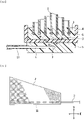
Fig. 2] Fig. 2 is a cross-sectional view of the biological electrode according to the first embodiment of the present invention. - [
Fig. 3] Fig. 3 is a diagram illustrating a conductive fabric and a thin metallic wire according to the first embodiment of the present invention which are unfolded. - [
Fig. 4] Fig. 4 is a diagram illustrating a case where the biological electrode according to the first embodiment of the present invention is installed as a cardiac pacemaker. - [
Fig. 5] Fig. 5 is a cross-sectional view of the biological electrode according to the first embodiment of the present invention which is installed. - [
Fig. 6] Fig. 6 is a perspective view of a biological electrode according to a second embodiment of the present invention. - [
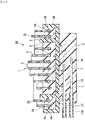
Fig. 7] Fig. 7 is a cross-sectional view of the biological electrode according to the second embodiment of the present invention. - [
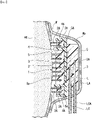
Fig. 8] Fig. 8 is a diagram illustrating a case where the biological electrode according to the second embodiment of the present invention is installed as a cardiac pacemaker. - [
Fig. 9] Fig. 9 is a cross-sectional view of the biological electrode according to the second embodiment of the present invention which is installed. - A first embodiment of the present invention will be described with reference to
Fig. 1 to Fig. 5 . - A
biological electrode 1 according to the present embodiment is an electrode used for sensing and so forth (including sensing, pacing, and transmission and reception of an electric signal) in a cardiac pacemaker, a cochlear implant, a brain-machine interface, or the like, for example. That is, thebiological electrode 1 according to the present embodiment may be used for a cardiac pacemaker, a cochlear implant, a brain-machine interface, or the like. Thebiological electrode 1 according to the present embodiment may be used for a device performing sensing and so forth of a biological organ which expands and contracts such as a heart or a skeletal muscle. - As illustrated in
Fig. 1 andFig. 2 , thebiological electrode 1 includes aconductive fabric 2, a thinmetallic wire 3, apedestal 4, and a fillingmaterial 5. - The
conductive fabric 2 is formed of base fibers which are filled with a conductor containing conductive polymers and/or to which the conductor is adhered. Conductive polymers are used as the conductor, and the rigidity of theconductive fabric 2 can be made lower than a case where a metal material is used as the conductor. Theconductive fabric 2 is supported in a roll shape. - As illustrated in
Fig. 3 , in the present embodiment, the unfoldedconductive fabric 2 has a generally trapezoidal shape but may have a quadrangular shape, another polygonal shape, a circular shape, or the like as long as the shape has a certain surface area. - The
conductive fabric 2 is formed such that the dimension in a length direction E is on the order of 20 mm. Theconductive fabric 2 is formed such that the dimension in a width direction W orthogonal to the length direction E of theconductive fabric 2 is on the order of 3 mm to 4 mm in the largest portion and is on the order of 2 mm to 3.5 mm in the smallest portion. - A formation method of the
conductive fabric 2 may be formation by knitting, formation by weaving, formation as a non-woven fabric, using one kind of those, or using a combination of two or more kinds of those. - As the conductive polymers used for the
conductive fabric 2, a polythiophene-based conductive polymer such as PEDOT-PSS {poly(3,4-ethylenedioxythiophene)-poly(styrene sulfonate)}, polyacetylene-based, polyaniline-based, and polypyrrole-based conductive polymers, and so forth are used. - The conductor used for the
conductive fabric 2 may contain an additive other than the conductive polymers. As additives, for example, glycerol, sorbitol, polyethylene glycol-polypropylene glycol copolymer, ethylene glycol, sphingosine, phosphatidylcholine, and so forth are raised. The additive contained in the conductor may be one kind, or two or more kinds may be used in combination. - The additives of the above examples can be used for the purpose of adjusting wetting characteristics of the
conductive fabric 2 or can be used, by giving flexibility, for the purpose of improving affinity for a biological tissue (skin or tissue) in use as the biological electrode. - Note that as specific examples of adjustment of the wetting characteristics, for example, adjustment of water absorbency, prevention of excessive swelling or shrinkage in moistening or drying, and so forth are raised.
- As the base fibers used for the
conductive fabric 2, animal fibers such as silk and animal hairs, vegetable fibers such as cotton and hemp, synthetic fibers formed of nylon, polyester, acrylic resin, polyvinyl chloride, polyurethane, and so forth, mixed-spun fibers and regenerated fibers of those, and so forth are used. - As a method for filling the base fibers with the conductor or adhering conductor to the base fibers, a method of filling gaps of the base fibers with the conductor, a method of covering the base fibers by the conductor, a method of intertwining the base fibers with the conductor formed into a fiber-like state, or a method of combining those together can be applied.
- Polythiophene-based, polyacetylene-based, polyaniline-based, and polypyrrole-based conductive polymers have excellent conductivity and hydrophilicity. PEDOT-PSS as one kind of polythiophene-based conductive polymer particularly has excellent conductivity, hydrophilicity, and biocompatibility and have excellent adhesiveness to synthetic fibers of silk, polyester, and so forth. Consequently, the
conductive fabric 2 using PEDOT-PSS as the conductive polymers and using synthetic fibers of silk, polyester, and so forth as the base fibers have excellent biocompatibility, conductivity, flexibility, and strength together. - As the thin
metallic wire 3, a material having high biocompatibility is used, and for example, a platinum-iridium alloy, platinum, gold, titanium, silver, a cobalt alloy, a nickel alloy, carbon fiber, stainless steel, or the like is used. - A distal end side of the thin
metallic wire 3 is connected with theconductive fabric 2. A base end side of the thinmetallic wire 3 is formed into a spiral shape and has a spring-shaped structure. A base end of the thinmetallic wire 3 is connected with a lead wire L of a cardiac pacemaker or the like, for example. The thinmetallic wire 3 and the lead wire L are connected together by using a crimping sleeve or the like, for example. - In order to secure durability, reliability, and safety, a similar material to the thin
metallic wire 3 is preferably used for the lead wire L, and the lead wire L is preferably formed into a coil shape or a twisted wire shape. - As illustrated in
Fig. 3 , theconductive fabric 2 has asewn portion 3S which the distal end side of the thinmetallic wire 3 is generally linearly sewn into along the length direction E and the thinmetallic wire 3 is thereby connected with. A distal end of the thinmetallic wire 3 is fixed to theconductive fabric 2 by bending, tying, caulking, or the like. - Note that in the present embodiment, the base fibers are connected with the thin
metallic wire 3, and the base fibers are thereafter filled with the conductor. Thus, the conductor is fused with the thinmetallic wire 3 at the same time as formation of theconductive fabric 2. The thinmetallic wire 3 is fused with the conductor, and the conductivity of thebiological electrode 1 is thereby improved. - The
conductive fabric 2 is wound up along thesewn portion 3S and thereby has a roll shape. Thus, as illustrated inFig. 1 , the thinmetallic wire 3 has a whorled shape in thesewn portion 3S. The thinmetallic wire 3 is sewn into theconductive fabric 2 and is wound up together with theconductive fabric 2, and the thinmetallic wire 3 thereby closely contacts with the conductor with which the base fibers with an increased density are filled and/or which is adhered to the base fibers with an increased density. - In the present embodiment, the width of the
conductive fabric 2 from thesewn portion 3S becomes largest at a distal end of thesewn portion 3S, and the width of theconductive fabric 2 from thesewn portion 3S gradually becomes smaller toward a base end of thesewn portion 3S. Thus, theconductive fabric 2 is wound up around the distal end of the sewnportion 3S as a center along the sewnportion 3S, and a protruding shape is thereby formed in which a central portion of theconductive fabric 2 is elevated. - In the present embodiment, the
conductive fabric 2 is wound up around, as the center, the distal end side of the sewnportion 3S on which the width of theconductive fabric 2 from the sewnportion 3S becomes largest; however, the width of theconductive fabric 2 from the sewnportion 3S may be made largest on the base end side of the sewnportion 3S, and theconductive fabric 2 may be wound up around the base end side of the sewnportion 3S as the center. - The
pedestal 4 has a general saucer shape having a recess on theconductive fabric 2 side. As a material of thepedestal 4, a silicone material such as PDMS (polydimethylsiloxane) is used. - The
pedestal 4 is formed to have a thickness of approximately 1 mm. The recess of thepedestal 4 is formed to have a diameter of approximately 4 mm and a depth of approximately 2 mm. Further, theconductive fabric 2 is arranged to be exposed from the recess of thepedestal 4, and thepedestal 4 is formed such that the height of theconductive fabric 2 exposed from the recess of thepedestal 4 falls in a range of approximately 0.5 mm to 2 mm. - The
pedestal 4 is provided between the distal end and the base end of the thinmetallic wire 3, and the thinmetallic wire 3 passes through thepedestal 4. - Gaps among the
conductive fabric 2, the thinmetallic wire 3, thepedestal 4, and the lead wire L are filled with the fillingmaterial 5, and the fillingmaterial 5 supports theconductive fabric 2, the thinmetallic wire 3, thepedestal 4, and the lead wire L. As the fillingmaterial 5, a silicone material such as PDMS is used. - Next, an action of the
biological electrode 1 will be described. As illustrated inFig. 4 , thebiological electrode 1 is inserted in a pocket Mp formed in a mesh M mounted on an installation target part of thebiological electrode 1 and thereby installed, for example. As a material of the mesh M, polyester, silk, or the like is used. Thebiological electrode 1 used as an anode and thebiological electrode 1 used as a cathode are installed. - As illustrated in
Fig. 5 , thebiological electrode 1 is installed such that theconductive fabric 2 contacts with a sensing-and-so-forth target part Sp. - The
biological electrode 1 is installed such that an axis direction of the thinmetallic wire 3 generally agrees with an expansion-contraction direction of transformation of the sensing-and-so-forth target part Sp by a pulse. - The
biological electrode 1 is installed in such a manner, and the sensing-and-so-forth target part Sp is electrically connected with theconductive fabric 2, the thinmetallic wire 3, and the lead wire L which have conductivity. - The
biological electrode 1 contacts with the sensing-and-so-forth target part Sp via theconductive fabric 2 which has flexibility by using fibers as a base material. The thinmetallic wire 3 formed into a spiral shape and having a spring-shaped structure is arranged between the sensing-and-so-forth target part Sp and the lead wire L and buffers pressures received from the lead wire L due to pulsation of the sensing-and-so-forth target part Sp. - The
biological electrode 1 having the above configuration is installed such that theconductive fabric 2 having flexibility and conductivity contacts with the sensing-and-so-forth target part Sp. Further, in thebiological electrode 1, theconductive fabric 2 portion is connected with the lead wire L via the thinmetallic wire 3 formed into the spiral shape and having the spring-shaped structure. Thus, thebiological electrode 1 contacts with the sensing-and-so-forth target part Sp while having proper buffering characteristics against transformation of the sensing-and-so-forth target part Sp which accompanies a pulse and can reduce a pressure exerted on a biological tissue. - In the
biological electrode 1, the base fibers of theconductive fabric 2 to contact with the sensing-and-so-forth target part Sp are filled with the conductor, and/or the conductor is adhered to the base fibers, the conductor is distributed to the wholeconductive fabric 2, and thebiological electrode 1 can thus maintain a function of an electrode even when being worn. In thebiological electrode 1, theconductive fabric 2 is supported in a roll shape while a portion in which the width of theconductive fabric 2 is largest is set as the center and has a protruding shape in which its central portion is elevated, the protruding shape contacts with the sensing-and-so-forth target part Sp, and a contact state is thus stabilized. - Because the thin
metallic wire 3 of thebiological electrode 1 has the spring-shaped structure which is generally coaxial with the direction of transformation of the sensing-and-so-forth target part Sp which accompanies a pulse, a stress produced by a pulse is not concentrated into a specific portion but is dispersed, and fracture and wire breakage are less likely to occur. - Further, the
biological electrode 1 is integrally formed by filling the gaps among theconductive fabric 2, the thinmetallic wire 3, and the lead wire L with the fillingmaterial 5 using a silicone material. Thus, thebiological electrode 1 has flexibility and can endure a mechanical stress in installation. In addition, theconductive fabric 2 of thebiological electrode 1 draws the fillingmaterial 5 by capillary action in filling with the fillingmaterial 5. A space between theconductive fabric 2 and the thinmetallic wire 3 is filled up with the fillingmaterial 5 drawn toward theconductive fabric 2, and insulation between theconductive fabric 2 and the thinmetallic wire 3 is thereby enhanced. The insulation between theconductive fabric 2 and the thinmetallic wire 3 is enhanced, a spreading amount of a current flowing through theconductive fabric 2 into body fluids is thereby regulated, and loss of current is reduced. - Next, a second embodiment of the present invention will be described with reference to
Fig. 6 to Fig. 9 . - Similarly to the
biological electrode 1, abiological electrode 1A according to the present embodiment is an electrode used for sensing and so forth (including sensing, pacing, and transmission and reception of an electric signal) in a cardiac pacemaker, a cochlear implant, a brain-machine interface, or the like, for example. That is, thebiological electrode 1 according to the present embodiment may be used for a cardiac pacemaker. - As illustrated in
Fig. 6 andFig. 7 , in addition to the configuration of thebiological electrode 1, thebiological electrode 1A includes aconductive fabric 2A, a thinmetallic wire 3A, apedestal 4A, and a fillingmaterial 5A which are arranged to surround thebiological electrode 1. The relationship among theconductive fabric 2A, the thinmetallic wire 3A, thepedestal 4A, and the fillingmaterial 5A is similar to the relationship among theconductive fabric 2, the thinmetallic wire 3, thepedestal 4, and the fillingmaterial 5. - A configuration of the
conductive fabric 2A is similar to theconductive fabric 2. Theconductive fabric 2A is wound to surround an outer periphery of thepedestal 4 of thebiological electrode 1. - A configuration of the thin
metallic wire 3A is similar to the thinmetallic wire 3. A base end of the thinmetallic wire 3A is connected with a lead wire LA of a cardiac pacemaker or the like, for example. The thinmetallic wire 3A and the lead wire LA are connected together by using a crimping sleeve or the like, for example. - In order to secure durability, reliability, and safety, a similar material to the thin
metallic wire 3A is preferably used for the lead wire LA, and the lead wire LA is preferably formed into a coil shape or a twisted wire shape. - A bottom surface of the
pedestal 4A is generally flush with a bottom surface of thepedestal 4. An inner periphery of thepedestal 4A and the outer periphery of thepedestal 4 are formed such that the distance therebetween is approximately 1 mm. A recess of thepedestal 4A is formed to have a depth of approximately 1.35 mm. Further, theconductive fabric 2A is arranged to be exposed from the recess of thepedestal 4A, and thepedestal 4A is formed such that the height of theconductive fabric 2 exposed from the recess of thepedestal 4A falls in a range of approximately 0.5 mm to 2 mm. - As a material of the
pedestal 4A, a silicone material such as PDMS (polydimethylsiloxane) is used. Thepedestal 4A is provided between a distal end and the base end of the thinmetallic wire 3A, and the thinmetallic wire 3A passes through thepedestal 4A. - A configuration of the filling
material 5A is similar to the fillingmaterial 5. Gaps among theconductive fabric 2A, the thinmetallic wire 3A, and thepedestal 4A are filled with the fillingmaterial 5A, and the fillingmaterial 5A supports theconductive fabric 2A, the thinmetallic wire 3A, and thepedestal 4A. - On the base end side of the thin
metallic wire 3A relative to thepedestal 4A, gaps among the thinmetallic wire 3A, thepedestal 4A, and the lead wire LA are filled with the fillingmaterial 5, and the fillingmaterial 5 supports the thinmetallic wire 3A, thepedestal 4A, and the lead wire LA. - Next, an action of the
biological electrode 1A will be described. As illustrated inFig. 8 , similarly to thebiological electrode 1, thebiological electrode 1A is inserted in the pocket Mp formed in the mesh M mounted on an installation target part of thebiological electrode 1A and thereby installed, for example. - The
conductive fabric 2, the thinmetallic wire 3, and the lead wire L serve as one of an anode electrode and a cathode electrode, and theconductive fabric 2A, the thinmetallic wire 3A, and the lead wire LA serve as the other of the cathode electrode and the anode electrode. - As illustrated in
Fig. 9 , thebiological electrode 1A is installed such that theconductive fabric 2 and theconductive fabric 2A contact with the sensing-and-so-forth target part Sp. - The
biological electrode 1A is installed such that axis directions of the thinmetallic wire 3 and the thinmetallic wire 3A generally agree with an expansion-contraction direction of transformation of the sensing-and-so-forth target part Sp by a pulse. - The
biological electrode 1A is installed in such a manner, and the sensing-and-so-forth target part Sp is electrically connected with theconductive fabric 2, the thinmetallic wire 3, and the lead wire L which have conductivity. Further, the sensing-and-so-forth target part Sp is electrically connected with theconductive fabric 2A, the thinmetallic wire 3A, and the lead wire LA which have conductivity. - The
biological electrode 1A contacts with the sensing-and-so-forth target part Sp via theconductive fabric 2 and theconductive fabric 2A which have flexibility by using fibers as a base material. The thinmetallic wire 3 and the thinmetallic wire 3A which are formed into spiral shapes and have spring-shaped structures are arranged between the sensing-and-so-forth target part Sp and the lead wire L and lead wire LA and buffer pressures received from the lead wire L and lead wire LA due to pulsation of the sensing-and-so-forth target part Sp. - The
biological electrode 1A having the above configuration is installed such that theconductive fabric 2 and theconductive fabric 2A which have flexibility and conductivity contact with the sensing-and-so-forth target part Sp. Further, in thebiological electrode 1A, theconductive fabric 2 portion and theconductive fabric 2A portion are connected with the lead wire L and the lead wire LA via the thinmetallic wire 3 and the thinmetallic wire 3A which are formed into the spiral shapes and have the spring-shaped structures. Thus, thebiological electrode 1A contacts with the sensing-and-so-forth target part Sp while having proper buffering characteristics against transformation of the sensing-and-so-forth target part Sp which accompanies a pulse and can reduce a pressure exerted on a biological tissue. - In the
biological electrode 1A, the base fibers of theconductive fabric 2 and theconductive fabric 2A which contact with the sensing-and-so-forth target part Sp are filled with the conductor, and/or the conductor is adhered to the base fibers, and the conductor is distributed to the wholeconductive fabric 2 and the wholeconductive fabric 2A. Thus, thebiological electrode 1A can maintain a function of an electrode even when being worn. In thebiological electrode 1A, theconductive fabric 2 and theconductive fabric 2A are supported in roll shapes while portions in which the widths of theconductive fabric 2 and theconductive fabric 2A are largest are set as the centers and have protruding shapes in which their central portions are elevated, the protruding shapes contact with the sensing-and-so-forth target part Sp, and a contact state is thus stabilized. - Because the thin
metallic wire 3 and the thinmetallic wire 3A of thebiological electrode 1A have the spring-shaped structures which are generally coaxial with the direction of transformation of the sensing-and-so-forth target part Sp which accompanies a pulse, a stress produced by a pulse is not concentrated into a specific portion but is dispersed, and fracture and wire breakage are less likely to occur. - Further, the
biological electrode 1A is integrally formed by filling the gaps among theconductive fabric 2, the thinmetallic wire 3, and the lead wire L and the gaps among theconductive fabric 2A, the thinmetallic wire 3A, and the lead wire LA with the fillingmaterial 5 and the fillingmaterial 5A which use a silicone material. Thus, thebiological electrode 1A has flexibility and can endure a mechanical stress in installation. In addition, theconductive fabric 2 and theconductive fabric 2A of thebiological electrode 1A draw the fillingmaterial 5 and the fillingmaterial 5A by capillary action in filling with the fillingmaterial 5 and the fillingmaterial 5A. The space between theconductive fabric 2 and the thinmetallic wire 3 and a space between theconductive fabric 2A and the thinmetallic wire 3A are filled up with the fillingmaterial 5 and the fillingmaterial 5A which are drawn toward theconductive fabric 2 and theconductive fabric 2A. Thus, the insulation between theconductive fabric 2 and the thinmetallic wire 3 and insulation between theconductive fabric 2A and the thinmetallic wire 3A are enhanced. The insulation between theconductive fabric 2 and the thinmetallic wire 3 and the insulation between theconductive fabric 2A and the thinmetallic wire 3A are enhanced, spreading amounts of currents flowing through theconductive fabric 2 and theconductive fabric 2A into body fluids are thereby regulated, and loss of current is reduced. - In the foregoing, the embodiments of the present invention have been described with reference to the drawings. However, specific configurations are not limited to those embodiments, and the present invention includes design changes and so forth made without departing from the scope of the gist of the present invention. Further, it is possible to make configurations by appropriately combining configuration elements which are described in the above-described embodiments and modification examples described in the following.
- For example, the
conductive fabric 2 or theconductive fabric 2A is formed by filling the base fibers with the conductor or adhering the conductor to the base fibers, connection between theconductive fabric 2 and the thinmetallic wire 3 or connection between theconductive fabric 2A and the thinmetallic wire 3A is thereafter performed, the conductor is fused with the thinmetallic wire 3 or the thinmetallic wire 3A, and thebiological electrode 1 or thebiological electrode 1A may thereby be formed. - In the
biological electrode 1 or thebiological electrode 1A, instead of the thinmetallic wire 3 or the thinmetallic wire 3A, a conductor formed into a string shape may be used. - In the
biological electrode 1 or thebiological electrode 1A, the thinmetallic wire 3 or the thinmetallic wire 3A may be exposed from the fillingmaterial 5. In such a case, a portion of the thinmetallic wire 3 or the thinmetallic wire 3A is covered, the portion being exposed from the fillingmaterial 5. - As long as a shape can be retained only by the filling
material 5 or the fillingmaterial 5A, thebiological electrode 1 or thebiological electrode 1A may not have to include thepedestal 4 or thepedestal 4A. - The
conductive fabric 2 or theconductive fabric 2A of thebiological electrode 1 or thebiological electrode 1A may be wound up around a portion with the smallest width as a center in accordance with the shape of the sensing-and-so-forth target part Sp. - The thin
metallic wire 3 or the thinmetallic wire 3A of thebiological electrode 1 or thebiological electrode 1A may not have to be sewn as long as the thinmetallic wire 3 or the thinmetallic wire 3A is connected with theconductive fabric 2 or theconductive fabric 2A. - In the
biological electrode 1 or thebiological electrode 1A, the conductive polymers may not have to be contained in the conductor. - In the
biological electrode 1 or thebiological electrode 1A, the conductor may not have to be fused with the thinmetallic wire 3 as long as the conductor and the thinmetallic wire 3 are electrically connected together. -
- 1, 1A
- biological electrode
- 2, 2A
- conductive fabric
- 3, 3A
- thin metallic wire
- 3S
- sewn portion
- 4, 4A
- pedestal
- 5, 5A
- filling material
- Ht
- heart
- L, LA
- lead
- LC, LCA
- cover
- M
- mesh
- Mp
- Sp
- sensing-and-so-forth target part
Claims (7)
- A biological electrode comprising:a conductive fabric formed of base fibers which are filled with a conductor and/or to which the conductor is adhered;a thin metallic wire formed into a spiral shape and connected with the conductive fabric at a distal end of the thin metallic wire; anda filling material with which a gap between the conductive fabric and the thin metallic wire is filled and which supports the conductive fabric and the thin metallic wire, whereinthe conductive fabric is supported in a roll shape, andthe conductor is electrically connected with the thin metallic wire.
- The biological electrode according to claim 1, wherein
the conductor contains conductive polymers. - The biological electrode according to claim 1 or 2, whereinthe thin metallic wire has a sewn portion in which a side of the distal end is generally linearly sewn into the conductive fabric,a width of the conductive fabric, the width being orthogonal to the sewn portion, gradually becomes larger from a base end to a distal end of the sewn portion, and the conductive fabric is formed into a roll shape around the distal end of the sewn portion as a center along the sewn portion.
- The biological electrode according to any one of claims 1 to 3, wherein
the conductive polymers contain any of polythiophene-based, polyacetylene-based, polyaniline-based, and polypyrrole-based conductive polymers. - The biological electrode according to any one of claims 1 to 4, further comprising
a pedestal that is formed between the distal end and a base end of the thin metallic wire and supports the conductive fabric and the thin metallic wire. - The biological electrode according to claim 1 or 5, further comprising:the conductive fabric and the thin metallic wire that are used as an anode; andthe conductive fabric and the thin metallic wire that are used as a cathode, whereinthe conductive fabric and the thin metallic wire that are used as the anode are insulated from the conductive fabric and the thin metallic wire that are used as the cathode by the filling material.
- A cardiac pacemaker comprising
the biological electrode according to any one of claims 1 to 6.
Applications Claiming Priority (1)
| Application Number | Priority Date | Filing Date | Title |
|---|---|---|---|
| PCT/JP2019/042387 WO2021084619A1 (en) | 2019-10-29 | 2019-10-29 | Bioelectrode and cardiac pacemaker |
Publications (3)
| Publication Number | Publication Date |
|---|---|
| EP4032582A1 true EP4032582A1 (en) | 2022-07-27 |
| EP4032582A4 EP4032582A4 (en) | 2023-06-07 |
| EP4032582B1 EP4032582B1 (en) | 2024-07-10 |
Family
ID=75714938
Family Applications (1)
| Application Number | Title | Priority Date | Filing Date |
|---|---|---|---|
| EP19950944.9A Active EP4032582B1 (en) | 2019-10-29 | 2019-10-29 | Bioelectrode and cardiac pacemaker |
Country Status (4)
| Country | Link |
|---|---|
| US (1) | US12472359B2 (en) |
| EP (1) | EP4032582B1 (en) |
| JP (1) | JP7343808B2 (en) |
| WO (1) | WO2021084619A1 (en) |
Family Cites Families (16)
| Publication number | Priority date | Publication date | Assignee | Title |
|---|---|---|---|---|
| US4971070A (en) * | 1987-06-18 | 1990-11-20 | Medtronic, Inc. | Epicardial patch electrode |
| JP2815982B2 (en) * | 1990-06-12 | 1998-10-27 | 田中貴金属工業株式会社 | Conductive fabric electrode for implantation in the body |
| DE4322130A1 (en) * | 1993-07-02 | 1995-01-12 | Siemens Ag | Implantable defibrillator |
| US6512940B1 (en) * | 2000-10-31 | 2003-01-28 | Medtronic, Inc. | Subcutaneous spiral electrode for sensing electrical signals of the heart |
| US20060167334A1 (en) * | 2003-06-26 | 2006-07-27 | Anstadt Mark P | Method and apparatus for direct mechanical ventricular actuation with favorable conditioning and minimal heart stress |
| US20050288715A1 (en) * | 2003-11-07 | 2005-12-29 | Lilip Lau | Cardiac harness for treating congestive heart failure and for defibrillating and/or pacing/sensing |
| US7515950B2 (en) * | 2004-08-17 | 2009-04-07 | Healy James W | Biomedical electrodes and biomedical electrodes for electrostimulation |
| US8936794B2 (en) * | 2006-08-25 | 2015-01-20 | The Regents Of The University Of Michigan | Conducting polymer nanotube actuators for precisely controlled release of medicine and bioactive molecules |
| US20080161893A1 (en) * | 2006-12-29 | 2008-07-03 | Saurav Paul | Fabric electrode head |
| JP5734555B2 (en) * | 2009-10-15 | 2015-06-17 | オリンパス株式会社 | Nerve stimulator |
| EP2895236B1 (en) * | 2012-09-11 | 2018-08-15 | Native Cardiocascular LLC | Device for targeted tissue drug delivery |
| EP3052017B1 (en) * | 2013-10-02 | 2019-12-11 | The Board of Trustees of the University of Illionis | Organ mounted electronics |
| KR101741187B1 (en) * | 2014-11-11 | 2017-05-30 | 서울대학교산학협력단 | Mesh Electrode for Global Resynchronization Therapy and Process for Manufacturing the Same |
| EP3206212B1 (en) * | 2016-02-15 | 2022-03-02 | Nokia Technologies Oy | An apparatus and method of forming an apparatus comprising two dimensional material |
| JP6725878B2 (en) * | 2016-07-11 | 2020-07-22 | Smk株式会社 | Biomedical electrode and garment with biomedical electrode |
| JPWO2018155449A1 (en) * | 2017-02-27 | 2019-11-14 | シャープ株式会社 | Electrode apparatus and biological information measuring device |
-
2019
- 2019-10-29 JP JP2021553933A patent/JP7343808B2/en active Active
- 2019-10-29 WO PCT/JP2019/042387 patent/WO2021084619A1/en not_active Ceased
- 2019-10-29 US US17/770,243 patent/US12472359B2/en active Active
- 2019-10-29 EP EP19950944.9A patent/EP4032582B1/en active Active
Also Published As
| Publication number | Publication date |
|---|---|
| US20220379111A1 (en) | 2022-12-01 |
| EP4032582A4 (en) | 2023-06-07 |
| WO2021084619A1 (en) | 2021-05-06 |
| JPWO2021084619A1 (en) | 2021-05-06 |
| US12472359B2 (en) | 2025-11-18 |
| JP7343808B2 (en) | 2023-09-13 |
| EP4032582B1 (en) | 2024-07-10 |
Similar Documents
| Publication | Publication Date | Title |
|---|---|---|
| US4135518A (en) | Body implantable lead and electrode | |
| US5330520A (en) | Implantable electrode and sensor lead apparatus | |
| US5324321A (en) | Medical electrical lead having sigmoidal conductors and non-circular lumens | |
| CN102361665B (en) | Implantable electrode with variable mechanical modulation wiring | |
| CN103093857B (en) | Electrode wires and apply the pacemaker of this electrode wires | |
| EP0293499A1 (en) | Implantable multi-pole coaxial lead | |
| JP5537213B2 (en) | Electrical stimulation electrode assembly | |
| JP2004510508A (en) | Biologically stable guide with small French number | |
| JP2004510564A (en) | Insertion device for cochlear implant electrode train | |
| US20010018607A1 (en) | Co-extruded, multi-lumen medical lead | |
| US4971070A (en) | Epicardial patch electrode | |
| CN105536141B (en) | A kind of embedded nerve stimulator electrode cable contact structure | |
| CN103093865A (en) | Pacemaker electrode line and pacemaker | |
| US20090243953A1 (en) | Enhanced implantable di-pole antenna system and method | |
| US20160339234A1 (en) | Impact Protection for Implantable Electric Lead | |
| EP4032582B1 (en) | Bioelectrode and cardiac pacemaker | |
| EP4032581B1 (en) | Bioelectrode and cardiac pacemaker | |
| US9112325B2 (en) | Contact configuration, contact assembly, implantable apparatus and electrode line | |
| US20100057151A1 (en) | Device for the defibrillation of the heart | |
| CN107335134B (en) | Implantable nerve stimulation electrodes | |
| WO2005072819A1 (en) | Antithrombogenic medical device | |
| JP2010273912A (en) | Medical lead and lead system | |
| KR101933032B1 (en) | Carbon Nanotube-based CI Electrode Array | |
| RU2146155C1 (en) | Endocardial electrode | |
| CN223874254U (en) | Electrode lead and nerve stimulation system |
Legal Events
| Date | Code | Title | Description |
|---|---|---|---|
| STAA | Information on the status of an ep patent application or granted ep patent |
Free format text: STATUS: THE INTERNATIONAL PUBLICATION HAS BEEN MADE |
|
| PUAI | Public reference made under article 153(3) epc to a published international application that has entered the european phase |
Free format text: ORIGINAL CODE: 0009012 |
|
| STAA | Information on the status of an ep patent application or granted ep patent |
Free format text: STATUS: REQUEST FOR EXAMINATION WAS MADE |
|
| 17P | Request for examination filed |
Effective date: 20220420 |
|
| AK | Designated contracting states |
Kind code of ref document: A1 Designated state(s): AL AT BE BG CH CY CZ DE DK EE ES FI FR GB GR HR HU IE IS IT LI LT LU LV MC MK MT NL NO PL PT RO RS SE SI SK SM TR |
|
| DAV | Request for validation of the european patent (deleted) | ||
| DAX | Request for extension of the european patent (deleted) | ||
| A4 | Supplementary search report drawn up and despatched |
Effective date: 20230508 |
|
| RIC1 | Information provided on ipc code assigned before grant |
Ipc: A61B 5/25 20210101ALI20230428BHEP Ipc: A61N 1/362 20060101ALI20230428BHEP Ipc: A61N 1/05 20060101AFI20230428BHEP |
|
| RIC1 | Information provided on ipc code assigned before grant |
Ipc: A61B 5/25 20210101ALI20231113BHEP Ipc: A61N 1/362 20060101ALI20231113BHEP Ipc: A61N 1/05 20060101AFI20231113BHEP |
|
| GRAP | Despatch of communication of intention to grant a patent |
Free format text: ORIGINAL CODE: EPIDOSNIGR1 |
|
| STAA | Information on the status of an ep patent application or granted ep patent |
Free format text: STATUS: GRANT OF PATENT IS INTENDED |
|
| INTG | Intention to grant announced |
Effective date: 20240222 |
|
| GRAS | Grant fee paid |
Free format text: ORIGINAL CODE: EPIDOSNIGR3 |
|
| GRAA | (expected) grant |
Free format text: ORIGINAL CODE: 0009210 |
|
| STAA | Information on the status of an ep patent application or granted ep patent |
Free format text: STATUS: THE PATENT HAS BEEN GRANTED |
|
| AK | Designated contracting states |
Kind code of ref document: B1 Designated state(s): AL AT BE BG CH CY CZ DE DK EE ES FI FR GB GR HR HU IE IS IT LI LT LU LV MC MK MT NL NO PL PT RO RS SE SI SK SM TR |
|
| REG | Reference to a national code |
Ref country code: CH Ref legal event code: EP |
|
| REG | Reference to a national code |
Ref country code: DE Ref legal event code: R096 Ref document number: 602019055216 Country of ref document: DE |
|
| REG | Reference to a national code |
Ref country code: LT Ref legal event code: MG9D |
|
| REG | Reference to a national code |
Ref country code: NL Ref legal event code: MP Effective date: 20240710 |
|
| PG25 | Lapsed in a contracting state [announced via postgrant information from national office to epo] |
Ref country code: PT Free format text: LAPSE BECAUSE OF FAILURE TO SUBMIT A TRANSLATION OF THE DESCRIPTION OR TO PAY THE FEE WITHIN THE PRESCRIBED TIME-LIMIT Effective date: 20241111 |
|
| REG | Reference to a national code |
Ref country code: AT Ref legal event code: MK05 Ref document number: 1701523 Country of ref document: AT Kind code of ref document: T Effective date: 20240710 |
|
| PG25 | Lapsed in a contracting state [announced via postgrant information from national office to epo] |
Ref country code: NL Free format text: LAPSE BECAUSE OF FAILURE TO SUBMIT A TRANSLATION OF THE DESCRIPTION OR TO PAY THE FEE WITHIN THE PRESCRIBED TIME-LIMIT Effective date: 20240710 |
|
| PG25 | Lapsed in a contracting state [announced via postgrant information from national office to epo] |
Ref country code: PT Free format text: LAPSE BECAUSE OF FAILURE TO SUBMIT A TRANSLATION OF THE DESCRIPTION OR TO PAY THE FEE WITHIN THE PRESCRIBED TIME-LIMIT Effective date: 20241111 Ref country code: NL Free format text: LAPSE BECAUSE OF FAILURE TO SUBMIT A TRANSLATION OF THE DESCRIPTION OR TO PAY THE FEE WITHIN THE PRESCRIBED TIME-LIMIT Effective date: 20240710 |
|
| PG25 | Lapsed in a contracting state [announced via postgrant information from national office to epo] |
Ref country code: NO Free format text: LAPSE BECAUSE OF FAILURE TO SUBMIT A TRANSLATION OF THE DESCRIPTION OR TO PAY THE FEE WITHIN THE PRESCRIBED TIME-LIMIT Effective date: 20241010 |
|
| PG25 | Lapsed in a contracting state [announced via postgrant information from national office to epo] |
Ref country code: GR Free format text: LAPSE BECAUSE OF FAILURE TO SUBMIT A TRANSLATION OF THE DESCRIPTION OR TO PAY THE FEE WITHIN THE PRESCRIBED TIME-LIMIT Effective date: 20241011 Ref country code: PL Free format text: LAPSE BECAUSE OF FAILURE TO SUBMIT A TRANSLATION OF THE DESCRIPTION OR TO PAY THE FEE WITHIN THE PRESCRIBED TIME-LIMIT Effective date: 20240710 Ref country code: FI Free format text: LAPSE BECAUSE OF FAILURE TO SUBMIT A TRANSLATION OF THE DESCRIPTION OR TO PAY THE FEE WITHIN THE PRESCRIBED TIME-LIMIT Effective date: 20240710 |
|
| PG25 | Lapsed in a contracting state [announced via postgrant information from national office to epo] |
Ref country code: BG Free format text: LAPSE BECAUSE OF FAILURE TO SUBMIT A TRANSLATION OF THE DESCRIPTION OR TO PAY THE FEE WITHIN THE PRESCRIBED TIME-LIMIT Effective date: 20240710 |
|
| PG25 | Lapsed in a contracting state [announced via postgrant information from national office to epo] |
Ref country code: LV Free format text: LAPSE BECAUSE OF FAILURE TO SUBMIT A TRANSLATION OF THE DESCRIPTION OR TO PAY THE FEE WITHIN THE PRESCRIBED TIME-LIMIT Effective date: 20240710 |
|
| PG25 | Lapsed in a contracting state [announced via postgrant information from national office to epo] |
Ref country code: AT Free format text: LAPSE BECAUSE OF FAILURE TO SUBMIT A TRANSLATION OF THE DESCRIPTION OR TO PAY THE FEE WITHIN THE PRESCRIBED TIME-LIMIT Effective date: 20240710 Ref country code: IS Free format text: LAPSE BECAUSE OF FAILURE TO SUBMIT A TRANSLATION OF THE DESCRIPTION OR TO PAY THE FEE WITHIN THE PRESCRIBED TIME-LIMIT Effective date: 20241110 |
|
| PG25 | Lapsed in a contracting state [announced via postgrant information from national office to epo] |
Ref country code: HR Free format text: LAPSE BECAUSE OF FAILURE TO SUBMIT A TRANSLATION OF THE DESCRIPTION OR TO PAY THE FEE WITHIN THE PRESCRIBED TIME-LIMIT Effective date: 20240710 |
|
| PG25 | Lapsed in a contracting state [announced via postgrant information from national office to epo] |
Ref country code: RS Free format text: LAPSE BECAUSE OF FAILURE TO SUBMIT A TRANSLATION OF THE DESCRIPTION OR TO PAY THE FEE WITHIN THE PRESCRIBED TIME-LIMIT Effective date: 20241010 Ref country code: ES Free format text: LAPSE BECAUSE OF FAILURE TO SUBMIT A TRANSLATION OF THE DESCRIPTION OR TO PAY THE FEE WITHIN THE PRESCRIBED TIME-LIMIT Effective date: 20240710 |
|
| PG25 | Lapsed in a contracting state [announced via postgrant information from national office to epo] |
Ref country code: RS Free format text: LAPSE BECAUSE OF FAILURE TO SUBMIT A TRANSLATION OF THE DESCRIPTION OR TO PAY THE FEE WITHIN THE PRESCRIBED TIME-LIMIT Effective date: 20241010 Ref country code: PL Free format text: LAPSE BECAUSE OF FAILURE TO SUBMIT A TRANSLATION OF THE DESCRIPTION OR TO PAY THE FEE WITHIN THE PRESCRIBED TIME-LIMIT Effective date: 20240710 Ref country code: NO Free format text: LAPSE BECAUSE OF FAILURE TO SUBMIT A TRANSLATION OF THE DESCRIPTION OR TO PAY THE FEE WITHIN THE PRESCRIBED TIME-LIMIT Effective date: 20241010 Ref country code: LV Free format text: LAPSE BECAUSE OF FAILURE TO SUBMIT A TRANSLATION OF THE DESCRIPTION OR TO PAY THE FEE WITHIN THE PRESCRIBED TIME-LIMIT Effective date: 20240710 Ref country code: IS Free format text: LAPSE BECAUSE OF FAILURE TO SUBMIT A TRANSLATION OF THE DESCRIPTION OR TO PAY THE FEE WITHIN THE PRESCRIBED TIME-LIMIT Effective date: 20241110 Ref country code: HR Free format text: LAPSE BECAUSE OF FAILURE TO SUBMIT A TRANSLATION OF THE DESCRIPTION OR TO PAY THE FEE WITHIN THE PRESCRIBED TIME-LIMIT Effective date: 20240710 Ref country code: GR Free format text: LAPSE BECAUSE OF FAILURE TO SUBMIT A TRANSLATION OF THE DESCRIPTION OR TO PAY THE FEE WITHIN THE PRESCRIBED TIME-LIMIT Effective date: 20241011 Ref country code: FI Free format text: LAPSE BECAUSE OF FAILURE TO SUBMIT A TRANSLATION OF THE DESCRIPTION OR TO PAY THE FEE WITHIN THE PRESCRIBED TIME-LIMIT Effective date: 20240710 Ref country code: ES Free format text: LAPSE BECAUSE OF FAILURE TO SUBMIT A TRANSLATION OF THE DESCRIPTION OR TO PAY THE FEE WITHIN THE PRESCRIBED TIME-LIMIT Effective date: 20240710 Ref country code: BG Free format text: LAPSE BECAUSE OF FAILURE TO SUBMIT A TRANSLATION OF THE DESCRIPTION OR TO PAY THE FEE WITHIN THE PRESCRIBED TIME-LIMIT Effective date: 20240710 Ref country code: AT Free format text: LAPSE BECAUSE OF FAILURE TO SUBMIT A TRANSLATION OF THE DESCRIPTION OR TO PAY THE FEE WITHIN THE PRESCRIBED TIME-LIMIT Effective date: 20240710 |
|
| REG | Reference to a national code |
Ref country code: DE Ref legal event code: R097 Ref document number: 602019055216 Country of ref document: DE |
|
| PG25 | Lapsed in a contracting state [announced via postgrant information from national office to epo] |
Ref country code: DK Free format text: LAPSE BECAUSE OF FAILURE TO SUBMIT A TRANSLATION OF THE DESCRIPTION OR TO PAY THE FEE WITHIN THE PRESCRIBED TIME-LIMIT Effective date: 20240710 Ref country code: RO Free format text: LAPSE BECAUSE OF FAILURE TO SUBMIT A TRANSLATION OF THE DESCRIPTION OR TO PAY THE FEE WITHIN THE PRESCRIBED TIME-LIMIT Effective date: 20240710 Ref country code: SM Free format text: LAPSE BECAUSE OF FAILURE TO SUBMIT A TRANSLATION OF THE DESCRIPTION OR TO PAY THE FEE WITHIN THE PRESCRIBED TIME-LIMIT Effective date: 20240710 |
|
| PG25 | Lapsed in a contracting state [announced via postgrant information from national office to epo] |
Ref country code: EE Free format text: LAPSE BECAUSE OF FAILURE TO SUBMIT A TRANSLATION OF THE DESCRIPTION OR TO PAY THE FEE WITHIN THE PRESCRIBED TIME-LIMIT Effective date: 20240710 |
|
| PG25 | Lapsed in a contracting state [announced via postgrant information from national office to epo] |
Ref country code: CZ Free format text: LAPSE BECAUSE OF FAILURE TO SUBMIT A TRANSLATION OF THE DESCRIPTION OR TO PAY THE FEE WITHIN THE PRESCRIBED TIME-LIMIT Effective date: 20240710 |
|
| PG25 | Lapsed in a contracting state [announced via postgrant information from national office to epo] |
Ref country code: SK Free format text: LAPSE BECAUSE OF FAILURE TO SUBMIT A TRANSLATION OF THE DESCRIPTION OR TO PAY THE FEE WITHIN THE PRESCRIBED TIME-LIMIT Effective date: 20240710 Ref country code: IT Free format text: LAPSE BECAUSE OF FAILURE TO SUBMIT A TRANSLATION OF THE DESCRIPTION OR TO PAY THE FEE WITHIN THE PRESCRIBED TIME-LIMIT Effective date: 20240710 |
|
| PLBE | No opposition filed within time limit |
Free format text: ORIGINAL CODE: 0009261 |
|
| STAA | Information on the status of an ep patent application or granted ep patent |
Free format text: STATUS: NO OPPOSITION FILED WITHIN TIME LIMIT |
|
| REG | Reference to a national code |
Ref country code: CH Ref legal event code: PL |
|
| 26N | No opposition filed |
Effective date: 20250411 |
|
| GBPC | Gb: european patent ceased through non-payment of renewal fee |
Effective date: 20241029 |
|
| PG25 | Lapsed in a contracting state [announced via postgrant information from national office to epo] |
Ref country code: MC Free format text: LAPSE BECAUSE OF FAILURE TO SUBMIT A TRANSLATION OF THE DESCRIPTION OR TO PAY THE FEE WITHIN THE PRESCRIBED TIME-LIMIT Effective date: 20240710 |
|
| PG25 | Lapsed in a contracting state [announced via postgrant information from national office to epo] |
Ref country code: GB Free format text: LAPSE BECAUSE OF NON-PAYMENT OF DUE FEES Effective date: 20241029 |
|
| PG25 | Lapsed in a contracting state [announced via postgrant information from national office to epo] |
Ref country code: BE Free format text: LAPSE BECAUSE OF NON-PAYMENT OF DUE FEES Effective date: 20241031 Ref country code: LU Free format text: LAPSE BECAUSE OF NON-PAYMENT OF DUE FEES Effective date: 20241029 |
|
| PG25 | Lapsed in a contracting state [announced via postgrant information from national office to epo] |
Ref country code: FR Free format text: LAPSE BECAUSE OF NON-PAYMENT OF DUE FEES Effective date: 20241031 |
|
| PG25 | Lapsed in a contracting state [announced via postgrant information from national office to epo] |
Ref country code: CH Free format text: LAPSE BECAUSE OF NON-PAYMENT OF DUE FEES Effective date: 20241031 |
|
| REG | Reference to a national code |
Ref country code: BE Ref legal event code: MM Effective date: 20241031 |
|
| PG25 | Lapsed in a contracting state [announced via postgrant information from national office to epo] |
Ref country code: SE Free format text: LAPSE BECAUSE OF FAILURE TO SUBMIT A TRANSLATION OF THE DESCRIPTION OR TO PAY THE FEE WITHIN THE PRESCRIBED TIME-LIMIT Effective date: 20240710 |
|
| PG25 | Lapsed in a contracting state [announced via postgrant information from national office to epo] |
Ref country code: IE Free format text: LAPSE BECAUSE OF NON-PAYMENT OF DUE FEES Effective date: 20241029 |
|
| PGFP | Annual fee paid to national office [announced via postgrant information from national office to epo] |
Ref country code: DE Payment date: 20251021 Year of fee payment: 7 |
|
| PG25 | Lapsed in a contracting state [announced via postgrant information from national office to epo] |
Ref country code: HU Free format text: LAPSE BECAUSE OF FAILURE TO SUBMIT A TRANSLATION OF THE DESCRIPTION OR TO PAY THE FEE WITHIN THE PRESCRIBED TIME-LIMIT; INVALID AB INITIO Effective date: 20191029 |
|
| REG | Reference to a national code |
Ref country code: DE Ref legal event code: R081 Ref document number: 602019055216 Country of ref document: DE Owner name: NTT, INC., JP Free format text: FORMER OWNER: NIPPON TELEGRAPH AND TELEPHONE CORPORATION, TOKYO, JP |
|
| PG25 | Lapsed in a contracting state [announced via postgrant information from national office to epo] |
Ref country code: CY Free format text: LAPSE BECAUSE OF FAILURE TO SUBMIT A TRANSLATION OF THE DESCRIPTION OR TO PAY THE FEE WITHIN THE PRESCRIBED TIME-LIMIT; INVALID AB INITIO Effective date: 20191029 |