EP4032568B1 - Closed stopcock - Google Patents
Closed stopcock Download PDFInfo
- Publication number
- EP4032568B1 EP4032568B1 EP22158169.7A EP22158169A EP4032568B1 EP 4032568 B1 EP4032568 B1 EP 4032568B1 EP 22158169 A EP22158169 A EP 22158169A EP 4032568 B1 EP4032568 B1 EP 4032568B1
- Authority
- EP
- European Patent Office
- Prior art keywords
- fluid flow
- port
- stopcock
- bore
- fluid
- Prior art date
- Legal status (The legal status is an assumption and is not a legal conclusion. Google has not performed a legal analysis and makes no representation as to the accuracy of the status listed.)
- Active
Links
Images










Classifications
-
- A—HUMAN NECESSITIES
- A61—MEDICAL OR VETERINARY SCIENCE; HYGIENE
- A61B—DIAGNOSIS; SURGERY; IDENTIFICATION
- A61B5/00—Measuring for diagnostic purposes; Identification of persons
- A61B5/15—Devices for taking samples of blood
- A61B5/150992—Blood sampling from a fluid line external to a patient, such as a catheter line, combined with an infusion line; Blood sampling from indwelling needle sets, e.g. sealable ports, luer couplings or valves
-
- A—HUMAN NECESSITIES
- A61—MEDICAL OR VETERINARY SCIENCE; HYGIENE
- A61M—DEVICES FOR INTRODUCING MEDIA INTO, OR ONTO, THE BODY; DEVICES FOR TRANSDUCING BODY MEDIA OR FOR TAKING MEDIA FROM THE BODY; DEVICES FOR PRODUCING OR ENDING SLEEP OR STUPOR
- A61M1/00—Suction or pumping devices for medical purposes; Devices for carrying-off, for treatment of, or for carrying-over, body-liquids; Drainage systems
- A61M1/36—Other treatment of blood in a by-pass of the natural circulatory system, e.g. temperature adaptation, irradiation ; Extra-corporeal blood circuits
- A61M1/3621—Extra-corporeal blood circuits
- A61M1/3639—Blood pressure control, pressure transducers specially adapted therefor
-
- A—HUMAN NECESSITIES
- A61—MEDICAL OR VETERINARY SCIENCE; HYGIENE
- A61M—DEVICES FOR INTRODUCING MEDIA INTO, OR ONTO, THE BODY; DEVICES FOR TRANSDUCING BODY MEDIA OR FOR TAKING MEDIA FROM THE BODY; DEVICES FOR PRODUCING OR ENDING SLEEP OR STUPOR
- A61M39/00—Tubes, tube connectors, tube couplings, valves, access sites or the like, specially adapted for medical use
- A61M39/22—Valves or arrangement of valves
- A61M39/223—Multiway valves
-
- A—HUMAN NECESSITIES
- A61—MEDICAL OR VETERINARY SCIENCE; HYGIENE
- A61M—DEVICES FOR INTRODUCING MEDIA INTO, OR ONTO, THE BODY; DEVICES FOR TRANSDUCING BODY MEDIA OR FOR TAKING MEDIA FROM THE BODY; DEVICES FOR PRODUCING OR ENDING SLEEP OR STUPOR
- A61M5/00—Devices for bringing media into the body in a subcutaneous, intra-vascular or intramuscular way; Accessories therefor, e.g. filling or cleaning devices, arm-rests
- A61M5/14—Infusion devices, e.g. infusing by gravity; Blood infusion; Accessories therefor
- A61M5/168—Means for controlling media flow to the body or for metering media to the body, e.g. drip meters, counters ; Monitoring media flow to the body
- A61M5/16877—Adjusting flow; Devices for setting a flow rate
-
- A—HUMAN NECESSITIES
- A61—MEDICAL OR VETERINARY SCIENCE; HYGIENE
- A61M—DEVICES FOR INTRODUCING MEDIA INTO, OR ONTO, THE BODY; DEVICES FOR TRANSDUCING BODY MEDIA OR FOR TAKING MEDIA FROM THE BODY; DEVICES FOR PRODUCING OR ENDING SLEEP OR STUPOR
- A61M5/00—Devices for bringing media into the body in a subcutaneous, intra-vascular or intramuscular way; Accessories therefor, e.g. filling or cleaning devices, arm-rests
- A61M5/14—Infusion devices, e.g. infusing by gravity; Blood infusion; Accessories therefor
- A61M5/168—Means for controlling media flow to the body or for metering media to the body, e.g. drip meters, counters ; Monitoring media flow to the body
- A61M5/16877—Adjusting flow; Devices for setting a flow rate
- A61M5/16881—Regulating valves
-
- F—MECHANICAL ENGINEERING; LIGHTING; HEATING; WEAPONS; BLASTING
- F16—ENGINEERING ELEMENTS AND UNITS; GENERAL MEASURES FOR PRODUCING AND MAINTAINING EFFECTIVE FUNCTIONING OF MACHINES OR INSTALLATIONS; THERMAL INSULATION IN GENERAL
- F16K—VALVES; TAPS; COCKS; ACTUATING-FLOATS; DEVICES FOR VENTING OR AERATING
- F16K11/00—Multiple-way valves, e.g. mixing valves; Pipe fittings incorporating such valves
- F16K11/02—Multiple-way valves, e.g. mixing valves; Pipe fittings incorporating such valves with all movable sealing faces moving as one unit
- F16K11/08—Multiple-way valves, e.g. mixing valves; Pipe fittings incorporating such valves with all movable sealing faces moving as one unit comprising only taps or cocks
- F16K11/083—Multiple-way valves, e.g. mixing valves; Pipe fittings incorporating such valves with all movable sealing faces moving as one unit comprising only taps or cocks with tapered plug
- F16K11/0833—Multiple-way valves, e.g. mixing valves; Pipe fittings incorporating such valves with all movable sealing faces moving as one unit comprising only taps or cocks with tapered plug having all the connecting conduits situated in a single plane perpendicular to the axis of the plug
-
- F—MECHANICAL ENGINEERING; LIGHTING; HEATING; WEAPONS; BLASTING
- F16—ENGINEERING ELEMENTS AND UNITS; GENERAL MEASURES FOR PRODUCING AND MAINTAINING EFFECTIVE FUNCTIONING OF MACHINES OR INSTALLATIONS; THERMAL INSULATION IN GENERAL
- F16K—VALVES; TAPS; COCKS; ACTUATING-FLOATS; DEVICES FOR VENTING OR AERATING
- F16K11/00—Multiple-way valves, e.g. mixing valves; Pipe fittings incorporating such valves
- F16K11/02—Multiple-way valves, e.g. mixing valves; Pipe fittings incorporating such valves with all movable sealing faces moving as one unit
- F16K11/08—Multiple-way valves, e.g. mixing valves; Pipe fittings incorporating such valves with all movable sealing faces moving as one unit comprising only taps or cocks
- F16K11/085—Multiple-way valves, e.g. mixing valves; Pipe fittings incorporating such valves with all movable sealing faces moving as one unit comprising only taps or cocks with cylindrical plug
- F16K11/0853—Multiple-way valves, e.g. mixing valves; Pipe fittings incorporating such valves with all movable sealing faces moving as one unit comprising only taps or cocks with cylindrical plug having all the connecting conduits situated in a single plane perpendicular to the axis of the plug
-
- F—MECHANICAL ENGINEERING; LIGHTING; HEATING; WEAPONS; BLASTING
- F16—ENGINEERING ELEMENTS AND UNITS; GENERAL MEASURES FOR PRODUCING AND MAINTAINING EFFECTIVE FUNCTIONING OF MACHINES OR INSTALLATIONS; THERMAL INSULATION IN GENERAL
- F16K—VALVES; TAPS; COCKS; ACTUATING-FLOATS; DEVICES FOR VENTING OR AERATING
- F16K31/00—Actuating devices; Operating means; Releasing devices
- F16K31/44—Mechanical actuating means
- F16K31/60—Handles
- F16K31/602—Pivoting levers, e.g. single-sided
-
- A—HUMAN NECESSITIES
- A61—MEDICAL OR VETERINARY SCIENCE; HYGIENE
- A61M—DEVICES FOR INTRODUCING MEDIA INTO, OR ONTO, THE BODY; DEVICES FOR TRANSDUCING BODY MEDIA OR FOR TAKING MEDIA FROM THE BODY; DEVICES FOR PRODUCING OR ENDING SLEEP OR STUPOR
- A61M39/00—Tubes, tube connectors, tube couplings, valves, access sites or the like, specially adapted for medical use
- A61M39/22—Valves or arrangement of valves
- A61M2039/229—Stopcocks
-
- A—HUMAN NECESSITIES
- A61—MEDICAL OR VETERINARY SCIENCE; HYGIENE
- A61M—DEVICES FOR INTRODUCING MEDIA INTO, OR ONTO, THE BODY; DEVICES FOR TRANSDUCING BODY MEDIA OR FOR TAKING MEDIA FROM THE BODY; DEVICES FOR PRODUCING OR ENDING SLEEP OR STUPOR
- A61M39/00—Tubes, tube connectors, tube couplings, valves, access sites or the like, specially adapted for medical use
- A61M39/22—Valves or arrangement of valves
- A61M39/24—Check- or non-return valves
- A61M2039/2426—Slit valve
-
- A—HUMAN NECESSITIES
- A61—MEDICAL OR VETERINARY SCIENCE; HYGIENE
- A61M—DEVICES FOR INTRODUCING MEDIA INTO, OR ONTO, THE BODY; DEVICES FOR TRANSDUCING BODY MEDIA OR FOR TAKING MEDIA FROM THE BODY; DEVICES FOR PRODUCING OR ENDING SLEEP OR STUPOR
- A61M39/00—Tubes, tube connectors, tube couplings, valves, access sites or the like, specially adapted for medical use
- A61M39/02—Access sites
- A61M39/04—Access sites having pierceable self-sealing members
- A61M39/045—Access sites having pierceable self-sealing members pre-slit to be pierced by blunt instrument
Definitions
- the present invention relates to stopcocks generally, and more specifically to swabbable stopcocks.
- Closed stopcocks typically have a luer activated valve incorporated within one of the stopcock ports for convenient engagement of a medical instrument with the stopcock.
- DE 10 2015 205517 relates to a medical fluid control device for a medical fluid line system, and discloses a stopcock according to the pre-characterizing portion of appended independent claim 1.
- US9016316B2 discloses another example of stopcock.
- the present invention seeks to provide an improved closed stopcock.
- a stopcock comprising a housing element defining a central bore and at least first, second and third ports, and a handle element, which is selectably positionable relative to the housing element, the housing element and the handle element being arrangeable in multiple mutual positions, at least one of the housing element and the handle element defining a first fluid flow passageway communicating between two of said at least first, second and third ports, and a second fluid flow passageway communicating between at least two of the at least first, second and third ports, selection of the ports being in accordance with a relative position of the handle element relative to the housing element; the first fluid flow passageway including a side-to-side extending bore extending through the handle, and the second fluid flow passageway including a fluid flow guide, and a second fluid flow guide extending radially and partially bifurcating one of the at least one of the first, second and third ports, the second fluid flow guide being associated with at least one of the first fluid flow passageway and the second fluid flow passageway, characterized in that said first fluid flow
- the fluid flow guide extends radially towards an inner facing wall of the central bore and partially bifurcates the second fluid flow passageway. Further preferably, the first fluid flow passageway and the second fluid flow passageway are operative simultaneously in at least one of the multiple mutual positions.
- the second fluid flow passageway being configured for enabling flushing an internal volume of at least one of the first, second and third ports by a fluid flow which does not flow entirely through the port whose internal volume is being flushed, and the first fluid flow passageway being configured for increasing a fluid flow rate between two of the at least first, second and third ports.
- the fluid flow guide comprising an outward facing edge which sealingly engages an inner facing wall of the central bore, and when the outward facing edge of the fluid flow guide is not located opposite any of the first, second and third ports, flow of liquid through the second fluid flow passageway is prevented and flow of liquid through the first fluid flow passageway is allowed.
- the stopcock also comprising at least one valve, which is associated with at least one of the first, second and third ports.
- the valve includes an elastomeric element, and wherein at least one of the first fluid flow passageway and the second fluid flow passageway is configured for providing a fluid flow which is sealed from the elastomeric element when the housing element and the handle element are in another one of the mutual positions.
- both the first fluid flow passageway and the second fluid flow passageway are defined by a shaft portion of the handle element.
- the at least one side-to-side extending bore has a semi-circular cross-section.
- the handle element has a partially peripherally-extending recess, selectably defining the second fluid flow passageway, the fluid flow guide extending radially and partially bifurcating the recess.
- the at least one side-to-side extending bore is spaced from the recess.
- the fluid flow rate is increased by at least 25%.
- the first fluid flow passageway is fluidly connected with the second fluid flow passageway in other of said at least one of the mutual positions.
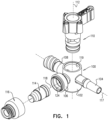
- Fig. 1 is a simplified exploded view illustration of a stopcock constructed and operative in accordance with an embodiment not forming part of the present invention:
- Fig. 1 is a simplified exploded view illustration of a stopcock constructed and operative in accordance with an embodiment not forming part of the present invention
- the stopcock comprises a housing element 100 including a main tubular portion 102 and three side ports, designated by reference numerals 104, 106 and 108 respectively.
- a handle element 110 is arranged to be seated within main tubular portion 102 of housing element 100.
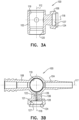
- FIGS. 2A & 2B are simplified pictorial illustrations of the housing element 100 and to Figs. 3A & 3B , which are sectional illustrations thereof.
- tubular portion 102 of housing element 100 is generally cylindrical, arranged about an axis 112, and has side ports 104, 106 and 108 extending in different directions therefrom, typically separated by 90 degrees about axis 112.
- First port 104 is preferably a male port which preferably meets luer standard ISO 594-1
- second port 106 is configured for incorporating a normally closed swabbable valve which is configured to receive a male luer
- third port 108 is preferably a female port, which preferably meets luer standard ISO 594-1.
- Conventional plugs, nuts and covers may be used in association with ports 104 and 108.
- Port 106 of housing element 100 preferably includes a valve employing an elastomeric element 114, held in place by a cap 116, which is welded or otherwise fixed to housing element 100.
- Elastomeric element 114 and cap 116 are commercially available from Halkey-Roberts Corporation of St. Orlando, Fla., USA and described in one or more of U.S. Pat. Nos. 6,651,956 ; 6,089,541 and 6,036,171 .
- valves and valve elements commercially available from other sources such as Becton-Dickinson, Cardinal, Medegen and Filtertek may be employed.
- Ports 104 and 108 are preferably arranged along a mutual longitudinal axis 117 and port 106 is preferably arranged along axis 118, which extends generally perpendicularly to axis 117.
- Tubular portion 102 includes a central bore 119 having a slightly conical configuration, which is formed with a circumferential undercut 120.
- Port 106 defines an interior volume 121, which includes a generally cylindrical bore 122 of a first diameter, adjacent to and extending from central bore 119 and a valve accommodating bore 124 of a second diameter, which is preferably greater than the first diameter, extending generally outwardly of cylindrical bore 122.
- Cylindrical bore 122 defines a first volume 126 and valve accommodating bore 124 defines a second volume 127.
- elastomeric element 114 is adapted to be fixedly seated between cap 116 and port 106, a portion of the elastomeric element 114 is adapted to be seated within second volume 127 of port 106.
- a fluid flow guide 128 preferably bifurcates cylindrical bore 122 of port 106, and extends between the central bore 119 and the elastomeric element 114.
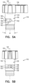
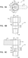
- FIGS. 4A - 5B are simplified pictorial illustrations of the handle element 110 forming part of the stopcock of Fig. 1 , and to Figs. 6A - 6C , which are sectional illustrations thereof.
- the handle element 110 includes a shaft portion 130, which is integrally formed with a top portion 132 from which extends a finger-engageable protrusion 134. It is appreciated that any other suitable general configuration of the top portion of the handle element may alternatively be employed.
- Shaft portion 130 is generally symmetrical about a shaft axis 142 and has a slightly conical outer surface 144, typically having an angle ⁇ (as seen particularly in Fig. 5A ) of 3-4 degrees, which corresponds to the slightly conical configuration of central bore 119 for rotatable sealing engagement therewith.
- shaft portion 130 is typically formed with mutually sealed top and bottom cylindrical recesses 146 and 148, which are sealingly separated by a divider 150.
- At least one fluid flow passage is provided through handle element 110.
- the fluid flow rate is increased by at least 25%.
- the fluid flow rate is increased by at least 50%.
- the fluid flow rate is increased from 300ml/min to 600ml/min.
- the two fluid flow passages are interconnected in some of the mutual relative positions of the handle element 110 and the housing element 100 and that the two fluid flow passages are isolated in other of the mutual relative positions of the handle element 110 and the housing element 100 as described in detail hereinbelow.
- a side-to-side extending bore 152 Disposed generally between recesses 146 and 148 and sealed therefrom is a side-to-side extending bore 152, selectably defining a first fluid flow passageway between two of the selectable ones of side ports 104, 106 and 108 depending on the rotational orientation of the handle element 110 relative to the housing element 100.
- the side-to-side extending bore 152 has a semi-circular cross-section, however it is appreciated that bore 152 can alternatively have any other shape, such as circular, rectangular or other which provides the desired fluid flow rate.
- a partially peripherally-extending recess 153 selectably defining a second fluid flow passageway between selectable ones of side ports 104, 106 and 108 depending on the rotational orientation of the handle element 110 relative to the housing element 100.
- a fluid flow guide 154 Preferably extending radially and partially bifurcating the recess 153 is a fluid flow guide 154, which is configured for directing the flow of liquid between any of ports 104 and 108 through the second fluid flow passageway defined by recess 153 into the internal volume 121 of port 106 for flushing thereof, when the handle element 110 is suitably positioned.
- the radially outward facing edge 156 of fluid flow guide 154 is formed with a suitably tapered configuration in order to prevent liquid flow there past when fluid flow guide 154 is not located opposite a port as described in detail hereinbelow. It is noted that, in other arrangements not forming part of the present invention, the fluid flow guide 154 may alternatively have any other suitable shape, such that the radially outward facing edge 156 thereof can extend towards the inner surface of central bore 119 but slightly spaced therefrom in order to provide minimal fluid flow passage there past when fluid flow guide 154 is not located opposite any of ports 104, 106 and 108.
- fluid communication between opposite ends of bore 152 occurs in parallel to fluid communication along recess 153 at least in some of the mutual relative positions of the handle element 110 and the housing element 100.
- Fluid flow guide 154 directs the flow of liquid between ports 104 and 108 through recess 153 and into the internal volume 121 of port 106 for flushing thereof, when the handle element 110 is suitably positioned. Simultaneously, fluid flow is directed between ports 104 and 108 through bore 152, thereby increasing the fluid flow rate through the stopcock of Fig. 1 .
- the fluid flow guide 154 is formed as a generally flat wall 160, which is adapted to extend up to the inner surface of the inner bore 119 of housing element 100 and a generally wider arcuate concave portion 162 formed on each side of the flat wall 160 and extending slightly outwardly therefrom.
- the concave portion 162 of fluid flow guide 154 is located adjacent bore 152 and typically extends along a relatively minor longitudinal extent of bore 152.
- Fig. 7 is a simplified exploded view illustration of a stopcock constructed and operative in accordance with another embodiment not forming part of the present invention.
- the stopcock comprises a housing element 100, which is preferably identical in all respects to housing element 100 which is illustrated and described with respect to Figs. 2A - 3B .
- the housing element 100 includes a main tubular portion 102 and three side ports, designated by reference numerals 104, 106 and 108 respectively.
- a handle element 210 in accordance with another embodiment is arranged to be seated within main tubular portion 102 of housing element 100.
- a similar elastomeric element 114 and cap 116 are adapted to be seated within port 106 of the housing element 100, in a similar manner as described with respect to Figs. 1 - 3B .
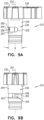
- FIGS. 8A - 9B are simplified pictorial illustrations of the handle element 210 forming part of the stopcock of Fig. 7 and to Figs. 10A - 10C , which are sectional illustrations thereof.
- Shaft portion 230 is generally symmetrical about a shaft axis 242 and has a slightly conical outer surface 244, typically having an angle ⁇ (as seen particularly in Fig. 9A ) of 3-4 degrees, which corresponds to the slightly conical configuration of central bore 119 for rotatable sealing engagement therewith.
- shaft portion 230 is typically formed with mutually sealed top and bottom cylindrical recesses 246 and 248, which are sealingly separated by a divider 250.
- At least one fluid flow passage is provided through handle element 210.
- the fluid flow rate is increased by at least 25%.
- the fluid flow rate is increased by at least 50%.
- the fluid flow rate is increased from 300ml/min to 600ml/min.
- the two fluid flow passages are interconnected in some of the mutual relative positions of the handle element 210 and the housing element 100 and that the two fluid flow passages are isolated in other of the mutual relative positions of the handle element 210 and the housing element 100 as described in detail hereinbelow.
- a side-to-side extending bore 252 Disposed generally between recesses 246 and 248 and sealed therefrom is a side-to-side extending bore 252, selectably defining a first fluid flow passageway between two of the selectable ones of side ports 104, 106 and 108 depending on the rotational orientation of the handle element 210 relative to the housing element 100.
- the side-to-side extending bore 252 has a semi-circular cross-section, however it is appreciated that bore 252 can alternatively have any other shape, such as circular, rectangular or other which provides the desired fluid flow rate.
- a partially peripherally-extending recess 253, selectably defining a second fluid flow passageway between selectable ones of side ports 104, 106 and 108 depending on the rotational orientation of the handle element 210 relative to the housing element 100.
- a fluid flow guide 254 Preferably extending radially and partially bifurcating the recess 253 is a fluid flow guide 254, which is configured for directing the flow of liquid between any of ports 104 and 108 through the second fluid flow passageway defined by recess 253 into the internal volume 121 of port 106 for flushing thereof, when the handle element 210 is suitably positioned.
- the radially outward facing edge 256 of fluid flow guide 254 extends preferably towards the inner surface of central bore 119 but is slightly spaced therefrom in order to provide minimal fluid flow passage there past when fluid flow guide 254 is not located opposite a port as shown and described in detail hereinbelow.
- the fluid flow guide 254 may alternatively have many other shapes such that the radially outward facing edge 256 of fluid flow guide 254 is formed with a suitably tapered configuration in order to prevent liquid flow there past when fluid flow guide 254 is not located opposite any of ports 104, 106 and 108.
- fluid communication between opposite ends of bore 252 occurs in parallel to fluid communication along recess 253 at least in some of the mutual relative positions of the handle element 210 and housing element 100.
- Fluid flow guide 254 directs the flow of liquid between ports 104 and 108 through recess 253 and into the internal volume 121 of port 106 for flushing thereof, when the handle element 210 is suitably positioned. Simultaneously, fluid flow is directed between ports 104 and 108 through bore 252, thereby increasing the fluid flow rate through the stopcock of Fig. 7 .
- the fluid flow guide 254 is formed as a fin having one generally straight inclined wall surface 258 and another generally concave wall surface 260, as specifically seen in Fig. 10A , both walls 258 and 260 are joined at the radially outward facing edge 256, which is adapted to extend to the vicinity of the inner surface of inner bore 119 of housing element 100.
- Both the inclined wall surface 258 and the concave wall surface 260 extend from the radially outward facing edge 256 to the vicinity of bore 252 and typically extend along a relatively minor longitudinal extent of bore 252.
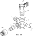
- Fig. 11 is a simplified exploded view illustration of a stopcock constructed and operative in accordance with still another embodiment not forming part of the present invention.
- the stopcock comprises a housing element 100, which is preferably identical in all respects to housing element 100 which is illustrated and described with respect to Figs. 2A - 3B .
- the housing element 100 includes a main tubular portion 102 and three side ports, designated by reference numerals 104, 106 and 108 respectively.
- a handle element 310 in accordance with still another embodiment is arranged to be seated within main tubular portion 102 of housing element 100. It is also noted that a similar elastomeric element 114 and cap 116 are adapted to be seated within port 106 of the housing element 100, in a similar manner as described with respect to Figs. 1 - 3B .
- Figs. 12A - 13B are simplified pictorial illustrations of the handle element 310 forming part of the stopcock of Fig. 11 and to Figs. 14A - 14C , which are sectional illustrations thereof.
- Shaft portion 330 is generally symmetrical about a shaft axis 342 and has a slightly conical outer surface 344, typically having an angle ⁇ (as seen particularly in Fig. 13A ) of 3-4 degrees, which corresponds to the slightly conical configuration of central bore 119 for rotatable sealing engagement therewith.
- shaft portion 330 is typically formed with mutually sealed top and bottom cylindrical recesses 346 and 348, which are sealingly separated by a divider 350.
- At least one fluid flow passage is provided through handle element 310.
- the fluid flow rate is increased by at least 25%.
- the fluid flow rate is increased by at least 50%.
- the fluid flow rate is increased from 300ml/min to 600ml/min.
- the two fluid flow passages are interconnected in some of the mutual relative positions of the handle element 310 and the housing element 100 and that the two fluid flow passages are isolated in other of the mutual relative positions of the handle element 310 and the housing element 100 as described in detail hereinbelow.
- a side-to-side extending bore 352 Disposed generally between recesses 346 and 348 and sealed therefrom is a side-to-side extending bore 352, selectably defining a first fluid flow passageway between two of the selectable ones of side ports 104, 106 and 108 depending on the rotational orientation of the handle element 310 relative to the housing element 100. It is appreciated that in this particular embodiment, the side-to-side extending bore 352 has a semi-circular cross-section, however it is appreciated that bore 352 can alternatively have any other shape, such as circular, rectangular or other which provides the desired fluid flow rate.
- a partially peripherally-extending recess 353 selectably defining a second fluid flow passageway between selectable ones of side ports 104, 106 and 108 depending on the rotational orientation of the handle element 310 relative to the housing element 100.
- a fluid flow guide 354 Preferably extending radially and partially bifurcating the recess 353 is a fluid flow guide 354, which is configured for directing the flow of liquid between any of ports 104 and 108 through the second fluid flow passageway defined by recess 353 into the internal volume 121 of port 106 for flushing thereof, when the handle element 310 is suitably positioned.
- the radially outward facing edge 356 of fluid flow guide 354 extends preferably towards the inner surface of central bore 119 but is slightly spaced therefrom in order to provide minimal fluid flow passage there past when fluid flow guide 354 is not located opposite a port as shown and described in detail hereinbelow.
- the fluid flow guide 354 may alternatively have many other shapes such that the radially outward facing edge 356 of fluid flow guide 354 is formed with a suitably tapered configuration in order to prevent liquid flow there past when fluid flow guide 354 is not located opposite any of ports 104, 106 and 108.
- fluid communication between opposite ends of bore 352 occurs in parallel to fluid communication along recess 353 at least in part of the mutual relative positions of the handle element 310 and housing element 100.
- Fluid flow guide 354 directs the flow of liquid between ports 104 and 108 through recess 353 and into the internal volume 121 of port 106 for flushing thereof, when the handle element 310 is suitably positioned. Simultaneously, fluid flow is directed between ports 104 and 108 through bore 352, thereby increasing the fluid flow rate through the stopcock of Fig. 11 .
- the fluid flow guide 354 in accordance with an embodiment is formed as a fin having one generally concave wall surface 360 and another generally convex wall surface 362 connected with a generally straight wall surface 364.
- the straight wall surface 364 and the concave wall surface 360 are joined at the radially outward facing edge 356, which is adapted to extend to the vicinity of the inner surface of inner bore 119 of housing element 100.
- Both the convex wall surface 362 and the concave wall surface 360 extend from the radially outward facing edge 356 to the vicinity of bore 352 and typically extend along a relatively minor longitudinal extent of bore 352.
- Fig. 15 is a simplified exploded view illustration of a stopcock constructed and operative in accordance with an embodiment of the present invention.
- the stopcock comprises a housing element 100, which is preferably identical in all respects to housing element 100 which is illustrated and described with respect to Figs. 2A - 3B .
- the housing element 100 includes a main tubular portion 102 and three side ports, designated by reference numerals 104, 106 and 108 respectively.
- a handle element 410 in accordance with still another embodiment of the present invention is arranged to be seated within main tubular portion 102 of housing element 100. It is also noted that a similar elastomeric element 114 and cap 116 are adapted to be seated within port 106 of the housing element 100, in a similar manner as described with respect to Figs. 1 - 3B .
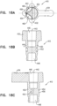
- FIGS. 16A - 17B are simplified pictorial illustrations of the handle element 410 forming part of the stopcock of Fig. 15 and to Figs. 18A - 18C , which are sectional illustrations thereof.
- Shaft portion 430 is generally symmetrical about a shaft axis 442 and has a slightly conical outer surface 444, typically having an angle ⁇ (as seen particularly in Fig. 17A ) of 3-4 degrees, which corresponds to the slightly conical configuration of central bore 119 for rotatable sealing engagement therewith.
- shaft portion 430 is typically formed with mutually sealed top and bottom cylindrical recesses 446 and 448, which are sealingly separated by a divider 450.
- two fluid flow passages are provided through handle element 410. This enables an increase of a fluid flow rate through the handle element 410.
- the fluid flow rate is increased by at least 25%.
- the fluid flow rate is increased by at least 50%.
- the fluid flow rate is increased from 300ml/min to 600ml/min.
- the two fluid flow passages are interconnected in some of the mutual relative positions of the handle element 410 and the housing element 100 and that the two fluid flow passages are isolated in other of the mutual relative positions of the handle element 410 and the housing element 100 as described in detail hereinbelow.
- a side-to-side extending bore 452 Disposed generally between recesses 446 and 448 and sealed therefrom is a side-to-side extending bore 452, selectably defining a first fluid flow passageway between two of the selectable ones of side ports 104, 106 and 108 depending on the rotational orientation of the handle element 410 relative to the housing element 100.
- the side-to-side extending bore 452 has an obround cross-section, however it is appreciated that bore 452 can alternatively have any other shape, such as circular, rectangular or other which provides the desired fluid flow rate.
- a fluid flow guide 454 Preferably extending radially and partially bifurcating the recess 453 is a fluid flow guide 454, which is configured for directing the flow of liquid between any of ports 104 and 108 through the second fluid flow passageway defined by recess 453 into the internal volume 121 of port 106 for flushing thereof, when the handle element 410 is suitably positioned.
- the radially outward facing edge 456 of fluid flow guide 454 extends preferably towards the inner surface of central bore 119 but is slightly spaced therefrom in order to provide minimal fluid flow passage there past when fluid flow guide 454 is not located opposite a port as shown and described in detail hereinbelow.
- the fluid flow guide 454 may alternatively have many other shapes such that the radially outward facing edge 456 of fluid flow guide 454 is formed with a suitably tapered configuration in order to prevent liquid flow there past when fluid flow guide 454 is not located opposite any of ports 104, 106 and 108.
- fluid communication between opposite ends of bore 452 occurs in parallel to fluid communication along recess 453, at least in some operating positions of the stopcock of Fig. 15 at least in some of the mutual relative positions of the handle element 410 and housing element 100.
- Fluid flow guide 454 directs the flow of liquid between ports 104 and 108 through recess 453 and into the internal volume 121 of port 106 for flushing thereof, when the handle element 410 is suitably positioned. Simultaneously, fluid flow is directed between ports 104 and 108 through bore 452, thereby increasing the fluid flow rate through the stopcock of Fig. 15 .
- the fluid flow guide 454 in accordance with an embodiment of the present invention is formed as a wedge having two symmetric generally concave wall surfaces 460.
- the concave wall surfaces 460 are joined at the radially outward facing edge 456, which is adapted to extend to the vicinity of the inner surface of inner bore 119 of housing element 100.
- the concave wall surfaces 460 extend from the radially outward facing edge 456 to the vicinity of bore 452 and typically extend along a relatively major longitudinal extent of bore 452, preferably along the entire longitudinal extent of bore 452.
- concave wall surfaces 460 extend from the outward facing edge 456 towards the inner surface of the central bore 119 of main tubular portion 102 of the housing element 100, as seen and described in more detail hereinbelow.
- bore 452 is generally spaced from recess 453 by fluid flow guide 454, therefore the first fluid flow passage is generally isolated from the second fluid flow passage at least in some of the mutual relative positions of the handle element 410 and housing element 100.
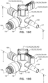
- Figs. 19A, 19B , 19C and 19D are simplified assembled pictorial illustrations of the stopcock of Fig. 1 in four operative orientations and to Figs. 20A, 20B , 20C and 20D , which are sectional illustrations of the stopcock having the handle shown in Figs. 4A - 6C , taken along section lines A - A, B - B, C - C and D - D in Figs. 19A, 19B , 19C and 19D respectively.
- port 104 is preferably connected to a patient
- port 108 is preferably connected through an IV set to an infusion bag
- port 106 is preferably adapted for insertion of a medical instrument, such as a syringe thereinto.
- Figs. 19A and 20A illustrate a first operating position of the stopcock of Fig. 1 , which is typically employed for blood pressure monitoring by means of a pressure transducer, where there should be no contact of fluid with the elastomeric element 114.
- the handle element 110 is rotatably disposed within the main tubular portion 102 of the housing element 100, such that finger engageable protrusion 134 is aligned with port 106 of the housing element 100 and extends along an axis, which is parallel to axis 118.
- FIG. 20A there is a fluid communication between ports 104 and 108 through first fluid flow passage defined by side-to-side extending bore 152, as indicated by an arrow 500.
- Liquid communication from port 108 to port 104 through second fluid flow passage, defined by recess 153, past fluid flow guide 154 is prevented, because it is blocked by fluid flow guide 154, whose edge 156 sealingly engages an inner facing wall of central bore 119 of housing element 100.
- This orientation may be utilized to provide fluid flow between ports 104 and 108 only.
- first fluid flow passage allows liquid communication between port 104 and 108 and liquid communication along the second fluid flow passage, particularly along recess 153, in this orientation is preferably blocked.
- the fluid flow guide 154 can extend toward the inner facing wall of central bore 119 of housing element 100, whereas the edge 156 is slightly spaced therefrom in order to allow minimal fluid flow passage through the second fluid flow passage, along recess 153 and around fluid flow guide 154.
- liquid communication between port 104 and 108 through side-to-side bore 152 is sufficient for the purpose of pressure monitoring, while avoiding dampening of the signal, which could have occurred if the fluid would come in contact with elastomeric element 114.
- Figs. 19B and 20B illustrate a second operating position of the stopcock of Fig. 1 , where the handle element 110 is rotatably disposed within the main tubular portion 102 of the housing element 100, such that finger engageable protrusion 134 is aligned with port 108 of the housing element 100 and extends along an axis, which is parallel to axis 117.
- Figs. 19B and 20B illustrate a second operating position of the stopcock of Fig. 1 , which is typically employed for drawing blood or other fluids from the patient.
- the user typically connects a syringe to port 106, such that the luer of the syringe penetrates elastomeric element 114, such that the luer of the syringe communicates with an internal volume 502 of the elastomeric element 114, and draws blood from the patient through port 104, via bore 152 as indicated by an arrow 504 and via recess 153 as indicated by an arrow 506, through port 106 to the syringe.
- this operating position may also be used for supplying a medicament to the patient when port 108 is closed, in a flow direction opposite to that indicated by arrows 504 and 506.
- a portion of fluid from port 104 enters the first fluid flow passage, defined by side-to-side bore 152.
- This portion of fluid flows along a portion of the second fluid flow passage, specifically along one side of the flat wall 160 and thereafter first concave portion 162 of the fluid flow guide 154, the fluid is then directed into side-to-side bore 152 and then in turn flows along side-to-side bore 152 into cylindrical bore 122 of port 106 and through the interior volume 502 of the elastomeric element 114 into the syringe, which is connected to port 106.
- the remaining portion of fluid from port 104 enters the second fluid flow passage, which is preferably defined by the circumferential recess 153, such that in this operating position, the fluid flows along another side of flat wall 160 and thereafter along the second concave portion 162 of the fluid flow guide 154, which effectively directs the flow into cylindrical bore 122 of port 106, and further into the internal volume 502 of the elastomeric element 114 and into the syringe, which is connected to port 106.
- the second fluid flow passage has various configurations in accordance with the configuration of the fluid flow guide 154.
- the fluid flows along the flat wall 160 and the concave portions 162 of the fluid flow guide 154, a smooth laminar flow of liquid is provided and singularity points along the fluid flow passage are prevented.
- fluid flow rate increase is enabled by provision of the first fluid flow passage via bore 152 in addition to the second fluid flow passage defined by recess 153, while flushing characteristics of the stopcock due to the presence of fluid flow guides 154 and 128 are not compromised.
- Figs. 19C and 20C illustrate a third operating position of the stopcock of Fig. 1 , where the handle element 110 is rotatably disposed within the main tubular portion 102 of the housing element 100, such that finger engageable protrusion 134 extends in a direction opposite to port 106 of the housing element 100 and extends along an axis, which is parallel to axis 118.
- Figs. 19C and 20C illustrate a third operating position of the stopcock of Fig. 1 , which is typically employed for supplying a liquid to the patient from port 108 to port 104.
- Liquid flows via the first fluid flow passage from port 108 via bore 152 and into port 104, as indicated by an arrow 508.
- Liquid also simultaneously flows via the second fluid flow passage from port 108 via recess 153, around fluid flow guide 154 into interior volume 121 of port 106 and thereafter around fluid flow guide 128 into internal volume 502 of the elastomeric element 114, thereby flushing residual liquid therefrom, and flowing further around fluid flow guides 128 and 154 into port 104 and to the patient, as indicated by an arrow 510.
- the remaining portion of the fluid from port 108 enters the second fluid flow passage, which is preferably defined by the circumferential recess 153, such that in this operating position, the fluid flows along the first concave portion 162 and thereafter along one side of flat wall 160 of the fluid flow guide 154, which effectively directs the entire fluid flow that enters the second fluid flow passage into cylindrical bore 122 of port 106.
- the fluid is directed along one side of the fluid flow guide 128 into the internal volume 502 of the elastomeric element 114 and while flushing this internal volume, the fluid is directed along the other side of fluid flow guide 128, thereafter along the other side of flat wall 160 and the second concave portion 162 of the fluid flow guide 154 and eventually into port 104, as indicated by arrow 510.
- the second fluid flow passage has various configurations in accordance with the configuration of the fluid flow guide 154.
- the fluid flows along the flat wall 160 and the concave portions 162 of the fluid flow guide 154, a smooth laminar flow of liquid is provided and singularity points along the fluid flow passage are prevented.
- fluid flow guides 154 and 128 generally overcomes problems of the presence of residual liquids remaining in the internal volume 121 of port 106 as well as in internal volume 502 of the elastomeric element 114. This is important in various therapeutic situations. For example when blood is drawn from the patient through port 106, there remains residual blood in the internal volume 121 of port 106 and the internal volume 502 of the elastomeric element 114. This blood, if left in internal volumes 121 and 502 for a period of time, can clot and thus become dangerous if delivered to the patient. In addition, the coagulated blood could occlude the liquid passageway extending through port 106. Various infections could possibly arise as a result of the retained blood.
- This feature is also useful when a medicament is supplied to a patient through port 106. If a portion of the medicament remains in the internal volumes 121 of port 106 and 502 of the elastomeric element 114, the dosage of the medicament that the patient receives is less than the intended dosage by an amount which cannot be readily ascertained. In addition, this residual medicament might be inadvertently supplied to the patient during a subsequent use of the stopcock, which could cause harm to the patient.
- the present disclosure invention provides for automatic flushing of the liquid, such as blood or medicament from the internal volumes 121 and 502 and typically returning it to the patient without requiring the use of extra syringes and the opening of the medical set to the atmosphere, thereby increasing the chance of contamination.
- first fluid flow passage through side-to-side bore 152 is provided for increasing the flow rate through the stopcock of Fig. 1 while maintaining the flushing feature of volumes 121 and 502 via the second fluid flow passage.
- Figs. 19D and 20D illustrate a fourth operating position of the stopcock of Fig. 1 , where the handle element 110 is rotatably disposed within the main tubular portion 102 of the housing element 100, such that finger engageable protrusion 134 is aligned with port 104 of the housing element 100 and extends along an axis, which is parallel to axis 117.
- Figs. 19D and 20D illustrate a fourth operating position of the stopcock of Fig. 1 , which may be used for flushing the IV set upstream of the stopcock, when port 106 is open to the atmosphere as by insertion of a male luer connector, such as a syringe tip (not shown), into the elastomeric element 114 of the valve thereof.
- a male luer connector such as a syringe tip (not shown)
- the insertion of the male luer connector activates the flow of liquid from port 108 via the first fluid flow through bore 152 and into port 106, as indicated by an arrow 512.
- Liquid also simultaneously flows via the second fluid flow passage from port 108 via recess 153, around fluid flow guide 154 into interior volume 121 of port 106 and thereafter around fluid flow guide 128 into internal volume 502 of the elastomeric element 114, flushing residual liquid therefrom, via port 106 to the IV line, as indicated by an arrow 514.
- a portion of fluid from port 108 enters the first fluid flow passage, defined by side-to-side bore 152.
- This portion of fluid flows along a portion of the second fluid flow passage, specifically along one side of the flat wall 160 and thereafter first concave portion 162 of the fluid flow guide 154, the fluid is then directed into side-to-side bore 152 and then in turn flows along side-to-side bore 152 into cylindrical bore 122 of port 106 and through the interior volume 502 of the elastomeric element 114 into the syringe, which is connected to port 106.
- the remaining portion of fluid from port 108 enters the second fluid flow passage, which is preferably defined by the circumferential recess 153, such that in this operating position, the fluid flows along another side of flat wall 160 and thereafter the second concave portion 162 of the fluid flow guide 154, which effectively directs the flow into cylindrical bore 122 of port 106, and further into the internal volume 502 of the elastomeric element 114 and into the syringe, which is connected to port 106.
- the second fluid flow passage has various configurations in accordance with the configuration of the fluid flow guide 154.
- the fluid flows along the flat wall 160 and the concave portions 162 of the fluid flow guide 154, a smooth laminar flow of liquid is provided and singularity points along the fluid flow passage are prevented.
- this operating position may be employed for pushing liquid via the side port 106, through port 108, in a direction opposite arrows 512 and 514, for uses such as mixing liquid in the pressure bag.
- fluid flow rate increase is enabled by provision of the first fluid flow passage via bore 152 in addition to the second fluid flow passage defined by recess 153, while flushing characteristics of the stopcock due to the presence of fluid flow guides 154 and 128 are not compromised.
- Figs. 19A, 19B , 19C and 19D are simplified assembled pictorial illustrations of the stopcock of Fig. 7 in four operative orientations and to Figs. 21A, 21B , 21C and 21D , which are sectional illustrations of the stopcock having the handle shown in Figs. 8A - 10C , taken along section lines A - A, B - B, C - C and D - D in Figs. 19A, 19B , 19C and 19D respectively.
- Figs. 19A and 21A illustrate a first operating position of the stopcock of Fig. 7 , which is typically employed for blood pressure monitoring by means of a pressure transducer, where there should be no contact of fluid with the elastomeric element 114.
- the handle element 210 is rotatably disposed within the main tubular portion 102 of the housing element 100, such that finger engageable protrusion 234 is aligned with port 106 of the housing element 100 and extends along an axis, which is parallel to axis 118.
- FIG. 21A there is a fluid communication between ports 104 and 108 through first fluid flow passage defined by side-to-side extending bore 252, as indicated by an arrow 600.
- Liquid communication from port 108 to port 104 through second fluid flow passage, defined by recess 253, past fluid flow guide 254 is prevented, because it is blocked by fluid flow guide 254, whose edge 256 sealingly engages an inner facing wall of central bore 119 of housing element 100.
- This orientation may be utilized to provide fluid flow between ports 104 and 108 only.
- first fluid flow passage allows liquid communication between port 104 and 108 and liquid communication along the second fluid flow passage, particularly along recess 253, in this orientation is preferably blocked.
- the fluid flow guide 254 can extend toward the inner facing wall of central bore 119 of housing element 100, whereas the edge 256 is slightly spaced therefrom in order to allow minimal fluid flow passage through the second fluid flow passage, along recess 253 and around fluid flow guide 254.
- liquid communication between port 104 and 108 through side-to-side bore 252 is sufficient for the purpose of pressure monitoring, while avoiding dampening of the signal, which could have occurred if the fluid would come in contact with elastomeric element 114.
- Figs. 19B and 20B illustrate a second operating position of the stopcock of Fig. 7 , where the handle element 210 is rotatably disposed within the main tubular portion 102 of the housing element 100, such that finger engageable protrusion 234 is aligned with port 108 of the housing element 100 and extends along an axis, which is parallel to axis 117.
- Figs. 19B and 21B illustrate a second operating position of the stopcock of Fig. 7 , which is typically employed for drawing blood or other fluids from the patient.
- the user typically connects a syringe to port 106, such that the luer of the syringe penetrates elastomeric element 114, such that the luer of the syringe communicates with an internal volume 502 of the elastomeric element 114, and draws blood from the patient through port 104, via bore 252 as indicated by an arrow 604 and via recess 253 as indicated by an arrow 606, through port 106 to the syringe.
- this operating position may also be used for supplying a medicament to the patient when port 108 is closed, in a flow direction opposite to that indicated by arrows 604 and 606.
- a portion of fluid from port 104 enters the first fluid flow passage, defined by side-to-side bore 252.
- This portion of fluid flows along a portion of the second fluid flow passage, specifically along inclined wall surface 258 of the fluid flow guide 254, the fluid is then directed into side-to-side bore 252 and then in turn flows along side-to-side bore 252 into cylindrical bore 122 of port 106 and through the interior volume 502 of the elastomeric element 114 into the syringe, which is connected to port 106.
- the remaining portion of fluid from port 104 enters the second fluid flow passage, which is preferably defined by the circumferential recess 253, such that in this operating position, the fluid flows along concave wall surface 260 of the fluid flow guide 254, which effectively directs the flow into cylindrical bore 122 of port 106, and further into the internal volume 502 of the elastomeric element 114 and into the syringe, which is connected to port 106.
- the second fluid flow passage has various configurations in accordance with the configuration of the fluid flow guide 254.
- the fluid flows along inclined wall surface 258 of the fluid flow guide 254, a smooth laminar flow of liquid is provided and singularity points along the fluid flow passage are prevented.
- fluid flow rate increase is enabled by provision of the first fluid flow passage via bore 252 in addition to the second fluid flow passage defined by recess 253, while flushing characteristics of the stopcock due to the presence of fluid flow guides 254 and 128 are not compromised.
- Figs. 19C and 21C illustrate a third operating position of the stopcock of Fig. 7 , where the handle element 210 is rotatably disposed within the main tubular portion 102 of the housing element 100, such that finger engageable protrusion 234 extends in a direction opposite to port 106 of the housing element 100 and extends along an axis, which is parallel to axis 118.
- Figs. 19C and 21C illustrate a third operating position of the stopcock of Fig. 7 , which is typically employed for supplying a liquid to the patient from port 108 to port 104.
- Liquid flows via the first fluid flow passage from port 108 via bore 252 and into port 104, as indicated by an arrow 608.
- Liquid also simultaneously flows via the second fluid flow passage from port 108 via recess 253, around fluid flow guide 254 into interior volume 121 of port 106 and thereafter around fluid flow guide 128 into internal volume 502 of the elastomeric element 114, thereby flushing residual liquid therefrom, and flowing further around fluid flow guides 128 and 254 into port 104 and to the patient, as indicated by an arrow 610.
- the remaining portion of the fluid from port 108 enters the second fluid flow passage, which is preferably defined by the circumferential recess 253, such that in this operating position, the fluid flows along concave wall surface 260 of the fluid flow guide 254, which effectively directs the entire fluid flow that enters the second fluid flow passage into cylindrical bore 122 of port 106.
- the fluid is directed along one side of the fluid flow guide 128 into the internal volume 502 of the elastomeric element 114 and while flushing this internal volume, the fluid is directed along the other side of fluid flow guide 128, thereafter along inclined wall surface 258 of the fluid flow guide 254 and eventually into port 104, as indicated by arrow 610.
- the second fluid flow passage has various configurations in accordance with the configuration of the fluid flow guide 254.
- the fluid flows along the concave wall surface 260 and along inclined wall surface 158 of the fluid flow guide 254, a smooth laminar flow of liquid is provided and singularity points along the fluid flow passage are prevented.
- the provision of fluid flow guides 254 and 128 generally overcomes problems of the presence of residual liquids remaining in the internal volume 121 of port 106 as well as in internal volume 502 of the elastomeric element 114. This is important in various therapeutic situations. For example, when blood is drawn from the patient through port 106, there remains residual blood in the internal volume 121 of port 106 and the internal volume 502 of the elastomeric element 114. This blood, if left in internal volumes 121 and 502 for a period of time, can clot and thus become dangerous if delivered to the patient. In addition, the coagulated blood could occlude the liquid passageway extending through port 106. Various infections could possibly arise as a result of the retained blood.
- This feature is also useful when a medicament is supplied to a patient through port 106. If a portion of the medicament remains in the internal volumes 121 of port 106 and 502 of the elastomeric element 114, the dosage of the medicament that the patient receives is less than the intended dosage by an amount which cannot be readily ascertained. In addition, this residual medicament might be inadvertently supplied to the patient during a subsequent use of the stopcock, which could cause harm to the patient.
- the present invention provides for automatic flushing of the liquid, such as blood or medicament from the internal volumes 121 and 502 and typically returning it to the patient without requiring the use of extra syringes and the opening of the medical set to the atmosphere, thereby increasing the chance of contamination.
- first fluid flow passage through side-to-side bore 252 is provided for increasing the flow rate through the stopcock of Fig. 7 while maintaining the flushing feature of volumes 121 and 502 via the second fluid flow passage.
- Figs. 19D and 21D illustrate a fourth operating position of the stopcock of Fig. 7 , where the handle element 210 is rotatably disposed within the main tubular portion 102 of the housing element 100, such that finger engageable protrusion 234 is aligned with port 104 of the housing element 100 and extends along an axis, which is parallel to axis 117.
- Figs. 19D and 21D illustrate a fourth operating position of the stopcock of Fig. 7 , which may be used for flushing the IV set upstream of the stopcock, when port 106 is open to the atmosphere as by insertion of a male luer connector, such as a syringe tip (not shown), into the elastomeric element 114 of the valve thereof.
- a male luer connector such as a syringe tip (not shown)
- the insertion of the male luer connector activates the flow of liquid from port 108 via the first fluid flow through bore 252 and into port 106, as indicated by an arrow 612.
- Liquid also simultaneously flows via the second fluid flow passage from port 108 via recess 253, around fluid flow guide 254 into interior volume 121 of port 106 and thereafter around fluid flow guide 128 into internal volume 502 of the elastomeric element 114, flushing residual liquid therefrom, via port 106 to the IV line, as indicated by an arrow 614.
- a portion of fluid from port 108 enters the first fluid flow passage, defined by side-to-side bore 252.
- This portion of fluid flows along a portion of the second fluid flow passage, specifically along concave wall surface 260 of the fluid flow guide 254, the fluid is then directed into side-to-side bore 252 and then in turn flows along side-to-side bore 252 into cylindrical bore 122 of port 106 and through the interior volume 502 of the elastomeric element 114 into the syringe, which is connected to port 106.
- the remaining portion of fluid from port 108 enters the second fluid flow passage, which is preferably defined by the circumferential recess 253, such that in this operating position, the fluid flows along inclined wall surface 258 of the fluid flow guide 254, which effectively directs the flow into cylindrical bore 122 of port 106, and further into the internal volume 502 of the elastomeric element 114 and into the syringe, which is connected to port 106.
- the second fluid flow passage has various configurations in accordance with the configuration of the fluid flow guide 254.
- a smooth laminar flow of liquid is provided and singularity points along the fluid flow passage are prevented.
- this operating position may be employed for pushing liquid via the side port 106, through port 108, in a direction opposite arrows 612 and 614, for uses such as mixing liquid in the pressure bag.
- fluid flow rate increase is enabled by provision of the first fluid flow passage via bore 252 in addition to the second fluid flow passage defined by recess 253, while flushing characteristics of the stopcock due to the presence of fluid flow guides 254 and 128 are not compromised.
- Figs. 19A, 19B , 19C and 19D are simplified assembled pictorial illustrations of the stopcock of Fig. 11 in four operative orientations and to Figs. 22A, 22B , 22C and 22D , which are sectional illustrations of the stopcock having the handle shown in Figs. 12A - 14C , taken along section lines A - A, B - B, C - C and D - D in Figs. 19A, 19B , 19C and 19D respectively.
- Figs. 19A and 22A illustrate a first operating position of the stopcock of Fig. 11 , which is typically employed for blood pressure monitoring by means of a pressure transducer, where there should be no contact of fluid with the elastomeric element 114.
- the handle element 310 is rotatably disposed within the main tubular portion 102 of the housing element 100, such that finger engageable protrusion 334 is aligned with port 106 of the housing element 100 and extends along an axis, which is parallel to axis 118.
- FIG. 22A there is a fluid communication between ports 104 and 108 through first fluid flow passage defined by side-to-side extending bore 352, as indicated by an arrow 700.
- Liquid communication from port 108 to port 104 through second fluid flow passage, defined by recess 353, past fluid flow guide 354 is prevented, because it is blocked by fluid flow guide 354, whose edge 356 sealingly engages an inner facing wall of central bore 119 of housing element 100.
- This orientation may be utilized to provide fluid flow between ports 104 and 108 only.
- first fluid flow passage allows liquid communication between port 104 and 108 and liquid communication along the second fluid flow passage, particularly along recess 353, in this orientation is preferably blocked.
- the fluid flow guide 354 can extend toward the inner facing wall of central bore 119 of housing element 100, whereas the edge 356 is slightly spaced therefrom in order to allow minimal fluid flow passage through the second fluid flow passage, along recess 353 and around fluid flow guide 354.
- liquid communication between port 104 and 108 through side-to-side bore 352 is sufficient for the purpose of pressure monitoring, while avoiding dampening of the signal, which could have occurred if the fluid would come in contact with elastomeric element 114.
- Figs. 19B and 22B illustrate a second operating position of the stopcock of Fig. 11 , where the handle element 310 is rotatably disposed within the main tubular portion 102 of the housing element 100, such that finger engageable protrusion 334 is aligned with port 108 of the housing element 100 and extends along an axis, which is parallel to axis 117.
- Figs. 19B and 22B illustrate a second operating position of the stopcock of Fig. 11 , which is typically employed for drawing blood or other fluids from the patient.
- the user typically connects a syringe to port 106, such that the luer of the syringe penetrates elastomeric element 114, such that the luer of the syringe communicates with an internal volume 502 of the elastomeric element 114, and draws blood from the patient through port 104, via bore 352 as indicated by an arrow 704 and via recess 353 as indicated by an arrow 706, through port 106 to the syringe.
- this operating position may also be used for supplying a medicament to the patient when port 108 is closed, in a flow direction opposite to that indicated by arrows 704 and 706.
- a portion of fluid from port 104 enters the first fluid flow passage, defined by side-to-side bore 352.
- This portion of fluid flows along a portion of the second fluid flow passage, specifically along straight wall surface 364 and thereafter convex wall surface 362 of the fluid flow guide 354, the fluid is then directed into side-to-side bore 352 and then in turn flows along side-to-side bore 352 into cylindrical bore 122 of port 106 and through the interior volume 502 of the elastomeric element 114 into the syringe, which is connected to port 106.
- the remaining portion of fluid from port 104 enters the second fluid flow passage, which is preferably defined by the circumferential recess 353, such that in this operating position, the fluid flows along concave wall surface 360 of the fluid flow guide 354, which effectively directs the flow into cylindrical bore 122 of port 106, and further into the internal volume 502 of the elastomeric element 114 and into the syringe, which is connected to port 106.
- the second fluid flow passage has various configurations in accordance with the configuration of the fluid flow guide 354.
- the fluid flows along straight wall surface 364 and thereafter convex wall surface 362 of the fluid flow guide 354, a smooth laminar flow of liquid is provided and singularity points along the fluid flow passage are prevented.
- fluid flow rate increase is enabled by provision of the first fluid flow passage via bore 352 in addition to the second fluid flow passage defined by recess 353, while flushing characteristics of the stopcock due to the presence of fluid flow guides 354 and 128 are not compromised.
- Figs. 19C and 22C illustrate a third operating position of the stopcock of Fig. 11 , where the handle element 310 is rotatably disposed within the main tubular portion 102 of the housing element 100, such that finger engageable protrusion 334 extends in a direction opposite to port 106 of the housing element 100 and extends along an axis, which is parallel to axis 118.
- Figs. 19C and 22C illustrate a third operating position of the stopcock of Fig. 11 , which is typically employed for supplying a liquid to the patient from port 108 to port 104.
- Liquid flows via the first fluid flow passage from port 108 via bore 352 and into port 104, as indicated by an arrow 708.
- Liquid also simultaneously flows via the second fluid flow passage from port 108 via recess 353, around fluid flow guide 354 into interior volume 121 of port 106 and thereafter around fluid flow guide 128 into internal volume 502 of the elastomeric element 114, thereby flushing residual liquid therefrom, and flowing further around fluid flow guides 128 and 354 into port 104 and to the patient, as indicated by an arrow 710.
- the remaining portion of the fluid from port 108 enters the second fluid flow passage, which is preferably defined by the circumferential recess 353, such that in this operating position, the fluid flows along concave wall surface 360 of the fluid flow guide 354, which effectively directs the entire fluid flow that enters the second fluid flow passage into cylindrical bore 122 of port 106.
- the fluid is directed along one side of the fluid flow guide 128 into the internal volume 502 of the elastomeric element 114 and while flushing this internal volume, the fluid is directed along the other side of fluid flow guide 128, thereafter along straight wall surface 364 and convex wall surface 362 of the fluid flow guide 354 and eventually into port 104, as indicated by arrow 710.
- the second fluid flow passage has various configurations in accordance with the configuration of the fluid flow guide 354.
- the fluid flows along concave wall surface 360 and then straight wall surface 364 and thereafter convex wall surface 362 of the fluid flow guide 354, a smooth laminar flow of liquid is provided and singularity points along the fluid flow passage are prevented.
- the provision of fluid flow guides 354 and 128 generally overcomes problems of the presence of residual liquids remaining in the internal volume 121 of port 106 as well as in internal volume 502 of the elastomeric element 114. This is important in various therapeutic situations. For example, when blood is drawn from the patient through port 106, there remains residual blood in the internal volume 121 of port 106 and the internal volume 502 of the elastomeric element 114. This blood, if left in internal volumes 121 and 502 for a period of time, can clot and thus become dangerous if delivered to the patient. In addition, the coagulated blood could occlude the liquid passageway extending through port 106. Various infections could possibly arise as a result of the retained blood.
- This feature is also useful when a medicament is supplied to a patient through port 106. If a portion of the medicament remains in the internal volumes 121 of port 106 and 502 of the elastomeric element 114, the dosage of the medicament that the patient receives is less than the intended dosage by an amount which cannot be readily ascertained. In addition, this residual medicament might be inadvertently supplied to the patient during a subsequent use of the stopcock, which could cause harm to the patient.
- the present invention provides for automatic flushing of the liquid, such as blood or medicament from the internal volumes 121 and 502 and typically returning it to the patient without requiring the use of extra syringes and the opening of the medical set to the atmosphere, thereby increasing the chance of contamination.
- first fluid flow passage through side-to-side bore 352 is provided for increasing the flow rate through the stopcock of Fig. 11 while maintaining the flushing feature of volumes 121 and 502 via the second fluid flow passage.
- Figs. 19D and 22D illustrate a fourth operating position of the stopcock of Fig. 11 , where the handle element 310 is rotatably disposed within the main tubular portion 102 of the housing element 100, such that finger engageable protrusion 334 is aligned with port 104 of the housing element 100 and extends along an axis, which is parallel to axis 117.
- Figs. 19D and 22D illustrate a fourth operating position of the stopcock of Fig. 11 , which may be used for flushing the IV set upstream of the stopcock, when port 106 is open to the atmosphere as by insertion of a male luer connector, such as a syringe tip (not shown), into the elastomeric element 114 of the valve thereof.
- a male luer connector such as a syringe tip (not shown)
- the insertion of the male luer connector activates the flow of liquid from port 108 via the first fluid flow through bore 352 and into port 106, as indicated by an arrow 712.
- Liquid also simultaneously flows via the second fluid flow passage from port 108 via recess 353, around fluid flow guide 354 into interior volume 121 of port 106 and thereafter around fluid flow guide 128 into internal volume 502 of the elastomeric element 114, flushing residual liquid therefrom, via port 106 to the IV line, as indicated by an arrow 714.
- a portion of fluid from port 108 enters the first fluid flow passage, defined by side-to-side bore 352.
- This portion of fluid flows along a portion of the second fluid flow passage, specifically along concave wall surface 360 of the fluid flow guide 354, the fluid is then directed into side-to-side bore 352 and then in turn flows along side-to-side bore 352 into cylindrical bore 122 of port 106 and through the interior volume 502 of the elastomeric element 114 into the syringe, which is connected to port 106.
- the remaining portion of fluid from port 108 enters the second fluid flow passage, which is preferably defined by the circumferential recess 353, such that in this operating position, the fluid flows along straight wall surface 364 and convex wall surface 362 of the fluid flow guide 354, which effectively directs the flow into cylindrical bore 122 of port 106, and further into the internal volume 502 of the elastomeric element 114 and into the syringe, which is connected to port 106.
- the second fluid flow passage has various configurations in accordance with the configuration of the fluid flow guide 354.
- the fluid flows along concave wall surface 360 of the fluid flow guide 354, a smooth laminar flow of liquid is provided and singularity points along the fluid flow passage are prevented.
- this operating position may be employed for pushing liquid via the side port 106, through port 108, in a direction opposite arrows 712 and 714, for uses such as mixing liquid in the pressure bag.
- fluid flow rate increase is enabled by provision of the first fluid flow passage via bore 352 in addition to the second fluid flow passage defined by recess 353, while flushing characteristics of the stopcock due to the presence of fluid flow guides 354 and 128 are not compromised.
- Figs. 19A, 19B , 19C and 19D are simplified assembled pictorial illustrations of the stopcock of Fig. 15 in four operative orientations and to Figs. 23A, 23B , 23C and 23D , which are sectional illustrations of the stopcock having the handle shown in Figs. 16A - 18C , taken along section lines A - A, B - B, C - C and D - D in Figs. 19A, 19B , 19C and 19D respectively.
- Figs. 19A and 23A illustrate a first operating position of the stopcock of Fig. 15 , which is typically employed for blood pressure monitoring by means of a pressure transducer, where there should be no contact of fluid with the elastomeric element 114.
- the handle element 410 is rotatably disposed within the main tubular portion 102 of the housing element 100, such that finger engageable protrusion 434 is aligned with port 106 of the housing element 100 and extends along an axis, which is parallel to axis 118.
- FIG. 23A there is a fluid communication between ports 104 and 108 through first fluid flow passage defined by side-to-side extending bore 452, as indicated by an arrow 800.
- Liquid communication from port 108 to port 104 through second fluid flow passage, defined by recess 453, past fluid flow guide 454 is prevented, because it is blocked by fluid flow guide 454, whose edge 456 sealingly engages an inner facing wall of central bore 119 of housing element 100.
- This orientation may be utilized to provide fluid flow between ports 104 and 108 only.
- first fluid flow passage allows liquid communication between port 104 and 108 and liquid communication along the second fluid flow passage, particularly along recess 453, in this orientation is preferably blocked.
- the fluid flow guide 454 can extend toward the inner facing wall of central bore 119 of housing element 100, whereas the edge 456 is slightly spaced therefrom in order to allow minimal fluid flow passage through the second fluid flow passage, along recess 453 and around fluid flow guide 454.
- liquid communication between port 104 and 108 through side-to-side bore 452 is sufficient for the purpose of pressure monitoring, while avoiding dampening of the signal, which could have occurred if the fluid would come in contact with elastomeric element 114.
- Figs. 19B and 23B illustrate a second operating position of the stopcock of Fig. 15 , where the handle element 410 is rotatably disposed within the main tubular portion 102 of the housing element 100, such that finger engageable protrusion 534 is aligned with port 108 of the housing element 100 and extends along an axis, which is parallel to axis 117.
- Figs. 19B and 23B illustrate a second operating position of the stopcock of Fig. 15 , which is typically employed for drawing blood or other fluids from the patient.
- the user typically connects a syringe to port 106, such that the luer of the syringe penetrates elastomeric element 114, such that the luer of the syringe communicates with an internal volume 502 of the elastomeric element 114, and draws blood from the patient through port 104, via recess 453 as indicated by an arrow 806, through port 106 to the syringe.
- this operating position may also be used for supplying a medicament to the patient when port 108 is closed, in a flow direction opposite to that indicated by arrow 806.
- Figs. 19C and 23C illustrate a third operating position of the stopcock of Fig. 15 , where the handle element 410 is rotatably disposed within the main tubular portion 102 of the housing element 100, such that finger engageable protrusion 434 extends in a direction opposite to port 106 of the housing element 100 and extends along an axis, which is parallel to axis 118.
- Figs. 19C and 23C illustrate a third operating position of the stopcock of Fig. 15 , which is typically employed for supplying a liquid to the patient from port 108 to port 104.
- Liquid flows via the first fluid flow passage from port 108 via bore 452 and into port 104, as indicated by an arrow 808.
- Liquid also simultaneously flows via the second fluid flow passage from port 108 via recess 453, around fluid flow guide 454 into interior volume 121 of port 106 and thereafter around fluid flow guide 128 into internal volume 502 of the elastomeric element 114, thereby flushing residual liquid therefrom, and flowing further around fluid flow guides 128 and 454 into port 104 and to the patient, as indicated by an arrow 810.
- the remaining portion of the fluid from port 108 enters the second fluid flow passage, which is preferably defined by the circumferential recess 453, such that in this operating position, the fluid flows along the first concave wall surface 460 of the fluid flow guide 454, which effectively directs the entire fluid flow that enters the second fluid flow passage into cylindrical bore 122 of port 106.
- the fluid is directed along one side of the fluid flow guide 128 into the internal volume 502 of the elastomeric element 114 and while flushing this internal volume, the fluid is directed along the other side of fluid flow guide 128, thereafter along the second concave wall surface 460 of the fluid flow guide 454 and eventually into port 104, as indicated by arrow 810.
- the second fluid flow passage has various configurations in accordance with the configuration of the fluid flow guide 454.
- the fluid flows along concave wall surfaces 460 of the fluid flow guide 454, a smooth laminar flow of liquid is provided and singularity points along the fluid flow passage are prevented.
- the concave wall surface 460 extends to the vicinity of the inner facing wall of the central bore 119, causes liquid flowing from port 108 to be bifurcated right upon reaching main tubular element 102 of the housing element 100, thus assuring that a significant portion of liquid from port 108 flows into peripherally-extending recess 453, as indicated by arrow 810, and further into interior volume 121 of port 106 and into internal volume 502 of the elastomeric element 114 in order to provide proper flushing of both the internal volume 502 and of the interior volume 121. It is noted that the remaining portion of liquid from port 108 simultaneously flows through side-to-side extending bore 452, as indicated by arrow 808, in this third operating position of the stopcock in order to increase the flow rate of liquid flowing from port 108 to port 104.
- the provision of fluid flow guides 454 and 128 generally overcomes problems of the presence of residual liquids remaining in the internal volume 121 of port 106 as well as in internal volume 502 of the elastomeric element 114. This is important in various therapeutic situations. For example, when blood is drawn from the patient through port 106, there remains residual blood in the internal volume 121 of port 106 and the internal volume 502 of the elastomeric element 114. This blood, if left in internal volumes 121 and 502 for a period of time, can clot and thus become dangerous if delivered to the patient. In addition, the coagulated blood could occlude the liquid passageway extending through port 106. Various infections could possibly arise as a result of the retained blood.
- This feature is also useful when a medicament is supplied to a patient through port 106. If a portion of the medicament remains in the internal volumes 121 of port 106 and 502 of the elastomeric element 114, the dosage of the medicament that the patient receives is less than the intended dosage by an amount which cannot be readily ascertained. In addition, this residual medicament might be inadvertently supplied to the patient during a subsequent use of the stopcock, which could cause harm to the patient.
- the present invention provides for automatic flushing of the liquid, such as blood or medicament from the internal volumes 121 and 502 and typically returning it to the patient without requiring the use of extra syringes and the opening of the medical set to the atmosphere, thereby increasing the chance of contamination.
- first fluid flow passage through side-to-side bore 452 is provided for increasing the flow rate through the stopcock of Fig. 15 while maintaining the flushing feature of volumes 121 and 502 via the second fluid flow passage.
- Figs. 19D and 23D illustrate a fourth operating position of the stopcock of Fig. 15 , where the handle element 410 is rotatably disposed within the main tubular portion 102 of the housing element 100, such that finger engageable protrusion 434 is aligned with port 104 of the housing element 100 and extends along an axis, which is parallel to axis 117.
- Figs. 19D and 23D illustrate a fourth operating position of the stopcock of Fig. 15 , which may be used for flushing the IV set upstream of the stopcock, when port 106 is open to the atmosphere as by insertion of a male luer connector, such as a syringe tip (not shown), into the elastomeric element 114 of the valve thereof.
- the insertion of the male luer connector activates the flow of liquid from port 108 via the the second fluid flow passage through recess 453, around fluid flow guide 354 into interior volume 121 of port 106 and thereafter around fluid flow guide 128 into internal volume 502 of the elastomeric element 114, flushing residual liquid therefrom, via port 106 to the IV line, as indicated by an arrow 814.
- the second fluid flow passage has various configurations in accordance with the configuration of the fluid flow guide 454.
- the fluid flows along concave wall surface 460 of the fluid flow guide 454, a smooth laminar flow of liquid is provided and singularity points along the fluid flow passage are prevented.
- this operating position may be employed for pushing liquid via the side port 106, through port 108, in a direction opposite arrow 814, for uses such as mixing liquid in the pressure bag.
- the stopcock in accordance with embodiments illustrated in Figs. 1 - 23D is operable is an arterial monitoring set.
- the arterial monitoring set generally includes a fluid-filled bag and a tube portion leading to a patient's artery.
- An arterial pressure sensor is coupled in a series along the tube portion and provides a visible output on a conventional monitor. Downstream of arterial pressure sensor there is provided the stopcock of the type described hereinabove with reference to any of Figs. 1 - 23D , including a swabbable valve having an elastomeric element 114.
- Stopcock such as shown and illustrated in Figs. 19A , 20A , 21A , 22A and 23A is preferably used for transferring liquid through an arterial set, including the stopcock, from the bag to the artery of the patient.
- Stopcock such as shown and illustrated in Figs. 19B , 20B , 21B , 22B and 23B , is typically employed for drawing blood or other fluids from the patient, by employing a syringe coupled to the swabbable valve. It is appreciated that this operating position may also be used for supplying medicament to the patient via syringe.
- Stopcock such as shown and illustrated in Figs. 19C , 20C , 21C , 22C and 23C , is typically employed for supplying a liquid to the patient from the arterial set. Liquid flows through the stopcock and flushes the internal volume of the swabbable valve and of the port in which it is located, flushing residual liquid therefrom to the patient.
- Stopcock such as shown and illustrated in Figs. 19D , 20D , 21D , 22D and 23D , is typically employed for flushing the IV set upstream of the stopcock, when port 106 is open to the atmosphere as by insertion of a male luer connector, such as a syringe tip (not shown), into the elastomeric element 114 of the valve thereof.
- a male luer connector such as a syringe tip (not shown)
- a stopcock shown in any of Figs. 1 - 23D in a monitoring set reduces both the risk of contamination and the need for extra covers or plugs and provides for both flushing of the internal volume of the stopcock and the internal volume of the valve and for increasing the fluid flow rate through the stopcock.
- the stopcock is employed in a position such as that shown in Figs. 19A and any of Figs. 20A , 21A , 22A or 22A , where the fluid flows from the arterial line to the patient without making contact with the elastomeric element 114 of the valve.
- the operator places the handle of the stopcock in the operative orientation shown in Figs. 19B and any of Figs. 20B , 21B , 22B or23B, introduces a syringe to the valve, thereby opening it, and draws blood.
- the operator places the handle of the stopcock in the operative orientation shown in Figs. 19C and any of Figs. 20C , 21C , 22C and 23C .
- the flow of liquid in the arterial line flushes the internal volumes of both the valve and the side port of the stopcock and clears the residual blood therefrom.
- stopcock structure shown and described hereinabove may have many advantageous uses in addition to those described specifically hereinabove.
Landscapes
- Health & Medical Sciences (AREA)
- Engineering & Computer Science (AREA)
- General Engineering & Computer Science (AREA)
- Heart & Thoracic Surgery (AREA)
- Life Sciences & Earth Sciences (AREA)
- Mechanical Engineering (AREA)
- Public Health (AREA)
- Veterinary Medicine (AREA)
- Biomedical Technology (AREA)
- Hematology (AREA)
- Animal Behavior & Ethology (AREA)
- General Health & Medical Sciences (AREA)
- Anesthesiology (AREA)
- Vascular Medicine (AREA)
- Physics & Mathematics (AREA)
- Pulmonology (AREA)
- Fluid Mechanics (AREA)
- Medical Informatics (AREA)
- Pathology (AREA)
- Biophysics (AREA)
- Molecular Biology (AREA)
- Surgery (AREA)
- Cardiology (AREA)
- Infusion, Injection, And Reservoir Apparatuses (AREA)
- Multiple-Way Valves (AREA)
- Taps Or Cocks (AREA)
- Lift Valve (AREA)
Description
- The present invention relates to stopcocks generally, and more specifically to swabbable stopcocks.
- Various fluid flow regulators, such as stopcocks, are known in the art. Closed stopcocks typically have a luer activated valve incorporated within one of the stopcock ports for convenient engagement of a medical instrument with the stopcock.
-
DE 10 2015 205517 relates to a medical fluid control device for a medical fluid line system, and discloses a stopcock according to the pre-characterizing portion of appendedindependent claim 1.US9016316B2 - In accordance with the present invention, there is provided a stopcock as defined in appended
independent claim 1. Embodiments of the present invention are defined in appended claims dependent onindependent claim 1. - The present invention seeks to provide an improved closed stopcock.
- In accordance with an embodiment of the present invention, a stopcock comprising a housing element defining a central bore and at least first, second and third ports, and a handle element, which is selectably positionable relative to the housing element, the housing element and the handle element being arrangeable in multiple mutual positions, at least one of the housing element and the handle element defining a first fluid flow passageway communicating between two of said at least first, second and third ports, and a second fluid flow passageway communicating between at least two of the at least first, second and third ports, selection of the ports being in accordance with a relative position of the handle element relative to the housing element; the first fluid flow passageway including a side-to-side extending bore extending through the handle, and the second fluid flow passageway including a fluid flow guide, and a second fluid flow guide extending radially and partially bifurcating one of the at least one of the first, second and third ports, the second fluid flow guide being associated with at least one of the first fluid flow passageway and the second fluid flow passageway, characterized in that said first fluid flow passageway is fluidly isolated from said second fluid flow passageway in at least one of said mutual positions.
- Preferably, the fluid flow guide extends radially towards an inner facing wall of the central bore and partially bifurcates the second fluid flow passageway. Further preferably, the first fluid flow passageway and the second fluid flow passageway are operative simultaneously in at least one of the multiple mutual positions.
- Yet further preferably, the second fluid flow passageway being configured for enabling flushing an internal volume of at least one of the first, second and third ports by a fluid flow which does not flow entirely through the port whose internal volume is being flushed, and the first fluid flow passageway being configured for increasing a fluid flow rate between two of the at least first, second and third ports.
- In accordance with an embodiment of the present invention, the fluid flow guide comprising an outward facing edge which sealingly engages an inner facing wall of the central bore, and when the outward facing edge of the fluid flow guide is not located opposite any of the first, second and third ports, flow of liquid through the second fluid flow passageway is prevented and flow of liquid through the first fluid flow passageway is allowed.
- In accordance with an embodiment of the present invention, the stopcock also comprising at least one valve, which is associated with at least one of the first, second and third ports. Preferably, the valve includes an elastomeric element, and wherein at least one of the first fluid flow passageway and the second fluid flow passageway is configured for providing a fluid flow which is sealed from the elastomeric element when the housing element and the handle element are in another one of the mutual positions.
- Further preferably, both the first fluid flow passageway and the second fluid flow passageway are defined by a shaft portion of the handle element. Still further preferably, the at least one side-to-side extending bore has a semi-circular cross-section. Yet further preferably, the handle element has a partially peripherally-extending recess, selectably defining the second fluid flow passageway, the fluid flow guide extending radially and partially bifurcating the recess.
- In accordance with an embodiment of the present invention, the at least one side-to-side extending bore is spaced from the recess.
- Preferably, the fluid flow rate is increased by at least 25%.
- Preferably, the first fluid flow passageway is fluidly connected with the second fluid flow passageway in other of said at least one of the mutual positions.
- The present invention will be understood and appreciated more fully from the following detailed description, taken in conjunction with the drawings in which:
Fig. 1 is a simplified exploded view illustration of a stopcock constructed and operative in accordance with an embodiment not forming part of the present invention: -
Figs. 2A & 2B are simplified pictorial illustrations of a housing element, which forms part of the stopcock ofFig. 1 taken in two different directions; -
Figs. 3A & 3B are sectional illustrations taken along section lines A - A and B - B inFigs. 2A and 2B , respectively; -
Figs. 4A & 4B are simplified pictorial illustrations of a handle element, which forms part of the stopcock ofFig. 1 taken in two orientations; -
Figs. 5A & 5B are simplified plan view illustrations of the handle element ofFigs. 4A & 4B taken along respective directions A and B inFig. 4A ; -
Figs. 6A, 6B and 6C are sectional illustrations taken along section lines A - A, B - B and C - C inFig. 4B ; -
Fig. 7 is a simplified exploded view illustration of a stopcock constructed and operative in accordance with another embodiment not forming part of the present invention; -
Figs. 8A & 8B are simplified pictorial illustrations of a handle element, which forms part of the stopcock ofFig. 7 taken in two orientations; -
Figs. 9A & 9B are simplified plan view illustrations of the handle element ofFigs. 8A & 8B taken along respective directions A and B inFig. 8A ; -
Figs. 10A, 10B and 10C are sectional illustrations taken along section lines A - A, B - B and C - C inFig. 8B ; -
Fig. 11 is a simplified exploded view illustration of a stopcock constructed and operative in accordance with still another embodiment not forming part of the present invention; -
Figs. 12A & 12B are simplified pictorial illustrations of a handle element, which forms part of the stopcock ofFig. 11 taken in two orientations; -
Figs. 13A & 13B are simplified plan view illustrations of the handle element ofFigs. 12A & 12B taken along respective directions A and B inFig. 12A ; -
Figs. 14A, 14B and 14C are sectional illustrations taken along section lines A - A, B - B and C - C inFig. 12B ; -
Fig. 15 is a simplified exploded view illustration of a stopcock constructed and operative in accordance with an embodiment of the present invention; -
Figs. 16A & 16B are simplified pictorial illustrations of a handle element, which forms part of the stopcock ofFig. 15 taken in two orientations; -
Figs. 17A & 17B are simplified plan view illustrations of the handle element ofFigs. 16A & 16B taken along respective directions A and B inFig. 16A ; -
Figs. 18A, 18B and 18C are sectional illustrations taken along section lines A - A, B - B and C - C inFig. 16B ; -
Figs. 19A, 19B ,19C and 19D are simplified assembled pictorial illustrations of the stopcock ofFig. 1 in four operative orientations; -
Figs. 20A, 20B ,20C and 20D are sectional illustrations of a stopcock having the handle shown inFigs. 4A - 6C , taken along section lines A - A, B - B, C - C and D - D inFigs. 19A, 19B ,19C and 19D respectively; -
Figs. 21A, 21B ,21C and 21D are sectional illustrations of a stopcock having the handle shown inFigs. 8A - 10C , taken along section lines A - A, B-B, C - C and D - D inFigs. 19A, 19B ,19C and 19D respectively; -
Figs. 22A, 22B ,22C and 22D are sectional illustrations of a stopcock having the handle shown inFigs. 12A - 14C , taken along section lines A - A, B-B, C - C and D - D inFigs. 19A, 19B ,19C and 19D respectively; -
Figs. 23A, 23B ,23C and 23D are sectional illustrations of a stopcock having the handle shown inFigs. 16A - 18C , taken along section lines A - A, B - B, C - C and D - D inFigs. 19A, 19B ,19C and 19D respectively. - Reference is now made to
Fig. 1 , which is a simplified exploded view illustration of a stopcock constructed and operative in accordance with an embodiment not forming part of the present invention; - As seen in
Fig. 1 , the stopcock comprises ahousing element 100 including a maintubular portion 102 and three side ports, designated byreference numerals handle element 110 is arranged to be seated within maintubular portion 102 ofhousing element 100. - Reference is now made additionally to
Figs. 2A & 2B , which are simplified pictorial illustrations of thehousing element 100 and toFigs. 3A & 3B , which are sectional illustrations thereof. - As seen in
Figs. 1 - 3B ,tubular portion 102 ofhousing element 100 is generally cylindrical, arranged about anaxis 112, and hasside ports axis 112.First port 104 is preferably a male port which preferably meets luer standard ISO 594-1, whilesecond port 106 is configured for incorporating a normally closed swabbable valve which is configured to receive a male luer andthird port 108 is preferably a female port, which preferably meets luer standard ISO 594-1. Conventional plugs, nuts and covers may be used in association withports -
Port 106 ofhousing element 100 preferably includes a valve employing anelastomeric element 114, held in place by acap 116, which is welded or otherwise fixed tohousing element 100.Elastomeric element 114 andcap 116 are commercially available from Halkey-Roberts Corporation of St. Petersburg, Fla., USA and described in one or more ofU.S. Pat. Nos. 6,651,956 ;6,089,541 and6,036,171 . Alternatively, valves and valve elements commercially available from other sources such as Becton-Dickinson, Cardinal, Medegen and Filtertek may be employed. -
Ports longitudinal axis 117 andport 106 is preferably arranged alongaxis 118, which extends generally perpendicularly toaxis 117. -
Tubular portion 102 includes acentral bore 119 having a slightly conical configuration, which is formed with a circumferential undercut 120.Port 106 defines aninterior volume 121, which includes a generallycylindrical bore 122 of a first diameter, adjacent to and extending fromcentral bore 119 and a valve accommodating bore 124 of a second diameter, which is preferably greater than the first diameter, extending generally outwardly ofcylindrical bore 122. Cylindrical bore 122 defines afirst volume 126 andvalve accommodating bore 124 defines asecond volume 127. It is noted thatelastomeric element 114 is adapted to be fixedly seated betweencap 116 andport 106, a portion of theelastomeric element 114 is adapted to be seated withinsecond volume 127 ofport 106. - A
fluid flow guide 128 preferably bifurcatescylindrical bore 122 ofport 106, and extends between thecentral bore 119 and theelastomeric element 114. - Reference is now made to 4A - 5B, which are simplified pictorial illustrations of the
handle element 110 forming part of the stopcock ofFig. 1 , and toFigs. 6A - 6C , which are sectional illustrations thereof. - As seen in
Figs. 4A - 6C , thehandle element 110 includes ashaft portion 130, which is integrally formed with atop portion 132 from which extends a finger-engageable protrusion 134. It is appreciated that any other suitable general configuration of the top portion of the handle element may alternatively be employed. -
Shaft portion 130 is generally symmetrical about ashaft axis 142 and has a slightly conicalouter surface 144, typically having an angle α (as seen particularly inFig. 5A ) of 3-4 degrees, which corresponds to the slightly conical configuration ofcentral bore 119 for rotatable sealing engagement therewith. As seen particularly inFig. 6C ,shaft portion 130 is typically formed with mutually sealed top and bottomcylindrical recesses divider 150. - At least one fluid flow passage is provided through
handle element 110. - It is a particular feature of an embodiment that preferably two fluid flow passages are provided through
handle element 110. This enables an increase of a fluid flow rate through thehandle element 110. In accordance with an embodiment of the present invention, the fluid flow rate is increased by at least 25%. In accordance with another embodiment the fluid flow rate is increased by at least 50%. For example, in a particular embodiment the fluid flow rate is increased from 300ml/min to 600ml/min. - It is a particular feature of an embodiment that the two fluid flow passages are interconnected in some of the mutual relative positions of the
handle element 110 and thehousing element 100 and that the two fluid flow passages are isolated in other of the mutual relative positions of thehandle element 110 and thehousing element 100 as described in detail hereinbelow. - Disposed generally between
recesses side extending bore 152, selectably defining a first fluid flow passageway between two of the selectable ones ofside ports handle element 110 relative to thehousing element 100. It is appreciated that in this particular embodiment, the side-to-side extending bore 152 has a semi-circular cross-section, however it is appreciated that bore 152 can alternatively have any other shape, such as circular, rectangular or other which provides the desired fluid flow rate. - Further disposed generally between
recesses recess 153, selectably defining a second fluid flow passageway between selectable ones ofside ports handle element 110 relative to thehousing element 100. Preferably extending radially and partially bifurcating therecess 153 is afluid flow guide 154, which is configured for directing the flow of liquid between any ofports recess 153 into theinternal volume 121 ofport 106 for flushing thereof, when thehandle element 110 is suitably positioned. The radially outward facingedge 156 offluid flow guide 154 is formed with a suitably tapered configuration in order to prevent liquid flow there past whenfluid flow guide 154 is not located opposite a port as described in detail hereinbelow. It is noted that, in other arrangements not forming part of the present invention, thefluid flow guide 154 may alternatively have any other suitable shape, such that the radially outward facingedge 156 thereof can extend towards the inner surface ofcentral bore 119 but slightly spaced therefrom in order to provide minimal fluid flow passage there past whenfluid flow guide 154 is not located opposite any ofports - It is a particular feature of an embodiment that fluid communication between opposite ends of
bore 152 occurs in parallel to fluid communication alongrecess 153 at least in some of the mutual relative positions of thehandle element 110 and thehousing element 100. -
Fluid flow guide 154 directs the flow of liquid betweenports recess 153 and into theinternal volume 121 ofport 106 for flushing thereof, when thehandle element 110 is suitably positioned. Simultaneously, fluid flow is directed betweenports bore 152, thereby increasing the fluid flow rate through the stopcock ofFig. 1 . - It is specifically seen in
Fig. 6A that in accordance with an embodiment of the present invention, thefluid flow guide 154 is formed as a generallyflat wall 160, which is adapted to extend up to the inner surface of theinner bore 119 ofhousing element 100 and a generally wider arcuateconcave portion 162 formed on each side of theflat wall 160 and extending slightly outwardly therefrom. In this particular embodiment, theconcave portion 162 offluid flow guide 154 is locatedadjacent bore 152 and typically extends along a relatively minor longitudinal extent ofbore 152. - Reference is now made to
Fig. 7 , which is a simplified exploded view illustration of a stopcock constructed and operative in accordance with another embodiment not forming part of the present invention. - As seen in
Fig. 7 , the stopcock comprises ahousing element 100, which is preferably identical in all respects tohousing element 100 which is illustrated and described with respect toFigs. 2A - 3B . Thehousing element 100 includes a maintubular portion 102 and three side ports, designated byreference numerals handle element 210 in accordance with another embodiment is arranged to be seated within maintubular portion 102 ofhousing element 100. It is also noted that a similarelastomeric element 114 andcap 116 are adapted to be seated withinport 106 of thehousing element 100, in a similar manner as described with respect toFigs. 1 - 3B . - Reference is now made to
Figs. 8A - 9B , which are simplified pictorial illustrations of thehandle element 210 forming part of the stopcock ofFig. 7 and toFigs. 10A - 10C , which are sectional illustrations thereof. -
Shaft portion 230 is generally symmetrical about ashaft axis 242 and has a slightly conicalouter surface 244, typically having an angle α (as seen particularly inFig. 9A ) of 3-4 degrees, which corresponds to the slightly conical configuration ofcentral bore 119 for rotatable sealing engagement therewith. As seen particularly inFig. 10C ,shaft portion 230 is typically formed with mutually sealed top and bottomcylindrical recesses divider 250. - At least one fluid flow passage is provided through
handle element 210. - It is a particular feature of an embodiment that preferably two fluid flow passages are provided through
handle element 210. This enables an increase of a fluid flow rate through thehandle element 210. In accordance with an embodiment, the fluid flow rate is increased by at least 25%. In accordance with another embodiment of the present invention the fluid flow rate is increased by at least 50%. For example, in a particular embodiment of the present invention the fluid flow rate is increased from 300ml/min to 600ml/min. - It is a particular feature of an embodiment that the two fluid flow passages are interconnected in some of the mutual relative positions of the
handle element 210 and thehousing element 100 and that the two fluid flow passages are isolated in other of the mutual relative positions of thehandle element 210 and thehousing element 100 as described in detail hereinbelow. - Disposed generally between
recesses side extending bore 252, selectably defining a first fluid flow passageway between two of the selectable ones ofside ports handle element 210 relative to thehousing element 100. It is appreciated that in this particular embodiment, the side-to-side extending bore 252 has a semi-circular cross-section, however it is appreciated that bore 252 can alternatively have any other shape, such as circular, rectangular or other which provides the desired fluid flow rate. - Further disposed generally between
recesses recess 253, selectably defining a second fluid flow passageway between selectable ones ofside ports handle element 210 relative to thehousing element 100. Preferably extending radially and partially bifurcating therecess 253 is afluid flow guide 254, which is configured for directing the flow of liquid between any ofports recess 253 into theinternal volume 121 ofport 106 for flushing thereof, when thehandle element 210 is suitably positioned. - In an arrangement not forming part of the present invention, the radially outward facing
edge 256 offluid flow guide 254 extends preferably towards the inner surface ofcentral bore 119 but is slightly spaced therefrom in order to provide minimal fluid flow passage there past whenfluid flow guide 254 is not located opposite a port as shown and described in detail hereinbelow. In other arrangements, thefluid flow guide 254 may alternatively have many other shapes such that the radially outward facingedge 256 offluid flow guide 254 is formed with a suitably tapered configuration in order to prevent liquid flow there past whenfluid flow guide 254 is not located opposite any ofports - It is a particular feature of an embodiment that fluid communication between opposite ends of
bore 252 occurs in parallel to fluid communication alongrecess 253 at least in some of the mutual relative positions of thehandle element 210 andhousing element 100. -
Fluid flow guide 254 directs the flow of liquid betweenports recess 253 and into theinternal volume 121 ofport 106 for flushing thereof, when thehandle element 210 is suitably positioned. Simultaneously, fluid flow is directed betweenports bore 252, thereby increasing the fluid flow rate through the stopcock ofFig. 7 . - It is specifically seen in
Fig. 10A that in accordance with an embodiment IF not forming part of the present invention, thefluid flow guide 254 is formed as a fin having one generally straightinclined wall surface 258 and another generallyconcave wall surface 260, as specifically seen inFig. 10A , bothwalls edge 256, which is adapted to extend to the vicinity of the inner surface ofinner bore 119 ofhousing element 100. Both theinclined wall surface 258 and theconcave wall surface 260 extend from the radially outward facingedge 256 to the vicinity ofbore 252 and typically extend along a relatively minor longitudinal extent ofbore 252. - Reference is now made to
Fig. 11 , which is a simplified exploded view illustration of a stopcock constructed and operative in accordance with still another embodiment not forming part of the present invention. - As seen in
Fig. 11 , the stopcock comprises ahousing element 100, which is preferably identical in all respects tohousing element 100 which is illustrated and described with respect toFigs. 2A - 3B . Thehousing element 100 includes a maintubular portion 102 and three side ports, designated byreference numerals handle element 310 in accordance with still another embodiment is arranged to be seated within maintubular portion 102 ofhousing element 100. It is also noted that a similarelastomeric element 114 andcap 116 are adapted to be seated withinport 106 of thehousing element 100, in a similar manner as described with respect toFigs. 1 - 3B . - Reference is now made to
Figs. 12A - 13B , which are simplified pictorial illustrations of thehandle element 310 forming part of the stopcock ofFig. 11 and toFigs. 14A - 14C , which are sectional illustrations thereof. -
Shaft portion 330 is generally symmetrical about ashaft axis 342 and has a slightly conicalouter surface 344, typically having an angle α (as seen particularly inFig. 13A ) of 3-4 degrees, which corresponds to the slightly conical configuration ofcentral bore 119 for rotatable sealing engagement therewith. As seen particularly inFig. 14C ,shaft portion 330 is typically formed with mutually sealed top and bottomcylindrical recesses divider 350. - At least one fluid flow passage is provided through
handle element 310. - It is a particular feature of an embodiment that preferably two fluid flow passages are provided through
handle element 310. This enables an increase of a fluid flow rate through thehandle element 310. In accordance with an embodiment, the fluid flow rate is increased by at least 25%. In accordance with another embodiment the fluid flow rate is increased by at least 50%. For example, in a particular embodiment the fluid flow rate is increased from 300ml/min to 600ml/min. - It is a particular feature of an embodiment that the two fluid flow passages are interconnected in some of the mutual relative positions of the
handle element 310 and thehousing element 100 and that the two fluid flow passages are isolated in other of the mutual relative positions of thehandle element 310 and thehousing element 100 as described in detail hereinbelow. - Disposed generally between
recesses side extending bore 352, selectably defining a first fluid flow passageway between two of the selectable ones ofside ports handle element 310 relative to thehousing element 100. It is appreciated that in this particular embodiment, the side-to-side extending bore 352 has a semi-circular cross-section, however it is appreciated that bore 352 can alternatively have any other shape, such as circular, rectangular or other which provides the desired fluid flow rate. - Further disposed generally between
recesses recess 353, selectably defining a second fluid flow passageway between selectable ones ofside ports handle element 310 relative to thehousing element 100. Preferably extending radially and partially bifurcating therecess 353 is afluid flow guide 354, which is configured for directing the flow of liquid between any ofports recess 353 into theinternal volume 121 ofport 106 for flushing thereof, when thehandle element 310 is suitably positioned. - In an arrangement not forming part of the present invention, the radially outward facing
edge 356 offluid flow guide 354 extends preferably towards the inner surface ofcentral bore 119 but is slightly spaced therefrom in order to provide minimal fluid flow passage there past whenfluid flow guide 354 is not located opposite a port as shown and described in detail hereinbelow. In other arrangements, thefluid flow guide 354 may alternatively have many other shapes such that the radially outward facingedge 356 offluid flow guide 354 is formed with a suitably tapered configuration in order to prevent liquid flow there past whenfluid flow guide 354 is not located opposite any ofports - It is a particular feature of an embodiment that fluid communication between opposite ends of
bore 352 occurs in parallel to fluid communication alongrecess 353 at least in part of the mutual relative positions of thehandle element 310 andhousing element 100. -
Fluid flow guide 354 directs the flow of liquid betweenports recess 353 and into theinternal volume 121 ofport 106 for flushing thereof, when thehandle element 310 is suitably positioned. Simultaneously, fluid flow is directed betweenports bore 352, thereby increasing the fluid flow rate through the stopcock ofFig. 11 . - It is specifically seen in
Fig. 14A that in accordance with an embodiment, thefluid flow guide 354 in accordance with an embodiment is formed as a fin having one generallyconcave wall surface 360 and another generallyconvex wall surface 362 connected with a generallystraight wall surface 364. Thestraight wall surface 364 and theconcave wall surface 360 are joined at the radially outward facingedge 356, which is adapted to extend to the vicinity of the inner surface ofinner bore 119 ofhousing element 100. Both theconvex wall surface 362 and theconcave wall surface 360 extend from the radially outward facingedge 356 to the vicinity ofbore 352 and typically extend along a relatively minor longitudinal extent ofbore 352. - Reference is now made to
Fig. 15 , which is a simplified exploded view illustration of a stopcock constructed and operative in accordance with an embodiment of the present invention. - As seen in
Fig. 15 , the stopcock comprises ahousing element 100, which is preferably identical in all respects tohousing element 100 which is illustrated and described with respect toFigs. 2A - 3B . Thehousing element 100 includes a maintubular portion 102 and three side ports, designated byreference numerals handle element 410 in accordance with still another embodiment of the present invention is arranged to be seated within maintubular portion 102 ofhousing element 100. It is also noted that a similarelastomeric element 114 andcap 116 are adapted to be seated withinport 106 of thehousing element 100, in a similar manner as described with respect toFigs. 1 - 3B . - Reference is now made to
Figs. 16A - 17B , which are simplified pictorial illustrations of thehandle element 410 forming part of the stopcock ofFig. 15 and toFigs. 18A - 18C , which are sectional illustrations thereof. -
Shaft portion 430 is generally symmetrical about ashaft axis 442 and has a slightly conicalouter surface 444, typically having an angle α (as seen particularly inFig. 17A ) of 3-4 degrees, which corresponds to the slightly conical configuration ofcentral bore 119 for rotatable sealing engagement therewith. As seen particularly inFig. 18C ,shaft portion 430 is typically formed with mutually sealed top and bottomcylindrical recesses divider 450. - According to the present invention two fluid flow passages are provided through
handle element 410. This enables an increase of a fluid flow rate through thehandle element 410. In accordance with an embodiment of the present invention, the fluid flow rate is increased by at least 25%. In accordance with another embodiment of the present invention the fluid flow rate is increased by at least 50%. For example, in a particular embodiment of the present invention the fluid flow rate is increased from 300ml/min to 600ml/min. - It is a particular feature of an embodiment of the present invention that the two fluid flow passages are interconnected in some of the mutual relative positions of the
handle element 410 and thehousing element 100 and that the two fluid flow passages are isolated in other of the mutual relative positions of thehandle element 410 and thehousing element 100 as described in detail hereinbelow. - Disposed generally between
recesses side extending bore 452, selectably defining a first fluid flow passageway between two of the selectable ones ofside ports handle element 410 relative to thehousing element 100. It is appreciated that in this particular embodiment, the side-to-side extending bore 452 has an obround cross-section, however it is appreciated that bore 452 can alternatively have any other shape, such as circular, rectangular or other which provides the desired fluid flow rate. - Further disposed generally between
recesses recess 453, selectably defining a second fluid flow passageway between selectable ones ofside ports handle element 410 relative to thehousing element 100. Preferably extending radially and partially bifurcating therecess 453 is afluid flow guide 454, which is configured for directing the flow of liquid between any ofports recess 453 into theinternal volume 121 ofport 106 for flushing thereof, when thehandle element 410 is suitably positioned. - In an arrangement not forming part of the present invention, the radially outward facing
edge 456 offluid flow guide 454 extends preferably towards the inner surface ofcentral bore 119 but is slightly spaced therefrom in order to provide minimal fluid flow passage there past whenfluid flow guide 454 is not located opposite a port as shown and described in detail hereinbelow. In other arrangements forming part of the present invention, thefluid flow guide 454 may alternatively have many other shapes such that the radially outward facingedge 456 offluid flow guide 454 is formed with a suitably tapered configuration in order to prevent liquid flow there past whenfluid flow guide 454 is not located opposite any ofports - It is a particular feature of an embodiment of the present invention that fluid communication between opposite ends of
bore 452 occurs in parallel to fluid communication alongrecess 453, at least in some operating positions of the stopcock ofFig. 15 at least in some of the mutual relative positions of thehandle element 410 andhousing element 100. -
Fluid flow guide 454 directs the flow of liquid betweenports recess 453 and into theinternal volume 121 ofport 106 for flushing thereof, when thehandle element 410 is suitably positioned. Simultaneously, fluid flow is directed betweenports bore 452, thereby increasing the fluid flow rate through the stopcock ofFig. 15 . - It is specifically seen in
Fig. 18A that in accordance with an embodiment of the present invention, thefluid flow guide 454 in accordance with an embodiment of the present invention is formed as a wedge having two symmetric generally concave wall surfaces 460. The concave wall surfaces 460 are joined at the radially outward facingedge 456, which is adapted to extend to the vicinity of the inner surface ofinner bore 119 ofhousing element 100. The concave wall surfaces 460 extend from the radially outward facingedge 456 to the vicinity ofbore 452 and typically extend along a relatively major longitudinal extent ofbore 452, preferably along the entire longitudinal extent ofbore 452. - It is noted that the concave wall surfaces 460 extend from the outward facing
edge 456 towards the inner surface of thecentral bore 119 of maintubular portion 102 of thehousing element 100, as seen and described in more detail hereinbelow. - It is a particular feature of an embodiment of the present invention bore 452 is generally spaced from
recess 453 byfluid flow guide 454, therefore the first fluid flow passage is generally isolated from the second fluid flow passage at least in some of the mutual relative positions of thehandle element 410 andhousing element 100. - References is now made to
Figs. 19A, 19B ,19C and 19D , which are simplified assembled pictorial illustrations of the stopcock ofFig. 1 in four operative orientations and toFigs. 20A, 20B ,20C and 20D , which are sectional illustrations of the stopcock having the handle shown inFigs. 4A - 6C , taken along section lines A - A, B - B, C - C and D - D inFigs. 19A, 19B ,19C and 19D respectively. - It is noted that
port 104 is preferably connected to a patient,port 108 is preferably connected through an IV set to an infusion bag andport 106 is preferably adapted for insertion of a medical instrument, such as a syringe thereinto. -
Figs. 19A and20A illustrate a first operating position of the stopcock ofFig. 1 , which is typically employed for blood pressure monitoring by means of a pressure transducer, where there should be no contact of fluid with theelastomeric element 114. In this first operating position, thehandle element 110 is rotatably disposed within the maintubular portion 102 of thehousing element 100, such that fingerengageable protrusion 134 is aligned withport 106 of thehousing element 100 and extends along an axis, which is parallel toaxis 118. - As seen in
Fig. 20A , there is a fluid communication betweenports side extending bore 152, as indicated by anarrow 500. Liquid communication fromport 108 toport 104 through second fluid flow passage, defined byrecess 153, pastfluid flow guide 154 is prevented, because it is blocked byfluid flow guide 154, whoseedge 156 sealingly engages an inner facing wall ofcentral bore 119 ofhousing element 100. This orientation may be utilized to provide fluid flow betweenports - It is appreciated that first fluid flow passage allows liquid communication between
port recess 153, in this orientation is preferably blocked. - Alternatively, in accordance with another arrangement not forming part of the present invention, the
fluid flow guide 154 can extend toward the inner facing wall ofcentral bore 119 ofhousing element 100, whereas theedge 156 is slightly spaced therefrom in order to allow minimal fluid flow passage through the second fluid flow passage, alongrecess 153 and aroundfluid flow guide 154. - It is noted that liquid communication between
port side bore 152 is sufficient for the purpose of pressure monitoring, while avoiding dampening of the signal, which could have occurred if the fluid would come in contact withelastomeric element 114. -
Figs. 19B and20B illustrate a second operating position of the stopcock ofFig. 1 , where thehandle element 110 is rotatably disposed within the maintubular portion 102 of thehousing element 100, such that fingerengageable protrusion 134 is aligned withport 108 of thehousing element 100 and extends along an axis, which is parallel toaxis 117. -
Figs. 19B and20B illustrate a second operating position of the stopcock ofFig. 1 , which is typically employed for drawing blood or other fluids from the patient. The user typically connects a syringe toport 106, such that the luer of the syringe penetrateselastomeric element 114, such that the luer of the syringe communicates with aninternal volume 502 of theelastomeric element 114, and draws blood from the patient throughport 104, viabore 152 as indicated by anarrow 504 and viarecess 153 as indicated by anarrow 506, throughport 106 to the syringe. It is appreciated that this operating position may also be used for supplying a medicament to the patient whenport 108 is closed, in a flow direction opposite to that indicated byarrows - It is particularly noted that in this operating position, a portion of fluid from
port 104 enters the first fluid flow passage, defined by side-to-side bore 152. This portion of fluid flows along a portion of the second fluid flow passage, specifically along one side of theflat wall 160 and thereafter firstconcave portion 162 of thefluid flow guide 154, the fluid is then directed into side-to-side bore 152 and then in turn flows along side-to-side bore 152 intocylindrical bore 122 ofport 106 and through theinterior volume 502 of theelastomeric element 114 into the syringe, which is connected toport 106. - It is further particularly noted that the remaining portion of fluid from
port 104 enters the second fluid flow passage, which is preferably defined by thecircumferential recess 153, such that in this operating position, the fluid flows along another side offlat wall 160 and thereafter along the secondconcave portion 162 of thefluid flow guide 154, which effectively directs the flow intocylindrical bore 122 ofport 106, and further into theinternal volume 502 of theelastomeric element 114 and into the syringe, which is connected toport 106. - It is a particular feature of an embodiment invention that the second fluid flow passage has various configurations in accordance with the configuration of the
fluid flow guide 154. When the fluid flows along theflat wall 160 and theconcave portions 162 of thefluid flow guide 154, a smooth laminar flow of liquid is provided and singularity points along the fluid flow passage are prevented. - It is appreciated that fluid flow rate increase is enabled by provision of the first fluid flow passage via
bore 152 in addition to the second fluid flow passage defined byrecess 153, while flushing characteristics of the stopcock due to the presence of fluid flow guides 154 and 128 are not compromised. -
Figs. 19C and20C illustrate a third operating position of the stopcock ofFig. 1 , where thehandle element 110 is rotatably disposed within the maintubular portion 102 of thehousing element 100, such that fingerengageable protrusion 134 extends in a direction opposite toport 106 of thehousing element 100 and extends along an axis, which is parallel toaxis 118. -
Figs. 19C and20C illustrate a third operating position of the stopcock ofFig. 1 , which is typically employed for supplying a liquid to the patient fromport 108 toport 104. Liquid flows via the first fluid flow passage fromport 108 viabore 152 and intoport 104, as indicated by anarrow 508. Liquid also simultaneously flows via the second fluid flow passage fromport 108 viarecess 153, aroundfluid flow guide 154 intointerior volume 121 ofport 106 and thereafter aroundfluid flow guide 128 intointernal volume 502 of theelastomeric element 114, thereby flushing residual liquid therefrom, and flowing further around fluid flow guides 128 and 154 intoport 104 and to the patient, as indicated by anarrow 510. - It is particularly noted that in this operating position, a portion of fluid from
port 108 enters the first fluid flow passage, defined by side-to-side bore 152. This portion of fluid flows entirely along side-to-side bore 152 and intoport 104. - It is particularly noted that the remaining portion of the fluid from
port 108 enters the second fluid flow passage, which is preferably defined by thecircumferential recess 153, such that in this operating position, the fluid flows along the firstconcave portion 162 and thereafter along one side offlat wall 160 of thefluid flow guide 154, which effectively directs the entire fluid flow that enters the second fluid flow passage intocylindrical bore 122 ofport 106. Further, due to the presence offluid flow guide 128 withinport 106, the fluid is directed along one side of thefluid flow guide 128 into theinternal volume 502 of theelastomeric element 114 and while flushing this internal volume, the fluid is directed along the other side offluid flow guide 128, thereafter along the other side offlat wall 160 and the secondconcave portion 162 of thefluid flow guide 154 and eventually intoport 104, as indicated byarrow 510. - It is a particular feature of an embodiment of the present invention that the second fluid flow passage has various configurations in accordance with the configuration of the
fluid flow guide 154. When the fluid flows along theflat wall 160 and theconcave portions 162 of thefluid flow guide 154, a smooth laminar flow of liquid is provided and singularity points along the fluid flow passage are prevented. - The provision of fluid flow guides 154 and 128 generally overcomes problems of the presence of residual liquids remaining in the
internal volume 121 ofport 106 as well as ininternal volume 502 of theelastomeric element 114. This is important in various therapeutic situations. For example when blood is drawn from the patient throughport 106, there remains residual blood in theinternal volume 121 ofport 106 and theinternal volume 502 of theelastomeric element 114. This blood, if left ininternal volumes port 106. Various infections could possibly arise as a result of the retained blood. - This feature is also useful when a medicament is supplied to a patient through
port 106. If a portion of the medicament remains in theinternal volumes 121 ofport elastomeric element 114, the dosage of the medicament that the patient receives is less than the intended dosage by an amount which cannot be readily ascertained. In addition, this residual medicament might be inadvertently supplied to the patient during a subsequent use of the stopcock, which could cause harm to the patient. - The present disclosure invention provides for automatic flushing of the liquid, such as blood or medicament from the
internal volumes - It is an additional particular feature of an embodiment that first fluid flow passage through side-to-
side bore 152 is provided for increasing the flow rate through the stopcock ofFig. 1 while maintaining the flushing feature ofvolumes -
Figs. 19D and20D illustrate a fourth operating position of the stopcock ofFig. 1 , where thehandle element 110 is rotatably disposed within the maintubular portion 102 of thehousing element 100, such that fingerengageable protrusion 134 is aligned withport 104 of thehousing element 100 and extends along an axis, which is parallel toaxis 117. -
Figs. 19D and20D illustrate a fourth operating position of the stopcock ofFig. 1 , which may be used for flushing the IV set upstream of the stopcock, whenport 106 is open to the atmosphere as by insertion of a male luer connector, such as a syringe tip (not shown), into theelastomeric element 114 of the valve thereof. The insertion of the male luer connector activates the flow of liquid fromport 108 via the first fluid flow throughbore 152 and intoport 106, as indicated by anarrow 512. Liquid also simultaneously flows via the second fluid flow passage fromport 108 viarecess 153, aroundfluid flow guide 154 intointerior volume 121 ofport 106 and thereafter aroundfluid flow guide 128 intointernal volume 502 of theelastomeric element 114, flushing residual liquid therefrom, viaport 106 to the IV line, as indicated by anarrow 514. - It is particularly noted that in this operating position, a portion of fluid from
port 108 enters the first fluid flow passage, defined by side-to-side bore 152. This portion of fluid flows along a portion of the second fluid flow passage, specifically along one side of theflat wall 160 and thereafter firstconcave portion 162 of thefluid flow guide 154, the fluid is then directed into side-to-side bore 152 and then in turn flows along side-to-side bore 152 intocylindrical bore 122 ofport 106 and through theinterior volume 502 of theelastomeric element 114 into the syringe, which is connected toport 106. - It is particularly noted that the remaining portion of fluid from
port 108 enters the second fluid flow passage, which is preferably defined by thecircumferential recess 153, such that in this operating position, the fluid flows along another side offlat wall 160 and thereafter the secondconcave portion 162 of thefluid flow guide 154, which effectively directs the flow intocylindrical bore 122 ofport 106, and further into theinternal volume 502 of theelastomeric element 114 and into the syringe, which is connected toport 106. - It is a particular feature of an embodiment that the second fluid flow passage has various configurations in accordance with the configuration of the
fluid flow guide 154. When the fluid flows along theflat wall 160 and theconcave portions 162 of thefluid flow guide 154, a smooth laminar flow of liquid is provided and singularity points along the fluid flow passage are prevented. - Alternatively, this operating position may be employed for pushing liquid via the
side port 106, throughport 108, in a direction oppositearrows - It is appreciated that fluid flow rate increase is enabled by provision of the first fluid flow passage via
bore 152 in addition to the second fluid flow passage defined byrecess 153, while flushing characteristics of the stopcock due to the presence of fluid flow guides 154 and 128 are not compromised. - References is now made to
Figs. 19A, 19B ,19C and 19D , which are simplified assembled pictorial illustrations of the stopcock ofFig. 7 in four operative orientations and toFigs. 21A, 21B ,21C and 21D , which are sectional illustrations of the stopcock having the handle shown inFigs. 8A - 10C , taken along section lines A - A, B - B, C - C and D - D inFigs. 19A, 19B ,19C and 19D respectively. -
Figs. 19A and21A illustrate a first operating position of the stopcock ofFig. 7 , which is typically employed for blood pressure monitoring by means of a pressure transducer, where there should be no contact of fluid with theelastomeric element 114. In this first operating position, thehandle element 210 is rotatably disposed within the maintubular portion 102 of thehousing element 100, such that fingerengageable protrusion 234 is aligned withport 106 of thehousing element 100 and extends along an axis, which is parallel toaxis 118. - As seen in
Fig. 21A , there is a fluid communication betweenports side extending bore 252, as indicated by anarrow 600. Liquid communication fromport 108 toport 104 through second fluid flow passage, defined byrecess 253, pastfluid flow guide 254 is prevented, because it is blocked byfluid flow guide 254, whoseedge 256 sealingly engages an inner facing wall ofcentral bore 119 ofhousing element 100. This orientation may be utilized to provide fluid flow betweenports - It is appreciated that first fluid flow passage allows liquid communication between
port recess 253, in this orientation is preferably blocked. - Alternatively, in accordance with another arrangement not forming part of the present invention, the
fluid flow guide 254 can extend toward the inner facing wall ofcentral bore 119 ofhousing element 100, whereas theedge 256 is slightly spaced therefrom in order to allow minimal fluid flow passage through the second fluid flow passage, alongrecess 253 and aroundfluid flow guide 254. - It is noted that liquid communication between
port side bore 252 is sufficient for the purpose of pressure monitoring, while avoiding dampening of the signal, which could have occurred if the fluid would come in contact withelastomeric element 114. -
Figs. 19B and20B illustrate a second operating position of the stopcock ofFig. 7 , where thehandle element 210 is rotatably disposed within the maintubular portion 102 of thehousing element 100, such that fingerengageable protrusion 234 is aligned withport 108 of thehousing element 100 and extends along an axis, which is parallel toaxis 117. -
Figs. 19B and21B illustrate a second operating position of the stopcock ofFig. 7 , which is typically employed for drawing blood or other fluids from the patient. The user typically connects a syringe toport 106, such that the luer of the syringe penetrateselastomeric element 114, such that the luer of the syringe communicates with aninternal volume 502 of theelastomeric element 114, and draws blood from the patient throughport 104, viabore 252 as indicated by anarrow 604 and viarecess 253 as indicated by anarrow 606, throughport 106 to the syringe. It is appreciated that this operating position may also be used for supplying a medicament to the patient whenport 108 is closed, in a flow direction opposite to that indicated byarrows - It is particularly noted that in this operating position, a portion of fluid from
port 104 enters the first fluid flow passage, defined by side-to-side bore 252. This portion of fluid flows along a portion of the second fluid flow passage, specifically alonginclined wall surface 258 of thefluid flow guide 254, the fluid is then directed into side-to-side bore 252 and then in turn flows along side-to-side bore 252 intocylindrical bore 122 ofport 106 and through theinterior volume 502 of theelastomeric element 114 into the syringe, which is connected toport 106. - It is further particularly noted that the remaining portion of fluid from
port 104 enters the second fluid flow passage, which is preferably defined by thecircumferential recess 253, such that in this operating position, the fluid flows alongconcave wall surface 260 of thefluid flow guide 254, which effectively directs the flow intocylindrical bore 122 ofport 106, and further into theinternal volume 502 of theelastomeric element 114 and into the syringe, which is connected toport 106. - It is a particular feature of an embodiment that the second fluid flow passage has various configurations in accordance with the configuration of the
fluid flow guide 254. When the fluid flows alonginclined wall surface 258 of thefluid flow guide 254, a smooth laminar flow of liquid is provided and singularity points along the fluid flow passage are prevented. - It is appreciated that fluid flow rate increase is enabled by provision of the first fluid flow passage via
bore 252 in addition to the second fluid flow passage defined byrecess 253, while flushing characteristics of the stopcock due to the presence of fluid flow guides 254 and 128 are not compromised. -
Figs. 19C and21C illustrate a third operating position of the stopcock ofFig. 7 , where thehandle element 210 is rotatably disposed within the maintubular portion 102 of thehousing element 100, such that fingerengageable protrusion 234 extends in a direction opposite toport 106 of thehousing element 100 and extends along an axis, which is parallel toaxis 118. -
Figs. 19C and21C illustrate a third operating position of the stopcock ofFig. 7 , which is typically employed for supplying a liquid to the patient fromport 108 toport 104. Liquid flows via the first fluid flow passage fromport 108 viabore 252 and intoport 104, as indicated by anarrow 608. Liquid also simultaneously flows via the second fluid flow passage fromport 108 viarecess 253, aroundfluid flow guide 254 intointerior volume 121 ofport 106 and thereafter aroundfluid flow guide 128 intointernal volume 502 of theelastomeric element 114, thereby flushing residual liquid therefrom, and flowing further around fluid flow guides 128 and 254 intoport 104 and to the patient, as indicated by anarrow 610. - It is particularly noted that in this operating position, a portion of fluid from
port 108 enters the first fluid flow passage, defined by side-to-side bore 252. This portion of fluid flows entirely along side-to-side bore 252 and intoport 104. - It is particularly noted that the remaining portion of the fluid from
port 108 enters the second fluid flow passage, which is preferably defined by thecircumferential recess 253, such that in this operating position, the fluid flows alongconcave wall surface 260 of thefluid flow guide 254, which effectively directs the entire fluid flow that enters the second fluid flow passage intocylindrical bore 122 ofport 106. Further, due to the presence offluid flow guide 128 withinport 106, the fluid is directed along one side of thefluid flow guide 128 into theinternal volume 502 of theelastomeric element 114 and while flushing this internal volume, the fluid is directed along the other side offluid flow guide 128, thereafter alonginclined wall surface 258 of thefluid flow guide 254 and eventually intoport 104, as indicated byarrow 610. - It is a particular feature of an embodiment that the second fluid flow passage has various configurations in accordance with the configuration of the
fluid flow guide 254. When the fluid flows along theconcave wall surface 260 and along inclined wall surface 158 of thefluid flow guide 254, a smooth laminar flow of liquid is provided and singularity points along the fluid flow passage are prevented. - It is a particular feature of the present disclosure that the provision of fluid flow guides 254 and 128 generally overcomes problems of the presence of residual liquids remaining in the
internal volume 121 ofport 106 as well as ininternal volume 502 of theelastomeric element 114. This is important in various therapeutic situations. For example, when blood is drawn from the patient throughport 106, there remains residual blood in theinternal volume 121 ofport 106 and theinternal volume 502 of theelastomeric element 114. This blood, if left ininternal volumes port 106. Various infections could possibly arise as a result of the retained blood. - This feature is also useful when a medicament is supplied to a patient through
port 106. If a portion of the medicament remains in theinternal volumes 121 ofport elastomeric element 114, the dosage of the medicament that the patient receives is less than the intended dosage by an amount which cannot be readily ascertained. In addition, this residual medicament might be inadvertently supplied to the patient during a subsequent use of the stopcock, which could cause harm to the patient. - The present invention provides for automatic flushing of the liquid, such as blood or medicament from the
internal volumes - It is an additional particular feature of an embodiment that first fluid flow passage through side-to-
side bore 252 is provided for increasing the flow rate through the stopcock ofFig. 7 while maintaining the flushing feature ofvolumes -
Figs. 19D and21D illustrate a fourth operating position of the stopcock ofFig. 7 , where thehandle element 210 is rotatably disposed within the maintubular portion 102 of thehousing element 100, such that fingerengageable protrusion 234 is aligned withport 104 of thehousing element 100 and extends along an axis, which is parallel toaxis 117. -
Figs. 19D and21D illustrate a fourth operating position of the stopcock ofFig. 7 , which may be used for flushing the IV set upstream of the stopcock, whenport 106 is open to the atmosphere as by insertion of a male luer connector, such as a syringe tip (not shown), into theelastomeric element 114 of the valve thereof. The insertion of the male luer connector activates the flow of liquid fromport 108 via the first fluid flow throughbore 252 and intoport 106, as indicated by anarrow 612. Liquid also simultaneously flows via the second fluid flow passage fromport 108 viarecess 253, aroundfluid flow guide 254 intointerior volume 121 ofport 106 and thereafter aroundfluid flow guide 128 intointernal volume 502 of theelastomeric element 114, flushing residual liquid therefrom, viaport 106 to the IV line, as indicated by anarrow 614. - It is particularly noted that in this operating position, a portion of fluid from
port 108 enters the first fluid flow passage, defined by side-to-side bore 252. This portion of fluid flows along a portion of the second fluid flow passage, specifically alongconcave wall surface 260 of thefluid flow guide 254, the fluid is then directed into side-to-side bore 252 and then in turn flows along side-to-side bore 252 intocylindrical bore 122 ofport 106 and through theinterior volume 502 of theelastomeric element 114 into the syringe, which is connected toport 106. - It is particularly noted that the remaining portion of fluid from
port 108 enters the second fluid flow passage, which is preferably defined by thecircumferential recess 253, such that in this operating position, the fluid flows alonginclined wall surface 258 of thefluid flow guide 254, which effectively directs the flow intocylindrical bore 122 ofport 106, and further into theinternal volume 502 of theelastomeric element 114 and into the syringe, which is connected toport 106. - It is a particular feature of an embodiment that the second fluid flow passage has various configurations in accordance with the configuration of the
fluid flow guide 254. When the fluid flows along theconcave wall surface 260 of thefluid flow guide 254, a smooth laminar flow of liquid is provided and singularity points along the fluid flow passage are prevented. - Alternatively, this operating position may be employed for pushing liquid via the
side port 106, throughport 108, in a direction oppositearrows - It is appreciated that fluid flow rate increase is enabled by provision of the first fluid flow passage via
bore 252 in addition to the second fluid flow passage defined byrecess 253, while flushing characteristics of the stopcock due to the presence of fluid flow guides 254 and 128 are not compromised. - References is now made to
Figs. 19A, 19B ,19C and 19D , which are simplified assembled pictorial illustrations of the stopcock ofFig. 11 in four operative orientations and toFigs. 22A, 22B ,22C and 22D , which are sectional illustrations of the stopcock having the handle shown inFigs. 12A - 14C , taken along section lines A - A, B - B, C - C and D - D inFigs. 19A, 19B ,19C and 19D respectively. -
Figs. 19A and22A illustrate a first operating position of the stopcock ofFig. 11 , which is typically employed for blood pressure monitoring by means of a pressure transducer, where there should be no contact of fluid with theelastomeric element 114. In this first operating position, thehandle element 310 is rotatably disposed within the maintubular portion 102 of thehousing element 100, such that fingerengageable protrusion 334 is aligned withport 106 of thehousing element 100 and extends along an axis, which is parallel toaxis 118. - As seen in
Fig. 22A , there is a fluid communication betweenports side extending bore 352, as indicated by anarrow 700. Liquid communication fromport 108 toport 104 through second fluid flow passage, defined byrecess 353, pastfluid flow guide 354 is prevented, because it is blocked byfluid flow guide 354, whoseedge 356 sealingly engages an inner facing wall ofcentral bore 119 ofhousing element 100. This orientation may be utilized to provide fluid flow betweenports - It is appreciated that first fluid flow passage allows liquid communication between
port recess 353, in this orientation is preferably blocked. - Alternatively, in accordance with another arrangement not forming part of the present invention, the
fluid flow guide 354 can extend toward the inner facing wall ofcentral bore 119 ofhousing element 100, whereas theedge 356 is slightly spaced therefrom in order to allow minimal fluid flow passage through the second fluid flow passage, alongrecess 353 and aroundfluid flow guide 354. - It is noted that liquid communication between
port side bore 352 is sufficient for the purpose of pressure monitoring, while avoiding dampening of the signal, which could have occurred if the fluid would come in contact withelastomeric element 114. -
Figs. 19B and22B illustrate a second operating position of the stopcock ofFig. 11 , where thehandle element 310 is rotatably disposed within the maintubular portion 102 of thehousing element 100, such that fingerengageable protrusion 334 is aligned withport 108 of thehousing element 100 and extends along an axis, which is parallel toaxis 117. -
Figs. 19B and22B illustrate a second operating position of the stopcock ofFig. 11 , which is typically employed for drawing blood or other fluids from the patient. The user typically connects a syringe toport 106, such that the luer of the syringe penetrateselastomeric element 114, such that the luer of the syringe communicates with aninternal volume 502 of theelastomeric element 114, and draws blood from the patient throughport 104, viabore 352 as indicated by anarrow 704 and viarecess 353 as indicated by anarrow 706, throughport 106 to the syringe. It is appreciated that this operating position may also be used for supplying a medicament to the patient whenport 108 is closed, in a flow direction opposite to that indicated byarrows - It is particularly noted that in this operating position, a portion of fluid from
port 104 enters the first fluid flow passage, defined by side-to-side bore 352. This portion of fluid flows along a portion of the second fluid flow passage, specifically alongstraight wall surface 364 and thereafterconvex wall surface 362 of thefluid flow guide 354, the fluid is then directed into side-to-side bore 352 and then in turn flows along side-to-side bore 352 intocylindrical bore 122 ofport 106 and through theinterior volume 502 of theelastomeric element 114 into the syringe, which is connected toport 106. - It is further particularly noted that the remaining portion of fluid from
port 104 enters the second fluid flow passage, which is preferably defined by thecircumferential recess 353, such that in this operating position, the fluid flows alongconcave wall surface 360 of thefluid flow guide 354, which effectively directs the flow intocylindrical bore 122 ofport 106, and further into theinternal volume 502 of theelastomeric element 114 and into the syringe, which is connected toport 106. - It is a particular feature of an embodiment that the second fluid flow passage has various configurations in accordance with the configuration of the
fluid flow guide 354. When the fluid flows alongstraight wall surface 364 and thereafterconvex wall surface 362 of thefluid flow guide 354, a smooth laminar flow of liquid is provided and singularity points along the fluid flow passage are prevented. - It is appreciated that fluid flow rate increase is enabled by provision of the first fluid flow passage via
bore 352 in addition to the second fluid flow passage defined byrecess 353, while flushing characteristics of the stopcock due to the presence of fluid flow guides 354 and 128 are not compromised. -
Figs. 19C and22C illustrate a third operating position of the stopcock ofFig. 11 , where thehandle element 310 is rotatably disposed within the maintubular portion 102 of thehousing element 100, such that fingerengageable protrusion 334 extends in a direction opposite toport 106 of thehousing element 100 and extends along an axis, which is parallel toaxis 118. -
Figs. 19C and22C illustrate a third operating position of the stopcock ofFig. 11 , which is typically employed for supplying a liquid to the patient fromport 108 toport 104. Liquid flows via the first fluid flow passage fromport 108 viabore 352 and intoport 104, as indicated by anarrow 708. Liquid also simultaneously flows via the second fluid flow passage fromport 108 viarecess 353, aroundfluid flow guide 354 intointerior volume 121 ofport 106 and thereafter aroundfluid flow guide 128 intointernal volume 502 of theelastomeric element 114, thereby flushing residual liquid therefrom, and flowing further around fluid flow guides 128 and 354 intoport 104 and to the patient, as indicated by anarrow 710. - It is particularly noted that in this operating position, a portion of fluid from
port 108 enters the first fluid flow passage, defined by side-to-side bore 352. This portion of fluid flows entirely along side-to-side bore 352 and intoport 104. - It is particularly noted that the remaining portion of the fluid from
port 108 enters the second fluid flow passage, which is preferably defined by thecircumferential recess 353, such that in this operating position, the fluid flows alongconcave wall surface 360 of thefluid flow guide 354, which effectively directs the entire fluid flow that enters the second fluid flow passage intocylindrical bore 122 ofport 106. Further, due to the presence offluid flow guide 128 withinport 106, the fluid is directed along one side of thefluid flow guide 128 into theinternal volume 502 of theelastomeric element 114 and while flushing this internal volume, the fluid is directed along the other side offluid flow guide 128, thereafter alongstraight wall surface 364 andconvex wall surface 362 of thefluid flow guide 354 and eventually intoport 104, as indicated byarrow 710. - It is a particular feature of an embodiment that the second fluid flow passage has various configurations in accordance with the configuration of the
fluid flow guide 354. When the fluid flows alongconcave wall surface 360 and thenstraight wall surface 364 and thereafterconvex wall surface 362 of thefluid flow guide 354, a smooth laminar flow of liquid is provided and singularity points along the fluid flow passage are prevented. - It is a particular feature of the present disclosure that the provision of fluid flow guides 354 and 128 generally overcomes problems of the presence of residual liquids remaining in the
internal volume 121 ofport 106 as well as ininternal volume 502 of theelastomeric element 114. This is important in various therapeutic situations. For example, when blood is drawn from the patient throughport 106, there remains residual blood in theinternal volume 121 ofport 106 and theinternal volume 502 of theelastomeric element 114. This blood, if left ininternal volumes port 106. Various infections could possibly arise as a result of the retained blood. - This feature is also useful when a medicament is supplied to a patient through
port 106. If a portion of the medicament remains in theinternal volumes 121 ofport elastomeric element 114, the dosage of the medicament that the patient receives is less than the intended dosage by an amount which cannot be readily ascertained. In addition, this residual medicament might be inadvertently supplied to the patient during a subsequent use of the stopcock, which could cause harm to the patient. - The present invention provides for automatic flushing of the liquid, such as blood or medicament from the
internal volumes - It is an additional particular feature of an embodiment that first fluid flow passage through side-to-
side bore 352 is provided for increasing the flow rate through the stopcock ofFig. 11 while maintaining the flushing feature ofvolumes -
Figs. 19D and22D illustrate a fourth operating position of the stopcock ofFig. 11 , where thehandle element 310 is rotatably disposed within the maintubular portion 102 of thehousing element 100, such that fingerengageable protrusion 334 is aligned withport 104 of thehousing element 100 and extends along an axis, which is parallel toaxis 117. -
Figs. 19D and22D illustrate a fourth operating position of the stopcock ofFig. 11 , which may be used for flushing the IV set upstream of the stopcock, whenport 106 is open to the atmosphere as by insertion of a male luer connector, such as a syringe tip (not shown), into theelastomeric element 114 of the valve thereof. The insertion of the male luer connector activates the flow of liquid fromport 108 via the first fluid flow throughbore 352 and intoport 106, as indicated by anarrow 712. Liquid also simultaneously flows via the second fluid flow passage fromport 108 viarecess 353, aroundfluid flow guide 354 intointerior volume 121 ofport 106 and thereafter aroundfluid flow guide 128 intointernal volume 502 of theelastomeric element 114, flushing residual liquid therefrom, viaport 106 to the IV line, as indicated by anarrow 714. - It is particularly noted that in this operating position, a portion of fluid from
port 108 enters the first fluid flow passage, defined by side-to-side bore 352. This portion of fluid flows along a portion of the second fluid flow passage, specifically alongconcave wall surface 360 of thefluid flow guide 354, the fluid is then directed into side-to-side bore 352 and then in turn flows along side-to-side bore 352 intocylindrical bore 122 ofport 106 and through theinterior volume 502 of theelastomeric element 114 into the syringe, which is connected toport 106. - It is particularly noted that the remaining portion of fluid from
port 108 enters the second fluid flow passage, which is preferably defined by thecircumferential recess 353, such that in this operating position, the fluid flows alongstraight wall surface 364 andconvex wall surface 362 of thefluid flow guide 354, which effectively directs the flow intocylindrical bore 122 ofport 106, and further into theinternal volume 502 of theelastomeric element 114 and into the syringe, which is connected toport 106. - It is a particular feature of an embodiment that the second fluid flow passage has various configurations in accordance with the configuration of the
fluid flow guide 354. When the fluid flows alongconcave wall surface 360 of thefluid flow guide 354, a smooth laminar flow of liquid is provided and singularity points along the fluid flow passage are prevented. - Alternatively, this operating position may be employed for pushing liquid via the
side port 106, throughport 108, in a direction oppositearrows - It is appreciated that fluid flow rate increase is enabled by provision of the first fluid flow passage via
bore 352 in addition to the second fluid flow passage defined byrecess 353, while flushing characteristics of the stopcock due to the presence of fluid flow guides 354 and 128 are not compromised. - References is now made to
Figs. 19A, 19B ,19C and 19D , which are simplified assembled pictorial illustrations of the stopcock ofFig. 15 in four operative orientations and toFigs. 23A, 23B ,23C and 23D , which are sectional illustrations of the stopcock having the handle shown inFigs. 16A - 18C , taken along section lines A - A, B - B, C - C and D - D inFigs. 19A, 19B ,19C and 19D respectively. -
Figs. 19A and23A illustrate a first operating position of the stopcock ofFig. 15 , which is typically employed for blood pressure monitoring by means of a pressure transducer, where there should be no contact of fluid with theelastomeric element 114. In this first operating position, thehandle element 410 is rotatably disposed within the maintubular portion 102 of thehousing element 100, such that fingerengageable protrusion 434 is aligned withport 106 of thehousing element 100 and extends along an axis, which is parallel toaxis 118. - As seen in
Fig. 23A , there is a fluid communication betweenports side extending bore 452, as indicated by anarrow 800. Liquid communication fromport 108 toport 104 through second fluid flow passage, defined byrecess 453, pastfluid flow guide 454 is prevented, because it is blocked byfluid flow guide 454, whoseedge 456 sealingly engages an inner facing wall ofcentral bore 119 ofhousing element 100. This orientation may be utilized to provide fluid flow betweenports - It is appreciated that first fluid flow passage allows liquid communication between
port recess 453, in this orientation is preferably blocked. - Alternatively, in accordance with another arrangement not forming part of the present invention, the
fluid flow guide 454 can extend toward the inner facing wall ofcentral bore 119 ofhousing element 100, whereas theedge 456 is slightly spaced therefrom in order to allow minimal fluid flow passage through the second fluid flow passage, alongrecess 453 and aroundfluid flow guide 454. - It is noted that liquid communication between
port side bore 452 is sufficient for the purpose of pressure monitoring, while avoiding dampening of the signal, which could have occurred if the fluid would come in contact withelastomeric element 114. -
Figs. 19B and23B illustrate a second operating position of the stopcock ofFig. 15 , where thehandle element 410 is rotatably disposed within the maintubular portion 102 of thehousing element 100, such that finger engageable protrusion 534 is aligned withport 108 of thehousing element 100 and extends along an axis, which is parallel toaxis 117. -
Figs. 19B and23B illustrate a second operating position of the stopcock ofFig. 15 , which is typically employed for drawing blood or other fluids from the patient. The user typically connects a syringe toport 106, such that the luer of the syringe penetrateselastomeric element 114, such that the luer of the syringe communicates with aninternal volume 502 of theelastomeric element 114, and draws blood from the patient throughport 104, viarecess 453 as indicated by anarrow 806, throughport 106 to the syringe. It is appreciated that this operating position may also be used for supplying a medicament to the patient whenport 108 is closed, in a flow direction opposite to that indicated byarrow 806. - It is particularly noted that in this operating position, due to the fact that the side-to-
side bore 452 is isolated from therecess 453, the entire fluid flow fromport 104 enters the second fluid flow passage, which is preferably defined by thecircumferential recess 453, such that in this operating position, the fluid flows alongconcave wall surface 460 of thefluid flow guide 454, which effectively directs the flow intocylindrical bore 122 ofport 106, and further into theinternal volume 502 of theelastomeric element 114 and into the syringe, which is connected toport 106. There is no fluid flow through the side-to-side bore 452 in this second operating orientation of the stopcock. -
Figs. 19C and23C illustrate a third operating position of the stopcock ofFig. 15 , where thehandle element 410 is rotatably disposed within the maintubular portion 102 of thehousing element 100, such that fingerengageable protrusion 434 extends in a direction opposite toport 106 of thehousing element 100 and extends along an axis, which is parallel toaxis 118. -
Figs. 19C and23C illustrate a third operating position of the stopcock ofFig. 15 , which is typically employed for supplying a liquid to the patient fromport 108 toport 104. Liquid flows via the first fluid flow passage fromport 108 viabore 452 and intoport 104, as indicated by anarrow 808. Liquid also simultaneously flows via the second fluid flow passage fromport 108 viarecess 453, aroundfluid flow guide 454 intointerior volume 121 ofport 106 and thereafter aroundfluid flow guide 128 intointernal volume 502 of theelastomeric element 114, thereby flushing residual liquid therefrom, and flowing further around fluid flow guides 128 and 454 intoport 104 and to the patient, as indicated by anarrow 810. - It is particularly noted that in this operating position, a portion of fluid from
port 108 enters the first fluid flow passage, defined by side-to-side bore 452. This portion of fluid flows entirely along side-to-side bore 452 and intoport 104. - It is particularly noted that the remaining portion of the fluid from
port 108 enters the second fluid flow passage, which is preferably defined by thecircumferential recess 453, such that in this operating position, the fluid flows along the firstconcave wall surface 460 of thefluid flow guide 454, which effectively directs the entire fluid flow that enters the second fluid flow passage intocylindrical bore 122 ofport 106. Further, due to the presence offluid flow guide 128 withinport 106, the fluid is directed along one side of thefluid flow guide 128 into theinternal volume 502 of theelastomeric element 114 and while flushing this internal volume, the fluid is directed along the other side offluid flow guide 128, thereafter along the secondconcave wall surface 460 of thefluid flow guide 454 and eventually intoport 104, as indicated byarrow 810. - It is a particular feature of an embodiment of the present invention that the second fluid flow passage has various configurations in accordance with the configuration of the
fluid flow guide 454. When the fluid flows along concave wall surfaces 460 of thefluid flow guide 454, a smooth laminar flow of liquid is provided and singularity points along the fluid flow passage are prevented. - It is a particular feature of an embodiment of the present invention that the flow of liquid from
port 108 is bifurcated right upon reaching the maintubular portion 102 ofhousing element 100, due to the fact thatconcave wall surface 460 extends along a majority of the longitudinal extent of side-to-side extending bore 452. Specifically, the fact that theconcave wall surface 460 extends to the vicinity of the inner facing wall of thecentral bore 119, causes liquid flowing fromport 108 to be bifurcated right upon reaching maintubular element 102 of thehousing element 100, thus assuring that a significant portion of liquid fromport 108 flows into peripherally-extendingrecess 453, as indicated byarrow 810, and further intointerior volume 121 ofport 106 and intointernal volume 502 of theelastomeric element 114 in order to provide proper flushing of both theinternal volume 502 and of theinterior volume 121. It is noted that the remaining portion of liquid fromport 108 simultaneously flows through side-to-side extending bore 452, as indicated byarrow 808, in this third operating position of the stopcock in order to increase the flow rate of liquid flowing fromport 108 toport 104. - It is a particular feature of the present invention that the provision of fluid flow guides 454 and 128 generally overcomes problems of the presence of residual liquids remaining in the
internal volume 121 ofport 106 as well as ininternal volume 502 of theelastomeric element 114. This is important in various therapeutic situations. For example, when blood is drawn from the patient throughport 106, there remains residual blood in theinternal volume 121 ofport 106 and theinternal volume 502 of theelastomeric element 114. This blood, if left ininternal volumes port 106. Various infections could possibly arise as a result of the retained blood. - This feature is also useful when a medicament is supplied to a patient through
port 106. If a portion of the medicament remains in theinternal volumes 121 ofport elastomeric element 114, the dosage of the medicament that the patient receives is less than the intended dosage by an amount which cannot be readily ascertained. In addition, this residual medicament might be inadvertently supplied to the patient during a subsequent use of the stopcock, which could cause harm to the patient. - The present invention provides for automatic flushing of the liquid, such as blood or medicament from the
internal volumes - It is an additional particular feature of an embodiment of the present invention that first fluid flow passage through side-to-
side bore 452 is provided for increasing the flow rate through the stopcock ofFig. 15 while maintaining the flushing feature ofvolumes -
Figs. 19D and23D illustrate a fourth operating position of the stopcock ofFig. 15 , where thehandle element 410 is rotatably disposed within the maintubular portion 102 of thehousing element 100, such that fingerengageable protrusion 434 is aligned withport 104 of thehousing element 100 and extends along an axis, which is parallel toaxis 117. -
Figs. 19D and23D illustrate a fourth operating position of the stopcock ofFig. 15 , which may be used for flushing the IV set upstream of the stopcock, whenport 106 is open to the atmosphere as by insertion of a male luer connector, such as a syringe tip (not shown), into theelastomeric element 114 of the valve thereof. The insertion of the male luer connector activates the flow of liquid fromport 108 via the the second fluid flow passage throughrecess 453, aroundfluid flow guide 354 intointerior volume 121 ofport 106 and thereafter aroundfluid flow guide 128 intointernal volume 502 of theelastomeric element 114, flushing residual liquid therefrom, viaport 106 to the IV line, as indicated by anarrow 814. - It is particularly noted that in this operating position, due to the fact that the side-to-
side bore 452 is isolated from therecess 453, the entire amount of fluid fromport 108 enters the second fluid flow passage, which is preferably defined by thecircumferential recess 453, such that in this operating position, the fluid flows alongconcave wall surface 460 of thefluid flow guide 454, which effectively directs the flow intocylindrical bore 122 ofport 106, and further into theinternal volume 502 of theelastomeric element 114 and into the syringe, which is connected toport 106. - It is a particular feature of an embodiment of the present invention that the second fluid flow passage has various configurations in accordance with the configuration of the
fluid flow guide 454. When the fluid flows alongconcave wall surface 460 of thefluid flow guide 454, a smooth laminar flow of liquid is provided and singularity points along the fluid flow passage are prevented. - Alternatively, this operating position may be employed for pushing liquid via the
side port 106, throughport 108, in a direction oppositearrow 814, for uses such as mixing liquid in the pressure bag. - It is appreciated that the stopcock in accordance with embodiments illustrated in
Figs. 1 - 23D is operable is an arterial monitoring set. The arterial monitoring set generally includes a fluid-filled bag and a tube portion leading to a patient's artery. An arterial pressure sensor is coupled in a series along the tube portion and provides a visible output on a conventional monitor. Downstream of arterial pressure sensor there is provided the stopcock of the type described hereinabove with reference to any ofFigs. 1 - 23D , including a swabbable valve having anelastomeric element 114. - Stopcock such as shown and illustrated in
Figs. 19A ,20A ,21A ,22A and23A is preferably used for transferring liquid through an arterial set, including the stopcock, from the bag to the artery of the patient. - Stopcock such as shown and illustrated in
Figs. 19B ,20B ,21B ,22B and23B , is typically employed for drawing blood or other fluids from the patient, by employing a syringe coupled to the swabbable valve. It is appreciated that this operating position may also be used for supplying medicament to the patient via syringe. - Stopcock such as shown and illustrated in
Figs. 19C ,20C ,21C ,22C and23C , is typically employed for supplying a liquid to the patient from the arterial set. Liquid flows through the stopcock and flushes the internal volume of the swabbable valve and of the port in which it is located, flushing residual liquid therefrom to the patient. - Stopcock such as shown and illustrated in
Figs. 19D ,20D ,21D ,22D and23D , is typically employed for flushing the IV set upstream of the stopcock, whenport 106 is open to the atmosphere as by insertion of a male luer connector, such as a syringe tip (not shown), into theelastomeric element 114 of the valve thereof. - Because it enables an operator to easily draw blood without exposing the arterial line to the atmosphere, use of a stopcock shown in any of
Figs. 1 - 23D in a monitoring set reduces both the risk of contamination and the need for extra covers or plugs and provides for both flushing of the internal volume of the stopcock and the internal volume of the valve and for increasing the fluid flow rate through the stopcock. - For routine use in arterial lines, the stopcock is employed in a position such as that shown in
Figs. 19A and any ofFigs. 20A ,21A ,22A or 22A , where the fluid flows from the arterial line to the patient without making contact with theelastomeric element 114 of the valve. - To draw blood from the patient, the operator places the handle of the stopcock in the operative orientation shown in
Figs. 19B and any ofFigs. 20B ,21B ,22B or23B, introduces a syringe to the valve, thereby opening it, and draws blood. - After blood is drawn, residual blood remains in the internal volumes of the valve and the side port of the stopcock. This residual blood, if not removed from the stopcock, may cause damage to the patient as discussed hereinabove with reference to
Figs. 19C and any ofFigs. 20C ,21C ,22C and23C . - In order to clear the residual blood from the internal volumes, the operator places the handle of the stopcock in the operative orientation shown in
Figs. 19C and any ofFigs. 20C ,21C ,22C and23C . In this orientation, the flow of liquid in the arterial line flushes the internal volumes of both the valve and the side port of the stopcock and clears the residual blood therefrom. - For use of the stopcock in monitoring the arterial blood pressure of the patient, the flow of liquid must not come in contact with the elastomeric component of the valve. Therefore, when the operator has removed the residual blood from the internal volumes of the valve and the side port of the stopcock, he would again place the handle of the stopcock in the operative orientations seen in
Figs. 19A and any ofFigs. 20A ,21A ,22A or 22B . - It is appreciated that the stopcock structure shown and described hereinabove may have many advantageous uses in addition to those described specifically hereinabove.
- It will be appreciated by persons skilled in the art that the present invention is not limited to what has been particularly shown and described hereinabove. Rather the scope of the present invention is defined by the appended claims.
Claims (11)
- A stopcock comprising:a housing element (100) defining a central bore (119) and at least first, second and third ports (104, 106, 108), anda handle element (410), which is selectably positionable relative to said housing element,said housing element and said handle element being arrangeable in multiple mutual positions,at least one of said housing element and said handle element defining a first fluid flow passageway communicating between two of said at least first, second and third ports, and a second fluid flow passageway communicating between at least two of said at least first, second and third ports, selection of said ports being in accordance with a relative position of said handle element relative to said housing element;said first fluid flow passageway including a side-to-side extending bore (452) extending through said handle element (410), and said second fluid flow passageway including a first fluid flow guide (454) defined by the handle element (410), anda second fluid flow guide (128) extending radially and partially bifurcating one of said at least one of the first, second and third ports, said second fluid flow guide being associated with at least one of said first fluid flow passageway and said second fluid flow passageway, characterized in that said first fluid flow passageway is fluidly isolated from said second fluid flow passageway in at least one of said mutual positions.
- The stopcock according to claim 1 and wherein said first fluid flow guide (454) extends radially towards an inner facing wall of said central bore (119) and partially bifurcates said second fluid flow passageway.
- The stopcock according to any of claims 1-2 and wherein said first fluid flow passageway and said second fluid flow passageway are operative simultaneously in at least one of said multiple mutual positions.
- The stopcock according to any of claims 1-3 and wherein said second fluid flow passageway being configured for enabling flushing an internal volume of at least one of said first, second and third ports (104, 106, 108) by a fluid flow which does not flow entirely through said port whose internal volume is being flushed, and
said first fluid flow passageway being configured for increasing a fluid flow rate between two of said at least first, second and third ports (104, 106, 108). - The stopcock according to any of claims 1-4 and wherein said first fluid flow guide (454) comprising an outward facing edge (456) which sealingly engages an inner facing wall of said central bore (119), and when said outward facing edge (456) of said first fluid flow guide (454) is not located opposite any of said first, second and third ports (104, 106, 108), flow of liquid through said second fluid flow passageway is prevented and flow of liquid through said first fluid flow passageway is allowed.
- The stopcock according to claims 1-5 and also comprising at least one valve (114), which is associated with at least one of said first, second and third ports (104, 106, 108).
- The stopcock according to claim 6 and wherein said valve (114) includes an elastomeric element, and wherein at least one of said first fluid flow passageway and said second fluid flow passageway is configured for providing a fluid flow which is sealed from said elastomeric element when said housing element (100) and said handle element (410) are in another one of said mutual positions.
- The stopcock according to any of claims 1 - 7 and wherein said at least one side-to-side extending bore (452) has a semi-circular cross-section.
- The stopcock according to any of claims 1 - 8 and wherein said handle element (410) has a partially peripherally-extending recess (453), selectably defining said second fluid flow passageway, said first fluid flow guide (454) extending radially and partially bifurcating said recess (453).
- The stopcock according to claim 9 and wherein said at least one side-to-side extending bore (452) is spaced from said recess (453).
- The stopcock according to any of claims 1 - 10 and wherein said first fluid flow passageway is fluidly connected with said second fluid flow passageway in other of said at least one of said mutual positions.
Applications Claiming Priority (3)
| Application Number | Priority Date | Filing Date | Title |
|---|---|---|---|
| US201762523252P | 2017-06-22 | 2017-06-22 | |
| EP18821532.1A EP3641847B1 (en) | 2017-06-22 | 2018-06-05 | Closed stopcock |
| PCT/IL2018/050610 WO2018235069A1 (en) | 2017-06-22 | 2018-06-05 | STOPCOCK |
Related Parent Applications (2)
| Application Number | Title | Priority Date | Filing Date |
|---|---|---|---|
| EP18821532.1A Division EP3641847B1 (en) | 2017-06-22 | 2018-06-05 | Closed stopcock |
| EP18821532.1A Division-Into EP3641847B1 (en) | 2017-06-22 | 2018-06-05 | Closed stopcock |
Publications (2)
| Publication Number | Publication Date |
|---|---|
| EP4032568A1 EP4032568A1 (en) | 2022-07-27 |
| EP4032568B1 true EP4032568B1 (en) | 2024-08-14 |
Family
ID=64736876
Family Applications (3)
| Application Number | Title | Priority Date | Filing Date |
|---|---|---|---|
| EP18821532.1A Active EP3641847B1 (en) | 2017-06-22 | 2018-06-05 | Closed stopcock |
| EP22158169.7A Active EP4032568B1 (en) | 2017-06-22 | 2018-06-05 | Closed stopcock |
| EP24177738.2A Pending EP4428412A3 (en) | 2017-06-22 | 2018-06-05 | Closed stopcock |
Family Applications Before (1)
| Application Number | Title | Priority Date | Filing Date |
|---|---|---|---|
| EP18821532.1A Active EP3641847B1 (en) | 2017-06-22 | 2018-06-05 | Closed stopcock |
Family Applications After (1)
| Application Number | Title | Priority Date | Filing Date |
|---|---|---|---|
| EP24177738.2A Pending EP4428412A3 (en) | 2017-06-22 | 2018-06-05 | Closed stopcock |
Country Status (5)
| Country | Link |
|---|---|
| US (3) | US11306832B2 (en) |
| EP (3) | EP3641847B1 (en) |
| KR (2) | KR102630666B1 (en) |
| ES (2) | ES2990085T3 (en) |
| WO (1) | WO2018235069A1 (en) |
Families Citing this family (9)
| Publication number | Priority date | Publication date | Assignee | Title |
|---|---|---|---|---|
| US12478730B2 (en) | 2012-12-31 | 2025-11-25 | Medtg, Llc | Simultaneous infusion and blood collection devices |
| USD978344S1 (en) * | 2019-04-08 | 2023-02-14 | Karl Storz Se & Co. Kg | Three-way stopcock |
| CN114929109A (en) | 2019-11-26 | 2022-08-19 | 麦德提格有限责任公司 | Infusion and blood collection devices and methods |
| BR112022014418A2 (en) * | 2020-01-27 | 2022-09-13 | Becton Dickinson Co | INTELLIGENT TAP VALVE ACTIVATED BY SYRINGE |
| FI20206279A1 (en) * | 2020-12-10 | 2022-06-11 | Monidor Oy | Mechanical flow regulator for infusion fluid |
| DE102021105353B4 (en) * | 2021-03-05 | 2025-05-28 | Olympus Winter & Ibe Gmbh | Stopcock, housing of a stopcock and method for producing a housing of a stopcock |
| CN215950469U (en) * | 2021-06-15 | 2022-03-04 | 广东德昌电机有限公司 | Multi-port valve and thermal management system with same |
| DE102022205578A1 (en) * | 2022-06-01 | 2023-12-07 | B. Braun Melsungen Aktiengesellschaft | Medical fluid control device |
| CN115282462B (en) * | 2022-08-04 | 2023-10-20 | 咸阳市第一人民医院 | Multifunctional three-channel medical extension tube |
Family Cites Families (57)
| Publication number | Priority date | Publication date | Assignee | Title |
|---|---|---|---|---|
| GB142041A (en) | 1919-11-08 | 1920-04-29 | Alfred Clemens | Improved mixing valve for baths and the like |
| US2868176A (en) | 1954-07-14 | 1959-01-13 | Robert H Bennett | Rotary plug valve |
| US3185179A (en) * | 1961-05-05 | 1965-05-25 | Pharmaseal Lab | Disposable valve |
| US3362400A (en) * | 1964-06-18 | 1968-01-09 | Isabelle D. De Bella | Urine measuring and analyzing device |
| US3721265A (en) | 1971-04-29 | 1973-03-20 | Fmc Corp | Three-way valve |
| US3780736A (en) | 1972-10-20 | 1973-12-25 | A Chen | Surgical valve assembly for urinary bladder irrigation and drainage |
| US3834372A (en) | 1973-01-12 | 1974-09-10 | S Turney | Disposable manifold with atmospheric vent |
| US3927693A (en) * | 1974-10-11 | 1975-12-23 | Minnesota Mining & Mfg | High-pressure valve |
| US4146055A (en) | 1977-03-21 | 1979-03-27 | Ryder International Corporation | Valve structure |
| US4207923A (en) * | 1978-08-29 | 1980-06-17 | Cobe Laboratories, Inc. | Fluid valve |
| US4314586A (en) * | 1978-08-30 | 1982-02-09 | Tronomed International, Inc. | Disposable valve |
| US4397335A (en) | 1981-05-26 | 1983-08-09 | Doblar Dennis D | Rotary valve especially useful in a medical system including a flow-directed venous catheter |
| US4566480A (en) * | 1982-11-01 | 1986-01-28 | Parham Allan M | Medical stopcock valve assembly |
| DE3579353D1 (en) | 1984-04-30 | 1990-10-04 | Gold Henning | PNEUMATIC SPRING-DAMPER UNIT. |
| US4608996A (en) | 1984-08-10 | 1986-09-02 | Cordis Corporation | External blood parameter diagnostic system |
| US4654027A (en) | 1985-10-30 | 1987-03-31 | Dragan William B | Vascular dilating device |
| US5002066A (en) | 1988-12-22 | 1991-03-26 | Medex, Inc. | Blood sampling apparatus |
| NO166460C (en) | 1989-05-23 | 1991-07-31 | Amund Lie | Three-way butterfly valves. |
| JPH063267B2 (en) | 1989-07-27 | 1994-01-12 | テルモ株式会社 | Multi-way stopcock |
| US5135026A (en) | 1989-08-16 | 1992-08-04 | Manska Wayne E | Medical valve having fluid flow indicia |
| US4967797A (en) | 1989-08-16 | 1990-11-06 | Manska Wayne E | Tap valve |
| US5466228A (en) * | 1991-01-25 | 1995-11-14 | California State University, Fresno Foundation | Fluid control apparatus |
| US5340634A (en) | 1993-01-08 | 1994-08-23 | Adams Mfg. Corp. | Elastic articles having parallel gripping surfaces |
| US5549651A (en) | 1994-05-25 | 1996-08-27 | Lynn; Lawrence A. | Luer-receiving medical valve and fluid transfer method |
| US7033339B1 (en) | 1998-05-29 | 2006-04-25 | Becton Dickinson And Company (Part Interest) | Self sealing luer receiving stopcock |
| IL110508A (en) | 1994-07-29 | 1998-08-16 | United States Surgical Corp | Stopcock |
| AU4869496A (en) * | 1995-02-27 | 1996-09-18 | Hector Urrutia | Apparatus for controlling flow of biological/medical fluids to and from a patient |
| IL114960A0 (en) | 1995-03-20 | 1995-12-08 | Medimop Medical Projects Ltd | Flow control device |
| US6089541A (en) | 1998-09-10 | 2000-07-18 | Halkey-Roberts Corporation | Valve having a valve body and a deformable stem therein |
| US6036171A (en) | 1997-09-17 | 2000-03-14 | Halkey-Roberts Corporation | Swabbable valve assembly |
| JPH11342209A (en) | 1998-06-03 | 1999-12-14 | Nippon Sherwood Medical Industries Ltd | Medical stopcock |
| JP4750337B2 (en) | 2000-06-08 | 2011-08-17 | 株式会社カネカ | Method for producing sulfonate ester |
| JP2002153562A (en) | 2000-11-22 | 2002-05-28 | Jms Co Ltd | Stopcock |
| US7186236B2 (en) | 2001-09-07 | 2007-03-06 | Medtronic Minimed, Inc. | Infusion device and inlet structure for same |
| EP2092950A3 (en) | 2001-11-14 | 2009-09-02 | JMS Co., Ltd. | Three-way stopcock, and liquid transfusion tubing set or blood transfusion tubing set using the three-way stopcock |
| JP2003159336A (en) | 2001-11-29 | 2003-06-03 | Jms Co Ltd | Medical stopcock |
| US6651956B2 (en) | 2002-01-31 | 2003-11-25 | Halkey-Roberts Corporation | Slit-type swabable valve |
| JP2004190693A (en) | 2002-12-06 | 2004-07-08 | Aisan Ind Co Ltd | Flow passage switching valve |
| US20040210162A1 (en) * | 2003-04-21 | 2004-10-21 | Wyatt Philip W. | Unitary blood sampling apparatus and method of using same |
| WO2004112866A2 (en) | 2003-06-17 | 2004-12-29 | Filtertek Inc. | Fluid handling device and method of making same |
| US6780736B1 (en) | 2003-06-20 | 2004-08-24 | International Business Machines Corporation | Method for image reversal of implant resist using a single photolithography exposure and structures formed thereby |
| ES2569208T3 (en) * | 2004-09-03 | 2016-05-09 | Elcam Medical Agricultural Cooperative Association Ltd. | Stopcock |
| DE602006008807D1 (en) | 2005-09-13 | 2009-10-08 | Edwards Lifesciences Corp | CLOSED BLOOD COLLECTION SYSTEM WITH INSULATED PRESSURE MONITORING |
| DE102007003690B4 (en) * | 2007-01-25 | 2009-05-14 | Iprm Intellectual Property Rights Management Ag | Multi-function valve |
| JP4871158B2 (en) * | 2007-02-08 | 2012-02-08 | 日本コヴィディエン株式会社 | Medical stopcock |
| JP5092147B2 (en) | 2007-09-26 | 2012-12-05 | 株式会社トップ | Three-way stopcock |
| US9399095B2 (en) * | 2009-05-27 | 2016-07-26 | David R. Duncan | Compact non-electric medicament infuser |
| CN102575783B (en) * | 2009-07-20 | 2014-07-30 | 戴维·R·邓肯 | Multiport Stopcock Valves and Flow Designation Systems |
| MY184177A (en) * | 2011-03-25 | 2021-03-24 | Terumo Corp | Medical stopcock |
| JP5804786B2 (en) | 2011-06-13 | 2015-11-04 | 旭化成ケミカルズ株式会社 | Extruder and melt kneading method using the same |
| JP5738095B2 (en) * | 2011-06-30 | 2015-06-17 | 株式会社トップ | Three-way stopcock |
| US9375561B2 (en) * | 2011-09-02 | 2016-06-28 | Carefusion 303, Inc. | Self-flushing valve |
| WO2014149566A1 (en) * | 2013-03-15 | 2014-09-25 | Icu Medical , Inc. | Medical connector |
| JP6287625B2 (en) * | 2014-06-25 | 2018-03-07 | アイシン精機株式会社 | Internal combustion engine cooling system |
| HRP20191772T1 (en) * | 2014-09-10 | 2019-12-27 | Cyto365 Ab | Valve for administration of drug fluids |
| DE102015205517A1 (en) * | 2015-03-26 | 2016-09-29 | B. Braun Melsungen Ag | Medical fluid control device for a medical fluid line system |
| US10344877B2 (en) | 2015-12-01 | 2019-07-09 | Tesla Motors, Inc. | Multi-port valve with multiple operation modes |
-
2018
- 2018-03-19 KR KR1020180031260A patent/KR102630666B1/en active Active
- 2018-06-05 ES ES22158169T patent/ES2990085T3/en active Active
- 2018-06-05 EP EP18821532.1A patent/EP3641847B1/en active Active
- 2018-06-05 ES ES18821532T patent/ES2979369T3/en active Active
- 2018-06-05 US US16/611,976 patent/US11306832B2/en active Active
- 2018-06-05 EP EP22158169.7A patent/EP4032568B1/en active Active
- 2018-06-05 WO PCT/IL2018/050610 patent/WO2018235069A1/en not_active Ceased
- 2018-06-05 EP EP24177738.2A patent/EP4428412A3/en active Pending
-
2022
- 2022-02-24 US US17/679,534 patent/US12123504B2/en active Active
-
2024
- 2024-01-24 KR KR1020240010821A patent/KR102862740B1/en active Active
- 2024-09-19 US US18/890,210 patent/US20250012364A1/en active Pending
Also Published As
| Publication number | Publication date |
|---|---|
| EP4032568A1 (en) | 2022-07-27 |
| EP3641847A4 (en) | 2021-03-10 |
| EP3641847B1 (en) | 2024-05-29 |
| EP3641847A1 (en) | 2020-04-29 |
| ES2990085T3 (en) | 2024-11-28 |
| US11306832B2 (en) | 2022-04-19 |
| ES2979369T3 (en) | 2024-09-25 |
| US20220268366A1 (en) | 2022-08-25 |
| EP4428412A2 (en) | 2024-09-11 |
| EP4428412A3 (en) | 2024-12-11 |
| KR102862740B1 (en) | 2025-09-23 |
| US12123504B2 (en) | 2024-10-22 |
| US20210116041A1 (en) | 2021-04-22 |
| WO2018235069A1 (en) | 2018-12-27 |
| KR20240017873A (en) | 2024-02-08 |
| KR20190000284A (en) | 2019-01-02 |
| US20250012364A1 (en) | 2025-01-09 |
| KR102630666B1 (en) | 2024-01-29 |
Similar Documents
| Publication | Publication Date | Title |
|---|---|---|
| EP3641847B1 (en) | Closed stopcock | |
| EP1789709B1 (en) | Stopcock | |
| EP3057650B1 (en) | Sampling port | |
| US4963132A (en) | Capped fluidic connector | |
| EP1221322B1 (en) | Stop-cock valve | |
| AU2021214834A1 (en) | Syringe actuated stopcock smart-valve | |
| CN114173857A (en) | Three-way connector |
Legal Events
| Date | Code | Title | Description |
|---|---|---|---|
| PUAI | Public reference made under article 153(3) epc to a published international application that has entered the european phase |
Free format text: ORIGINAL CODE: 0009012 |
|
| STAA | Information on the status of an ep patent application or granted ep patent |
Free format text: STATUS: THE APPLICATION HAS BEEN PUBLISHED |
|
| AC | Divisional application: reference to earlier application |
Ref document number: 3641847 Country of ref document: EP Kind code of ref document: P |
|
| AK | Designated contracting states |
Kind code of ref document: A1 Designated state(s): AL AT BE BG CH CY CZ DE DK EE ES FI FR GB GR HR HU IE IS IT LI LT LU LV MC MK MT NL NO PL PT RO RS SE SI SK SM TR |
|
| STAA | Information on the status of an ep patent application or granted ep patent |
Free format text: STATUS: REQUEST FOR EXAMINATION WAS MADE |
|
| 17P | Request for examination filed |
Effective date: 20220801 |
|
| RBV | Designated contracting states (corrected) |
Designated state(s): AL AT BE BG CH CY CZ DE DK EE ES FI FR GB GR HR HU IE IS IT LI LT LU LV MC MK MT NL NO PL PT RO RS SE SI SK SM TR |
|
| GRAP | Despatch of communication of intention to grant a patent |
Free format text: ORIGINAL CODE: EPIDOSNIGR1 |
|
| STAA | Information on the status of an ep patent application or granted ep patent |
Free format text: STATUS: GRANT OF PATENT IS INTENDED |
|
| INTG | Intention to grant announced |
Effective date: 20240404 |
|
| GRAS | Grant fee paid |
Free format text: ORIGINAL CODE: EPIDOSNIGR3 |
|
| GRAA | (expected) grant |
Free format text: ORIGINAL CODE: 0009210 |
|
| STAA | Information on the status of an ep patent application or granted ep patent |
Free format text: STATUS: THE PATENT HAS BEEN GRANTED |
|
| AC | Divisional application: reference to earlier application |
Ref document number: 3641847 Country of ref document: EP Kind code of ref document: P |
|
| AK | Designated contracting states |
Kind code of ref document: B1 Designated state(s): AL AT BE BG CH CY CZ DE DK EE ES FI FR GB GR HR HU IE IS IT LI LT LU LV MC MK MT NL NO PL PT RO RS SE SI SK SM TR |
|
| REG | Reference to a national code |
Ref country code: GB Ref legal event code: FG4D |
|
| REG | Reference to a national code |
Ref country code: CH Ref legal event code: EP |
|
| REG | Reference to a national code |
Ref country code: DE Ref legal event code: R096 Ref document number: 602018073270 Country of ref document: DE |
|
| REG | Reference to a national code |
Ref country code: IE Ref legal event code: FG4D |
|
| REG | Reference to a national code |
Ref country code: ES Ref legal event code: FG2A Ref document number: 2990085 Country of ref document: ES Kind code of ref document: T3 Effective date: 20241128 |
|
| P01 | Opt-out of the competence of the unified patent court (upc) registered |
Free format text: CASE NUMBER: APP_58061/2024 Effective date: 20241024 |
|
| REG | Reference to a national code |
Ref country code: LT Ref legal event code: MG9D |
|
| REG | Reference to a national code |
Ref country code: NL Ref legal event code: MP Effective date: 20240814 |
|
| PG25 | Lapsed in a contracting state [announced via postgrant information from national office to epo] |
Ref country code: NO Free format text: LAPSE BECAUSE OF FAILURE TO SUBMIT A TRANSLATION OF THE DESCRIPTION OR TO PAY THE FEE WITHIN THE PRESCRIBED TIME-LIMIT Effective date: 20241114 |
|
| REG | Reference to a national code |
Ref country code: AT Ref legal event code: MK05 Ref document number: 1712686 Country of ref document: AT Kind code of ref document: T Effective date: 20240814 |
|
| PG25 | Lapsed in a contracting state [announced via postgrant information from national office to epo] |
Ref country code: PT Free format text: LAPSE BECAUSE OF FAILURE TO SUBMIT A TRANSLATION OF THE DESCRIPTION OR TO PAY THE FEE WITHIN THE PRESCRIBED TIME-LIMIT Effective date: 20241216 Ref country code: NL Free format text: LAPSE BECAUSE OF FAILURE TO SUBMIT A TRANSLATION OF THE DESCRIPTION OR TO PAY THE FEE WITHIN THE PRESCRIBED TIME-LIMIT Effective date: 20240814 Ref country code: PL Free format text: LAPSE BECAUSE OF FAILURE TO SUBMIT A TRANSLATION OF THE DESCRIPTION OR TO PAY THE FEE WITHIN THE PRESCRIBED TIME-LIMIT Effective date: 20240814 Ref country code: GR Free format text: LAPSE BECAUSE OF FAILURE TO SUBMIT A TRANSLATION OF THE DESCRIPTION OR TO PAY THE FEE WITHIN THE PRESCRIBED TIME-LIMIT Effective date: 20241115 Ref country code: FI Free format text: LAPSE BECAUSE OF FAILURE TO SUBMIT A TRANSLATION OF THE DESCRIPTION OR TO PAY THE FEE WITHIN THE PRESCRIBED TIME-LIMIT Effective date: 20240814 |
|
| PG25 | Lapsed in a contracting state [announced via postgrant information from national office to epo] |
Ref country code: BG Free format text: LAPSE BECAUSE OF FAILURE TO SUBMIT A TRANSLATION OF THE DESCRIPTION OR TO PAY THE FEE WITHIN THE PRESCRIBED TIME-LIMIT Effective date: 20240814 |
|
| PG25 | Lapsed in a contracting state [announced via postgrant information from national office to epo] |
Ref country code: LV Free format text: LAPSE BECAUSE OF FAILURE TO SUBMIT A TRANSLATION OF THE DESCRIPTION OR TO PAY THE FEE WITHIN THE PRESCRIBED TIME-LIMIT Effective date: 20240814 |
|
| PG25 | Lapsed in a contracting state [announced via postgrant information from national office to epo] |
Ref country code: AT Free format text: LAPSE BECAUSE OF FAILURE TO SUBMIT A TRANSLATION OF THE DESCRIPTION OR TO PAY THE FEE WITHIN THE PRESCRIBED TIME-LIMIT Effective date: 20240814 Ref country code: IS Free format text: LAPSE BECAUSE OF FAILURE TO SUBMIT A TRANSLATION OF THE DESCRIPTION OR TO PAY THE FEE WITHIN THE PRESCRIBED TIME-LIMIT Effective date: 20241214 |
|
| PG25 | Lapsed in a contracting state [announced via postgrant information from national office to epo] |
Ref country code: HR Free format text: LAPSE BECAUSE OF FAILURE TO SUBMIT A TRANSLATION OF THE DESCRIPTION OR TO PAY THE FEE WITHIN THE PRESCRIBED TIME-LIMIT Effective date: 20240814 |
|
| PG25 | Lapsed in a contracting state [announced via postgrant information from national office to epo] |
Ref country code: RS Free format text: LAPSE BECAUSE OF FAILURE TO SUBMIT A TRANSLATION OF THE DESCRIPTION OR TO PAY THE FEE WITHIN THE PRESCRIBED TIME-LIMIT Effective date: 20241114 |
|
| PG25 | Lapsed in a contracting state [announced via postgrant information from national office to epo] |
Ref country code: RS Free format text: LAPSE BECAUSE OF FAILURE TO SUBMIT A TRANSLATION OF THE DESCRIPTION OR TO PAY THE FEE WITHIN THE PRESCRIBED TIME-LIMIT Effective date: 20241114 Ref country code: PT Free format text: LAPSE BECAUSE OF FAILURE TO SUBMIT A TRANSLATION OF THE DESCRIPTION OR TO PAY THE FEE WITHIN THE PRESCRIBED TIME-LIMIT Effective date: 20241216 Ref country code: PL Free format text: LAPSE BECAUSE OF FAILURE TO SUBMIT A TRANSLATION OF THE DESCRIPTION OR TO PAY THE FEE WITHIN THE PRESCRIBED TIME-LIMIT Effective date: 20240814 Ref country code: NO Free format text: LAPSE BECAUSE OF FAILURE TO SUBMIT A TRANSLATION OF THE DESCRIPTION OR TO PAY THE FEE WITHIN THE PRESCRIBED TIME-LIMIT Effective date: 20241114 Ref country code: NL Free format text: LAPSE BECAUSE OF FAILURE TO SUBMIT A TRANSLATION OF THE DESCRIPTION OR TO PAY THE FEE WITHIN THE PRESCRIBED TIME-LIMIT Effective date: 20240814 Ref country code: LV Free format text: LAPSE BECAUSE OF FAILURE TO SUBMIT A TRANSLATION OF THE DESCRIPTION OR TO PAY THE FEE WITHIN THE PRESCRIBED TIME-LIMIT Effective date: 20240814 Ref country code: IS Free format text: LAPSE BECAUSE OF FAILURE TO SUBMIT A TRANSLATION OF THE DESCRIPTION OR TO PAY THE FEE WITHIN THE PRESCRIBED TIME-LIMIT Effective date: 20241214 Ref country code: HR Free format text: LAPSE BECAUSE OF FAILURE TO SUBMIT A TRANSLATION OF THE DESCRIPTION OR TO PAY THE FEE WITHIN THE PRESCRIBED TIME-LIMIT Effective date: 20240814 Ref country code: GR Free format text: LAPSE BECAUSE OF FAILURE TO SUBMIT A TRANSLATION OF THE DESCRIPTION OR TO PAY THE FEE WITHIN THE PRESCRIBED TIME-LIMIT Effective date: 20241115 Ref country code: FI Free format text: LAPSE BECAUSE OF FAILURE TO SUBMIT A TRANSLATION OF THE DESCRIPTION OR TO PAY THE FEE WITHIN THE PRESCRIBED TIME-LIMIT Effective date: 20240814 Ref country code: BG Free format text: LAPSE BECAUSE OF FAILURE TO SUBMIT A TRANSLATION OF THE DESCRIPTION OR TO PAY THE FEE WITHIN THE PRESCRIBED TIME-LIMIT Effective date: 20240814 Ref country code: AT Free format text: LAPSE BECAUSE OF FAILURE TO SUBMIT A TRANSLATION OF THE DESCRIPTION OR TO PAY THE FEE WITHIN THE PRESCRIBED TIME-LIMIT Effective date: 20240814 |
|
| PG25 | Lapsed in a contracting state [announced via postgrant information from national office to epo] |
Ref country code: RO Free format text: LAPSE BECAUSE OF FAILURE TO SUBMIT A TRANSLATION OF THE DESCRIPTION OR TO PAY THE FEE WITHIN THE PRESCRIBED TIME-LIMIT Effective date: 20240814 Ref country code: SM Free format text: LAPSE BECAUSE OF FAILURE TO SUBMIT A TRANSLATION OF THE DESCRIPTION OR TO PAY THE FEE WITHIN THE PRESCRIBED TIME-LIMIT Effective date: 20240814 Ref country code: DK Free format text: LAPSE BECAUSE OF FAILURE TO SUBMIT A TRANSLATION OF THE DESCRIPTION OR TO PAY THE FEE WITHIN THE PRESCRIBED TIME-LIMIT Effective date: 20240814 |
|
| PG25 | Lapsed in a contracting state [announced via postgrant information from national office to epo] |
Ref country code: EE Free format text: LAPSE BECAUSE OF FAILURE TO SUBMIT A TRANSLATION OF THE DESCRIPTION OR TO PAY THE FEE WITHIN THE PRESCRIBED TIME-LIMIT Effective date: 20240814 |
|
| PG25 | Lapsed in a contracting state [announced via postgrant information from national office to epo] |
Ref country code: CZ Free format text: LAPSE BECAUSE OF FAILURE TO SUBMIT A TRANSLATION OF THE DESCRIPTION OR TO PAY THE FEE WITHIN THE PRESCRIBED TIME-LIMIT Effective date: 20240814 |
|
| PG25 | Lapsed in a contracting state [announced via postgrant information from national office to epo] |
Ref country code: SK Free format text: LAPSE BECAUSE OF FAILURE TO SUBMIT A TRANSLATION OF THE DESCRIPTION OR TO PAY THE FEE WITHIN THE PRESCRIBED TIME-LIMIT Effective date: 20240814 |
|
| REG | Reference to a national code |
Ref country code: DE Ref legal event code: R097 Ref document number: 602018073270 Country of ref document: DE |
|
| PLBE | No opposition filed within time limit |
Free format text: ORIGINAL CODE: 0009261 |
|
| STAA | Information on the status of an ep patent application or granted ep patent |
Free format text: STATUS: NO OPPOSITION FILED WITHIN TIME LIMIT |
|
| PGFP | Annual fee paid to national office [announced via postgrant information from national office to epo] |
Ref country code: DE Payment date: 20250618 Year of fee payment: 8 |
|
| PGFP | Annual fee paid to national office [announced via postgrant information from national office to epo] |
Ref country code: GB Payment date: 20250618 Year of fee payment: 8 |
|
| PGFP | Annual fee paid to national office [announced via postgrant information from national office to epo] |
Ref country code: FR Payment date: 20250627 Year of fee payment: 8 |
|
| 26N | No opposition filed |
Effective date: 20250515 |
|
| PG25 | Lapsed in a contracting state [announced via postgrant information from national office to epo] |
Ref country code: SE Free format text: LAPSE BECAUSE OF FAILURE TO SUBMIT A TRANSLATION OF THE DESCRIPTION OR TO PAY THE FEE WITHIN THE PRESCRIBED TIME-LIMIT Effective date: 20240814 |
|
| PGFP | Annual fee paid to national office [announced via postgrant information from national office to epo] |
Ref country code: ES Payment date: 20250731 Year of fee payment: 8 |
|
| PGFP | Annual fee paid to national office [announced via postgrant information from national office to epo] |
Ref country code: IT Payment date: 20250624 Year of fee payment: 8 |
|
| REG | Reference to a national code |
Ref country code: CH Ref legal event code: H13 Free format text: ST27 STATUS EVENT CODE: U-0-0-H10-H13 (AS PROVIDED BY THE NATIONAL OFFICE) Effective date: 20260127 |
|
| PG25 | Lapsed in a contracting state [announced via postgrant information from national office to epo] |
Ref country code: MC Free format text: LAPSE BECAUSE OF FAILURE TO SUBMIT A TRANSLATION OF THE DESCRIPTION OR TO PAY THE FEE WITHIN THE PRESCRIBED TIME-LIMIT Effective date: 20240814 |
|
| PG25 | Lapsed in a contracting state [announced via postgrant information from national office to epo] |
Ref country code: LU Free format text: LAPSE BECAUSE OF NON-PAYMENT OF DUE FEES Effective date: 20250605 |
|
| REG | Reference to a national code |
Ref country code: BE Ref legal event code: MM Effective date: 20250630 |
|
| PG25 | Lapsed in a contracting state [announced via postgrant information from national office to epo] |
Ref country code: IE Free format text: LAPSE BECAUSE OF NON-PAYMENT OF DUE FEES Effective date: 20250605 |
|
| PG25 | Lapsed in a contracting state [announced via postgrant information from national office to epo] |
Ref country code: BE Free format text: LAPSE BECAUSE OF NON-PAYMENT OF DUE FEES Effective date: 20250630 |
|
| PG25 | Lapsed in a contracting state [announced via postgrant information from national office to epo] |
Ref country code: CH Free format text: LAPSE BECAUSE OF NON-PAYMENT OF DUE FEES Effective date: 20250630 |