EP4032485A1 - Hemostasis clip short system - Google Patents
Hemostasis clip short system Download PDFInfo
- Publication number
- EP4032485A1 EP4032485A1 EP21217039.3A EP21217039A EP4032485A1 EP 4032485 A1 EP4032485 A1 EP 4032485A1 EP 21217039 A EP21217039 A EP 21217039A EP 4032485 A1 EP4032485 A1 EP 4032485A1
- Authority
- EP
- European Patent Office
- Prior art keywords
- clip arms
- capsule
- tension member
- yoke
- clip
- Prior art date
- Legal status (The legal status is an assumption and is not a legal conclusion. Google has not performed a legal analysis and makes no representation as to the accuracy of the status listed.)
- Granted
Links
Images
Classifications
-
- A—HUMAN NECESSITIES
- A61—MEDICAL OR VETERINARY SCIENCE; HYGIENE
- A61B—DIAGNOSIS; SURGERY; IDENTIFICATION
- A61B17/00—Surgical instruments, devices or methods
- A61B17/12—Surgical instruments, devices or methods for ligaturing or otherwise compressing tubular parts of the body, e.g. blood vessels or umbilical cord
- A61B17/122—Clamps or clips, e.g. for the umbilical cord
- A61B17/1227—Spring clips
-
- A—HUMAN NECESSITIES
- A61—MEDICAL OR VETERINARY SCIENCE; HYGIENE
- A61B—DIAGNOSIS; SURGERY; IDENTIFICATION
- A61B17/00—Surgical instruments, devices or methods
- A61B17/08—Wound clamps or clips, i.e. not or only partly penetrating the tissue ; Devices for bringing together the edges of a wound
- A61B17/083—Clips, e.g. resilient
-
- A—HUMAN NECESSITIES
- A61—MEDICAL OR VETERINARY SCIENCE; HYGIENE
- A61B—DIAGNOSIS; SURGERY; IDENTIFICATION
- A61B17/00—Surgical instruments, devices or methods
- A61B17/0057—Implements for plugging an opening in the wall of a hollow or tubular organ, e.g. for sealing a vessel puncture or closing a cardiac septal defect
-
- A—HUMAN NECESSITIES
- A61—MEDICAL OR VETERINARY SCIENCE; HYGIENE
- A61B—DIAGNOSIS; SURGERY; IDENTIFICATION
- A61B17/00—Surgical instruments, devices or methods
- A61B17/12—Surgical instruments, devices or methods for ligaturing or otherwise compressing tubular parts of the body, e.g. blood vessels or umbilical cord
- A61B17/128—Surgical instruments, devices or methods for ligaturing or otherwise compressing tubular parts of the body, e.g. blood vessels or umbilical cord for applying or removing clamps or clips
- A61B17/1285—Surgical instruments, devices or methods for ligaturing or otherwise compressing tubular parts of the body, e.g. blood vessels or umbilical cord for applying or removing clamps or clips for minimally invasive surgery
-
- A—HUMAN NECESSITIES
- A61—MEDICAL OR VETERINARY SCIENCE; HYGIENE
- A61B—DIAGNOSIS; SURGERY; IDENTIFICATION
- A61B17/00—Surgical instruments, devices or methods
- A61B2017/0046—Surgical instruments, devices or methods with a releasable handle; with handle and operating part separable
- A61B2017/00473—Distal part, e.g. tip or head
-
- A—HUMAN NECESSITIES
- A61—MEDICAL OR VETERINARY SCIENCE; HYGIENE
- A61B—DIAGNOSIS; SURGERY; IDENTIFICATION
- A61B17/00—Surgical instruments, devices or methods
- A61B17/0057—Implements for plugging an opening in the wall of a hollow or tubular organ, e.g. for sealing a vessel puncture or closing a cardiac septal defect
- A61B2017/00575—Implements for plugging an opening in the wall of a hollow or tubular organ, e.g. for sealing a vessel puncture or closing a cardiac septal defect for closure at remote site, e.g. closing atrial septum defects
- A61B2017/00584—Clips
-
- A—HUMAN NECESSITIES
- A61—MEDICAL OR VETERINARY SCIENCE; HYGIENE
- A61B—DIAGNOSIS; SURGERY; IDENTIFICATION
- A61B17/00—Surgical instruments, devices or methods
- A61B2017/00743—Type of operation; Specification of treatment sites
- A61B2017/00818—Treatment of the gastro-intestinal system
-
- A—HUMAN NECESSITIES
- A61—MEDICAL OR VETERINARY SCIENCE; HYGIENE
- A61B—DIAGNOSIS; SURGERY; IDENTIFICATION
- A61B17/00—Surgical instruments, devices or methods
- A61B17/12—Surgical instruments, devices or methods for ligaturing or otherwise compressing tubular parts of the body, e.g. blood vessels or umbilical cord
- A61B2017/12004—Surgical instruments, devices or methods for ligaturing or otherwise compressing tubular parts of the body, e.g. blood vessels or umbilical cord for haemostasis, for prevention of bleeding
-
- A—HUMAN NECESSITIES
- A61—MEDICAL OR VETERINARY SCIENCE; HYGIENE
- A61B—DIAGNOSIS; SURGERY; IDENTIFICATION
- A61B90/00—Instruments, implements or accessories specially adapted for surgery or diagnosis and not covered by any of the groups A61B1/00 - A61B50/00, e.g. for luxation treatment or for protecting wound edges
- A61B90/03—Automatic limiting or abutting means, e.g. for safety
- A61B2090/037—Automatic limiting or abutting means, e.g. for safety with a frangible part, e.g. by reduced diameter
-
- A—HUMAN NECESSITIES
- A61—MEDICAL OR VETERINARY SCIENCE; HYGIENE
- A61B—DIAGNOSIS; SURGERY; IDENTIFICATION
- A61B90/00—Instruments, implements or accessories specially adapted for surgery or diagnosis and not covered by any of the groups A61B1/00 - A61B50/00, e.g. for luxation treatment or for protecting wound edges
- A61B90/03—Automatic limiting or abutting means, e.g. for safety
Definitions
- the present disclosure relates to endoscopic devices and, in particular, relates to endoscopic clipping devices for treating tissue along the gastrointestinal tract.
- Hemostasis clips may be used for hemostasis of, for example, mucosal/sub-mucosal defects, bleeding ulcers, arteries, polyps, diverticula, along with closure of luminal tract perforations. Depending on the size of the defect, multiple clips may be required.
- the present disclosure relates to a device for treating tissue, comprising a capsule extending longitudinally from a proximal end to a distal end and including a channel extending therethrough along with first and second clip arms, proximal ends of which are received within the channel so that the first and second clip arms are movable relative to one another between an open configuration and a closed configuration.
- a deployment mechanism including a tension member connected to a proximal end of the first and second clip arms, a yoke releasably coupled to the tension member and longitudinally movable relative to the capsule to move the first and second clip arms between the open and closed configurations.
- the tension member and yoke are configured to separate from one another to release the device from a proximal portion thereof, in response to a predetermined proximal force relative to the tension member.
- a locking mechanism is coupled to the deployment mechanism and including a pair of locking fingers configured to engage a corresponding locking feature of the capsule to lock the first and second clip arms in the closed configuration, when the yoke is separated from the tension member.
- the first and second clip arms may be defined via a one-piece clipping element extending from a first end to a second end and including a bend along a portion thereof, the bend extending along a midpoint of the one-piece clipping element so that a length of the first and second clip arms substantially correspond
- a distal end of tension member may be connected to the proximal end of the clip arms via a pin extending diametrically across the distal end of the tension member and through a substantially rounded space formed at the proximal end of the clip arms via the bend along the one-piece clipping element.
- the locking mechanism may include a ring coupled to the distal end of the tension member via the pin, the pair of locking fingers extending proximally from the ring.
- the locking fingers may be biased radially outward and include locking structures extending from proximal ends thereof.
- the yoke may include a pair of overhangs constraining the proximal ends of the locking fingers against the yoke and preventing the locking structures from engaging the locking features of the capsule until the yoke is separated from the tension member.
- the capsule may have a length ranging from between approximately 7.5 mm to 8.5 mm.
- the first and second clip arms may be biased toward the open configuration so that, when the first and second clip arms are drawn proximally into the capsule, the first and second clip arms are constrained toward the closed configuration, and when the first and second clip arms are moved distally out of the capsule, the first and second clip arms are permitted to revert to their biased open configuration.
- the present disclosure also relates to a clipping device, comprising a clip including a capsule extending longitudinally from a proximal end to a distal end and including a channel extending therethrough. Proximal ends of first and second clip arms are slidably received within the channel of the capsule to move the first and second clip arms relative to one another between an open configuration and a closed configuration.
- a deployment mechanism includes a tension member connected to a proximal end of the first and second clip arms.
- a yoke is releasably coupled to the tension member and is couplable to a control member, which is movable relative to the capsule to move the first and second clip arms between the open and closed configurations.
- the tension member and yoke are configured to separate in response to a predetermined proximal force relative to the tension member.
- a locking mechanism is coupled to the deployment mechanism and includes a pair of locking fingers configured to engage a corresponding locking feature of the capsule to lock the first and second clip arms in the closed configuration, when the yoke is separated from the tension member.
- a proximal portion is releasably coupled to the proximal end of the capsule so that, upon separation of the yoke from the tension member, the clip is released from the proximal portion and deployed in a body over the target tissue.
- the first and second clip arms may be defined via a one-piece clipping element extending from a first end to a second end and including a bend along a portion thereof, the bend extending along a midpoint of the one-piece clipping element so that a length of the first and second clip arms substantially correspond
- a distal end of the tension member may be connected to the proximal end of the clip arms via a pin extending diametrically across the distal end of the tension member and through a substantially rounded space formed at the proximal end of the clip arms via the bend along the one-piece clipping element.
- the locking mechanism may include a ring coupled to the distal end of the tension member via the pin, the pair of locking fingers extending proximally from the ring.
- the locking fingers may be biased radially outward and include locking structures extending from proximal ends thereof.
- the yoke may include a pair of overhangs constraining the proximal ends of the locking fingers against the yoke and preventing the locking structures from engaging the locking features of the capsule until the yoke is separated from the tension member.
- the capsule may have a length ranging from between approximately 7.5 mm to 8.5 mm.
- the present disclosure also relates to a method for treating target tissue.
- a clip device is inserted through a working channel of an endoscope to a target site within a body until a clip of the clip device extends distally past a distal end of the working channel.
- the clip device includes a capsule and a pair of clip arms, proximal ends of which are slidably received within the capsule.
- the clip device is moved between an open configuration and a closed configuration until a selected target tissue is gripped between the first and second ends of the one-piece clipping element, the first and second clip arms moved between the open and closed configurations via a control wire coupled to a yoke that is releasably coupled to a tension member connected to the first and second clip arms.
- the clip device is locked in the closed configuration, once the target tissue is gripped as desired, by applying a predetermined proximal force along the control member to separate the yoke from the tension member, which permits locking fingers of a locking mechanism to engage corresponding locking features of the capsule.
- the present disclosure is directed to an endoscopic clipping device for treating internal tissue perforations, defects and/or bleeds.
- a shorter deployed clip may be preferred to improve visualization of the target site and to allow better maneuverability when placing multiple clips.
- Exemplary embodiments of the present disclosure describe a clip including clip arms defined via a one-piece element slidable within a capsule to move the clip between an open configuration and a closed configuration to clip target tissue, as desired.
- the one-piece element is connected to a separate deployment mechanism and locking mechanism to decrease a length of a deployed clip relative to other conventional clip designs which include capsules.
- proximal and distal are intended to refer to a direction toward and away from, respectively, a user of the device.
- a clip device 100 comprises a clip 101 including a one-piece element 102 defining a pair of clip arms 104 received within a capsule 106 to move the clip arms 104 between an open configuration, in which distal ends 108 of the clip arms 104 are separated from one another, and a closed configuration, in which the distal ends 108 are drawn toward one another to grip tissue.
- the one-piece element 102 extends from a first end 110 to a second end 112 and is bent, for example, at a joint or midpoint 114 to define the clip arms 104.
- the midpoint 114 is connected to a deployment mechanism 116 including a tension member 118 and a yoke 120, which are slidably received within the capsule 106 to move the clip arms 104 between the open and the closed configuration.
- a locking mechanism 122 is coupled to the one-piece element 102 and the deployment mechanism 116 so that, when the clip 101 is deployed over target tissue in a body, the clip 101 is locked in the closed configuration.
- the clip 101 is releasably coupled to an elongated proximal portion 160 of the device 100 sized to facilitate insertion of the clip 101 through a working channel of an endoscope to a target site within the body while a proximal end remains outside the body accessible to a user.
- the proximal portion 160 may include, for example, a handle member 162 including actuators 164 enabling a user to control movement and deployment of the clip 101 and a flexible shaft 166 extending distally from the handle member 162 to the clip 101, a distal end 168 of the flexible shaft 166 being releasably coupled to the clip 101 via, for example, a bushing 172.
- the user manipulates the actuators 164 to move a control member 170 that extends from the handle member 162, through the flexible shaft 166 to connect to the clip arms 104 to control movement of the clip arms 104 between the open and closed configurations.
- the capsule 106 extends from a proximal end 124 to a distal end 126 and includes a channel 128 extending therethrough.
- the proximal end 124 is configured to be releasably coupled to the proximal portion of the device via tabs 130 at the proximal end 124 of the capsule 106, which may be crimped radially inward to engage a corresponding portion of the proximal portion.
- the capsule 106 also includes, for example, locking features formed in a capsule wall such as, for example, locking windows 132 that extend laterally through the capsule wall for engaging a portion of the locking mechanism 122, as will be described in further detail below.
- the capsule 106 may have a length ranging from between 7.5 mm to 8.55 mm.
- the capsule 106 of this embodiment is substantially shorter than capsule lengths of some conventional clips, which may have lengths ranging from between 12.5 mm to 13.5 mm. It will be understood by those of skill in the art that the one-piece design of the clip arms 104 and the separate locking mechanism 122, which will be described in further detail below, permits the capsule 106 to have a shorter length relative to some existing clips without sacrificing an opening width of the clip arms 104.
- the clip arms 104 are formed from a one-piece element 102 which extends along a length from the first end 110 to the second end 112 and is bent at, for example, the midpoint 114 so that the clip arms 104 extend along a portion of a length extending from opposite sides of the midpoint 114, e.g., proximal of the first and second ends 110, 112.
- the first and second ends 110, 112 of the one-piece element 102 correspond to the distal ends 108 of the clip arms 104.
- the midpoint 114 is connected to the deployment mechanism 116 which is slidably received within the channel 128 of the capsule 106 so that the clip arms 104 are movable between the open and the closed configurations.
- the clip arms 104 are biased toward the open configuration so that, when advanced distally out of the capsule 106, the clip arms 104 move apart from one another into the open configuration under their natural bias.
- the clip arms 104 are constrained by the wall of the capsule 106 and drawn together into the closed position with the distal ends 108 adjacent one another.
- proximal ends of clip arms may be attached to one another such that the proximal ends are connectable to the tension member 118.
- the clip arms 104 of this embodiment also include engaging features 134 extending therefrom and configured to engage a portion of the capsule 106 so that, when the engaging features 134 engage the capsule 106, the clip arms 104 are prevented from being moved further proximally into the capsule 106.
- the engaging features 134 extend laterally outward from portions of the clip arms 104 so that portions of the clip arms 104 distal of the engaging features 134 have a greater width than portions of the clip arms 104 proximal of the engaging features 134.
- the portions of the clip arms 104 extending proximal of the engaging features 134 are sized to permit these portions of the clip arms 104 to be drawn proximally into the capsule 106.
- the engaging features 134 abut a portion of a distal face 127 of the capsule 106 preventing the clip arms 104 from being drawn further proximally into the capsule 106.
- the engaging features 134 are positioned along the length of the clip arms 104 so that, at the point where the engaging features 134 have engaged the capsule 106, the clip arms 104 have been drawn sufficiently proximally into the capsule 106 to draw the clip arms 104 together into the closed configuration.
- the engaging features 134 are configured as wings extending laterally from longitudinal edges of the clip arms 104.
- the tension member 118 extends from a proximal end 136 configured to be releasably coupled to the yoke 120 to a distal end 138 attached to the midpoint 114 of the one-piece element 102 via, for example, a pin 140.
- the distal end 138 extends over the midpoint 114 such that the pin 140, which extends diametrically across the distal end 138, is received within a substantially rounded space at a proximal end 158 of the clip arms 104 defined by the bend of the one-piece element 102 at the midpoint 114.
- the pin 140 extends immediately distal of the midpoint 114 so that the pin 140 extends between the pair of arms 104 along an interior surface of the one-piece element 102 along the bend at the midpoint 114.
- the tension member 118 and the pin 140 are connected to the one-piece element 102 such that longitudinal movement of the tension member 118 relative to the capsule 106 correspondingly moves the clip arms 104 relative to the capsule 106.
- the proximal end 136 of the tension member 118 is sized and shaped to engage a correspondingly sized and shaped portion of the yoke 120.
- the proximal end 136 includes a substantially C-shaped protrusion.
- the yoke 120 extends from a proximal end 142 configured to be connected to a control member such as, for example, a pull wire to a distal end 144 configured to releasably engage the proximal end 136 of the tension member 118.
- the distal end 144 included a substantially C-shaped recess 146 sized and shaped to receive the C-shaped protrusion of the proximal end 136.
- the proximal end 136 of the tension member 118 and the distal end 144 of the yoke 120 are configured to disengage one another when subject to a predetermined force as will be described in more detail below.
- a width along at least a portion of the yoke 120 substantially corresponds to a width (e.g., diameter) of the channel 128 of the capsule 106 so that, when the yoke 120 is positioned within the proximal end 124 of the capsule 106, the yoke 120 engages the tabs 130 to move the tabs 130 radially outward, out of engagement with the proximal portion of the device.
- the yoke 120 also includes a pair of overhangs 148 extending distally from a portion thereof.
- the overhangs 148 are configured to constrain proximal ends 154 of locking arms 152 of the locking mechanism 122 so that the locking arms 154 are prevented from engaging the locking features 134 of the capsule 106 until the clip 101 has been deployed over target tissue.
- the locking mechanism 122 is attached to the tension member 118 and, as described above, includes locking arms 152 that are constrained by the yoke 120 until the clip 101 is deployed.
- the locking mechanism 122 includes a ring 150 and a pair of locking arms 152 extending proximally from the ring 150.
- the ring 150 is attached to the tension member 118 via the same pin 140 that connects the tension member 118 to the clip arms 104.
- the pin 140 extends diametrically across the ring 150 so that the ring 150 extends about both the distal end 138 of the tension member 118 and the proximal end 158 of the clip arms 104.
- the locking arms 152 extend proximally from the opposing sides of the ring 150 to the proximal ends 154 and, in one embodiment, are biased radially outward.
- the ring 150 is connected to the tension member 118 so that the locking arms 152 extend along opposing sides of the tension member 118 to be constrained via the overhangs 148 of the yoke 120.
- the proximal ends 154 of the locking arms 152 include locking structures 156 extending therefrom so that, when the proximal ends 154 are permitted to revert to their biased configuration, the locking structures 156 engage the locking features 132 of the capsule 106.
- the locking structures 156 are configured as locking tabs extending from the proximal ends 154 to engage locking windows 132 of the capsule 106 when the proximal ends 154 are released from the overhangs 148.
- the proximal ends 154 are released and permitted to revert to their radially outwardly biased configuration when the predetermined force is exerted on the yoke 120 to separate the yoke 120 from the tension member 118.
- the clip 101 of the clip device 100 is inserted to a target site within the body via, for example, a working channel of an endoscope.
- the clip 101 is inserted through the working channel in the closed configuration so that the clip arms 104 do not damage in interior of the working channel.
- the clip arms 104 are moved distally relative to the capsule 106 extending distal portions of the clip arms 104 out of the capsule 106 and freeing the clip arms 104 to move apart under their natural bias toward the open configuration so that target tissue may be received between the clip arms 104.
- the clip 101 may be repeatedly moved between the open and closed configurations until a target portion of tissue is positioned between the clip arms 104 as desired.
- the user then draws the clip arms 104 proximally into capsule 106 so that, as the clip arms 104 are drawn into the capsule 106, the clip arms 104 are drawn toward one another to grip the target tissue between the distal ends 108 of the clip arms 104.
- the clip 101 may be moved between the open and closed configurations via movement of, for example, the control member 170 coupled to the yoke 120.
- the user applies increasing proximally directed force to the control member 170 after the engaging features 134 have engaged the capsule 106, as described above, until the predetermined force is pulling the yoke 120 proximally away from the tension member 118 so that they disengage from one another.
- the proximal ends 154 of the locking mechanism 122 of the clip arms 104 are released from the overhangs 148 of the yoke 120, freeing the proximal ends 154 to spring toward their radially outwardly biased configuration until the locking tabs 156 engage the locking windows 132 of the capsule 106, thereby locking the clip 101 in the closed configuration.
- the yoke 120 may then be drawn further proximally relative to the capsule 106 (e.g., via the control member connected thereto) until a portion of the yoke 120 having a width corresponding to the channel 128 of the capsule 106 is positioned within the proximal end 124 of the capsule 106, urging the radially inwardly crimped tabs 130 radially outward, out of engagement with, for example, the bushing 172 of the proximal portion 160 of the device 100 and separating the clip 101 from the proximal portion 160.
- the clip 101 remains clipped over the target tissue while the proximal portion 160 may be removed from the body.
- the tabs 130 revert to their radially inwardly crimped configuration so that the yoke 120, although separated from the tension member 118, remains attached to the proximal end 124 of the capsule 106.
- a further proximal force exerted on the control member 170 separates the control member from the yoke 120, leaving the clip 101 in the body and allowing the proximal portion 160 of the device 100, including the control member 170, to be removed therefrom.
- the yoke 120 may be drawn proximally out of the capsule 106 so that the clip 101 remains within the body, clipped over the target tissue, while the proximal portion 160 and the yoke 120 may be removed from the body.
Landscapes
- Health & Medical Sciences (AREA)
- Surgery (AREA)
- Life Sciences & Earth Sciences (AREA)
- Heart & Thoracic Surgery (AREA)
- Molecular Biology (AREA)
- Veterinary Medicine (AREA)
- Engineering & Computer Science (AREA)
- Biomedical Technology (AREA)
- Public Health (AREA)
- Medical Informatics (AREA)
- Nuclear Medicine, Radiotherapy & Molecular Imaging (AREA)
- Animal Behavior & Ethology (AREA)
- General Health & Medical Sciences (AREA)
- Reproductive Health (AREA)
- Vascular Medicine (AREA)
- Cardiology (AREA)
- Surgical Instruments (AREA)
- Oral & Maxillofacial Surgery (AREA)
- Pathology (AREA)
Abstract
Description
- The present disclosure claims priority to
U.S. Provisional Patent Application Serial No. 62/863,016 filed June 18, 2019 - The present disclosure relates to endoscopic devices and, in particular, relates to endoscopic clipping devices for treating tissue along the gastrointestinal tract.
- During endoscopic gastrointestinal (GI) procedures, the patient may be at risk of perforation of a wall of the GI tract, or may require closure of the GI tract wall as part of the procedure. Hemostasis clips may be used for hemostasis of, for example, mucosal/sub-mucosal defects, bleeding ulcers, arteries, polyps, diverticula, along with closure of luminal tract perforations. Depending on the size of the defect, multiple clips may be required.
- The present disclosure relates to a device for treating tissue, comprising a capsule extending longitudinally from a proximal end to a distal end and including a channel extending therethrough along with first and second clip arms, proximal ends of which are received within the channel so that the first and second clip arms are movable relative to one another between an open configuration and a closed configuration. A deployment mechanism including a tension member connected to a proximal end of the first and second clip arms, a yoke releasably coupled to the tension member and longitudinally movable relative to the capsule to move the first and second clip arms between the open and closed configurations. The tension member and yoke are configured to separate from one another to release the device from a proximal portion thereof, in response to a predetermined proximal force relative to the tension member. A locking mechanism is coupled to the deployment mechanism and including a pair of locking fingers configured to engage a corresponding locking feature of the capsule to lock the first and second clip arms in the closed configuration, when the yoke is separated from the tension member.
- In an embodiment, the first and second clip arms may be defined via a one-piece clipping element extending from a first end to a second end and including a bend along a portion thereof, the bend extending along a midpoint of the one-piece clipping element so that a length of the first and second clip arms substantially correspond
- In an embodiment, a distal end of tension member may be connected to the proximal end of the clip arms via a pin extending diametrically across the distal end of the tension member and through a substantially rounded space formed at the proximal end of the clip arms via the bend along the one-piece clipping element.
- In an embodiment, the locking mechanism may include a ring coupled to the distal end of the tension member via the pin, the pair of locking fingers extending proximally from the ring.
- In an embodiment, the locking fingers may be biased radially outward and include locking structures extending from proximal ends thereof.
- In an embodiment, the yoke may include a pair of overhangs constraining the proximal ends of the locking fingers against the yoke and preventing the locking structures from engaging the locking features of the capsule until the yoke is separated from the tension member.
- In an embodiment, the capsule may have a length ranging from between approximately 7.5 mm to 8.5 mm.
- In an embodiment, the first and second clip arms may be biased toward the open configuration so that, when the first and second clip arms are drawn proximally into the capsule, the first and second clip arms are constrained toward the closed configuration, and when the first and second clip arms are moved distally out of the capsule, the first and second clip arms are permitted to revert to their biased open configuration.
- The present disclosure also relates to a clipping device, comprising a clip including a capsule extending longitudinally from a proximal end to a distal end and including a channel extending therethrough. Proximal ends of first and second clip arms are slidably received within the channel of the capsule to move the first and second clip arms relative to one another between an open configuration and a closed configuration. A deployment mechanism includes a tension member connected to a proximal end of the first and second clip arms. A yoke is releasably coupled to the tension member and is couplable to a control member, which is movable relative to the capsule to move the first and second clip arms between the open and closed configurations. The tension member and yoke are configured to separate in response to a predetermined proximal force relative to the tension member. A locking mechanism is coupled to the deployment mechanism and includes a pair of locking fingers configured to engage a corresponding locking feature of the capsule to lock the first and second clip arms in the closed configuration, when the yoke is separated from the tension member. A proximal portion is releasably coupled to the proximal end of the capsule so that, upon separation of the yoke from the tension member, the clip is released from the proximal portion and deployed in a body over the target tissue.
- In an embodiment, the first and second clip arms may be defined via a one-piece clipping element extending from a first end to a second end and including a bend along a portion thereof, the bend extending along a midpoint of the one-piece clipping element so that a length of the first and second clip arms substantially correspond
- In an embodiment, a distal end of the tension member may be connected to the proximal end of the clip arms via a pin extending diametrically across the distal end of the tension member and through a substantially rounded space formed at the proximal end of the clip arms via the bend along the one-piece clipping element.
- In an embodiment, the locking mechanism may include a ring coupled to the distal end of the tension member via the pin, the pair of locking fingers extending proximally from the ring.
- In an embodiment, the locking fingers may be biased radially outward and include locking structures extending from proximal ends thereof.
- In an embodiment, the yoke may include a pair of overhangs constraining the proximal ends of the locking fingers against the yoke and preventing the locking structures from engaging the locking features of the capsule until the yoke is separated from the tension member.
- In an embodiment, the capsule may have a length ranging from between approximately 7.5 mm to 8.5 mm.
- The present disclosure also relates to a method for treating target tissue. A clip device is inserted through a working channel of an endoscope to a target site within a body until a clip of the clip device extends distally past a distal end of the working channel. The clip device includes a capsule and a pair of clip arms, proximal ends of which are slidably received within the capsule. The clip device is moved between an open configuration and a closed configuration until a selected target tissue is gripped between the first and second ends of the one-piece clipping element, the first and second clip arms moved between the open and closed configurations via a control wire coupled to a yoke that is releasably coupled to a tension member connected to the first and second clip arms. The clip device is locked in the closed configuration, once the target tissue is gripped as desired, by applying a predetermined proximal force along the control member to separate the yoke from the tension member, which permits locking fingers of a locking mechanism to engage corresponding locking features of the capsule.
-
-
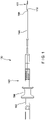
Fig. 1 shows a longitudinal side view of a device according to an exemplary embodiment of the present disclosure; -
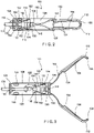
Fig. 2 shows a partially transparent longitudinal side view of a clip according to the device ofFig. 1 ; -
Fig. 3 shows another partially transparent longitudinal side view of the clip ofFig. 2 , in an open configuration; -
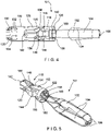
Fig. 4 shows another partially transparent longitudinal side view of the clip ofFig. 2 , rotated 90 degrees about a longitudinal axis thereof and in the open configuration; -
Fig. 5 shows a perspective view of a deployment mechanism, locking mechanism and clip arms of the clip ofFig. 2 ; -
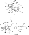
Fig. 6 shows a perspective view of a deployment mechanism and locking mechanism of the clip ofFig. 2 ; and -
Fig. 7 shows a longitudinal side view of a deployment mechanism and clip arms of the clip ofFig. 2 . - The present disclosure may be further understood with reference to the following description and the appended drawings, wherein like elements are referred to with the same reference numerals. The present disclosure is directed to an endoscopic clipping device for treating internal tissue perforations, defects and/or bleeds. In some embodiments, a shorter deployed clip may be preferred to improve visualization of the target site and to allow better maneuverability when placing multiple clips. Exemplary embodiments of the present disclosure describe a clip including clip arms defined via a one-piece element slidable within a capsule to move the clip between an open configuration and a closed configuration to clip target tissue, as desired. The one-piece element is connected to a separate deployment mechanism and locking mechanism to decrease a length of a deployed clip relative to other conventional clip designs which include capsules. It will be understood by those of skill in the art that the terms proximal and distal as used herein, are intended to refer to a direction toward and away from, respectively, a user of the device.
- As shown in
Figs. 1 - 7 , aclip device 100 according to an exemplary embodiment of the present disclosure comprises aclip 101 including a one-piece element 102 defining a pair ofclip arms 104 received within acapsule 106 to move theclip arms 104 between an open configuration, in whichdistal ends 108 of theclip arms 104 are separated from one another, and a closed configuration, in which thedistal ends 108 are drawn toward one another to grip tissue. In embodiments, the one-piece element 102 extends from afirst end 110 to asecond end 112 and is bent, for example, at a joint ormidpoint 114 to define theclip arms 104. Themidpoint 114 is connected to adeployment mechanism 116 including atension member 118 and ayoke 120, which are slidably received within thecapsule 106 to move theclip arms 104 between the open and the closed configuration. - A
locking mechanism 122 is coupled to the one-piece element 102 and thedeployment mechanism 116 so that, when theclip 101 is deployed over target tissue in a body, theclip 101 is locked in the closed configuration. In one embodiment, as shown inFig. 1 , theclip 101 is releasably coupled to an elongatedproximal portion 160 of thedevice 100 sized to facilitate insertion of theclip 101 through a working channel of an endoscope to a target site within the body while a proximal end remains outside the body accessible to a user. Theproximal portion 160 may include, for example, ahandle member 162 includingactuators 164 enabling a user to control movement and deployment of theclip 101 and aflexible shaft 166 extending distally from thehandle member 162 to theclip 101, adistal end 168 of theflexible shaft 166 being releasably coupled to theclip 101 via, for example, a bushing 172. The user manipulates theactuators 164 to move acontrol member 170 that extends from thehandle member 162, through theflexible shaft 166 to connect to theclip arms 104 to control movement of theclip arms 104 between the open and closed configurations. - The
capsule 106 extends from aproximal end 124 to adistal end 126 and includes achannel 128 extending therethrough. In one embodiment, theproximal end 124 is configured to be releasably coupled to the proximal portion of the device viatabs 130 at theproximal end 124 of thecapsule 106, which may be crimped radially inward to engage a corresponding portion of the proximal portion. Thecapsule 106 also includes, for example, locking features formed in a capsule wall such as, for example, lockingwindows 132 that extend laterally through the capsule wall for engaging a portion of thelocking mechanism 122, as will be described in further detail below. - In one embodiment, the
capsule 106 may have a length ranging from between 7.5 mm to 8.55 mm. Thecapsule 106 of this embodiment is substantially shorter than capsule lengths of some conventional clips, which may have lengths ranging from between 12.5 mm to 13.5 mm. It will be understood by those of skill in the art that the one-piece design of theclip arms 104 and theseparate locking mechanism 122, which will be described in further detail below, permits thecapsule 106 to have a shorter length relative to some existing clips without sacrificing an opening width of theclip arms 104. - As described above, the
clip arms 104 are formed from a one-piece element 102 which extends along a length from thefirst end 110 to thesecond end 112 and is bent at, for example, themidpoint 114 so that theclip arms 104 extend along a portion of a length extending from opposite sides of themidpoint 114, e.g., proximal of the first and second ends 110, 112. Thus, the first and second ends 110, 112 of the one-piece element 102 correspond to the distal ends 108 of theclip arms 104. Themidpoint 114 is connected to thedeployment mechanism 116 which is slidably received within thechannel 128 of thecapsule 106 so that theclip arms 104 are movable between the open and the closed configurations. - In one embodiment, the
clip arms 104 are biased toward the open configuration so that, when advanced distally out of thecapsule 106, theclip arms 104 move apart from one another into the open configuration under their natural bias. When thearms 104 are drawn proximally into thecapsule 106, theclip arms 104 are constrained by the wall of thecapsule 106 and drawn together into the closed position with the distal ends 108 adjacent one another. Those skilled in the art will understand that any number of other mechanisms for opening and closing theclip arms 104 may be employed. It will also be understood by those of skill in the art that although the exemplary embodiments show and describe a one-piece element 102 including a bend to formclip arms 104, in an alternative embodiment, proximal ends of clip arms may be attached to one another such that the proximal ends are connectable to thetension member 118. - The
clip arms 104 of this embodiment also include engagingfeatures 134 extending therefrom and configured to engage a portion of thecapsule 106 so that, when the engagingfeatures 134 engage thecapsule 106, theclip arms 104 are prevented from being moved further proximally into thecapsule 106. In one embodiment, the engagingfeatures 134 extend laterally outward from portions of theclip arms 104 so that portions of theclip arms 104 distal of the engagingfeatures 134 have a greater width than portions of theclip arms 104 proximal of the engaging features 134. The portions of theclip arms 104 extending proximal of the engagingfeatures 134 are sized to permit these portions of theclip arms 104 to be drawn proximally into thecapsule 106. - As the proximal portions of the
clip arms 104 are drawn proximally into thecapsule 106, the engagingfeatures 134 abut a portion of adistal face 127 of thecapsule 106 preventing theclip arms 104 from being drawn further proximally into thecapsule 106. The engaging features 134 are positioned along the length of theclip arms 104 so that, at the point where the engagingfeatures 134 have engaged thecapsule 106, theclip arms 104 have been drawn sufficiently proximally into thecapsule 106 to draw theclip arms 104 together into the closed configuration. In one example, the engagingfeatures 134 are configured as wings extending laterally from longitudinal edges of theclip arms 104. - The
tension member 118 extends from aproximal end 136 configured to be releasably coupled to theyoke 120 to adistal end 138 attached to themidpoint 114 of the one-piece element 102 via, for example, apin 140. In one embodiment, thedistal end 138 extends over themidpoint 114 such that thepin 140, which extends diametrically across thedistal end 138, is received within a substantially rounded space at aproximal end 158 of theclip arms 104 defined by the bend of the one-piece element 102 at themidpoint 114. In other words, thepin 140 extends immediately distal of themidpoint 114 so that thepin 140 extends between the pair ofarms 104 along an interior surface of the one-piece element 102 along the bend at themidpoint 114. Thetension member 118 and thepin 140 are connected to the one-piece element 102 such that longitudinal movement of thetension member 118 relative to thecapsule 106 correspondingly moves theclip arms 104 relative to thecapsule 106. Theproximal end 136 of thetension member 118 is sized and shaped to engage a correspondingly sized and shaped portion of theyoke 120. In one embodiment, theproximal end 136 includes a substantially C-shaped protrusion. - The
yoke 120 extends from aproximal end 142 configured to be connected to a control member such as, for example, a pull wire to adistal end 144 configured to releasably engage theproximal end 136 of thetension member 118. In one embodiment, thedistal end 144 included a substantially C-shapedrecess 146 sized and shaped to receive the C-shaped protrusion of theproximal end 136. Theproximal end 136 of thetension member 118 and thedistal end 144 of theyoke 120 are configured to disengage one another when subject to a predetermined force as will be described in more detail below. - In one embodiment, a width along at least a portion of the
yoke 120 substantially corresponds to a width (e.g., diameter) of thechannel 128 of thecapsule 106 so that, when theyoke 120 is positioned within theproximal end 124 of thecapsule 106, theyoke 120 engages thetabs 130 to move thetabs 130 radially outward, out of engagement with the proximal portion of the device. Theyoke 120 also includes a pair ofoverhangs 148 extending distally from a portion thereof. As will be described in further detail below, theoverhangs 148 are configured to constrainproximal ends 154 of lockingarms 152 of thelocking mechanism 122 so that the lockingarms 154 are prevented from engaging the locking features 134 of thecapsule 106 until theclip 101 has been deployed over target tissue. - The
locking mechanism 122 is attached to thetension member 118 and, as described above, includes lockingarms 152 that are constrained by theyoke 120 until theclip 101 is deployed. In one embodiment, thelocking mechanism 122 includes aring 150 and a pair of lockingarms 152 extending proximally from thering 150. Thering 150 is attached to thetension member 118 via thesame pin 140 that connects thetension member 118 to theclip arms 104. In particular, thepin 140 extends diametrically across thering 150 so that thering 150 extends about both thedistal end 138 of thetension member 118 and theproximal end 158 of theclip arms 104. - The locking
arms 152 extend proximally from the opposing sides of thering 150 to the proximal ends 154 and, in one embodiment, are biased radially outward. Thering 150 is connected to thetension member 118 so that the lockingarms 152 extend along opposing sides of thetension member 118 to be constrained via theoverhangs 148 of theyoke 120. The proximal ends 154 of the lockingarms 152 include lockingstructures 156 extending therefrom so that, when the proximal ends 154 are permitted to revert to their biased configuration, the lockingstructures 156 engage the locking features 132 of thecapsule 106. In one embodiment, the lockingstructures 156 are configured as locking tabs extending from the proximal ends 154 to engage lockingwindows 132 of thecapsule 106 when the proximal ends 154 are released from theoverhangs 148. As will be described in further detail below, the proximal ends 154 are released and permitted to revert to their radially outwardly biased configuration when the predetermined force is exerted on theyoke 120 to separate theyoke 120 from thetension member 118. - According to an exemplary method, the
clip 101 of theclip device 100 is inserted to a target site within the body via, for example, a working channel of an endoscope. Theclip 101 is inserted through the working channel in the closed configuration so that theclip arms 104 do not damage in interior of the working channel. Once theclip 101 has reached the target site, theclip arms 104 are moved distally relative to thecapsule 106 extending distal portions of theclip arms 104 out of thecapsule 106 and freeing theclip arms 104 to move apart under their natural bias toward the open configuration so that target tissue may be received between theclip arms 104. Theclip 101 may be repeatedly moved between the open and closed configurations until a target portion of tissue is positioned between theclip arms 104 as desired. The user then draws theclip arms 104 proximally intocapsule 106 so that, as theclip arms 104 are drawn into thecapsule 106, theclip arms 104 are drawn toward one another to grip the target tissue between the distal ends 108 of theclip arms 104. As described above, theclip 101 may be moved between the open and closed configurations via movement of, for example, thecontrol member 170 coupled to theyoke 120. - When the user is satisfied that the
clip 101 is in a desired position gripping the target tissue, the user applies increasing proximally directed force to thecontrol member 170 after the engagingfeatures 134 have engaged thecapsule 106, as described above, until the predetermined force is pulling theyoke 120 proximally away from thetension member 118 so that they disengage from one another. As theyoke 120 is separated from thetension member 118, the proximal ends 154 of thelocking mechanism 122 of theclip arms 104 are released from theoverhangs 148 of theyoke 120, freeing the proximal ends 154 to spring toward their radially outwardly biased configuration until the lockingtabs 156 engage the lockingwindows 132 of thecapsule 106, thereby locking theclip 101 in the closed configuration. - The
yoke 120 may then be drawn further proximally relative to the capsule 106 (e.g., via the control member connected thereto) until a portion of theyoke 120 having a width corresponding to thechannel 128 of thecapsule 106 is positioned within theproximal end 124 of thecapsule 106, urging the radially inwardly crimpedtabs 130 radially outward, out of engagement with, for example, thebushing 172 of theproximal portion 160 of thedevice 100 and separating theclip 101 from theproximal portion 160. Thus, theclip 101 remains clipped over the target tissue while theproximal portion 160 may be removed from the body. In one embodiment, upon separation of theclip 101 from theproximal portion 160, thetabs 130 revert to their radially inwardly crimped configuration so that theyoke 120, although separated from thetension member 118, remains attached to theproximal end 124 of thecapsule 106. - In this embodiment, a further proximal force exerted on the
control member 170 separates the control member from theyoke 120, leaving theclip 101 in the body and allowing theproximal portion 160 of thedevice 100, including thecontrol member 170, to be removed therefrom. According to another embodiment, upon separation of thecapsule 106 from theproximal portion 160, theyoke 120 may be drawn proximally out of thecapsule 106 so that theclip 101 remains within the body, clipped over the target tissue, while theproximal portion 160 and theyoke 120 may be removed from the body. - It will be apparent to those skilled in the art that various modifications may be made in the present disclosure, without departing from the scope of the disclosure.
- Preferred embodiments of the present invention are disclosed in the following aspects:
- 1. A device for treating tissue, comprising:
- a capsule extending longitudinally from a proximal end to a distal end and including a channel extending therethrough;
- first and second clip arms, proximal ends of which are received within the channel so that the first and second clip arms are movable relative to one another between an open configuration and a closed configuration;
- a deployment mechanism including a tension member connected to a proximal end of the first and second clip arms, a yoke releasably coupled to the tension member and longitudinally movable relative to the capsule to move the first and second clip arms between the open and closed configurations, the tension member and yoke configured to separate from one another to release the device from a proximal portion thereof, in response to a predetermined proximal force relative to the tension member; and
- a locking mechanism coupled to the deployment mechanism and including a pair of locking fingers configured to engage a corresponding locking feature of the capsule to lock the first and second clip arms in the closed configuration, when the yoke is separated from the tension member.
- 2. The device of aspect 1, wherein the first and second clip arms are defined via a one-piece clipping element extending from a first end to a second end and including a bend along a portion thereof, the bend extending along a midpoint of the one-piece clipping element so that a length of the first and second clip arms substantially correspond.
- 3. The device of aspect 2, wherein a distal end of tension member is connected to the proximal end of the clip arms via a pin extending diametrically across the distal end of the tension member and through a substantially rounded space formed at the proximal end of the clip arms via the bend along the one-piece clipping element.
- 4. The device of aspect 3, wherein the locking mechanism includes a ring coupled to the distal end of the tension member via the pin, the pair of locking fingers extending proximally from the ring.
- 5. The device of any one of aspects 1 to 4, wherein the locking fingers are biased radially outward and include locking structures extending from proximal ends thereof.
- 6. The device of aspect 5, wherein the yoke includes a pair of overhangs constraining the proximal ends of the locking fingers against the yoke and preventing the locking structures from engaging the locking features of the capsule until the yoke is separated from the tension member.
- 7. The device of any one of aspects 1 to 6, wherein the capsule has a length ranging from between approximately 7.5 mm to 8.5 mm.
- 8. The device of any one of aspects 1 to 7, wherein the first and second clip arms are biased toward the open configuration so that, when the first and second clip arms are drawn proximally into the capsule, the first and second clip arms are constrained toward the closed configuration, and when the first and second clip arms are moved distally out of the capsule, the first and second clip arms are permitted to revert to their biased open configuration.
- 9. A clipping device, comprising:
- a clip including a capsule extending longitudinally from a proximal end to a distal end and including a channel extending therethrough, proximal ends of first and second clip arms slidably received within the channel of the capsule to move the first and second clip arms relative to one another between an open configuration and a closed configuration;
- a deployment mechanism including a tension member connected to a proximal end of the first and second clip arms, a yoke releasably coupled to the tension member and couplable to a control member, which is movable relative to the capsule to move the first and second clip arms between the open and closed configurations, the tension member and yoke configured to separate in response to a predetermined proximal force relative to the tension member;
- a locking mechanism coupled to the deployment mechanism and including a pair of locking fingers configured to engage a corresponding locking feature of the capsule to lock the first and second clip arms in the closed configuration, when the yoke is separated from the tension member; and
- a proximal portion releasably coupled to the proximal end of the capsule so that, upon separation of the yoke from the tension member, the clip is released from the proximal portion and deployed in a body over the target tissue.
- 10. The device of aspect 9, wherein the first and second clip arms are defined via a one-piece clipping element extending from a first end to a second end and including a bend along a portion thereof, the bend extending along a midpoint of the one-piece clipping element so that a length of the first and second clip arms substantially correspond.
- 11. The device of aspect 10, wherein a distal end of tension member is connected to the proximal end of the clip arms via a pin extending diametrically across the distal end of the tension member and through a substantially rounded space formed at the proximal end of the clip arms via the bend along the one-piece clipping element.
- 12. The device of aspect 11, wherein the locking mechanism includes a ring coupled to the distal end of the tension member via the pin, the pair of locking fingers extending proximally from the ring.
- 13. The device of any one of aspects 9 to 11, wherein the locking fingers are biased radially outward and include locking structures extending from proximal ends thereof.
- 14. The device of aspect 13, wherein the yoke includes a pair of overhangs constraining the proximal ends of the locking fingers against the yoke and preventing the locking structures from engaging the locking features of the capsule until the yoke is separated from the tension member.
- 15. The device of any one of aspects 9 to 14, wherein the capsule has a length ranging from between approximately 7.5 mm to 8.5 mm.
Claims (14)
- A device for treating tissue, comprising:a capsule extending longitudinally from a proximal end to a distal end and including a channel extending therethrough;a one-piece clipping element defining a pair of clip arms, proximal ends of which are received within the channel so that the first and second clip arms are movable relative to one another between an open configuration and a closed configuration;a deployment mechanism including a tension member connected to a proximal end of the first and second clip arms, a yoke releasably coupled to the tension member and longitudinally movable relative to the capsule to move the first and second clip arms between the open and closed configurations, the tension member and yoke configured to separate from one another to release the device from a proximal portion thereof, in response to a predetermined proximal force relative to the tension member;a locking mechanism coupled to the one-piece clipping element and to the deployment mechanism and including a pair of locking fingers configured to engage a corresponding locking feature of the capsule to lock the first and second clip arms in the closed configuration, when the yoke is separated from the tension member.
- The device of claim 1, wherein the locking mechanism is separate from the one-piece clipping element.
- The device of claim 1 or 2, wherein the one-piece clipping element is separate from the deployment mechanism and the locking mechanism, wherein the one-piece clipping element is connected to the separate deployment mechanism and locking mechanism.
- The device of any one of claims 1 to 3, further including a pin, wherein a distal end of the tension member is connected to the proximal end of the clip arms via the pin.
- The device of claim 4, wherein the pin extends diametrically across the distal end of the tension member.
- The device of claim 4 or 5, wherein the pin extends through a substantially rounded space formed at the proximal end of the clip arms.
- The device of claim 6, wherein the one-piece clipping element extends from a first end to a second end and includes a bend along a portion thereof, the bend extending along a midpoint of the one-piece clipping element so that a length of the first and second clip arms substantially correspond.
- The device of claim 7, wherein the substantially rounded space is formed at the proximal end of the clip arms via the bend along the one-piece clipping element.
- The device of any one of claims 4 to 8, wherein the locking mechanism includes a ring coupled to the distal end of the tension member via the pin, the pair of locking fingers extending proximally from the ring.
- The device of any one of claims 1 to 9, wherein the locking fingers are biased radially outward and include locking structures extending from proximal ends thereof.
- The device of claim 10, wherein the yoke includes a pair of overhangs constraining the proximal ends of the locking fingers against the yoke and preventing the locking structures from engaging the locking features of the capsule until the yoke is separated from the tension member.
- The device of any one of claims 1 to 11, wherein the capsule has a length ranging from between approximately 7.5 mm to 8.5 mm.
- The device of any one of claims 1 to 12, wherein the first and second clip arms are biased toward the open configuration so that, when the first and second clip arms are drawn proximally into the capsule, the first and second clip arms are constrained toward the closed configuration, and when the first and second clip arms are moved distally out of the capsule, the first and second clip arms are permitted to revert to their biased open configuration.
- The device of any one of claims 1 to 13, further comprising a proximal portion releasably coupled to the proximal end of the capsule so that, upon separation of the yoke from the tension member, the clip is released from the proximal portion and deployed in a body over the target tissue.
Applications Claiming Priority (3)
| Application Number | Priority Date | Filing Date | Title |
|---|---|---|---|
| US201962863016P | 2019-06-18 | 2019-06-18 | |
| EP20751372.2A EP3905970B1 (en) | 2019-06-18 | 2020-06-10 | Hemostasis clip short system |
| PCT/US2020/037037 WO2020257024A1 (en) | 2019-06-18 | 2020-06-10 | Hemostasis clip short system |
Related Parent Applications (2)
| Application Number | Title | Priority Date | Filing Date |
|---|---|---|---|
| EP20751372.2A Division-Into EP3905970B1 (en) | 2019-06-18 | 2020-06-10 | Hemostasis clip short system |
| EP20751372.2A Division EP3905970B1 (en) | 2019-06-18 | 2020-06-10 | Hemostasis clip short system |
Publications (2)
| Publication Number | Publication Date |
|---|---|
| EP4032485A1 true EP4032485A1 (en) | 2022-07-27 |
| EP4032485B1 EP4032485B1 (en) | 2025-05-07 |
Family
ID=71948708
Family Applications (2)
| Application Number | Title | Priority Date | Filing Date |
|---|---|---|---|
| EP21217039.3A Active EP4032485B1 (en) | 2019-06-18 | 2020-06-10 | Hemostasis clip short system |
| EP20751372.2A Active EP3905970B1 (en) | 2019-06-18 | 2020-06-10 | Hemostasis clip short system |
Family Applications After (1)
| Application Number | Title | Priority Date | Filing Date |
|---|---|---|---|
| EP20751372.2A Active EP3905970B1 (en) | 2019-06-18 | 2020-06-10 | Hemostasis clip short system |
Country Status (8)
| Country | Link |
|---|---|
| US (3) | US11484314B2 (en) |
| EP (2) | EP4032485B1 (en) |
| JP (3) | JP7368487B2 (en) |
| KR (3) | KR102814683B1 (en) |
| CN (2) | CN113924051B (en) |
| AU (1) | AU2020295355B2 (en) |
| CA (1) | CA3129467C (en) |
| WO (1) | WO2020257024A1 (en) |
Families Citing this family (4)
| Publication number | Priority date | Publication date | Assignee | Title |
|---|---|---|---|---|
| WO2020257024A1 (en) * | 2019-06-18 | 2020-12-24 | Boston Scientific Scimed, Inc. | Hemostasis clip short system |
| WO2023154213A1 (en) * | 2022-02-09 | 2023-08-17 | Boston Scientific Scimed, Inc. | Locking feature for hemostasis clip |
| WO2022257542A1 (en) * | 2022-03-21 | 2022-12-15 | 宁波新跃医疗科技股份有限公司 | Insertable tissue clamping apparatus and movement rod thereof |
| US20240108356A1 (en) * | 2022-09-27 | 2024-04-04 | Boston Scientific Scimed, Inc. | Locking feature for hemostasis clip |
Citations (5)
| Publication number | Priority date | Publication date | Assignee | Title |
|---|---|---|---|---|
| US20050080440A1 (en) * | 2003-09-30 | 2005-04-14 | Durgin Russell F. | Through the scope tension member release clip |
| WO2009155286A1 (en) * | 2008-06-19 | 2009-12-23 | Boston Scientific Scimed, Inc. | Hemostatic clipping devices and methods |
| US20110245855A1 (en) * | 2010-03-30 | 2011-10-06 | Fujifilm Corporation | Ligating apparatus |
| EP2455009A2 (en) * | 2002-08-21 | 2012-05-23 | Olympus Corporation | Ligating device for biological tissue |
| US20130072945A1 (en) * | 2011-09-15 | 2013-03-21 | Fujifilm Corporation | Clip unit and ligation device using the same |
Family Cites Families (18)
| Publication number | Priority date | Publication date | Assignee | Title |
|---|---|---|---|---|
| DE4319829C1 (en) * | 1993-06-16 | 1994-08-25 | Lerch Karl Dieter | Set for treating vascular deformities |
| JP4472217B2 (en) * | 2000-10-16 | 2010-06-02 | オリンパス株式会社 | Biological tissue clip device |
| US6991634B2 (en) * | 2001-05-23 | 2006-01-31 | Pentax Corporation | Clip device of endoscope |
| US7094245B2 (en) | 2001-10-05 | 2006-08-22 | Scimed Life Systems, Inc. | Device and method for through the scope endoscopic hemostatic clipping |
| US7357805B2 (en) | 2001-12-13 | 2008-04-15 | Sumitomo Bakelite Company | Clip device for endoscope and clip for endoscope for use therein |
| JP4242614B2 (en) | 2002-08-21 | 2009-03-25 | オリンパス株式会社 | Biological tissue ligation device |
| US7727247B2 (en) * | 2002-08-21 | 2010-06-01 | Olympus Corporation | Living tissue ligation device |
| US7494461B2 (en) | 2003-09-30 | 2009-02-24 | Boston Scientific Scimed, Inc. | Through the scope tension member release clip |
| JP4758173B2 (en) * | 2004-12-24 | 2011-08-24 | オリンパス株式会社 | Ligation device |
| US8152822B2 (en) | 2006-12-05 | 2012-04-10 | Cook Medical Technologies Llc | Combination therapy hemostatic clip |
| JP5006753B2 (en) * | 2007-10-17 | 2012-08-22 | Hoya株式会社 | Endoscopic clip device |
| JP2013027458A (en) | 2011-07-27 | 2013-02-07 | Sony Corp | Information processing apparatus, information processing method, and program |
| US9138234B2 (en) | 2011-11-14 | 2015-09-22 | Anrei Medical (Hz) Co., Ltd. | Clip apparatus for ligature of living tissue |
| EP2897534A1 (en) * | 2012-09-24 | 2015-07-29 | Boston Scientific Scimed, Inc. | Release mechanism for hemostatic clip |
| EP3970636B1 (en) * | 2016-08-22 | 2025-10-29 | Boston Scientific Limited | Hemostasis reloadable clipping device with sleeve engagement |
| CN109922743B (en) * | 2016-11-22 | 2021-12-14 | 波士顿科学有限公司 | Hemostatic Reloadable Clip Release Mechanism |
| CA3033084C (en) * | 2016-12-06 | 2021-02-23 | Boston Scientific Scimed, Inc. | Compressive coupler for reloadable hemostasis clipping device |
| WO2020257024A1 (en) * | 2019-06-18 | 2020-12-24 | Boston Scientific Scimed, Inc. | Hemostasis clip short system |
-
2020
- 2020-06-10 WO PCT/US2020/037037 patent/WO2020257024A1/en not_active Ceased
- 2020-06-10 US US16/898,130 patent/US11484314B2/en active Active
- 2020-06-10 JP JP2021551836A patent/JP7368487B2/en active Active
- 2020-06-10 CA CA3129467A patent/CA3129467C/en active Active
- 2020-06-10 EP EP21217039.3A patent/EP4032485B1/en active Active
- 2020-06-10 KR KR1020247022622A patent/KR102814683B1/en active Active
- 2020-06-10 KR KR1020257017357A patent/KR20250085837A/en active Pending
- 2020-06-10 KR KR1020217027744A patent/KR102683750B1/en active Active
- 2020-06-10 CN CN202080042308.6A patent/CN113924051B/en active Active
- 2020-06-10 CN CN202510094311.7A patent/CN119655819A/en active Pending
- 2020-06-10 AU AU2020295355A patent/AU2020295355B2/en active Active
- 2020-06-10 EP EP20751372.2A patent/EP3905970B1/en active Active
-
2022
- 2022-09-29 US US17/936,726 patent/US12076015B2/en active Active
-
2023
- 2023-08-04 JP JP2023127658A patent/JP7635313B2/en active Active
-
2024
- 2024-07-31 US US18/790,650 patent/US20240390005A1/en active Pending
-
2025
- 2025-02-12 JP JP2025020420A patent/JP2025072594A/en active Pending
Patent Citations (5)
| Publication number | Priority date | Publication date | Assignee | Title |
|---|---|---|---|---|
| EP2455009A2 (en) * | 2002-08-21 | 2012-05-23 | Olympus Corporation | Ligating device for biological tissue |
| US20050080440A1 (en) * | 2003-09-30 | 2005-04-14 | Durgin Russell F. | Through the scope tension member release clip |
| WO2009155286A1 (en) * | 2008-06-19 | 2009-12-23 | Boston Scientific Scimed, Inc. | Hemostatic clipping devices and methods |
| US20110245855A1 (en) * | 2010-03-30 | 2011-10-06 | Fujifilm Corporation | Ligating apparatus |
| US20130072945A1 (en) * | 2011-09-15 | 2013-03-21 | Fujifilm Corporation | Clip unit and ligation device using the same |
Also Published As
| Publication number | Publication date |
|---|---|
| CN113924051B (en) | 2025-02-11 |
| EP3905970B1 (en) | 2022-12-14 |
| KR20240110115A (en) | 2024-07-12 |
| JP7368487B2 (en) | 2023-10-24 |
| KR102814683B1 (en) | 2025-05-29 |
| CA3129467C (en) | 2025-06-10 |
| CN113924051A (en) | 2022-01-11 |
| US12076015B2 (en) | 2024-09-03 |
| KR20210130731A (en) | 2021-11-01 |
| JP2025072594A (en) | 2025-05-09 |
| AU2020295355B2 (en) | 2022-12-15 |
| CN119655819A (en) | 2025-03-21 |
| US11484314B2 (en) | 2022-11-01 |
| JP2022522496A (en) | 2022-04-19 |
| EP4032485B1 (en) | 2025-05-07 |
| KR20250085837A (en) | 2025-06-12 |
| US20230014853A1 (en) | 2023-01-19 |
| US20200397436A1 (en) | 2020-12-24 |
| WO2020257024A1 (en) | 2020-12-24 |
| CA3129467A1 (en) | 2020-12-24 |
| EP3905970A1 (en) | 2021-11-10 |
| JP7635313B2 (en) | 2025-02-25 |
| JP2023162219A (en) | 2023-11-08 |
| AU2020295355A1 (en) | 2021-08-12 |
| KR102683750B1 (en) | 2024-07-10 |
| US20240390005A1 (en) | 2024-11-28 |
Similar Documents
| Publication | Publication Date | Title |
|---|---|---|
| JP7477548B2 (en) | Hemostatic clip | |
| US12220133B2 (en) | Hemostasis clip deployment | |
| US12076015B2 (en) | Hemostasis clip short system | |
| KR102810437B1 (en) | A clipping device with a deployment mechanism that shortens the length of the deployed clip | |
| EP3897406B1 (en) | Hemostasis clip with collapsible capsule |
Legal Events
| Date | Code | Title | Description |
|---|---|---|---|
| PUAI | Public reference made under article 153(3) epc to a published international application that has entered the european phase |
Free format text: ORIGINAL CODE: 0009012 |
|
| STAA | Information on the status of an ep patent application or granted ep patent |
Free format text: STATUS: REQUEST FOR EXAMINATION WAS MADE |
|
| 17P | Request for examination filed |
Effective date: 20211222 |
|
| AC | Divisional application: reference to earlier application |
Ref document number: 3905970 Country of ref document: EP Kind code of ref document: P |
|
| AK | Designated contracting states |
Kind code of ref document: A1 Designated state(s): AL AT BE BG CH CY CZ DE DK EE ES FI FR GB GR HR HU IE IS IT LI LT LU LV MC MK MT NL NO PL PT RO RS SE SI SK SM TR |
|
| GRAP | Despatch of communication of intention to grant a patent |
Free format text: ORIGINAL CODE: EPIDOSNIGR1 |
|
| STAA | Information on the status of an ep patent application or granted ep patent |
Free format text: STATUS: GRANT OF PATENT IS INTENDED |
|
| INTG | Intention to grant announced |
Effective date: 20241220 |
|
| GRAS | Grant fee paid |
Free format text: ORIGINAL CODE: EPIDOSNIGR3 |
|
| GRAA | (expected) grant |
Free format text: ORIGINAL CODE: 0009210 |
|
| STAA | Information on the status of an ep patent application or granted ep patent |
Free format text: STATUS: THE PATENT HAS BEEN GRANTED |
|
| AC | Divisional application: reference to earlier application |
Ref document number: 3905970 Country of ref document: EP Kind code of ref document: P |
|
| AK | Designated contracting states |
Kind code of ref document: B1 Designated state(s): AL AT BE BG CH CY CZ DE DK EE ES FI FR GB GR HR HU IE IS IT LI LT LU LV MC MK MT NL NO PL PT RO RS SE SI SK SM TR |
|
| RAP3 | Party data changed (applicant data changed or rights of an application transferred) |
Owner name: BOSTON SCIENTIFIC SCIMED, INC. |
|
| REG | Reference to a national code |
Ref country code: GB Ref legal event code: FG4D |
|
| REG | Reference to a national code |
Ref country code: CH Ref legal event code: EP |
|
| REG | Reference to a national code |
Ref country code: DE Ref legal event code: R096 Ref document number: 602020051128 Country of ref document: DE |
|
| REG | Reference to a national code |
Ref country code: IE Ref legal event code: FG4D |
|
| PGFP | Annual fee paid to national office [announced via postgrant information from national office to epo] |
Ref country code: DE Payment date: 20250520 Year of fee payment: 6 |
|
| PGFP | Annual fee paid to national office [announced via postgrant information from national office to epo] |
Ref country code: GB Payment date: 20250619 Year of fee payment: 6 |
|
| PGFP | Annual fee paid to national office [announced via postgrant information from national office to epo] |
Ref country code: NL Payment date: 20250606 Year of fee payment: 6 |
|
| REG | Reference to a national code |
Ref country code: NL Ref legal event code: FP |
|
| PGFP | Annual fee paid to national office [announced via postgrant information from national office to epo] |
Ref country code: IE Payment date: 20250623 Year of fee payment: 6 |
|
| PG25 | Lapsed in a contracting state [announced via postgrant information from national office to epo] |
Ref country code: ES Free format text: LAPSE BECAUSE OF FAILURE TO SUBMIT A TRANSLATION OF THE DESCRIPTION OR TO PAY THE FEE WITHIN THE PRESCRIBED TIME-LIMIT Effective date: 20250507 Ref country code: PT Free format text: LAPSE BECAUSE OF FAILURE TO SUBMIT A TRANSLATION OF THE DESCRIPTION OR TO PAY THE FEE WITHIN THE PRESCRIBED TIME-LIMIT Effective date: 20250908 Ref country code: FI Free format text: LAPSE BECAUSE OF FAILURE TO SUBMIT A TRANSLATION OF THE DESCRIPTION OR TO PAY THE FEE WITHIN THE PRESCRIBED TIME-LIMIT Effective date: 20250507 |
|
| REG | Reference to a national code |
Ref country code: LT Ref legal event code: MG9D |
|
| PG25 | Lapsed in a contracting state [announced via postgrant information from national office to epo] |
Ref country code: NO Free format text: LAPSE BECAUSE OF FAILURE TO SUBMIT A TRANSLATION OF THE DESCRIPTION OR TO PAY THE FEE WITHIN THE PRESCRIBED TIME-LIMIT Effective date: 20250807 Ref country code: GR Free format text: LAPSE BECAUSE OF FAILURE TO SUBMIT A TRANSLATION OF THE DESCRIPTION OR TO PAY THE FEE WITHIN THE PRESCRIBED TIME-LIMIT Effective date: 20250808 |
|
| PG25 | Lapsed in a contracting state [announced via postgrant information from national office to epo] |
Ref country code: PL Free format text: LAPSE BECAUSE OF FAILURE TO SUBMIT A TRANSLATION OF THE DESCRIPTION OR TO PAY THE FEE WITHIN THE PRESCRIBED TIME-LIMIT Effective date: 20250507 |
|
| REG | Reference to a national code |
Ref country code: AT Ref legal event code: MK05 Ref document number: 1791579 Country of ref document: AT Kind code of ref document: T Effective date: 20250507 |
|
| PG25 | Lapsed in a contracting state [announced via postgrant information from national office to epo] |
Ref country code: BG Free format text: LAPSE BECAUSE OF FAILURE TO SUBMIT A TRANSLATION OF THE DESCRIPTION OR TO PAY THE FEE WITHIN THE PRESCRIBED TIME-LIMIT Effective date: 20250507 |
|
| PG25 | Lapsed in a contracting state [announced via postgrant information from national office to epo] |
Ref country code: HR Free format text: LAPSE BECAUSE OF FAILURE TO SUBMIT A TRANSLATION OF THE DESCRIPTION OR TO PAY THE FEE WITHIN THE PRESCRIBED TIME-LIMIT Effective date: 20250507 |
|
| PG25 | Lapsed in a contracting state [announced via postgrant information from national office to epo] |
Ref country code: AT Free format text: LAPSE BECAUSE OF FAILURE TO SUBMIT A TRANSLATION OF THE DESCRIPTION OR TO PAY THE FEE WITHIN THE PRESCRIBED TIME-LIMIT Effective date: 20250507 |
|
| PG25 | Lapsed in a contracting state [announced via postgrant information from national office to epo] |
Ref country code: RS Free format text: LAPSE BECAUSE OF FAILURE TO SUBMIT A TRANSLATION OF THE DESCRIPTION OR TO PAY THE FEE WITHIN THE PRESCRIBED TIME-LIMIT Effective date: 20250807 |
|
| PG25 | Lapsed in a contracting state [announced via postgrant information from national office to epo] |
Ref country code: IS Free format text: LAPSE BECAUSE OF FAILURE TO SUBMIT A TRANSLATION OF THE DESCRIPTION OR TO PAY THE FEE WITHIN THE PRESCRIBED TIME-LIMIT Effective date: 20250907 |
|
| PG25 | Lapsed in a contracting state [announced via postgrant information from national office to epo] |
Ref country code: LV Free format text: LAPSE BECAUSE OF FAILURE TO SUBMIT A TRANSLATION OF THE DESCRIPTION OR TO PAY THE FEE WITHIN THE PRESCRIBED TIME-LIMIT Effective date: 20250507 |
|
| PG25 | Lapsed in a contracting state [announced via postgrant information from national office to epo] |
Ref country code: SM Free format text: LAPSE BECAUSE OF FAILURE TO SUBMIT A TRANSLATION OF THE DESCRIPTION OR TO PAY THE FEE WITHIN THE PRESCRIBED TIME-LIMIT Effective date: 20250507 Ref country code: DK Free format text: LAPSE BECAUSE OF FAILURE TO SUBMIT A TRANSLATION OF THE DESCRIPTION OR TO PAY THE FEE WITHIN THE PRESCRIBED TIME-LIMIT Effective date: 20250507 |
|
| PG25 | Lapsed in a contracting state [announced via postgrant information from national office to epo] |
Ref country code: CZ Free format text: LAPSE BECAUSE OF FAILURE TO SUBMIT A TRANSLATION OF THE DESCRIPTION OR TO PAY THE FEE WITHIN THE PRESCRIBED TIME-LIMIT Effective date: 20250507 |
|
| PG25 | Lapsed in a contracting state [announced via postgrant information from national office to epo] |
Ref country code: EE Free format text: LAPSE BECAUSE OF FAILURE TO SUBMIT A TRANSLATION OF THE DESCRIPTION OR TO PAY THE FEE WITHIN THE PRESCRIBED TIME-LIMIT Effective date: 20250507 |
|
| PG25 | Lapsed in a contracting state [announced via postgrant information from national office to epo] |
Ref country code: SK Free format text: LAPSE BECAUSE OF FAILURE TO SUBMIT A TRANSLATION OF THE DESCRIPTION OR TO PAY THE FEE WITHIN THE PRESCRIBED TIME-LIMIT Effective date: 20250507 |
|
| REG | Reference to a national code |
Ref country code: CH Ref legal event code: H13 Free format text: ST27 STATUS EVENT CODE: U-0-0-H10-H13 (AS PROVIDED BY THE NATIONAL OFFICE) Effective date: 20260127 |
|
| PG25 | Lapsed in a contracting state [announced via postgrant information from national office to epo] |
Ref country code: IT Free format text: LAPSE BECAUSE OF FAILURE TO SUBMIT A TRANSLATION OF THE DESCRIPTION OR TO PAY THE FEE WITHIN THE PRESCRIBED TIME-LIMIT Effective date: 20250507 |
|
| PG25 | Lapsed in a contracting state [announced via postgrant information from national office to epo] |
Ref country code: RO Free format text: LAPSE BECAUSE OF FAILURE TO SUBMIT A TRANSLATION OF THE DESCRIPTION OR TO PAY THE FEE WITHIN THE PRESCRIBED TIME-LIMIT Effective date: 20250507 |
|
| REG | Reference to a national code |
Ref country code: DE Ref legal event code: R097 Ref document number: 602020051128 Country of ref document: DE |
|
| PG25 | Lapsed in a contracting state [announced via postgrant information from national office to epo] |
Ref country code: LU Free format text: LAPSE BECAUSE OF NON-PAYMENT OF DUE FEES Effective date: 20250610 |
|
| PG25 | Lapsed in a contracting state [announced via postgrant information from national office to epo] |
Ref country code: MC Free format text: LAPSE BECAUSE OF FAILURE TO SUBMIT A TRANSLATION OF THE DESCRIPTION OR TO PAY THE FEE WITHIN THE PRESCRIBED TIME-LIMIT Effective date: 20250507 |
|
| REG | Reference to a national code |
Ref country code: BE Ref legal event code: MM Effective date: 20250630 |
|
| PLBE | No opposition filed within time limit |
Free format text: ORIGINAL CODE: 0009261 |
|
| STAA | Information on the status of an ep patent application or granted ep patent |
Free format text: STATUS: NO OPPOSITION FILED WITHIN TIME LIMIT |
|
| REG | Reference to a national code |
Ref country code: CH Ref legal event code: L10 Free format text: ST27 STATUS EVENT CODE: U-0-0-L10-L00 (AS PROVIDED BY THE NATIONAL OFFICE) Effective date: 20260318 |
|
| 26N | No opposition filed |
Effective date: 20260210 |
|
| PG25 | Lapsed in a contracting state [announced via postgrant information from national office to epo] |
Ref country code: BE Free format text: LAPSE BECAUSE OF NON-PAYMENT OF DUE FEES Effective date: 20250630 |
|
| PG25 | Lapsed in a contracting state [announced via postgrant information from national office to epo] |
Ref country code: FR Free format text: LAPSE BECAUSE OF NON-PAYMENT OF DUE FEES Effective date: 20250707 |
|
| PG25 | Lapsed in a contracting state [announced via postgrant information from national office to epo] |
Ref country code: CH Free format text: LAPSE BECAUSE OF NON-PAYMENT OF DUE FEES Effective date: 20250630 |