EP4031746B1 - A configurable workover system and method for adapting the system - Google Patents
A configurable workover system and method for adapting the system Download PDFInfo
- Publication number
- EP4031746B1 EP4031746B1 EP20793567.7A EP20793567A EP4031746B1 EP 4031746 B1 EP4031746 B1 EP 4031746B1 EP 20793567 A EP20793567 A EP 20793567A EP 4031746 B1 EP4031746 B1 EP 4031746B1
- Authority
- EP
- European Patent Office
- Prior art keywords
- valve
- workover
- package
- wireline
- open water
- Prior art date
- Legal status (The legal status is an assumption and is not a legal conclusion. Google has not performed a legal analysis and makes no representation as to the accuracy of the status listed.)
- Active
Links
Images



Classifications
-
- E—FIXED CONSTRUCTIONS
- E21—EARTH OR ROCK DRILLING; MINING
- E21B—EARTH OR ROCK DRILLING; OBTAINING OIL, GAS, WATER, SOLUBLE OR MELTABLE MATERIALS OR A SLURRY OF MINERALS FROM WELLS
- E21B33/00—Sealing or packing boreholes or wells
- E21B33/02—Surface sealing or packing
- E21B33/03—Well heads; Setting-up thereof
- E21B33/068—Well heads; Setting-up thereof having provision for introducing objects or fluids into, or removing objects from, wells
- E21B33/076—Well heads; Setting-up thereof having provision for introducing objects or fluids into, or removing objects from, wells specially adapted for underwater installations
-
- E—FIXED CONSTRUCTIONS
- E21—EARTH OR ROCK DRILLING; MINING
- E21B—EARTH OR ROCK DRILLING; OBTAINING OIL, GAS, WATER, SOLUBLE OR MELTABLE MATERIALS OR A SLURRY OF MINERALS FROM WELLS
- E21B33/00—Sealing or packing boreholes or wells
- E21B33/02—Surface sealing or packing
- E21B33/03—Well heads; Setting-up thereof
- E21B33/035—Well heads; Setting-up thereof specially adapted for underwater installations
Definitions
- the invention relates to a method for adapting a riserless workover system configuration to an open water riser workover system configuration.
- the invention also relates to an open water riser workover system that is configured from a riserless workover system.
- the open water riser workover system comprising a set of equipment which is attached to a subsea Christmas tree and allows safe intervention operations in a hydrocarbon containing well (not shown).
- the open water riser workover system comprises a riser (pressure containing conduit) that extends between the part of the workover arrangement arranged subsea in connection with the well and a drilling rig or vessel arranged at the sea surface.
- a requirement for using an open water riser workover system is that it must be able to disconnect quickly in case of emergency situations, for instance due to rig/vessel drift off.
- the open water riser workover system must thus have a retainer valve arranged in the main bore. The retainer valve is able to retain the fluid in the riser to avoid spillage to the environment when disconnected. It is also a requirement in open water riser work out systems to have a bleed off valve in the system to bleed off pressure to avoid hydraulic lock.
- a riserless system comprises a different configuration than the open riser workover system. This system does not have a riser extending between the workover system arranged subsea and the drilling rig or vessel. The system is less exposed to emergency situations as there is no riser attached between the subsea arrangement and the drilling rig or vessel.
- the riserless system has a wireline shear seal valve assembly arranged in connection with the main bore which facilitates cutting of wireline/coil tubing and sealing of the main bore when the main safety barriers are blocked by the bottom hole assembly tool string.
- Publication AU2009276614B2 discloses a subsea well intervention system.
- the system includes a lower riser package (LRP) and an emergency disconnect package (EDP).
- LRP lower riser package
- EDP emergency disconnect package
- WCP well control package
- WCP well control package
- the lubricator section has a wireline shear seal valve assembly.
- US7114571 B2 discusses a landing string assembly for installing a completion through a marine riser connected to a blowout preventer (BOP).
- BOP blowout preventer
- WO2017097945A1 discloses a safety system for overriding a hydrocarbon control module.
- the system can typically be used in association with subsea workover operations.
- An object of the invention is thus to provide an easy and quick transformation between a workover system that is riserless and a workover system with riser (Open water).
- the method will also be cost effective in that both systems can reuse the same components, like the well control package in both systems in order to configure any of the systems. This also provides a flexible system that is able to easily adapt to any of the systems without having to perform major additional configurations and repositions.
- the invention relates to a method for adapting a riserless workover system configuration into an open water riser workover system configuration, wherein the system comprising an emergency disconnect package arranged between a lubricator section and well control package, the lubricator section comprises a wireline shear seal valve assembly, the system further comprises an emergency disconnect package connector for disconnecting the emergency disconnect package from the well control package in case of emergency.
- the the method comprising the steps of
- the at least one accumulator arrangement is connected to a prearranged hydraulic supply line coupled to the emergency disconnect package connector.
- the wireline shear seal valve assembly comprising a wireline shear seal valve for sealing a main bore of the configured open water riser workover system from above.
- the wireline seal valve assembly comprising a ball valve or a RAM valve.
- the method further comprising the step of arranging a first bleed off valve in connection with the main bore in a position between the wire shear seal valve and the upper production isolation valve (UPIV) 13 in order to bleed off pressure between the wire shear seal valve and the upper production isolation valve (UPIV).
- a first bleed off valve in connection with the main bore in a position between the wire shear seal valve and the upper production isolation valve (UPIV) 13 in order to bleed off pressure between the wire shear seal valve and the upper production isolation valve (UPIV).
- the method further comprising the step of using a second bleed off valve arranged in fluidly connection with the first bleed off valve as a second barrier valve towards the well fluid below the wireline shear seal valve assembly.
- the wireline shear seal valve assembly is turned upside down in the configured open water riser workover system in order to function as a retainer valve in the configured open water riser workover system.
- the method further comprises the step of attaching additional equipment(s) to the configured open workover system.
- the invention further relates to an open water riser workover system having an emergency disconnect package connector for disconnecting the open water riser workover system.
- the system comprising a wire line seal shear valve assembly comprising a wireline shear seal valve adapted to seal a main bore in the open water riser workover system, said system further comprises a first bleed off valve arranged in fluid connection with the main bore, said first bleed off valve being arranged between the wireline shear seal valve and the emergency disconnect package connector in order to bleed off pressure between the emergency disconnect package connector and the wireline seal shear valve.
- the invention further relates to an open water riser workover system comprising a lubricator section and a well control package, the system further comprises an emergency disconnect package arranged between the lubricator section and the well control package.
- Said lubricator section comprising a wireline shear seal valve assembly that is turned upside down, said wireline shear seal valve assembly further comprising a wireline shear seal valve adapted to seal a main bore from above in the configured open workover system.
- the system further comprises at least one accumulator arrangement in connection with the configured open water riser workover system.
- the invention further relates to a riserless workover system comprising an emergency disconnect package positioned between a lower riser package and a lubricator section.
- the lubricator section comprises a wireline shear seal valve assembly adapted to be rotated approximately 180 degrees around a horizontal axis in order to function as a retainer valve, and said emergency disconnect package comprising an emergency disconnect package connector for connection to the lower riser package, said emergency disconnector package connector further comprises at least one connection point for an accumulator arrangement.
- the invention also describes an open water riser workover system having an emergency disconnect package connector for disconnecting the open water riser workover system.
- the system comprising a wire line seal shear valve assembly comprising a wireline shear seal valve adapted to seal a main bore in the open water riser workover system, said system further comprises a first bleed off valve arranged in fluid connection with the main bore, said first bleed off valve being arranged between the wireline shear seal valve and the emergency disconnect package connector in order to bleed off pressure between the emergency disconnect package connector and the wireline seal shear valve.
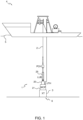
- FIG. 1 and figure 2 shows an overview of the two alternative workover systems.
- the riserless workover system 1 in figure 1 has a wireline 2 that runs through the riserless workover system 1 and a Christmas tree 3 towards a subsea well 6 from a rig/vessel 4 at the sea surface 5.
- the wireline 2 could be attached to various equipment that performs workover operations inside the subsea well 6.
- a lubricator section 25 an emergency disconnector package 20 and a well control package 21.
- the well control package 21 is connected on top of a Christmas tree 3. The principle of the riserless workover system 1 is further described in relation to figure 4 .
- Figure 2 shows another workover principle where there is arranged a pressure containing conduit or riser 31a between a part of the workover system 31b arranged subsea, hereinafter called lower workover riser package 31b, and the drilling rig or vessel 4 at the sea surface 5.
- This is called an open water riser workover system 30'.
- the system comprises a lower riser package 34 and an emergency disconnect package 33 ( figure 3 ).
- the lubricator section 25 is in this system replaced by the riser 31a that extends between the emergency disconnect package 33 and the drilling rig or vessel 4.
- the open water riser workover system will be further described in relation to figure 3 .
- Figure 1 and 2 shows different types of rig/vessel 5. It is to be noted that any type of vessel or rig 5 that is suitable for use in a workover operation are possible embodiments of the invention.
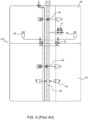
- Figure 3 shows a traditional lower workover riser package 31b for the open water riser workover system 30 illustrated in figure 2 in greater detail.
- the lower workover riser package 31b comprises an emergency disconnect package (EDP) 33 and a lower riser package (LRP) 34, also called a well control package (WCP).
- EDP emergency disconnect package
- LRP lower riser package
- WCP well control package
- a main bore 39 is extending through the system 30 from the riser (31a) to the subsea well 6 for performing workover operations.
- the lower riser package (LRP) 34 is connected to the top of the Christmas tree 3.
- the lower riser package 34 provides a well control function in the open water riser workover system 30.
- the lower riser package 34 of the open water riser workover system further comprises a safety head (SH) 40 and production isolation valve (PIV) 36.
- the emergency disconnect package (EDP) 33 is connected at the top of the lower riser package (LRP) 34.
- the emergency disconnect package 33 comprises an emergency disconnect connector 37 facing the lower riser package (LRP) 34 and connecting the emergency disconnect package (EDP) 33 to the lower riser package (LRP) 34.
- the emergency disconnect package 33 provides the disconnect function in the open water riser workover system.
- the emergency disconnect package (EDP) 33 comprises a retainer valve (RV) 35 attached to the main bore in the system 39.
- the emergency disconnect package 33 In order to perform open water riser workover operations, the emergency disconnect package 33 must be able to disconnect quickly from the lower riser package 34 and retain the fluid in the riser 31 to avoid spillage to the environment and uncontrolled bleed off.
- the emergency disconnect package connector 37 in the emergency disconnect package connects the lower riser package 34 and the emergency disconnect package 33 together.
- the emergency disconnect package connectors 37 are connected to at least one accumulator system 38.
- the accumulator system is known per se.
- the at least one accumulator system 38 will provide hydraulic power to enable emergency quick disconnect within required timeframe and is a requirement in open workover riser systems.
- the retainer valve (RV) 35 In addition, in the emergency disconnection of the open water riser workover r system, the retainer valve (RV) 35 must be closed off to retain the fluid in the riser 31a. Also, the pressure between the retainer valve (RV) 35 and the production isolation valve (PIV) 36 must bleed off to avoid hydraulic lock which prevents disconnection of the emergency disconnect package (EDP) 33.
- Reference number 41 illustrates bleed off valves (BOV1, BOV2) in this system.
- the system When a need for quick emergency disconnection, for instance due to rig/vessel drift off, the system will perform a controlled quick disconnection where the emergency disconnect package 33 will be disconnected from the lower riser package 34 and avoid spillage to the environment and uncontrolled bleed off by closing the retainer valve 35.
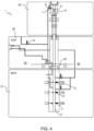
- FIG 4 shows a principle of a riserless workover system 1 in greater detail.
- the system 1 comprises the well control package (WCP) (Lower riser package) 21, the emergency disconnect package 20 and the lubricator section 25.
- the main bore 14 is extending through the riserless workover system 1 as illustrated.
- the system 1 further comprises a valve configuration for performing riserless well intervention.
- the well control package (WCP) 21 comprises a safety head (SH) 11, a lower production isolation valve (LPIV) 12 and an upper production isolation valve (UPIV) 13.
- SH safety head
- LPIV lower production isolation valve
- UPIV upper production isolation valve
- Figure 4 further shows a wireline shear seal valve assembly (WSSV) 10 attached to the main bore 14 in the lubricator section 25 of the riserless workover system 1.
- the wireline shear seal valve assembly (WSSV) 10 having a wireline shear seal valve 8 that is arranged above the main bore valve configuration 11, 12, 13.
- the wireline shear seal valve 8 is arranged in the main bore 14.
- the valve 8 is further arranged in the lubricator section 25 of the riserless workover system 1.
- the wireline shear seal valve 8 is adapted to shear or cut off the wireline and seal off the through bore 14 in emergency situations.
- the wireline shear seal valve 8 is normally a ball valve or a ram valve.
- the valve could however also be a gate valve or other valves suitable for use as a wire line shear seal valve.
- the valve 8 is normally hydraulically controlled but the valve 8 is not limited to such operation.
- the wireline shear seal valve 8 is further normally fully opened during workover operations.
- the figure 4 shows no retainer valve as this valve is not required in riserless workover systems.
- the riserless workover system 1 further comprises an emergency disconnect package connector 22 as part of the emergency disconnect package 20.
- the emergency disconnect package connector 22 is adapted to connect the disconnect package 20 to the well control package (WCP) 21.
- the riserless workover system 1 further comprises an upper circulation valve (UCIRC) 7 used for circulation purposes in riserless operation, that is arranged in a branch 9 from the main bore 14.
- the branch 9 is further arranged above the wireline shear seal valve 8 and in fluid communication with a lower circulation valve (CIRC) 16.
- UCIRC upper circulation valve
- Figure 5 and 6 shows a workover system1', 30' according to the invention.
- the system is designed so that it can be re-configured from a riserless workover system 1' from figure 5 into an open water riser workover configuration 30' in figure 6 .
- the highlighted parts in figure 5 are central elements in this reconfiguration process.
- the figure 5-6 further discloses a wireline shear seal valve assembly 15 is attached to the main bore 14 in the lubricator section 25.
- This shear seal valve assembly differs from the wireline shear seal assembly 10 in figure 4 in that the assembly is configurable as will be described below.
- This shear seal valve assembly 15 has to be released from the riserless workover system 1'.
- This assembly 15 can be turned upside down, i.e. turned approximately 180 degrees around a horizontally arranged axis through the wireline shear valve assembly 15 and re-mounted on the workover arrangement.
- a wireline shear valve 18' arranged within the wireline shear seal valve assembly 15' will then function as a retainer valve that keeps the fluid within the riser when the emergency disconnection of the open water riser workover system 30' is activated, i.e. the emergency disconnect package 33 ( figure 3 ) is disconnected from the lower riser package 34 ( Figure 3 ).
- the wireline shear seal valve assembly (WSSV) 15' upside down, a line or branch 19' from the main bore 14, will be located below the wireline shear seal valve 18'.
- the workover system will have a different configuration and thus a different purpose in the workover system prepared for open water riser workover operations 30' than the configuration prepared for riserless workover operations 1'.
- the riserless valves named Ucirc valve 17' and Circ-BV valve 16' will function in a similar way as the bleed off valves (BOVs) 41 (from figure 3 ) to bleed off pressure between the wireline shear seal valve assembly (WSSV) 15' and the production isolation valve (LPIV) 13' to avoid hydraulic lock during EDP disconnection.
- BOVs bleed off valves
- a primary low pressure (LP) supply 52 and/or a secondary low pressure (LP) supply 53 will each contain prearranged hook up points 51 for future hook-up for at least one accumulator package for the primary and secondary unlock of an emergency disconnect package EDP 26 according to the invention.
- Such accumulator packages are illustrated with reference number 50 in figure 6 .
- the connected accumulator(s) 50 will then provide hydraulic power such that an emergency disconnect of the emergency disconnect package (EDP) 26 is provided within the time requirements.
- EDP emergency disconnect package
- the production isolation valve (LPIV) 12 and the safety head 11 will similar now function as the production isolation valve (PIV) 32 and the safety head (SH) 40 shown in the open water riser workover configuration from figure 3 .
- Figure 6 shows the riserless workover system transformed and configured for the use as an open water riser workover system 30'.
- the wireline seal shear valve assembly 15' has been turned upside down at the upper part of the system 30'.
- the wireline shear seal valve 18' will in this position function as a retainer valve.
- the valve 18' will keep the fluid within the riser during emergency disconnecting where the emergency disconnection package 26' is disconnected from the well control package 21.
- the reference number of the new configuration of the wireline seal valve assembly has been changed to 15' to distinguish from the configuration of the valve assembly 15 in the riserless workover system 30 in figure 5 .
- the configuration that has been prepared from riserless workover system 30 to a configured open workover system has reference number 30'.
- the new orientation of the wireline seal valve assembly 15' will result in that the position of the branch 19 (now referred to as 19') from the main bore 14 is arranged between the wireline shear seal valve 18' and the emergency disconnect package connector 22.
- a first bleed off valve (UCIRC) 17' arranged on this branch 19 will bleed off any pressure between the wireline shear seal valve and emergency disconnect package connector 22 through a second bleed off valve (CIRC-BV) 16'.
- UCIRC bleed off valve
- CIRC-BV second bleed off valve
- the first bleed off valve 17 will bleed off pressure between the wireline shear seal valve 18' and the upper production isolation valve (UPIV) 13 such that rocket effect during disconnection, such as the emergency disconnection, and hydraulic lock during reconnection is avoided.
- the second bleed off valve (CIRC-BV) 16 will further function as a second barrier for the pressure to maintain the double barrier principle during normal operations.
Landscapes
- Life Sciences & Earth Sciences (AREA)
- Engineering & Computer Science (AREA)
- Geology (AREA)
- Mining & Mineral Resources (AREA)
- Physics & Mathematics (AREA)
- Environmental & Geological Engineering (AREA)
- Fluid Mechanics (AREA)
- General Life Sciences & Earth Sciences (AREA)
- Geochemistry & Mineralogy (AREA)
- Earth Drilling (AREA)
- Hardware Redundancy (AREA)
Description
- The invention relates to a method for adapting a riserless workover system configuration to an open water riser workover system configuration. The invention also relates to an open water riser workover system that is configured from a riserless workover system.
- There are two main systems for workover operations;
- an open water riser workover system, and
- a riserless workover system.
- The open water riser workover system comprising a set of equipment which is attached to a subsea Christmas tree and allows safe intervention operations in a hydrocarbon containing well (not shown). The open water riser workover system comprises a riser (pressure containing conduit) that extends between the part of the workover arrangement arranged subsea in connection with the well and a drilling rig or vessel arranged at the sea surface. A requirement for using an open water riser workover system is that it must be able to disconnect quickly in case of emergency situations, for instance due to rig/vessel drift off. The open water riser workover system must thus have a retainer valve arranged in the main bore. The retainer valve is able to retain the fluid in the riser to avoid spillage to the environment when disconnected. It is also a requirement in open water riser work out systems to have a bleed off valve in the system to bleed off pressure to avoid hydraulic lock.
- A riserless system comprises a different configuration than the open riser workover system. This system does not have a riser extending between the workover system arranged subsea and the drilling rig or vessel. The system is less exposed to emergency situations as there is no riser attached between the subsea arrangement and the drilling rig or vessel. The riserless system has a wireline shear seal valve assembly arranged in connection with the main bore which facilitates cutting of wireline/coil tubing and sealing of the main bore when the main safety barriers are blocked by the bottom hole assembly tool string.
- Publication
AU2009276614B2 -
US7114571 B2 discusses a landing string assembly for installing a completion through a marine riser connected to a blowout preventer (BOP). - Moreover, publication
US9038726B2 -
WO2017097945A1 discloses a safety system for overriding a hydrocarbon control module. The system can typically be used in association with subsea workover operations. - For achieving access to the well, the operation of a riserless system is much quicker and more efficient than using a riser in an open water riser workover system. However, there is a requirement in certain wells to use an open water riser workover system.
- There would thus be a huge cost savings to provide a system that has the flexibility for adapting to both the riserless system and the open water riser workover system without replacing completely the components of the one with the other. Adapting from the riserless workover system to an open water riser workover system and vice versa would be a great advantage both for the investment of the systems but also in operation time.
- An object of the invention is thus to provide an easy and quick transformation between a workover system that is riserless and a workover system with riser (Open water).
- The method will also be cost effective in that both systems can reuse the same components, like the well control package in both systems in order to configure any of the systems. This also provides a flexible system that is able to easily adapt to any of the systems without having to perform major additional configurations and repositions.
- The invention relates to a method for adapting a riserless workover system configuration into an open water riser workover system configuration, wherein the system comprising an emergency disconnect package arranged between a lubricator section and well control package, the lubricator section comprises a wireline shear seal valve assembly, the system further comprises an emergency disconnect package connector for disconnecting the emergency disconnect package from the well control package in case of emergency. The the method comprising the steps of
- relocate or reposition the wireline shear seal valve assembly by rotating the valve assembly upside down prior to attaching a riser assembly to the configured open water riser workover system, and
- connecting at least one accumulator arrangement to the configured open water riser workover system.
- Preferably, the at least one accumulator arrangement is connected to a prearranged hydraulic supply line coupled to the emergency disconnect package connector.
- Preferably, the wireline shear seal valve assembly comprising a wireline shear seal valve for sealing a main bore of the configured open water riser workover system from above.
- Preferably, the wireline seal valve assembly comprising a ball valve or a RAM valve.
- Preferably, the method further comprising the step of arranging a first bleed off valve in connection with the main bore in a position between the wire shear seal valve and the upper production isolation valve (UPIV) 13 in order to bleed off pressure between the wire shear seal valve and the upper production isolation valve (UPIV).
- Preferably, the method further comprising the step of using a second bleed off valve arranged in fluidly connection with the first bleed off valve as a second barrier valve towards the well fluid below the wireline shear seal valve assembly.
- Preferably the wireline shear seal valve assembly is turned upside down in the configured open water riser workover system in order to function as a retainer valve in the configured open water riser workover system.
- Preferably, the method further comprises the step of attaching additional equipment(s) to the configured open workover system.
- The invention further relates to an open water riser workover system having an emergency disconnect package connector for disconnecting the open water riser workover system. The system comprising a wire line seal shear valve assembly comprising a wireline shear seal valve adapted to seal a main bore in the open water riser workover system, said system further comprises a first bleed off valve arranged in fluid connection with the main bore, said first bleed off valve being arranged between the wireline shear seal valve and the emergency disconnect package connector in order to bleed off pressure between the emergency disconnect package connector and the wireline seal shear valve.
- The invention further relates to an open water riser workover system comprising a lubricator section and a well control package, the system further comprises an emergency disconnect package arranged between the lubricator section and the well control package. Said lubricator section comprising a wireline shear seal valve assembly that is turned upside down, said wireline shear seal valve assembly further comprising a wireline shear seal valve adapted to seal a main bore from above in the configured open workover system.
- Preferably, the system further comprises at least one accumulator arrangement in connection with the configured open water riser workover system.
- The invention further relates to a riserless workover system comprising an emergency disconnect package positioned between a lower riser package and a lubricator section. The lubricator section comprises a wireline shear seal valve assembly adapted to be rotated approximately 180 degrees around a horizontal axis in order to function as a retainer valve, and said emergency disconnect package comprising an emergency disconnect package connector for connection to the lower riser package, said emergency disconnector package connector further comprises at least one connection point for an accumulator arrangement.
- The invention also describes an open water riser workover system having an emergency disconnect package connector for disconnecting the open water riser workover system. The system comprising a wire line seal shear valve assembly comprising a wireline shear seal valve adapted to seal a main bore in the open water riser workover system, said system further comprises a first bleed off valve arranged in fluid connection with the main bore, said first bleed off valve being arranged between the wireline shear seal valve and the emergency disconnect package connector in order to bleed off pressure between the emergency disconnect package connector and the wireline seal shear valve.
-
-
Figure 1 is an overview of a riserless workover system. -
Figure 2 is an overview of an open water riser workover system. -
Figure 3 shows a prior art configuration of an open water riser workover system in greater detail. -
Figure 4 shows a configuration of a riserless workover system. -
Figure 5 shows a detailed view of the riserless workover system and the valves that is used for adapting to an open water riser workover system and also hydraulic point for adapting to an open water riser workover system. -
Figure 6 shows a detailed view of the open water riser workover system adapted from the riserless workover system into the configured open water riser workover system. -
Figure 1 andfigure 2 shows an overview of the two alternative workover systems. The riserless workover system 1 infigure 1 has awireline 2 that runs through the riserless workover system 1 and a Christmastree 3 towards a subsea well 6 from a rig/vessel 4 at thesea surface 5. Thewireline 2 could be attached to various equipment that performs workover operations inside the subsea well 6. - Among the main component of the riserless workover system 1 shown in the
figure 1 are; alubricator section 25, anemergency disconnector package 20 and awell control package 21. Thewell control package 21 is connected on top of aChristmas tree 3. The principle of the riserless workover system 1 is further described in relation tofigure 4 . -
Figure 2 shows another workover principle where there is arranged a pressure containing conduit orriser 31a between a part of theworkover system 31b arranged subsea, hereinafter called lowerworkover riser package 31b, and the drilling rig orvessel 4 at thesea surface 5. This is called an open water riser workover system 30'. The system comprises alower riser package 34 and an emergency disconnect package 33 (figure 3 ). Thelubricator section 25 is in this system replaced by theriser 31a that extends between theemergency disconnect package 33 and the drilling rig orvessel 4. The open water riser workover system will be further described in relation tofigure 3 . -
Figure 1 and2 shows different types of rig/vessel 5. It is to be noted that any type of vessel orrig 5 that is suitable for use in a workover operation are possible embodiments of the invention. -
Figure 3 shows a traditional lowerworkover riser package 31b for the open waterriser workover system 30 illustrated infigure 2 in greater detail. - The lower
workover riser package 31b comprises an emergency disconnect package (EDP) 33 and a lower riser package (LRP) 34, also called a well control package (WCP). Amain bore 39 is extending through thesystem 30 from the riser (31a) to thesubsea well 6 for performing workover operations. - The lower riser package (LRP) 34 is connected to the top of the
Christmas tree 3. Thelower riser package 34 provides a well control function in the open waterriser workover system 30. Thelower riser package 34 of the open water riser workover system further comprises a safety head (SH) 40 and production isolation valve (PIV) 36. - At the top of the lower riser package (LRP) 34, the emergency disconnect package (EDP) 33 is connected. The
emergency disconnect package 33 comprises anemergency disconnect connector 37 facing the lower riser package (LRP) 34 and connecting the emergency disconnect package (EDP) 33 to the lower riser package (LRP) 34. Theemergency disconnect package 33 provides the disconnect function in the open water riser workover system. The emergency disconnect package (EDP) 33 comprises a retainer valve (RV) 35 attached to the main bore in thesystem 39. - In order to perform open water riser workover operations, the
emergency disconnect package 33 must be able to disconnect quickly from thelower riser package 34 and retain the fluid in the riser 31 to avoid spillage to the environment and uncontrolled bleed off. - The emergency
disconnect package connector 37 in the emergency disconnect package connects thelower riser package 34 and theemergency disconnect package 33 together. In order to perform a quick emergency disconnect between thelower riser package 34 and theemergency disconnect package 33, the emergencydisconnect package connectors 37 are connected to at least oneaccumulator system 38. The accumulator system is known per se. The at least oneaccumulator system 38 will provide hydraulic power to enable emergency quick disconnect within required timeframe and is a requirement in open workover riser systems. - In addition, in the emergency disconnection of the open water riser workover r system, the retainer valve (RV) 35 must be closed off to retain the fluid in the
riser 31a. Also, the pressure between the retainer valve (RV) 35 and the production isolation valve (PIV) 36 must bleed off to avoid hydraulic lock which prevents disconnection of the emergency disconnect package (EDP) 33.Reference number 41 illustrates bleed off valves (BOV1, BOV2) in this system. - When a need for quick emergency disconnection, for instance due to rig/vessel drift off, the system will perform a controlled quick disconnection where the
emergency disconnect package 33 will be disconnected from thelower riser package 34 and avoid spillage to the environment and uncontrolled bleed off by closing theretainer valve 35. -
Figure 4 shows a principle of a riserless workover system 1 in greater detail. The system 1 comprises the well control package (WCP) (Lower riser package) 21, theemergency disconnect package 20 and thelubricator section 25. Themain bore 14 is extending through the riserless workover system 1 as illustrated. The system 1 further comprises a valve configuration for performing riserless well intervention. The well control package (WCP) 21 comprises a safety head (SH) 11, a lower production isolation valve (LPIV) 12 and an upper production isolation valve (UPIV) 13. Thevalves main bore 14 extending through the well control package (WCP) 21 from the well 6 (figure 1 ). -
Figure 4 further shows a wireline shear seal valve assembly (WSSV) 10 attached to themain bore 14 in thelubricator section 25 of the riserless workover system 1. The wireline shear seal valve assembly (WSSV) 10 having a wirelineshear seal valve 8 that is arranged above the mainbore valve configuration shear seal valve 8 is arranged in themain bore 14. Thevalve 8 is further arranged in thelubricator section 25 of the riserless workover system 1. The wirelineshear seal valve 8 is adapted to shear or cut off the wireline and seal off the throughbore 14 in emergency situations. The wirelineshear seal valve 8 is normally a ball valve or a ram valve. The valve could however also be a gate valve or other valves suitable for use as a wire line shear seal valve. Thevalve 8 is normally hydraulically controlled but thevalve 8 is not limited to such operation. The wirelineshear seal valve 8 is further normally fully opened during workover operations. Thefigure 4 shows no retainer valve as this valve is not required in riserless workover systems. - The riserless workover system 1 further comprises an emergency
disconnect package connector 22 as part of theemergency disconnect package 20. The emergencydisconnect package connector 22 is adapted to connect thedisconnect package 20 to the well control package (WCP) 21. - The riserless workover system 1 further comprises an upper circulation valve (UCIRC) 7 used for circulation purposes in riserless operation, that is arranged in a
branch 9 from themain bore 14. Thebranch 9 is further arranged above the wirelineshear seal valve 8 and in fluid communication with a lower circulation valve (CIRC) 16. -
Figure 5 and6 shows a workover system1', 30' according to the invention. The system is designed so that it can be re-configured from a riserless workover system 1' fromfigure 5 into an open water riser workover configuration 30' infigure 6 . The highlighted parts infigure 5 are central elements in this reconfiguration process. - The central elements that are affected in the reposition have been renumbered from
figure 4 , while the remaining features fromfigure 4 have the same reference number. - With a reconfiguration and re-using of the
riserless valves - The
figure 5-6 further discloses a wireline shearseal valve assembly 15 is attached to themain bore 14 in thelubricator section 25. This shear seal valve assembly differs from the wirelineshear seal assembly 10 infigure 4 in that the assembly is configurable as will be described below. This shearseal valve assembly 15 has to be released from the riserless workover system 1'. Thisassembly 15 can be turned upside down, i.e. turned approximately 180 degrees around a horizontally arranged axis through the wirelineshear valve assembly 15 and re-mounted on the workover arrangement. A wireline shear valve 18' arranged within the wireline shear seal valve assembly 15' will then function as a retainer valve that keeps the fluid within the riser when the emergency disconnection of the open water riser workover system 30' is activated, i.e. the emergency disconnect package 33 (figure 3 ) is disconnected from the lower riser package 34 (Figure 3 ). By turning the wireline shear seal valve assembly (WSSV) 15' upside down, a line or branch 19' from themain bore 14, will be located below the wireline shear seal valve 18'. - Due to this reposition, the workover system will have a different configuration and thus a different purpose in the workover system prepared for open water riser workover operations 30' than the configuration prepared for riserless workover operations 1'. The riserless valves named Ucirc valve 17' and Circ-BV valve 16' will function in a similar way as the bleed off valves (BOVs) 41 (from
figure 3 ) to bleed off pressure between the wireline shear seal valve assembly (WSSV) 15' and the production isolation valve (LPIV) 13' to avoid hydraulic lock during EDP disconnection. The arrangement is further shown and described in detail infigure 6 . - A primary low pressure (LP)
supply 52 and/or a secondary low pressure (LP)supply 53 will each contain prearranged hook uppoints 51 for future hook-up for at least one accumulator package for the primary and secondary unlock of an emergencydisconnect package EDP 26 according to the invention. Such accumulator packages are illustrated withreference number 50 infigure 6 . The connected accumulator(s) 50 will then provide hydraulic power such that an emergency disconnect of the emergency disconnect package (EDP) 26 is provided within the time requirements. - In its simplest form it may be a common accumulator for the primary and secondary unlock of the emergency disconnect package (EDP) 26. However, in most cases there are arranged an
accumulator package 50 for each primary and secondary unlock due to safety and redundancy criteria. - The production isolation valve (LPIV) 12 and the
safety head 11 will similar now function as the production isolation valve (PIV) 32 and the safety head (SH) 40 shown in the open water riser workover configuration fromfigure 3 . - In addition, there may be pre-arranged and mounted hook up points for further additional equipment(s) that may be useful for the open workover configuration.
-
Figure 6 shows the riserless workover system transformed and configured for the use as an open water riser workover system 30'. In this figure the wireline seal shear valve assembly 15' has been turned upside down at the upper part of the system 30'. - The wireline shear seal valve 18' will in this position function as a retainer valve. The valve 18' will keep the fluid within the riser during emergency disconnecting where the emergency disconnection package 26' is disconnected from the well control
package 21. - The reference number of the new configuration of the wireline seal valve assembly has been changed to 15' to distinguish from the configuration of the
valve assembly 15 in theriserless workover system 30 infigure 5 . Likewise, the configuration that has been prepared fromriserless workover system 30 to a configured open workover system has reference number 30'. - The new orientation of the wireline seal valve assembly 15' will result in that the position of the branch 19 (now referred to as 19') from the
main bore 14 is arranged between the wireline shear seal valve 18' and the emergencydisconnect package connector 22. A first bleed off valve (UCIRC) 17' arranged on thisbranch 19 will bleed off any pressure between the wireline shear seal valve and emergencydisconnect package connector 22 through a second bleed off valve (CIRC-BV) 16'. These valves are the same as thecirculation valves fig. 4 . In the emergency disconnection situations, the first bleed offvalve 17 will bleed off pressure between the wireline shear seal valve 18' and the upper production isolation valve (UPIV) 13 such that rocket effect during disconnection, such as the emergency disconnection, and hydraulic lock during reconnection is avoided. The second bleed off valve (CIRC-BV) 16 will further function as a second barrier for the pressure to maintain the double barrier principle during normal operations. - As mentioned in relation to
figure 3 , another requirement to be able to perform a quick disconnection between the emergency disconnect package 26' and thewell control package 21 in the open water riser workover configuration, is that there are at least oneaccumulator package 50 attached to theemergency disconnect connector 22 throughsupply lines figure 5 )The configurableriserless workover system 30 infigure 5 thus also requires a at least one connection point 51 (figure 5 ) for attaching at least one accumulator arrangement to the configured system 30'. - The present invention has been described with reference to a preferred embodiment and some drawings for the sake of understanding only and it should be clear to persons skilled in the art that the present invention includes all legitimate modifications within the ambit of what has been described hereinbefore and claimed in the appended claims.
Claims (12)
- Method for adapting a riserless workover system configuration (1') into an open water riser workover system configuration (30'), wherein the system comprising an emergency disconnect package (20) arranged between a lubricator section (28) and well control package (21), the lubricator section (28) comprises a wireline shear seal valve assembly (15), the system further comprises an emergency disconnect package connector (22) for disconnecting the emergency disconnect package (26) from the well control package (21) in case of emergency, characterized in that the method comprising the steps of- relocate the wireline shear seal valve assembly (15') by rotating the valve assembly (15) upside down prior to attaching a riser assembly to the configured open water riser workover system (30'), and- connecting at least one accumulator arrangement (50) to the configured open water riser workover system (30').
- Method according to claim 1, wherein the at least one accumulator arrangement (50) is connected to a prearranged hydraulic supply line (52, 53) coupled to the emergency disconnect package connector (22).
- Method according to claim 1 or 2, wherein the wireline shear seal valve assembly (15') comprising a wireline shear seal valve (18') for sealing a main bore (14) of the configured open water riser workover system (30') from above.
- Method according to any of the claims 1- 3, wherein the wireline seal valve assembly (15, 15') comprising a ball valve or a RAM valve.
- Method according to any of the claims 1-4, wherein the method further comprising the step of arranging a first bleed off valve (17) in connection with the main bore (14) in a position between the wire shear seal valve (18') and the upper production isolation valve (UPIV) 13 in order to bleed off pressure between the wire shear seal valve (18') and the upper production isolation valve (UPIV) 13.
- Method according to any of claims 1-5, wherein the method further comprising the step of using a second bleed off valve (16) arranged in fluidly connection with the first bleed off valve (17) as a second barrier valve.
- Method according to any of the claims 1-6, wherein the wireline shear seal valve assembly (15') is turned upside down in the configured open water workover system (30') in order to function as a retainer valve in the configured open water workover system (30').
- Method according to any one of the claims 1-7, wherein the method further comprises the step of attaching additional equipment(s) to the configured open workover system (30').
- A configured open water riser workover system (30') comprising a lubricator section (28') and a well control package (21), the system further comprises an emergency disconnect package (26') arranged between the lubricator section (28') and the well control package (21), characterized in that said lubricator section (28') comprising a wireline shear seal valve assembly (15') that is turned upside down, said wireline shear seal valve assembly (15') further comprising a wireline shear seal valve (18') adapted to seal a main bore (14) from above in the configured open workover system (30').
- The configured open water riser workover system according to claim 9, wherein the system further comprises at least one accumulator arrangement (50) in connection with the configured open water riser workover system (30').
- The configured open water riser workover system according to claim 9 or 10, wherein the system further comprises a first bleed off valve (17) arranged in fluid connection with the main bore (14), said first bleed off valve (17) being arranged between the wireline shear seal valve (18) and the upper production isolation valve (UPIV) 13 in order to bleed off pressure between the upper production isolation valve (UPIV) 13 and the wireline seal shear valve (18').
- A riserless workover system comprising a lubricator section (28), a well control package (21), and an emergency disconnect package (26) positioned between the well control package (21) and the lubricator section (28), characterized in that the lubricator section (28) comprises a wireline shear seal valve assembly (15) adapted to be rotated approximately 180 degrees around a horizontal axis in order to function as a retainer valve, and said emergency disconnect package (26) comprising an emergency disconnect package connector (22) for connection to the well control package (21), said emergency disconnector package connector (22) further comprises at least one connection point (51, 52, 53) for an accumulator arrangement (50).
Applications Claiming Priority (2)
| Application Number | Priority Date | Filing Date | Title |
|---|---|---|---|
| NO20191115A NO346228B1 (en) | 2019-09-16 | 2019-09-16 | A configurable workover system and method for adapting the system |
| PCT/EP2020/075885 WO2021053027A1 (en) | 2019-09-16 | 2020-09-16 | A configurable workover system and method for adapting the system. |
Publications (2)
| Publication Number | Publication Date |
|---|---|
| EP4031746A1 EP4031746A1 (en) | 2022-07-27 |
| EP4031746B1 true EP4031746B1 (en) | 2023-09-13 |
Family
ID=72964621
Family Applications (1)
| Application Number | Title | Priority Date | Filing Date |
|---|---|---|---|
| EP20793567.7A Active EP4031746B1 (en) | 2019-09-16 | 2020-09-16 | A configurable workover system and method for adapting the system |
Country Status (3)
| Country | Link |
|---|---|
| EP (1) | EP4031746B1 (en) |
| NO (1) | NO346228B1 (en) |
| WO (1) | WO2021053027A1 (en) |
Family Cites Families (5)
| Publication number | Priority date | Publication date | Assignee | Title |
|---|---|---|---|---|
| GB2362398B (en) * | 2000-05-16 | 2002-11-13 | Fmc Corp | Device for installation and flow test of subsea completions |
| EP2321491B1 (en) * | 2008-07-31 | 2013-04-10 | BP Corporation North America Inc. | Subsea well intervention systems and methods |
| US9038726B2 (en) * | 2012-06-12 | 2015-05-26 | Vetco Gray U.K., Limited | Light well intervention umbilical and flying lead management system and related methods |
| NO338954B1 (en) * | 2014-06-20 | 2016-11-07 | Capwell As | UNDERWELL BELL INTERVENTION SYSTEM AND PROCEDURE FOR PERFORMING A UNDERWELL BELL INTERVENTION |
| NO342043B1 (en) * | 2015-12-08 | 2018-03-19 | Aker Solutions As | Workover Safety System |
-
2019
- 2019-09-16 NO NO20191115A patent/NO346228B1/en unknown
-
2020
- 2020-09-16 WO PCT/EP2020/075885 patent/WO2021053027A1/en not_active Ceased
- 2020-09-16 EP EP20793567.7A patent/EP4031746B1/en active Active
Also Published As
| Publication number | Publication date |
|---|---|
| EP4031746A1 (en) | 2022-07-27 |
| NO20191115A1 (en) | 2021-03-17 |
| WO2021053027A1 (en) | 2021-03-25 |
| NO346228B1 (en) | 2022-05-02 |
Similar Documents
| Publication | Publication Date | Title |
|---|---|---|
| US9291020B2 (en) | Blowout preventer system with three control pods | |
| US6227300B1 (en) | Slimbore subsea completion system and method | |
| CN102132002B (en) | Subsea well intervention systems and methods | |
| US9458689B2 (en) | System for controlling in-riser functions from out-of-riser control system | |
| US10689934B2 (en) | Chemical deepwater stimulation systems and methods | |
| US20190226297A1 (en) | Modular Blowout Preventer Control System | |
| US7487836B2 (en) | Riserless modular subsea well intervention, method and apparatus | |
| EP3259440B1 (en) | Tool for closed well operation | |
| US9797224B1 (en) | Wellhead stabilizing subsea module | |
| EP2809874B1 (en) | Method and system for rapid containment and intervention of a subsea well blowout | |
| US10081986B2 (en) | Subsea casing tieback | |
| EP2601375B1 (en) | Method and system for performing well operations | |
| US20170067310A1 (en) | Vertical xmas tree and workover assembly | |
| US9874076B2 (en) | Tool arrangement connected to a christmas tree and methods for installing and removing of a christmas tree | |
| EP4031746A1 (en) | A configurable workover system and method for adapting the system |
Legal Events
| Date | Code | Title | Description |
|---|---|---|---|
| STAA | Information on the status of an ep patent application or granted ep patent |
Free format text: STATUS: UNKNOWN |
|
| STAA | Information on the status of an ep patent application or granted ep patent |
Free format text: STATUS: THE INTERNATIONAL PUBLICATION HAS BEEN MADE |
|
| PUAI | Public reference made under article 153(3) epc to a published international application that has entered the european phase |
Free format text: ORIGINAL CODE: 0009012 |
|
| STAA | Information on the status of an ep patent application or granted ep patent |
Free format text: STATUS: REQUEST FOR EXAMINATION WAS MADE |
|
| 17P | Request for examination filed |
Effective date: 20220328 |
|
| AK | Designated contracting states |
Kind code of ref document: A1 Designated state(s): AL AT BE BG CH CY CZ DE DK EE ES FI FR GB GR HR HU IE IS IT LI LT LU LV MC MK MT NL NO PL PT RO RS SE SI SK SM TR |
|
| DAV | Request for validation of the european patent (deleted) | ||
| DAX | Request for extension of the european patent (deleted) | ||
| GRAP | Despatch of communication of intention to grant a patent |
Free format text: ORIGINAL CODE: EPIDOSNIGR1 |
|
| STAA | Information on the status of an ep patent application or granted ep patent |
Free format text: STATUS: GRANT OF PATENT IS INTENDED |
|
| INTG | Intention to grant announced |
Effective date: 20230414 |
|
| GRAS | Grant fee paid |
Free format text: ORIGINAL CODE: EPIDOSNIGR3 |
|
| GRAA | (expected) grant |
Free format text: ORIGINAL CODE: 0009210 |
|
| STAA | Information on the status of an ep patent application or granted ep patent |
Free format text: STATUS: THE PATENT HAS BEEN GRANTED |
|
| AK | Designated contracting states |
Kind code of ref document: B1 Designated state(s): AL AT BE BG CH CY CZ DE DK EE ES FI FR GB GR HR HU IE IS IT LI LT LU LV MC MK MT NL NO PL PT RO RS SE SI SK SM TR |
|
| REG | Reference to a national code |
Ref country code: CH Ref legal event code: EP |
|
| REG | Reference to a national code |
Ref country code: DE Ref legal event code: R096 Ref document number: 602020017727 Country of ref document: DE |
|
| REG | Reference to a national code |
Ref country code: IE Ref legal event code: FG4D |
|
| REG | Reference to a national code |
Ref country code: LT Ref legal event code: MG9D |
|
| REG | Reference to a national code |
Ref country code: NL Ref legal event code: MP Effective date: 20230913 |
|
| PG25 | Lapsed in a contracting state [announced via postgrant information from national office to epo] |
Ref country code: GR Free format text: LAPSE BECAUSE OF FAILURE TO SUBMIT A TRANSLATION OF THE DESCRIPTION OR TO PAY THE FEE WITHIN THE PRESCRIBED TIME-LIMIT Effective date: 20231214 |
|
| PG25 | Lapsed in a contracting state [announced via postgrant information from national office to epo] |
Ref country code: SE Free format text: LAPSE BECAUSE OF FAILURE TO SUBMIT A TRANSLATION OF THE DESCRIPTION OR TO PAY THE FEE WITHIN THE PRESCRIBED TIME-LIMIT Effective date: 20230913 Ref country code: RS Free format text: LAPSE BECAUSE OF FAILURE TO SUBMIT A TRANSLATION OF THE DESCRIPTION OR TO PAY THE FEE WITHIN THE PRESCRIBED TIME-LIMIT Effective date: 20230913 Ref country code: NO Free format text: LAPSE BECAUSE OF FAILURE TO SUBMIT A TRANSLATION OF THE DESCRIPTION OR TO PAY THE FEE WITHIN THE PRESCRIBED TIME-LIMIT Effective date: 20231213 Ref country code: LV Free format text: LAPSE BECAUSE OF FAILURE TO SUBMIT A TRANSLATION OF THE DESCRIPTION OR TO PAY THE FEE WITHIN THE PRESCRIBED TIME-LIMIT Effective date: 20230913 Ref country code: LT Free format text: LAPSE BECAUSE OF FAILURE TO SUBMIT A TRANSLATION OF THE DESCRIPTION OR TO PAY THE FEE WITHIN THE PRESCRIBED TIME-LIMIT Effective date: 20230913 Ref country code: HR Free format text: LAPSE BECAUSE OF FAILURE TO SUBMIT A TRANSLATION OF THE DESCRIPTION OR TO PAY THE FEE WITHIN THE PRESCRIBED TIME-LIMIT Effective date: 20230913 Ref country code: GR Free format text: LAPSE BECAUSE OF FAILURE TO SUBMIT A TRANSLATION OF THE DESCRIPTION OR TO PAY THE FEE WITHIN THE PRESCRIBED TIME-LIMIT Effective date: 20231214 Ref country code: FI Free format text: LAPSE BECAUSE OF FAILURE TO SUBMIT A TRANSLATION OF THE DESCRIPTION OR TO PAY THE FEE WITHIN THE PRESCRIBED TIME-LIMIT Effective date: 20230913 |
|
| REG | Reference to a national code |
Ref country code: AT Ref legal event code: MK05 Ref document number: 1611486 Country of ref document: AT Kind code of ref document: T Effective date: 20230913 |
|
| PG25 | Lapsed in a contracting state [announced via postgrant information from national office to epo] |
Ref country code: NL Free format text: LAPSE BECAUSE OF FAILURE TO SUBMIT A TRANSLATION OF THE DESCRIPTION OR TO PAY THE FEE WITHIN THE PRESCRIBED TIME-LIMIT Effective date: 20230913 |
|
| REG | Reference to a national code |
Ref country code: DE Ref legal event code: R119 Ref document number: 602020017727 Country of ref document: DE |
|
| PG25 | Lapsed in a contracting state [announced via postgrant information from national office to epo] |
Ref country code: IS Free format text: LAPSE BECAUSE OF FAILURE TO SUBMIT A TRANSLATION OF THE DESCRIPTION OR TO PAY THE FEE WITHIN THE PRESCRIBED TIME-LIMIT Effective date: 20240113 |
|
| PG25 | Lapsed in a contracting state [announced via postgrant information from national office to epo] |
Ref country code: AT Free format text: LAPSE BECAUSE OF FAILURE TO SUBMIT A TRANSLATION OF THE DESCRIPTION OR TO PAY THE FEE WITHIN THE PRESCRIBED TIME-LIMIT Effective date: 20230913 |
|
| PG25 | Lapsed in a contracting state [announced via postgrant information from national office to epo] |
Ref country code: ES Free format text: LAPSE BECAUSE OF FAILURE TO SUBMIT A TRANSLATION OF THE DESCRIPTION OR TO PAY THE FEE WITHIN THE PRESCRIBED TIME-LIMIT Effective date: 20230913 |
|
| PG25 | Lapsed in a contracting state [announced via postgrant information from national office to epo] |
Ref country code: SM Free format text: LAPSE BECAUSE OF FAILURE TO SUBMIT A TRANSLATION OF THE DESCRIPTION OR TO PAY THE FEE WITHIN THE PRESCRIBED TIME-LIMIT Effective date: 20230913 Ref country code: RO Free format text: LAPSE BECAUSE OF FAILURE TO SUBMIT A TRANSLATION OF THE DESCRIPTION OR TO PAY THE FEE WITHIN THE PRESCRIBED TIME-LIMIT Effective date: 20230913 Ref country code: IS Free format text: LAPSE BECAUSE OF FAILURE TO SUBMIT A TRANSLATION OF THE DESCRIPTION OR TO PAY THE FEE WITHIN THE PRESCRIBED TIME-LIMIT Effective date: 20240113 Ref country code: ES Free format text: LAPSE BECAUSE OF FAILURE TO SUBMIT A TRANSLATION OF THE DESCRIPTION OR TO PAY THE FEE WITHIN THE PRESCRIBED TIME-LIMIT Effective date: 20230913 Ref country code: EE Free format text: LAPSE BECAUSE OF FAILURE TO SUBMIT A TRANSLATION OF THE DESCRIPTION OR TO PAY THE FEE WITHIN THE PRESCRIBED TIME-LIMIT Effective date: 20230913 Ref country code: CZ Free format text: LAPSE BECAUSE OF FAILURE TO SUBMIT A TRANSLATION OF THE DESCRIPTION OR TO PAY THE FEE WITHIN THE PRESCRIBED TIME-LIMIT Effective date: 20230913 Ref country code: AT Free format text: LAPSE BECAUSE OF FAILURE TO SUBMIT A TRANSLATION OF THE DESCRIPTION OR TO PAY THE FEE WITHIN THE PRESCRIBED TIME-LIMIT Effective date: 20230913 Ref country code: PT Free format text: LAPSE BECAUSE OF FAILURE TO SUBMIT A TRANSLATION OF THE DESCRIPTION OR TO PAY THE FEE WITHIN THE PRESCRIBED TIME-LIMIT Effective date: 20240115 Ref country code: SK Free format text: LAPSE BECAUSE OF FAILURE TO SUBMIT A TRANSLATION OF THE DESCRIPTION OR TO PAY THE FEE WITHIN THE PRESCRIBED TIME-LIMIT Effective date: 20230913 |
|
| REG | Reference to a national code |
Ref country code: CH Ref legal event code: PL |
|
| PG25 | Lapsed in a contracting state [announced via postgrant information from national office to epo] |
Ref country code: LU Free format text: LAPSE BECAUSE OF NON-PAYMENT OF DUE FEES Effective date: 20230916 |
|
| REG | Reference to a national code |
Ref country code: BE Ref legal event code: MM Effective date: 20230930 |
|
| PG25 | Lapsed in a contracting state [announced via postgrant information from national office to epo] |
Ref country code: PL Free format text: LAPSE BECAUSE OF FAILURE TO SUBMIT A TRANSLATION OF THE DESCRIPTION OR TO PAY THE FEE WITHIN THE PRESCRIBED TIME-LIMIT Effective date: 20230913 Ref country code: LU Free format text: LAPSE BECAUSE OF NON-PAYMENT OF DUE FEES Effective date: 20230916 Ref country code: IT Free format text: LAPSE BECAUSE OF FAILURE TO SUBMIT A TRANSLATION OF THE DESCRIPTION OR TO PAY THE FEE WITHIN THE PRESCRIBED TIME-LIMIT Effective date: 20230913 |
|
| PG25 | Lapsed in a contracting state [announced via postgrant information from national office to epo] |
Ref country code: MC Free format text: LAPSE BECAUSE OF FAILURE TO SUBMIT A TRANSLATION OF THE DESCRIPTION OR TO PAY THE FEE WITHIN THE PRESCRIBED TIME-LIMIT Effective date: 20230913 |
|
| REG | Reference to a national code |
Ref country code: IE Ref legal event code: MM4A |
|
| PG25 | Lapsed in a contracting state [announced via postgrant information from national office to epo] |
Ref country code: IE Free format text: LAPSE BECAUSE OF NON-PAYMENT OF DUE FEES Effective date: 20230916 |
|
| PG25 | Lapsed in a contracting state [announced via postgrant information from national office to epo] |
Ref country code: DK Free format text: LAPSE BECAUSE OF FAILURE TO SUBMIT A TRANSLATION OF THE DESCRIPTION OR TO PAY THE FEE WITHIN THE PRESCRIBED TIME-LIMIT Effective date: 20230913 |
|
| PG25 | Lapsed in a contracting state [announced via postgrant information from national office to epo] |
Ref country code: CH Free format text: LAPSE BECAUSE OF NON-PAYMENT OF DUE FEES Effective date: 20230930 |
|
| PLBE | No opposition filed within time limit |
Free format text: ORIGINAL CODE: 0009261 |
|
| STAA | Information on the status of an ep patent application or granted ep patent |
Free format text: STATUS: NO OPPOSITION FILED WITHIN TIME LIMIT |
|
| PG25 | Lapsed in a contracting state [announced via postgrant information from national office to epo] |
Ref country code: MC Free format text: LAPSE BECAUSE OF FAILURE TO SUBMIT A TRANSLATION OF THE DESCRIPTION OR TO PAY THE FEE WITHIN THE PRESCRIBED TIME-LIMIT Effective date: 20230913 Ref country code: IE Free format text: LAPSE BECAUSE OF NON-PAYMENT OF DUE FEES Effective date: 20230916 Ref country code: DK Free format text: LAPSE BECAUSE OF FAILURE TO SUBMIT A TRANSLATION OF THE DESCRIPTION OR TO PAY THE FEE WITHIN THE PRESCRIBED TIME-LIMIT Effective date: 20230913 Ref country code: DE Free format text: LAPSE BECAUSE OF NON-PAYMENT OF DUE FEES Effective date: 20240403 Ref country code: CH Free format text: LAPSE BECAUSE OF NON-PAYMENT OF DUE FEES Effective date: 20230930 |
|
| 26N | No opposition filed |
Effective date: 20240614 |
|
| PG25 | Lapsed in a contracting state [announced via postgrant information from national office to epo] |
Ref country code: BE Free format text: LAPSE BECAUSE OF NON-PAYMENT OF DUE FEES Effective date: 20230930 |
|
| PG25 | Lapsed in a contracting state [announced via postgrant information from national office to epo] |
Ref country code: FR Free format text: LAPSE BECAUSE OF NON-PAYMENT OF DUE FEES Effective date: 20231113 |
|
| PG25 | Lapsed in a contracting state [announced via postgrant information from national office to epo] |
Ref country code: SI Free format text: LAPSE BECAUSE OF FAILURE TO SUBMIT A TRANSLATION OF THE DESCRIPTION OR TO PAY THE FEE WITHIN THE PRESCRIBED TIME-LIMIT Effective date: 20230913 |
|
| PG25 | Lapsed in a contracting state [announced via postgrant information from national office to epo] |
Ref country code: SI Free format text: LAPSE BECAUSE OF FAILURE TO SUBMIT A TRANSLATION OF THE DESCRIPTION OR TO PAY THE FEE WITHIN THE PRESCRIBED TIME-LIMIT Effective date: 20230913 Ref country code: FR Free format text: LAPSE BECAUSE OF NON-PAYMENT OF DUE FEES Effective date: 20231113 |
|
| PG25 | Lapsed in a contracting state [announced via postgrant information from national office to epo] |
Ref country code: BG Free format text: LAPSE BECAUSE OF FAILURE TO SUBMIT A TRANSLATION OF THE DESCRIPTION OR TO PAY THE FEE WITHIN THE PRESCRIBED TIME-LIMIT Effective date: 20230913 |
|
| PG25 | Lapsed in a contracting state [announced via postgrant information from national office to epo] |
Ref country code: BG Free format text: LAPSE BECAUSE OF FAILURE TO SUBMIT A TRANSLATION OF THE DESCRIPTION OR TO PAY THE FEE WITHIN THE PRESCRIBED TIME-LIMIT Effective date: 20230913 |
|
| GBPC | Gb: european patent ceased through non-payment of renewal fee |
Effective date: 20240916 |
|
| PG25 | Lapsed in a contracting state [announced via postgrant information from national office to epo] |
Ref country code: GB Free format text: LAPSE BECAUSE OF NON-PAYMENT OF DUE FEES Effective date: 20240916 |
|
| PG25 | Lapsed in a contracting state [announced via postgrant information from national office to epo] |
Ref country code: CY Free format text: LAPSE BECAUSE OF FAILURE TO SUBMIT A TRANSLATION OF THE DESCRIPTION OR TO PAY THE FEE WITHIN THE PRESCRIBED TIME-LIMIT; INVALID AB INITIO Effective date: 20200916 |
|
| PG25 | Lapsed in a contracting state [announced via postgrant information from national office to epo] |
Ref country code: HU Free format text: LAPSE BECAUSE OF FAILURE TO SUBMIT A TRANSLATION OF THE DESCRIPTION OR TO PAY THE FEE WITHIN THE PRESCRIBED TIME-LIMIT; INVALID AB INITIO Effective date: 20200916 |
|
| PG25 | Lapsed in a contracting state [announced via postgrant information from national office to epo] |
Ref country code: TR Free format text: LAPSE BECAUSE OF FAILURE TO SUBMIT A TRANSLATION OF THE DESCRIPTION OR TO PAY THE FEE WITHIN THE PRESCRIBED TIME-LIMIT Effective date: 20230913 |