EP4031646B1 - Millifluidic device for advanced cultures of biological agents - Google Patents
Millifluidic device for advanced cultures of biological agents Download PDFInfo
- Publication number
- EP4031646B1 EP4031646B1 EP20781074.8A EP20781074A EP4031646B1 EP 4031646 B1 EP4031646 B1 EP 4031646B1 EP 20781074 A EP20781074 A EP 20781074A EP 4031646 B1 EP4031646 B1 EP 4031646B1
- Authority
- EP
- European Patent Office
- Prior art keywords
- chamber
- membrane
- separator
- hole
- slide
- Prior art date
- Legal status (The legal status is an assumption and is not a legal conclusion. Google has not performed a legal analysis and makes no representation as to the accuracy of the status listed.)
- Active
Links
Images


Classifications
-
- B—PERFORMING OPERATIONS; TRANSPORTING
- B01—PHYSICAL OR CHEMICAL PROCESSES OR APPARATUS IN GENERAL
- B01L—CHEMICAL OR PHYSICAL LABORATORY APPARATUS FOR GENERAL USE
- B01L3/00—Containers or dishes for laboratory use, e.g. laboratory glassware; Droppers
- B01L3/50—Containers for the purpose of retaining a material to be analysed, e.g. test tubes
- B01L3/502—Containers for the purpose of retaining a material to be analysed, e.g. test tubes with fluid transport, e.g. in multi-compartment structures
-
- B—PERFORMING OPERATIONS; TRANSPORTING
- B01—PHYSICAL OR CHEMICAL PROCESSES OR APPARATUS IN GENERAL
- B01L—CHEMICAL OR PHYSICAL LABORATORY APPARATUS FOR GENERAL USE
- B01L3/00—Containers or dishes for laboratory use, e.g. laboratory glassware; Droppers
- B01L3/50—Containers for the purpose of retaining a material to be analysed, e.g. test tubes
- B01L3/502—Containers for the purpose of retaining a material to be analysed, e.g. test tubes with fluid transport, e.g. in multi-compartment structures
- B01L3/5027—Containers for the purpose of retaining a material to be analysed, e.g. test tubes with fluid transport, e.g. in multi-compartment structures by integrated microfluidic structures, i.e. dimensions of channels and chambers are such that surface tension forces are important, e.g. lab-on-a-chip
-
- B—PERFORMING OPERATIONS; TRANSPORTING
- B01—PHYSICAL OR CHEMICAL PROCESSES OR APPARATUS IN GENERAL
- B01L—CHEMICAL OR PHYSICAL LABORATORY APPARATUS FOR GENERAL USE
- B01L3/00—Containers or dishes for laboratory use, e.g. laboratory glassware; Droppers
- B01L3/50—Containers for the purpose of retaining a material to be analysed, e.g. test tubes
- B01L3/502—Containers for the purpose of retaining a material to be analysed, e.g. test tubes with fluid transport, e.g. in multi-compartment structures
- B01L3/5027—Containers for the purpose of retaining a material to be analysed, e.g. test tubes with fluid transport, e.g. in multi-compartment structures by integrated microfluidic structures, i.e. dimensions of channels and chambers are such that surface tension forces are important, e.g. lab-on-a-chip
- B01L3/502715—Containers for the purpose of retaining a material to be analysed, e.g. test tubes with fluid transport, e.g. in multi-compartment structures by integrated microfluidic structures, i.e. dimensions of channels and chambers are such that surface tension forces are important, e.g. lab-on-a-chip characterised by interfacing components, e.g. fluidic, electrical, optical or mechanical interfaces
-
- B—PERFORMING OPERATIONS; TRANSPORTING
- B01—PHYSICAL OR CHEMICAL PROCESSES OR APPARATUS IN GENERAL
- B01L—CHEMICAL OR PHYSICAL LABORATORY APPARATUS FOR GENERAL USE
- B01L3/00—Containers or dishes for laboratory use, e.g. laboratory glassware; Droppers
- B01L3/50—Containers for the purpose of retaining a material to be analysed, e.g. test tubes
- B01L3/502—Containers for the purpose of retaining a material to be analysed, e.g. test tubes with fluid transport, e.g. in multi-compartment structures
- B01L3/5027—Containers for the purpose of retaining a material to be analysed, e.g. test tubes with fluid transport, e.g. in multi-compartment structures by integrated microfluidic structures, i.e. dimensions of channels and chambers are such that surface tension forces are important, e.g. lab-on-a-chip
- B01L3/50273—Containers for the purpose of retaining a material to be analysed, e.g. test tubes with fluid transport, e.g. in multi-compartment structures by integrated microfluidic structures, i.e. dimensions of channels and chambers are such that surface tension forces are important, e.g. lab-on-a-chip characterised by the means or forces applied to move the fluids
-
- B—PERFORMING OPERATIONS; TRANSPORTING
- B01—PHYSICAL OR CHEMICAL PROCESSES OR APPARATUS IN GENERAL
- B01L—CHEMICAL OR PHYSICAL LABORATORY APPARATUS FOR GENERAL USE
- B01L3/00—Containers or dishes for laboratory use, e.g. laboratory glassware; Droppers
- B01L3/50—Containers for the purpose of retaining a material to be analysed, e.g. test tubes
- B01L3/508—Rigid containers without fluid transport within
- B01L3/5085—Rigid containers without fluid transport within for multiple samples, e.g. microtitration plates
- B01L3/50853—Rigid containers without fluid transport within for multiple samples, e.g. microtitration plates with covers or lids
-
- B—PERFORMING OPERATIONS; TRANSPORTING
- B01—PHYSICAL OR CHEMICAL PROCESSES OR APPARATUS IN GENERAL
- B01L—CHEMICAL OR PHYSICAL LABORATORY APPARATUS FOR GENERAL USE
- B01L9/00—Supporting devices; Holding devices
- B01L9/52—Supports specially adapted for flat sample carriers, e.g. for plates, slides, chips
-
- C—CHEMISTRY; METALLURGY
- C12—BIOCHEMISTRY; BEER; SPIRITS; WINE; VINEGAR; MICROBIOLOGY; ENZYMOLOGY; MUTATION OR GENETIC ENGINEERING
- C12M—APPARATUS FOR ENZYMOLOGY OR MICROBIOLOGY; APPARATUS FOR CULTURING MICROORGANISMS FOR PRODUCING BIOMASS, FOR GROWING CELLS OR FOR OBTAINING FERMENTATION OR METABOLIC PRODUCTS, i.e. BIOREACTORS OR FERMENTERS
- C12M23/00—Constructional details, e.g. recesses, hinges
- C12M23/02—Form or structure of the vessel
- C12M23/16—Microfluidic devices; Capillary tubes
-
- C—CHEMISTRY; METALLURGY
- C12—BIOCHEMISTRY; BEER; SPIRITS; WINE; VINEGAR; MICROBIOLOGY; ENZYMOLOGY; MUTATION OR GENETIC ENGINEERING
- C12M—APPARATUS FOR ENZYMOLOGY OR MICROBIOLOGY; APPARATUS FOR CULTURING MICROORGANISMS FOR PRODUCING BIOMASS, FOR GROWING CELLS OR FOR OBTAINING FERMENTATION OR METABOLIC PRODUCTS, i.e. BIOREACTORS OR FERMENTERS
- C12M23/00—Constructional details, e.g. recesses, hinges
- C12M23/58—Reaction vessels connected in series or in parallel
-
- C—CHEMISTRY; METALLURGY
- C12—BIOCHEMISTRY; BEER; SPIRITS; WINE; VINEGAR; MICROBIOLOGY; ENZYMOLOGY; MUTATION OR GENETIC ENGINEERING
- C12M—APPARATUS FOR ENZYMOLOGY OR MICROBIOLOGY; APPARATUS FOR CULTURING MICROORGANISMS FOR PRODUCING BIOMASS, FOR GROWING CELLS OR FOR OBTAINING FERMENTATION OR METABOLIC PRODUCTS, i.e. BIOREACTORS OR FERMENTERS
- C12M29/00—Means for introduction, extraction or recirculation of materials, e.g. pumps
- C12M29/04—Filters; Permeable or porous membranes or plates, e.g. dialysis
-
- C—CHEMISTRY; METALLURGY
- C12—BIOCHEMISTRY; BEER; SPIRITS; WINE; VINEGAR; MICROBIOLOGY; ENZYMOLOGY; MUTATION OR GENETIC ENGINEERING
- C12M—APPARATUS FOR ENZYMOLOGY OR MICROBIOLOGY; APPARATUS FOR CULTURING MICROORGANISMS FOR PRODUCING BIOMASS, FOR GROWING CELLS OR FOR OBTAINING FERMENTATION OR METABOLIC PRODUCTS, i.e. BIOREACTORS OR FERMENTERS
- C12M29/00—Means for introduction, extraction or recirculation of materials, e.g. pumps
- C12M29/10—Perfusion
-
- C—CHEMISTRY; METALLURGY
- C12—BIOCHEMISTRY; BEER; SPIRITS; WINE; VINEGAR; MICROBIOLOGY; ENZYMOLOGY; MUTATION OR GENETIC ENGINEERING
- C12M—APPARATUS FOR ENZYMOLOGY OR MICROBIOLOGY; APPARATUS FOR CULTURING MICROORGANISMS FOR PRODUCING BIOMASS, FOR GROWING CELLS OR FOR OBTAINING FERMENTATION OR METABOLIC PRODUCTS, i.e. BIOREACTORS OR FERMENTERS
- C12M35/00—Means for application of stress for stimulating the growth of microorganisms or the generation of fermentation or metabolic products; Means for electroporation or cell fusion
- C12M35/02—Electrical or electromagnetic means, e.g. for electroporation or for cell fusion
-
- C—CHEMISTRY; METALLURGY
- C12—BIOCHEMISTRY; BEER; SPIRITS; WINE; VINEGAR; MICROBIOLOGY; ENZYMOLOGY; MUTATION OR GENETIC ENGINEERING
- C12M—APPARATUS FOR ENZYMOLOGY OR MICROBIOLOGY; APPARATUS FOR CULTURING MICROORGANISMS FOR PRODUCING BIOMASS, FOR GROWING CELLS OR FOR OBTAINING FERMENTATION OR METABOLIC PRODUCTS, i.e. BIOREACTORS OR FERMENTERS
- C12M41/00—Means for regulation, monitoring, measurement or control, e.g. flow regulation
- C12M41/46—Means for regulation, monitoring, measurement or control, e.g. flow regulation of cellular or enzymatic activity or functionality, e.g. cell viability
-
- B—PERFORMING OPERATIONS; TRANSPORTING
- B01—PHYSICAL OR CHEMICAL PROCESSES OR APPARATUS IN GENERAL
- B01L—CHEMICAL OR PHYSICAL LABORATORY APPARATUS FOR GENERAL USE
- B01L2200/00—Solutions for specific problems relating to chemical or physical laboratory apparatus
- B01L2200/06—Fluid handling related problems
- B01L2200/0621—Control of the sequence of chambers filled or emptied
-
- B—PERFORMING OPERATIONS; TRANSPORTING
- B01—PHYSICAL OR CHEMICAL PROCESSES OR APPARATUS IN GENERAL
- B01L—CHEMICAL OR PHYSICAL LABORATORY APPARATUS FOR GENERAL USE
- B01L2200/00—Solutions for specific problems relating to chemical or physical laboratory apparatus
- B01L2200/06—Fluid handling related problems
- B01L2200/0642—Filling fluids into wells by specific techniques
-
- B—PERFORMING OPERATIONS; TRANSPORTING
- B01—PHYSICAL OR CHEMICAL PROCESSES OR APPARATUS IN GENERAL
- B01L—CHEMICAL OR PHYSICAL LABORATORY APPARATUS FOR GENERAL USE
- B01L2300/00—Additional constructional details
- B01L2300/06—Auxiliary integrated devices, integrated components
- B01L2300/0627—Sensor or part of a sensor is integrated
- B01L2300/0645—Electrodes
-
- B—PERFORMING OPERATIONS; TRANSPORTING
- B01—PHYSICAL OR CHEMICAL PROCESSES OR APPARATUS IN GENERAL
- B01L—CHEMICAL OR PHYSICAL LABORATORY APPARATUS FOR GENERAL USE
- B01L2300/00—Additional constructional details
- B01L2300/08—Geometry, shape and general structure
- B01L2300/0887—Laminated structure
-
- B—PERFORMING OPERATIONS; TRANSPORTING
- B01—PHYSICAL OR CHEMICAL PROCESSES OR APPARATUS IN GENERAL
- B01L—CHEMICAL OR PHYSICAL LABORATORY APPARATUS FOR GENERAL USE
- B01L2400/00—Moving or stopping fluids
- B01L2400/04—Moving fluids with specific forces or mechanical means
- B01L2400/0403—Moving fluids with specific forces or mechanical means specific forces
- B01L2400/0415—Moving fluids with specific forces or mechanical means specific forces electrical forces, e.g. electrokinetic
Definitions
- the present invention refers to a millifluidic device for advanced cultures of biological agents.
- Devices for cell cultures exist, such as modular bioreactors having separate perfusion chambers where each chamber is independent and isolated from the others like a perfusion circuit, but at the same time, can be connected by bypass. These chambers are optically accessible and allow inspection of the cell culture by both standard and confocal optical microscopy, both in white light, in phase-contrast and fluorescent light.
- the aim of the present invention is that of providing a millifluidic device for advanced cultures of biological agents which has a greater modularity than those of the known art.
- Another aim is that of providing a device which enables a greater ease of use.
- a further aim is that of providing a device that is simple to manufacture.
- the invention consists of a sealing device for the perfused culture of cells or bacteria both in suspension and adhesion, in 2D or 3D, for producing perfused solutions containing parts derived from cells (e.g. micro/nanovesicles), or biological molecules (e.g. protein or isolated DNA) or even bioactive chemical compounds (e.g. drugs).
- parts derived from cells e.g. micro/nanovesicles
- biological molecules e.g. protein or isolated DNA
- bioactive chemical compounds e.g. drugs
- the device consists of a host system formed of different culture/dilution chambers independent of one another, which are extractable and made with different diameters/measurements.
- the extractability enables an easy cell seeding on both sides of the membrane, and the possibility of reusing the body of the device by replacing the used culture chambers with new chambers and by sterilising the resulting device again.
- the chambers host a membrane, which separates them into two half-chambers, of a permeable or, semi-permeable type with different porosity or non-permeable type, composed of different materials, such as polycarbonate, PET, PVC, TEFLON, PDMS, cellulose acetate, polyester, polystyrene, nylon and others.
- a membrane which separates them into two half-chambers, of a permeable or, semi-permeable type with different porosity or non-permeable type, composed of different materials, such as polycarbonate, PET, PVC, TEFLON, PDMS, cellulose acetate, polyester, polystyrene, nylon and others.
- the two half-chambers can be interconnected or independent of one another by appropriately choosing the material and the porosity of the membranes.
- the cell cultures can be produced on one or both sides of the membrane, located in the culture chamber.
- the device is optically accessible with standard optical microscopy and in phase-contrast, both straight and inverted, both in white light and fluorescent light, and with confocal microscopy.
- the device therefore allows inspection of the cell culture, in both chambers, by using the aforementioned microscopy techniques without interrupting the culture itself.
- the optical accessibility allows the device to be used with any type of optical sensor, for example a sensor for measuring pH, oxygen, carbon dioxide and allows measuring the concentration of solutes in a perfused solvent.
- the device can be manufactured both in the absence and presence of electrodes, which are useful for measuring electrical parameters relevant to cellular and bacterial behaviour and for electrically stimulating cellular or bacterial cultures contained in each culture chamber, in a configuration that does not compromise the optical accessibility, thus guaranteeing a wide surface in contact with the content of the culture chamber.
- the electrodes can be conveniently and economically obtained by laser cutting from suitable metal sheets, for example, made of stainless steel or precious metals having a thickness from 0.05 to 0.2 mm.
- the device is modular due to several aspects.
- several devices can be connected to each other by creating a multi-device platform capable of simultaneously hosting and interfacing together different types of cell and bacterial cultures or types containing cell/bacteria derivatives, namely, chemically synthesised molecules, in the configurations described above, both for suspensions and with adhered cells grown in 2D or 3D.
- the device and the resulting platform can be interfaced with liquid bacterial culture systems, either directly or through a dedicated system for producing bacterial cultures, in both standard liquid culture conditions, in suspension and in 2D, as well as cultivated in appropriate matrices in 3D, with a geometry similar to the culture chambers of the device.
- Anti-lifting safety system for the plugs consisting of screws, or other fixing means, which make the system operable even at high pressure/high capacities. This system makes it safe to use the device even for long periods of time, and for frequent handling for carrying out microscopic inspections, namely, when stably mounted inside a microscope provided with a cell incubator.
- the device can be used for research and analysis of bioactive molecules within the biological, medical, biochemical and chemical, pharmacological and toxicological fields.
- the device can be applied to all those situations, known or still unknown, characterised by the need to optically inspect and/or electrically stimulate and/or electrically measure biological parameters after interactions between two liquids (equal or different) that perfuse two sides of a membrane (or the surfaces of a non-porous septum), and that contain viable biological material, derived from vital systems or those of a chemical nature, on which membrane or septum, a third element (adhered or laid) may or may not be placed.
- a device 10 for cell culture comprises a main rectangular-shaped body 11, with plan overall dimensions so that it can be housed in a slide holder for standard and confocal microscopy (for example: length from 60 mm to 80 mm, width from 20 to 30 mm, preferably length 68 mm width 25 mm).
- the main body 11 as shown, comprises three chambers 12, 13 and 14, with an independent hydraulic circuit.
- the plugs 15 have a substantially flat upper component 20 and a cylindrical-shaped lower component 21.
- a preferably circular-shaped slide 22 is fixed on the upper and central component to the plug 15 which allows a complete view of the inside of the chamber, for use with microscopes.
- An O-ring seal 23 is arranged externally to the lower component 21.
- the threaded holes 30 can be seen on the body 11, which correspond to the holes 17 for fixing the plugs 15 onto the body 11 by means of screws 27.
- the separators 35 can be seen which allow each of the chambers 12-14 to be divided into two half-chambers.
- the separators 35 have a hollow cylindrical-shape open at the bottom and closed at the top by a membrane 36, to form an overturned glass-shape, closed at the top by the membrane 36.
- the membrane 36 divides the upper half-chamber from the lower half-chamber.
- the membrane 36 can be placed (glued) at the top of the separators 35 as shown in Figures 3 and 9 , but can be placed in positions inside the separator 35 as shown in Figures 5 and 6 , particularly at a predefined distance from the top of the separator 35.
- the upper half-chamber is 0.3 mm high.
- a separator 35 is made formed by two parts having pre-set heights. The membrane 36 is glued onto the lower part of the separator and then the upper part of the separator is glued, thus positioning the membrane at the desired height and obtaining the two half-chambers having predefined heights.
- the positioning of the membrane 36 allows to increase or decrease the volume of the upper half-chamber and consequently decrease or increase the volume of the lower half-chamber.
- An O-ring seal 37 is placed inside the separators 35, preferably in a position spaced from the membrane 36.
- a hole 40 in the body 11 closed at the bottom.
- a cylindrical body 41 protrudes.
- a preferably circular-shaped slide 42 is placed at the top of the cylindrical body 41, which allows a complete view of the inside of the chamber, for use with microscopes.
- the slide 42 can be omitted if the materials used to make the device are transparent.
- the inside of the cylindrical body 41 is hollow and forms a hole 43, coaxial to the cylindrical body 41, which is open at the bottom and closed at the top by the slide 42.
- the hole 43 allows there to be less material in the optical path of the microscopes, thus allowing a better view of the inside of the half-chambers.
- the separator 35 including the membrane 36, is set in its place above the cylindrical body 41.
- the separator 35 can only be extracted from its place by opening the plug 15 and pulling it out, and it can be set again in its place by inserting it on top of the cylindrical body 41.
- the pairs of tubes 25 and 26 are laterally aligned with the hole 43 and transversely to the body 11.
- the device preferably comprises two electrically conductive electrodes, one for each half-chamber.
- the electrodes can be used both for measuring electrical parameters and for electrically stimulating the cultures contained in each culture chamber, such as, for example, for measuring the transepithelial/transendothelial resistance, for determining the onset of ionic currents passing through cell membranes, useful for physiological and neurobiological studies or for inducing tissue contraction, useful for simulating muscle contractions such as peristalsis.
- An electrode 50 for the lower half-chamber has a main circular crown-shaped body 51 with two bars 52 which extend from the circular body 51 and are facing downwards, for electrical connection.
- the electrode 50 is placed above the cylindrical body 41 and the circular body 51 is external to the slide 42 and in the area of the lower half-chamber.
- the two bars 52 protrude at the bottom from the body 11 (enlargement 24).
- An electrode 55 for the upper half-chamber has a main circular crown-shaped body 56, and has some bars 57, to facilitate the positioning, and a bar 58, longer than the previous ones for electrical connection, which extend from the circular body.
- Each half-chamber is sealed and isolated and communicates with the outside only with the pairs of tubes 25 and 26. Only the type of membrane 36 determines the permeability between the two half-chambers. For example, it is possible to insert membranes made of polycarbonate, PET, PVC, TEFLON, PDMS, cellulose acetate, polyester, polystyrene, nylon, with a pre-defined porosity.
- the upper half-chamber uses the outermost pair of tubes 26. They are fixed in a hole 60 of the body 11 and reach the base 45 and are aligned with the line where the separator 35 and the plug 15 are arranged side-by-side.
- This fluid path can also be conveniently made by means of metal tubes connected to the plug and integral thereto and which are close to or, better still, engage directly in the internal lumen of the tubes 26 once the device has been assembled.
- the electrode 50 If the electrode 50 is present, it has a bevelling 67 at the hole 66 to allow the perfusion flow.
- the electrodes 50 and 55 may be present or absent in the device according to the needs.
- a culture for example neurons or endothelial cells or specific bacteria, grown individually or in co-culture such as in the intestinal microbiota, in one half-chamber, and a culture in the other half-chamber, such as, for example, astrocytes or blood cells or endothelial cells of the intestine to analyse how their interaction is of physiological or pathological relevance.
- a culture for example neurons or endothelial cells or specific bacteria, grown individually or in co-culture such as in the intestinal microbiota, in one half-chamber, and a culture in the other half-chamber, such as, for example, astrocytes or blood cells or endothelial cells of the intestine to analyse how their interaction is of physiological or pathological relevance.
- the device is now shown as a single device but could be structured, as in the previous case, with two or more devices placed in a single body.
- the single device 70 has a substantially circular body 71, and comprises an extractable separator 72, formed by a circular disc to the bottom of which a membrane 73 is fixed, which divides the body 71 into two half-chambers, one upper and one lower.
- the separator 72 when inserted in the body 71, rests on an edge arranged in body 71 itself.
- the perfusion channels 74 and 75 created inside body 71, access the two half-chambers at the sides and are parallel to the membrane.
- the connection tubes (not shown) can possibly be applied to the channels 74 and 75.
- the device 70 can be used on its own or can be used in combination with the device 10.
- the device 70 a bacterial culture placed in a half-chamber, fed by a fermenter or a bacterial culture in a suitable container, potentially also connected to a device that allows the mixing of bacteria in a polymeric matrix that simulates, for example, the intestinal mucus in the case of bacterial culture in 3D; the resulting secretome, namely, the set of molecules produced by the resulting culture, is transferred through the membrane into the other half-chamber and is sent to one or more chambers of the device 10 to verify the impact of the molecules produced on particular organs and biological systems, under physiological or pathological conditions including, by way of example but not limited to: intestinal endothelium: liver; immune system; blood-brain barrier; brain.
- a porous membrane is used with a molecular cleaving that allows the passage of substances but not of cells (typically 0.1 micrometers between bacteria and secretome and 0.4 for the other half-chambers hosting cell cultures).
- the perfusion of the lower half-chamber takes place as previously described from the tubes 82 coming from below and placed inside the device, while the perfusion of the upper half-chamber takes place through tubes 83 placed in the plug 84.
- the half-chambers are separated by the membrane 81 supported by a small cylindrical element 80, which may also be of the already commercially available type.
- a small cylindrical element 80 which may also be of the already commercially available type.
- perfusion of the lower half-chamber takes place by means of tubes 90 placed below the device
- the perfusion of the upper half-chamber takes place by means of tubes 91 placed in the plug
- the two half-chambers are separated by a separator 92 supporting a membrane 93.
- All the components are made of plastic and elastomeric materials and are designed to be manufactured by injection moulding of plastic materials or other manufacturing method that can be applied on an industrial scale.
- the materials as well as the dimensions and shapes used can be of any type according to the needs and the state of the art.
- the chambers and all the connected elements have been made in a circular shape but nothing prevents them from being made in other shapes such as square or oval.
- the device is made with individual chambers, which can be divided to host inserts and membranes that are commercially available and already used in the biological field for cell cultures. Both the lower and upper parts of these chambers contain a suitable gasket (e.g. OR) such as to interact with the commercial insert and guarantee sufficient hydraulic sealing to be able to perfuse the two sides of the membrane, according to the configuration of the channels described above and the possible combinations of devices.
- a suitable gasket e.g. OR
- These individual chambers are also provided with the connection via screws or other mechanical means, suitable to avoid the division of the chamber under the pressure exerted by the perfusion fluid. These individual chambers are optically accessible as previously described for other configurations of the device.
- These individual chambers can be inserted in a suitable housing that can contain several chambers and can be housed in a microscope suitable to inspect the perfused culture through the optical accesses obtained in each chamber.
- These individual chambers can house electrodes as previously described for the other configurations and can also be easily connected to one another or to other millifluidic or microfluidic devices, in both series and parallel configuration.
Landscapes
- Health & Medical Sciences (AREA)
- Chemical & Material Sciences (AREA)
- Life Sciences & Earth Sciences (AREA)
- Engineering & Computer Science (AREA)
- Zoology (AREA)
- Wood Science & Technology (AREA)
- Bioinformatics & Cheminformatics (AREA)
- Organic Chemistry (AREA)
- General Health & Medical Sciences (AREA)
- Biotechnology (AREA)
- Genetics & Genomics (AREA)
- Sustainable Development (AREA)
- Biochemistry (AREA)
- General Engineering & Computer Science (AREA)
- Microbiology (AREA)
- Biomedical Technology (AREA)
- Clinical Laboratory Science (AREA)
- Analytical Chemistry (AREA)
- Cell Biology (AREA)
- Dispersion Chemistry (AREA)
- Chemical Kinetics & Catalysis (AREA)
- Hematology (AREA)
- Electromagnetism (AREA)
- Physics & Mathematics (AREA)
- Apparatus Associated With Microorganisms And Enzymes (AREA)
- Fertilizers (AREA)
- Cultivation Of Plants (AREA)
Description
- The present invention refers to a millifluidic device for advanced cultures of biological agents.
- Devices for cell cultures exist, such as modular bioreactors having separate perfusion chambers where each chamber is independent and isolated from the others like a perfusion circuit, but at the same time, can be connected by bypass. These chambers are optically accessible and allow inspection of the cell culture by both standard and confocal optical microscopy, both in white light, in phase-contrast and fluorescent light.
- A device, mentioned above, is described in the patent application
WO2017/199121 in the name of the same Applicant. - Another similar device is described in the document
WO2017/091718 . - The aim of the present invention is that of providing a millifluidic device for advanced cultures of biological agents which has a greater modularity than those of the known art.
- Another aim is that of providing a device which enables a greater ease of use.
- A further aim is that of providing a device that is simple to manufacture.
- According to the present invention, these aims and others still are achieved by a millifluidic device for cultures of biological agents according to claim 1.
- Further characteristics of the invention are described in the dependent claims.
- The advantages of this solution compared to the solutions of the known art are numerous.
- The invention consists of a sealing device for the perfused culture of cells or bacteria both in suspension and adhesion, in 2D or 3D, for producing perfused solutions containing parts derived from cells (e.g. micro/nanovesicles), or biological molecules (e.g. protein or isolated DNA) or even bioactive chemical compounds (e.g. drugs).
- The device consists of a host system formed of different culture/dilution chambers independent of one another, which are extractable and made with different diameters/measurements. The extractability enables an easy cell seeding on both sides of the membrane, and the possibility of reusing the body of the device by replacing the used culture chambers with new chambers and by sterilising the resulting device again.
- The chambers host a membrane, which separates them into two half-chambers, of a permeable or, semi-permeable type with different porosity or non-permeable type, composed of different materials, such as polycarbonate, PET, PVC, TEFLON, PDMS, cellulose acetate, polyester, polystyrene, nylon and others.
- The two half-chambers can be interconnected or independent of one another by appropriately choosing the material and the porosity of the membranes.
- The cell cultures can be produced on one or both sides of the membrane, located in the culture chamber.
- The device is optically accessible with standard optical microscopy and in phase-contrast, both straight and inverted, both in white light and fluorescent light, and with confocal microscopy. The device therefore allows inspection of the cell culture, in both chambers, by using the aforementioned microscopy techniques without interrupting the culture itself. The optical accessibility allows the device to be used with any type of optical sensor, for example a sensor for measuring pH, oxygen, carbon dioxide and allows measuring the concentration of solutes in a perfused solvent.
- The device can be manufactured both in the absence and presence of electrodes, which are useful for measuring electrical parameters relevant to cellular and bacterial behaviour and for electrically stimulating cellular or bacterial cultures contained in each culture chamber, in a configuration that does not compromise the optical accessibility, thus guaranteeing a wide surface in contact with the content of the culture chamber. The electrodes can be conveniently and economically obtained by laser cutting from suitable metal sheets, for example, made of stainless steel or precious metals having a thickness from 0.05 to 0.2 mm.
- The device is modular due to several aspects.
- a) Geometry of the perfused culture chamber, which can also be manufactured in different sizes and can house both cells and bacteria in suspension, in a monolayer (2D), in gel (3D) or in three-dimensional mediums (3D), either alone or interfaced through the separation membrane positioned in the culture chamber itself.
- b) Number of perfusion chambers, each one independent of the others like perfusion circuit but, at the same time, connectable to one another by bypass.
- c) Opening/closing mechanism, since each perfusion chamber has its own cover which can be operated independently of the other chambers.
- In particular, several devices can be connected to each other by creating a multi-device platform capable of simultaneously hosting and interfacing together different types of cell and bacterial cultures or types containing cell/bacteria derivatives, namely, chemically synthesised molecules, in the configurations described above, both for suspensions and with adhered cells grown in 2D or 3D.
- The device and the resulting platform can be interfaced with liquid bacterial culture systems, either directly or through a dedicated system for producing bacterial cultures, in both standard liquid culture conditions, in suspension and in 2D, as well as cultivated in appropriate matrices in 3D, with a geometry similar to the culture chambers of the device.
- d) Membrane support system, easily extractable from the device and manipulable. This characteristic makes it possible to carry out cell seeding operations and/or carry out assays and measurements outside the device, with established routine techniques. The extractable support system also makes it possible to quickly change the geometry of the perfusion chambers, by simply changing the type of membrane housing used, even by using commercially available inserts that are sterile and suitable for cell cultures. The advantage of this highly modular system is that it is possible to set different experimental conditions in each chamber, even by using the same base body of the device and/or without having to completely reassemble the entire experimental set-up.
- e) System characterised by a double level of seals designed to isolate the two fluidic paths on both sides of the membrane and to prevent leakage of liquid outside of the chamber.
- f) Anti-lifting safety system for the plugs, consisting of screws, or other fixing means, which make the system operable even at high pressure/high capacities. This system makes it safe to use the device even for long periods of time, and for frequent handling for carrying out microscopic inspections, namely, when stably mounted inside a microscope provided with a cell incubator.
- The device can be used for research and analysis of bioactive molecules within the biological, medical, biochemical and chemical, pharmacological and toxicological fields. In general, the device can be applied to all those situations, known or still unknown, characterised by the need to optically inspect and/or electrically stimulate and/or electrically measure biological parameters after interactions between two liquids (equal or different) that perfuse two sides of a membrane (or the surfaces of a non-porous septum), and that contain viable biological material, derived from vital systems or those of a chemical nature, on which membrane or septum, a third element (adhered or laid) may or may not be placed.
- The characteristics and advantages of the present invention will become evident from the following detailed description of a practical embodiment thereof, illustrated by way of non-limiting example in the attached drawings, wherein:
-
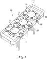
Figure 1 shows a millifluidic device for advanced cultures of biological agents, in a top perspective view, according to the present invention; -
Figure 2 shows a millifluidic device for advanced cultures of biological agents, in a perspective view from below, according to the present invention; -
Figure 3 shows a millifluidic device for advanced cultures of biological agents, without plugs, in a top perspective view, according to the present invention; -
Figure 4 shows a millifluidic device for advanced cultures of biological agents, without plugs and without separators, in a top perspective view, according to the present invention; -
Figure 5 shows a millifluidic device for advanced cultures of biological agents, in a perspective and sectional view, according to the present invention; -
Figure 6 shows, in a sectional view, a chamber of a millifluidic device for advanced cultures of biological agents, according to the present invention; -
Figure 7 shows a plug of a millifluidic device for advanced cultures of biological agents, in a top perspective view, according to the present invention; -
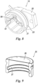
Figure 8 shows a plug of a millifluidic device for advanced cultures of biological agents, in a perspective view from below, according to the present invention; -
Figure 9 shows a separator of a millifluidic device for advanced cultures of biological agents, in a perspective and sectional view, according to the present invention; -
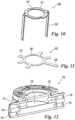
Figure 10 shows a first electrode of a millifluidic device for advanced cultures of biological agents according to the present invention; -
Figure 11 shows a second electrode of a millifluidic device for advanced cultures of biological agents, according to the present invention; -
Figure 12 shows a millifluidic device for advanced cultures of biological agents, in a perspective and sectional view, according to a first variant of the present invention; -
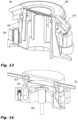
Figure 13 shows a millifluidic device for advanced cultures of biological agents, in a perspective and sectional view, according to a second variant of the present invention; -
Figure 14 shows a millifluidic device for advanced cultures of biological agents, in a perspective and sectional view, according to a third variant of the present invention. - With reference to the attached figures, a
device 10 for cell culture, according to the present invention, comprises a main rectangular-shaped body 11, with plan overall dimensions so that it can be housed in a slide holder for standard and confocal microscopy (for example: length from 60 mm to 80 mm, width from 20 to 30 mm, preferably length 68mm width 25 mm). - The
main body 11, as shown, comprises threechambers - The number of chambers can be varied from one to multiple according to the needs.
- The three
chambers elongated plug 15 that reaches the edges of thebody 11.Recesses 16 are arranged on the edge ofbody 11 in which the ends ofplug 15 are positioned in order to have a guide for the correct positioning of theplugs 15 themselves. - The
plugs 15 preferably comprise two through-holes 17, placed at the ends, in order to fix them firmly on thebody 11 by means of screws. Alternatively, other means for fixing theplugs 15 to thebody 11 can be used, such as, for example, hooks or pressure systems. - The
plugs 15 have a substantially flatupper component 20 and a cylindrical-shapedlower component 21. - A preferably circular-
shaped slide 22 is fixed on the upper and central component to theplug 15 which allows a complete view of the inside of the chamber, for use with microscopes. - An O-
ring seal 23 is arranged externally to thelower component 21. - Below the
body 11, two pairs of tubes can be seen for each chamber, which protrude perpendicular to thebody 11, and more specifically, exit from alower enlarging 24 of thebody 11 which provides space for the chambers 12-14. - A pair of
internal tubes 25, with an inlet tube and an outlet tube, for a first half-chamber (which we will define in the following) and a pair ofexternal tubes 26, with an inlet tube and an outlet tube, for a second half-chamber. - The threaded
holes 30 can be seen on thebody 11, which correspond to theholes 17 for fixing theplugs 15 onto thebody 11 by means ofscrews 27. - Once the
plugs 15 are removed theseparators 35 can be seen which allow each of the chambers 12-14 to be divided into two half-chambers. - The
separators 35 have a hollow cylindrical-shape open at the bottom and closed at the top by amembrane 36, to form an overturned glass-shape, closed at the top by themembrane 36. - The
membrane 36 divides the upper half-chamber from the lower half-chamber. - The
membrane 36 can be placed (glued) at the top of theseparators 35 as shown inFigures 3 and9 , but can be placed in positions inside theseparator 35 as shown inFigures 5 and6 , particularly at a predefined distance from the top of theseparator 35. - In particular, if the
membrane 36 is placed at the top of theseparators 35, the upper half-chamber is 0.3 mm high. In the case of other positioning of themembrane 36, aseparator 35 is made formed by two parts having pre-set heights. Themembrane 36 is glued onto the lower part of the separator and then the upper part of the separator is glued, thus positioning the membrane at the desired height and obtaining the two half-chambers having predefined heights. - The positioning of the
membrane 36 allows to increase or decrease the volume of the upper half-chamber and consequently decrease or increase the volume of the lower half-chamber. - An O-
ring seal 37 is placed inside theseparators 35, preferably in a position spaced from themembrane 36. - When the
separators 35 are removed, the prearranged areas for the chambers can be seen inbody 11. - For each chamber 12-14 there is a
hole 40 in thebody 11 closed at the bottom. At the centre of thehole 40, and coaxially thereto, acylindrical body 41 protrudes. A preferably circular-shapedslide 42 is placed at the top of thecylindrical body 41, which allows a complete view of the inside of the chamber, for use with microscopes. - The
slide 42 can be omitted if the materials used to make the device are transparent. - The inside of the
cylindrical body 41 is hollow and forms ahole 43, coaxial to thecylindrical body 41, which is open at the bottom and closed at the top by theslide 42. - The
hole 43 allows there to be less material in the optical path of the microscopes, thus allowing a better view of the inside of the half-chambers. - The
separator 35, including themembrane 36, is set in its place above thecylindrical body 41. - The
separator 35 can only be extracted from its place by opening theplug 15 and pulling it out, and it can be set again in its place by inserting it on top of thecylindrical body 41. - The pairs of
tubes hole 43 and transversely to thebody 11. - The device preferably comprises two electrically conductive electrodes, one for each half-chamber.
- The electrodes can be used both for measuring electrical parameters and for electrically stimulating the cultures contained in each culture chamber, such as, for example, for measuring the transepithelial/transendothelial resistance, for determining the onset of ionic currents passing through cell membranes, useful for physiological and neurobiological studies or for inducing tissue contraction, useful for simulating muscle contractions such as peristalsis.
- An
electrode 50 for the lower half-chamber has a main circular crown-shapedbody 51 with twobars 52 which extend from thecircular body 51 and are facing downwards, for electrical connection. - The
electrode 50 is placed above thecylindrical body 41 and thecircular body 51 is external to theslide 42 and in the area of the lower half-chamber. The twobars 52 protrude at the bottom from the body 11 (enlargement 24). - An
electrode 55 for the upper half-chamber has a main circular crown-shapedbody 56, and has somebars 57, to facilitate the positioning, and abar 58, longer than the previous ones for electrical connection, which extend from the circular body. - The
electrode 55 is placed in a housing on theplug 15, and thecircular body 56 is external to and below theslide 22, so that it is positioned in the area of the upper half-chamber. - The
electrodes - Each half-chamber is sealed and isolated and communicates with the outside only with the pairs of
tubes membrane 36 determines the permeability between the two half-chambers. For example, it is possible to insert membranes made of polycarbonate, PET, PVC, TEFLON, PDMS, cellulose acetate, polyester, polystyrene, nylon, with a pre-defined porosity. - The
internal seal 37 of theseparators 35 interferes with the external lateral surface of thecylindrical body 41, and closes the lower half-chamber, delimited at the top by themembrane 36, at the bottom by theslide 42 and at the sides by theseparator 35. - The
external seal 23 of theplug 15 interferes with the internal lateral surface of thehole 40, and closes the upper half-chamber, delimited at the top by theslide 22, at the bottom by themembrane 36 and at the sides by thelower component 21 of theplug 15 or by theseparator 35. - The
cylindrical body 41, which emerges from thehole 40, forms abase 45, around thecylindrical body 41, with a circular crown-shape that acts as the lower reference abutment for both the plug 15 (lower component 21) and the base of theseparator 35. - Therefore, after the opening of the
plug 15 and the extraction of theseparator 35, when they have to be inserted again, both are positioned correctly as in the original position. - The perfusion of the chambers takes place via the pairs of
tubes - The upper half-chamber uses the outermost pair of
tubes 26. They are fixed in ahole 60 of thebody 11 and reach thebase 45 and are aligned with the line where theseparator 35 and theplug 15 are arranged side-by-side. - Between the
separator 35 and the plug 15 a passage is prearranged that reaches the upper half-chamber. This passage is a pair ofgrooves 61 prearranged on the internal lateral wall of theplug 15 and, to facilitate the inflow inside the half-chamber, the groove also partially continues on the upper internal wall of theplug 15 until it reaches theslide 22 and/or theelectrode 55. - This fluid path can also be conveniently made by means of metal tubes connected to the plug and integral thereto and which are close to or, better still, engage directly in the internal lumen of the
tubes 26 once the device has been assembled. - The lower half-chamber uses the innermost pair of
tubes 25. They are fixed in ahole 65, side-by-side to the internal wall of theseparator 35 and reaches a through-hole 66, between the external edge of theseparator 35 and theslide 42. - If the
electrode 50 is present, it has abevelling 67 at thehole 66 to allow the perfusion flow. - The
electrodes - In one embodiment of the device, the
body 11 has a size of 25x68 mm, the half-chambers (upper and lower) have an average diameter comprised between 5 and 12 mm (preferably 10 mm) and a depth comprised between 0.3 mm and 1.8 mm (preferably 0.3 mm for the upper half-chamber and 1.8 mm for the lower half-chamber). In this case themembrane 36 has been placed above theseparator 35. Thedevice 10 can be used for the culture of cells derived from living organisms both of the immortalised type (i.e. able to replicate indefinitely in culture) and of the primary type (i.e. with a limited or no capacity to replicate in culture), both in suspension and adhesion, in 2D and hosted in 3D in appropriate polymeric mediums and matrices. It may also be adapted for incubating parts derived from cells (e.g. microvesicles or particular cellular organelles), as well as for bacteria or solutions containing chemical molecules, including drugs. - It can also be used to combine a culture, for example neurons or endothelial cells or specific bacteria, grown individually or in co-culture such as in the intestinal microbiota, in one half-chamber, and a culture in the other half-chamber, such as, for example, astrocytes or blood cells or endothelial cells of the intestine to analyse how their interaction is of physiological or pathological relevance.
- According to a first variant of the present invention, the device is now shown as a single device but could be structured, as in the previous case, with two or more devices placed in a single body.
- In this case the
single device 70 has a substantiallycircular body 71, and comprises anextractable separator 72, formed by a circular disc to the bottom of which amembrane 73 is fixed, which divides thebody 71 into two half-chambers, one upper and one lower. Theseparator 72, when inserted in thebody 71, rests on an edge arranged inbody 71 itself. - The
perfusion channels body 71, access the two half-chambers at the sides and are parallel to the membrane. The connection tubes (not shown) can possibly be applied to thechannels - The
device 70 can be used on its own or can be used in combination with thedevice 10. - In particular it is possible to cultivate, in the
device 70, a bacterial culture placed in a half-chamber, fed by a fermenter or a bacterial culture in a suitable container, potentially also connected to a device that allows the mixing of bacteria in a polymeric matrix that simulates, for example, the intestinal mucus in the case of bacterial culture in 3D; the resulting secretome, namely, the set of molecules produced by the resulting culture, is transferred through the membrane into the other half-chamber and is sent to one or more chambers of thedevice 10 to verify the impact of the molecules produced on particular organs and biological systems, under physiological or pathological conditions including, by way of example but not limited to: intestinal endothelium: liver; immune system; blood-brain barrier; brain. In this case a porous membrane is used with a molecular cleaving that allows the passage of substances but not of cells (typically 0.1 micrometers between bacteria and secretome and 0.4 for the other half-chambers hosting cell cultures). - According to a second variant of the present invention, the perfusion of the lower half-chamber takes place as previously described from the
tubes 82 coming from below and placed inside the device, while the perfusion of the upper half-chamber takes place throughtubes 83 placed in theplug 84. The half-chambers are separated by themembrane 81 supported by a smallcylindrical element 80, which may also be of the already commercially available type. For example, it is possible to use chambers compatible with Transwell type cell culture inserts produced by Greiner Bio-One International GmbH, both with translucent and transparent membranes. - According to a third variant of the present invention, perfusion of the lower half-chamber takes place by means of
tubes 90 placed below the device, the perfusion of the upper half-chamber takes place by means oftubes 91 placed in the plug, and the two half-chambers are separated by aseparator 92 supporting amembrane 93. - All the components are made of plastic and elastomeric materials and are designed to be manufactured by injection moulding of plastic materials or other manufacturing method that can be applied on an industrial scale.
- The materials as well as the dimensions and shapes used can be of any type according to the needs and the state of the art. For example, the chambers and all the connected elements have been made in a circular shape but nothing prevents them from being made in other shapes such as square or oval.
- In another possible embodiment, the device is made with individual chambers, which can be divided to host inserts and membranes that are commercially available and already used in the biological field for cell cultures. Both the lower and upper parts of these chambers contain a suitable gasket (e.g. OR) such as to interact with the commercial insert and guarantee sufficient hydraulic sealing to be able to perfuse the two sides of the membrane, according to the configuration of the channels described above and the possible combinations of devices. These individual chambers are also provided with the connection via screws or other mechanical means, suitable to avoid the division of the chamber under the pressure exerted by the perfusion fluid. These individual chambers are optically accessible as previously described for other configurations of the device. These individual chambers can be inserted in a suitable housing that can contain several chambers and can be housed in a microscope suitable to inspect the perfused culture through the optical accesses obtained in each chamber. These individual chambers can house electrodes as previously described for the other configurations and can also be easily connected to one another or to other millifluidic or microfluidic devices, in both series and parallel configuration.
Claims (11)
- A millifluidic device for cultures of biological agents comprising:a main body (11) comprising at least a chamber (12-14) with an independent hydraulic circuit with a first hole (40) closed at the bottom and provided with a plug (15);a separator (35) designed to be placed in said first hole (40) and which allow said chamber (12-14) to be divided into an upper half-chamber and a lower half-chamber;a membrane (36) fixed to said separator (35) to divides said upper half-chamber from said lower half-chamber;said separator (35) being extractable from said first hole (40) once the plug (15) is removed;a pair of tubes (25) to perfuse said lower half-chamber;a pair of tubes (26) to perfuse said upper half-chamber;a first slide (22) placed concentrically on said plug (15);a second slide (42) placed concentrically on said first hole (40);a cylindrical body (41) rises coaxially from said first hole (40) toward said lower half-chamber;said second slide (42) is placed on the top of said cylindrical body (41);said first hole (40) is closed at the bottom by said second slide (42);said cylindrical body (41) has a second hole (43), coaxial to said cylindrical body (41);said pairs of tubes (25) and (26) are laterally aligned with said hole (43) and transversely to said body (11);the lower half-chamber, is delimited at the top by the membrane (36), at the bottom by the slide (42) and at the sides by the separator (35);the upper half-chamber, is delimited at the top by the slide (22), at the bottom by the membrane (36) and at the sides by a lower component (21) of the plug (15) or by the separator (35).
- The device according to claim 1 characterised in that said membrane (36) is chosen between a permeable, a waterproof or a semi-permeable membrane.
- The device according to claim 1 characterised in that said membrane (36) is made of one or more of the following materials: polycarbonate, PET, PVC, TEFLON, PDMS, cellulose acetate, polyester, polystyrene, nylon.
- The device according to claim 1 characterised in that said membrane (36) is placed at the top of said separator (35).
- The device according to claim 1 characterised in that said membrane (36) is placed at a predefined distance from the top of said separator (35).
- The device according to claim 1 characterised in that it comprises a first conductive electrode (50) for said lower half-chamber, which has a main circular crown-shaped body (51), therefore with a central hole; the electrode (50) is placed above the cylindrical body (41) and the crown-shaped body (51) is external to the slide (42) and in the area of the lower half-chamber.
- The device according to claim 1 characterised in that it comprises a second conductive electrode (55) for said upper half-chamber, which has a main circular crown-shaped body (56), therefore with a central hole; the electrode (55) is placed in a housing on the plug (15), and the crown-shaped body body (56) is external to and below the slide (22), so that it is positioned in the area of the upper half-chamber.
- The device according to claim 1 characterised in that said upper half-chamber is fluidodynamically isolated from said lower half-chamber, only the type of membrane determines the permeability between said two half-chambers.
- The device according to claim 1 characterised in that said separator (35) has a hollow cylindrical shape open at the bottom and closed at the top by a membrane (36).
- The device according to claim 1 characterised in that said cylindrical body (41) has a base (45) with a circular crown-shaped body that acts as a lower reference abutment for both the plug (15) and the separator (35).
- A use of the millifluidic device for cultures of biological agents according to claim 1 for the cell culture of immortalised or primary cells or bacteria both in suspension and adhesion, in 2D or 3D, for the creation of perfused solutions containing parts derived from cells (e.g. microvesicles or organelles), or biological molecules (e.g. protein or isolated DNA) or even bioactive molecules (e.g. drugs).
Applications Claiming Priority (2)
| Application Number | Priority Date | Filing Date | Title |
|---|---|---|---|
| IT102019000016376A IT201900016376A1 (en) | 2019-09-16 | 2019-09-16 | MILLIFLUIDIC DEVICE FOR ADVANCED CROPS OF BIOLOGICAL AGENTS |
| PCT/IB2020/058339 WO2021053458A1 (en) | 2019-09-16 | 2020-09-08 | Millifluidic device for advanced cultures of biological agents |
Publications (3)
| Publication Number | Publication Date |
|---|---|
| EP4031646A1 EP4031646A1 (en) | 2022-07-27 |
| EP4031646C0 EP4031646C0 (en) | 2025-04-30 |
| EP4031646B1 true EP4031646B1 (en) | 2025-04-30 |
Family
ID=69375733
Family Applications (1)
| Application Number | Title | Priority Date | Filing Date |
|---|---|---|---|
| EP20781074.8A Active EP4031646B1 (en) | 2019-09-16 | 2020-09-08 | Millifluidic device for advanced cultures of biological agents |
Country Status (9)
| Country | Link |
|---|---|
| US (1) | US12467028B2 (en) |
| EP (1) | EP4031646B1 (en) |
| JP (1) | JP7555402B2 (en) |
| CN (1) | CN114514310A (en) |
| AU (1) | AU2020349664B2 (en) |
| CA (1) | CA3150446A1 (en) |
| ES (1) | ES3036124T3 (en) |
| IT (1) | IT201900016376A1 (en) |
| WO (1) | WO2021053458A1 (en) |
Families Citing this family (1)
| Publication number | Priority date | Publication date | Assignee | Title |
|---|---|---|---|---|
| IT202300012753A1 (en) * | 2023-06-20 | 2024-12-20 | Milano Politecnico | MULTIFUNCTIONAL SENSORIZED DEVICE FOR ORGANIC CROPS |
Family Cites Families (10)
| Publication number | Priority date | Publication date | Assignee | Title |
|---|---|---|---|---|
| DK3327110T3 (en) | 2011-11-07 | 2020-04-27 | Rapid Micro Biosystems Inc | Kassette til sterilitetstest |
| EP2913389A1 (en) * | 2014-02-28 | 2015-09-02 | Institut d'Investigacions Biomédiques August Pi i Sunyer | Bioreactor for cell co-culture |
| US9527077B2 (en) * | 2015-01-29 | 2016-12-27 | David W. Wright | Diagnostic cartridge, fluid storage and delivery apparatus therefor and methods of construction thereof |
| US9901921B2 (en) * | 2015-05-28 | 2018-02-27 | David W. Wright | Disposable invitro diagnostic cartridge and method of performing an invitro diagnostic test |
| CA3006063A1 (en) * | 2015-11-24 | 2017-06-01 | Vanderbilt University | Multicompartment layered and stackable microfluidic bioreactors and applications of same |
| US10408821B2 (en) * | 2016-04-14 | 2019-09-10 | Triad National Security, Llc | Microfluidic aspirator and methods of making and using the same |
| ITUA20163336A1 (en) | 2016-05-11 | 2017-11-11 | Fincantieri Spa | METHOD OF CHLORINATION OF DRINKING WATER ON A SHIP, IN PARTICULAR A PASSENGER SHIP |
| ITUA20163547A1 (en) * | 2016-05-18 | 2017-11-18 | Milano Politecnico | DEVICE FOR CELL CULTURE |
| SG10201606627QA (en) | 2016-08-10 | 2018-03-28 | Agency Science Tech & Res | Microfluidic chip |
| BR102017004855A2 (en) * | 2017-03-10 | 2018-10-30 | Soc Beneficente Israelita Brasileira Hospital Albert Einstein | dynamic cell culture system |
-
2019
- 2019-09-16 IT IT102019000016376A patent/IT201900016376A1/en unknown
-
2020
- 2020-09-08 AU AU2020349664A patent/AU2020349664B2/en active Active
- 2020-09-08 WO PCT/IB2020/058339 patent/WO2021053458A1/en not_active Ceased
- 2020-09-08 JP JP2022516613A patent/JP7555402B2/en active Active
- 2020-09-08 CA CA3150446A patent/CA3150446A1/en active Pending
- 2020-09-08 EP EP20781074.8A patent/EP4031646B1/en active Active
- 2020-09-08 ES ES20781074T patent/ES3036124T3/en active Active
- 2020-09-08 US US17/760,811 patent/US12467028B2/en active Active
- 2020-09-08 CN CN202080064852.0A patent/CN114514310A/en active Pending
Also Published As
| Publication number | Publication date |
|---|---|
| EP4031646C0 (en) | 2025-04-30 |
| EP4031646A1 (en) | 2022-07-27 |
| CA3150446A1 (en) | 2021-03-25 |
| JP7555402B2 (en) | 2024-09-24 |
| US12467028B2 (en) | 2025-11-11 |
| WO2021053458A1 (en) | 2021-03-25 |
| US20220340854A1 (en) | 2022-10-27 |
| CN114514310A (en) | 2022-05-17 |
| AU2020349664B2 (en) | 2026-02-19 |
| JP2022549094A (en) | 2022-11-24 |
| AU2020349664A1 (en) | 2022-03-31 |
| ES3036124T3 (en) | 2025-09-12 |
| IT201900016376A1 (en) | 2021-03-16 |
Similar Documents
| Publication | Publication Date | Title |
|---|---|---|
| KR101717814B1 (en) | Cell culture insert | |
| CN1875093B (en) | Cell Culture Equipment and Methods of Use | |
| JP6845228B2 (en) | Microfluidic device for in vitro 3D cell culture experiments | |
| US10272433B2 (en) | Vertical functional reaction vessel | |
| KR20240052713A (en) | Microfluidic cell culture device and cell culture method | |
| WO2017062609A1 (en) | Multiwell culture devices with perfusion and oxygen control | |
| WO2022116406A1 (en) | Open-type co-culture organ-on-a-chip and use thereof | |
| US12467028B2 (en) | Millifluidic device for advanced cultures of biological agents | |
| US7897377B2 (en) | Cell- and tissue culture device | |
| WO2018106132A1 (en) | Microfluidic device for cell culture in gradient of bioactive substance | |
| EP3458193B1 (en) | A device for cell culture | |
| HK40067665A (en) | Millifluidic device for advanced cultures of biological agents | |
| US9012205B2 (en) | Revolving cell culture cartridge and methods of use | |
| CN203429184U (en) | Multi-adherent-cell coculture device | |
| CN111500445A (en) | High-flux multi-organ chip and using method thereof | |
| EP4480580A1 (en) | A fluidic device | |
| CN223813514U (en) | A microfluidic device for cell experiments | |
| CN222834326U (en) | Array cell culture chip structure | |
| US20260103666A1 (en) | Three-dimensional cell culture device | |
| WO2022019739A1 (en) | Insert based on a resealable organ on a chip platform | |
| RU2583310C1 (en) | Port for feeding test chemical compound and withdrawal of fluid from cells for cultivation of cell models | |
| CN119685162A (en) | Microfluidic device and method for cell experiment |
Legal Events
| Date | Code | Title | Description |
|---|---|---|---|
| STAA | Information on the status of an ep patent application or granted ep patent |
Free format text: STATUS: UNKNOWN |
|
| STAA | Information on the status of an ep patent application or granted ep patent |
Free format text: STATUS: THE INTERNATIONAL PUBLICATION HAS BEEN MADE |
|
| PUAI | Public reference made under article 153(3) epc to a published international application that has entered the european phase |
Free format text: ORIGINAL CODE: 0009012 |
|
| STAA | Information on the status of an ep patent application or granted ep patent |
Free format text: STATUS: REQUEST FOR EXAMINATION WAS MADE |
|
| 17P | Request for examination filed |
Effective date: 20220331 |
|
| AK | Designated contracting states |
Kind code of ref document: A1 Designated state(s): AL AT BE BG CH CY CZ DE DK EE ES FI FR GB GR HR HU IE IS IT LI LT LU LV MC MK MT NL NO PL PT RO RS SE SI SK SM TR |
|
| DAV | Request for validation of the european patent (deleted) | ||
| DAX | Request for extension of the european patent (deleted) | ||
| P01 | Opt-out of the competence of the unified patent court (upc) registered |
Effective date: 20230615 |
|
| STAA | Information on the status of an ep patent application or granted ep patent |
Free format text: STATUS: EXAMINATION IS IN PROGRESS |
|
| 17Q | First examination report despatched |
Effective date: 20240315 |
|
| GRAP | Despatch of communication of intention to grant a patent |
Free format text: ORIGINAL CODE: EPIDOSNIGR1 |
|
| STAA | Information on the status of an ep patent application or granted ep patent |
Free format text: STATUS: GRANT OF PATENT IS INTENDED |
|
| RIC1 | Information provided on ipc code assigned before grant |
Ipc: C12M 3/06 20060101ALI20250129BHEP Ipc: C12M 1/34 20060101ALI20250129BHEP Ipc: C12M 1/42 20060101ALI20250129BHEP Ipc: C12M 3/00 20060101ALI20250129BHEP Ipc: B01L 3/00 20060101ALI20250129BHEP Ipc: B01L 9/00 20060101ALI20250129BHEP Ipc: C12M 1/00 20060101AFI20250129BHEP |
|
| INTG | Intention to grant announced |
Effective date: 20250211 |
|
| GRAS | Grant fee paid |
Free format text: ORIGINAL CODE: EPIDOSNIGR3 |
|
| GRAA | (expected) grant |
Free format text: ORIGINAL CODE: 0009210 |
|
| STAA | Information on the status of an ep patent application or granted ep patent |
Free format text: STATUS: THE PATENT HAS BEEN GRANTED |
|
| AK | Designated contracting states |
Kind code of ref document: B1 Designated state(s): AL AT BE BG CH CY CZ DE DK EE ES FI FR GB GR HR HU IE IS IT LI LT LU LV MC MK MT NL NO PL PT RO RS SE SI SK SM TR |
|
| REG | Reference to a national code |
Ref country code: CH Ref legal event code: EP Ref country code: GB Ref legal event code: FG4D |
|
| REG | Reference to a national code |
Ref country code: IE Ref legal event code: FG4D |
|
| REG | Reference to a national code |
Ref country code: DE Ref legal event code: R096 Ref document number: 602020050487 Country of ref document: DE |
|
| U01 | Request for unitary effect filed |
Effective date: 20250519 |
|
| U07 | Unitary effect registered |
Designated state(s): AT BE BG DE DK EE FI FR IT LT LU LV MT NL PT RO SE SI Effective date: 20250526 |
|
| P04 | Withdrawal of opt-out of the competence of the unified patent court (upc) registered |
Free format text: CASE NUMBER: APP_24361/2025 Effective date: 20250521 |
|
| U20 | Renewal fee for the european patent with unitary effect paid |
Year of fee payment: 6 Effective date: 20250710 |
|
| REG | Reference to a national code |
Ref country code: ES Ref legal event code: FG2A Ref document number: 3036124 Country of ref document: ES Kind code of ref document: T3 Effective date: 20250912 |
|
| PG25 | Lapsed in a contracting state [announced via postgrant information from national office to epo] |
Ref country code: NO Free format text: LAPSE BECAUSE OF FAILURE TO SUBMIT A TRANSLATION OF THE DESCRIPTION OR TO PAY THE FEE WITHIN THE PRESCRIBED TIME-LIMIT Effective date: 20250730 Ref country code: GR Free format text: LAPSE BECAUSE OF FAILURE TO SUBMIT A TRANSLATION OF THE DESCRIPTION OR TO PAY THE FEE WITHIN THE PRESCRIBED TIME-LIMIT Effective date: 20250731 |
|
| PG25 | Lapsed in a contracting state [announced via postgrant information from national office to epo] |
Ref country code: PL Free format text: LAPSE BECAUSE OF FAILURE TO SUBMIT A TRANSLATION OF THE DESCRIPTION OR TO PAY THE FEE WITHIN THE PRESCRIBED TIME-LIMIT Effective date: 20250430 |
|
| PGFP | Annual fee paid to national office [announced via postgrant information from national office to epo] |
Ref country code: GB Payment date: 20250929 Year of fee payment: 6 |
|
| PG25 | Lapsed in a contracting state [announced via postgrant information from national office to epo] |
Ref country code: HR Free format text: LAPSE BECAUSE OF FAILURE TO SUBMIT A TRANSLATION OF THE DESCRIPTION OR TO PAY THE FEE WITHIN THE PRESCRIBED TIME-LIMIT Effective date: 20250430 |
|
| PG25 | Lapsed in a contracting state [announced via postgrant information from national office to epo] |
Ref country code: RS Free format text: LAPSE BECAUSE OF FAILURE TO SUBMIT A TRANSLATION OF THE DESCRIPTION OR TO PAY THE FEE WITHIN THE PRESCRIBED TIME-LIMIT Effective date: 20250731 |
|
| PG25 | Lapsed in a contracting state [announced via postgrant information from national office to epo] |
Ref country code: IS Free format text: LAPSE BECAUSE OF FAILURE TO SUBMIT A TRANSLATION OF THE DESCRIPTION OR TO PAY THE FEE WITHIN THE PRESCRIBED TIME-LIMIT Effective date: 20250830 |
|
| REG | Reference to a national code |
Ref country code: CH Ref legal event code: U11 Free format text: ST27 STATUS EVENT CODE: U-0-0-U10-U11 (AS PROVIDED BY THE NATIONAL OFFICE) Effective date: 20251230 |
|
| PG25 | Lapsed in a contracting state [announced via postgrant information from national office to epo] |
Ref country code: SM Free format text: LAPSE BECAUSE OF FAILURE TO SUBMIT A TRANSLATION OF THE DESCRIPTION OR TO PAY THE FEE WITHIN THE PRESCRIBED TIME-LIMIT Effective date: 20250430 |
|
| PGFP | Annual fee paid to national office [announced via postgrant information from national office to epo] |
Ref country code: CH Payment date: 20251230 Year of fee payment: 6 |
|
| PG25 | Lapsed in a contracting state [announced via postgrant information from national office to epo] |
Ref country code: CZ Free format text: LAPSE BECAUSE OF FAILURE TO SUBMIT A TRANSLATION OF THE DESCRIPTION OR TO PAY THE FEE WITHIN THE PRESCRIBED TIME-LIMIT Effective date: 20250430 |
|
| PG25 | Lapsed in a contracting state [announced via postgrant information from national office to epo] |
Ref country code: SK Free format text: LAPSE BECAUSE OF FAILURE TO SUBMIT A TRANSLATION OF THE DESCRIPTION OR TO PAY THE FEE WITHIN THE PRESCRIBED TIME-LIMIT Effective date: 20250430 |
|
| PGFP | Annual fee paid to national office [announced via postgrant information from national office to epo] |
Ref country code: ES Payment date: 20251002 Year of fee payment: 6 |
|
| PLBE | No opposition filed within time limit |
Free format text: ORIGINAL CODE: 0009261 |
|
| STAA | Information on the status of an ep patent application or granted ep patent |
Free format text: STATUS: NO OPPOSITION FILED WITHIN TIME LIMIT |
|
| REG | Reference to a national code |
Ref country code: CH Ref legal event code: L10 Free format text: ST27 STATUS EVENT CODE: U-0-0-L10-L00 (AS PROVIDED BY THE NATIONAL OFFICE) Effective date: 20260311 |
|
| 26N | No opposition filed |
Effective date: 20260202 |