EP4031459B1 - Ventil für einen verpackungsbehälter - Google Patents
Ventil für einen verpackungsbehälter Download PDFInfo
- Publication number
- EP4031459B1 EP4031459B1 EP20775845.9A EP20775845A EP4031459B1 EP 4031459 B1 EP4031459 B1 EP 4031459B1 EP 20775845 A EP20775845 A EP 20775845A EP 4031459 B1 EP4031459 B1 EP 4031459B1
- Authority
- EP
- European Patent Office
- Prior art keywords
- film
- membrane
- frame
- valve according
- base film
- Prior art date
- Legal status (The legal status is an assumption and is not a legal conclusion. Google has not performed a legal analysis and makes no representation as to the accuracy of the status listed.)
- Active
Links
Images

Classifications
-
- B—PERFORMING OPERATIONS; TRANSPORTING
- B65—CONVEYING; PACKING; STORING; HANDLING THIN OR FILAMENTARY MATERIAL
- B65D—CONTAINERS FOR STORAGE OR TRANSPORT OF ARTICLES OR MATERIALS, e.g. BAGS, BARRELS, BOTTLES, BOXES, CANS, CARTONS, CRATES, DRUMS, JARS, TANKS, HOPPERS, FORWARDING CONTAINERS; ACCESSORIES, CLOSURES, OR FITTINGS THEREFOR; PACKAGING ELEMENTS; PACKAGES
- B65D77/00—Packages formed by enclosing articles or materials in preformed containers, e.g. boxes, cartons, sacks or bags
- B65D77/22—Details
- B65D77/225—Pressure relief-valves incorporated in a container wall, e.g. valves comprising at least one elastic element
-
- B—PERFORMING OPERATIONS; TRANSPORTING
- B65—CONVEYING; PACKING; STORING; HANDLING THIN OR FILAMENTARY MATERIAL
- B65D—CONTAINERS FOR STORAGE OR TRANSPORT OF ARTICLES OR MATERIALS, e.g. BAGS, BARRELS, BOTTLES, BOXES, CANS, CARTONS, CRATES, DRUMS, JARS, TANKS, HOPPERS, FORWARDING CONTAINERS; ACCESSORIES, CLOSURES, OR FITTINGS THEREFOR; PACKAGING ELEMENTS; PACKAGES
- B65D33/00—Details of, or accessories for, sacks or bags
- B65D33/01—Ventilation or drainage of bags
-
- B—PERFORMING OPERATIONS; TRANSPORTING
- B65—CONVEYING; PACKING; STORING; HANDLING THIN OR FILAMENTARY MATERIAL
- B65D—CONTAINERS FOR STORAGE OR TRANSPORT OF ARTICLES OR MATERIALS, e.g. BAGS, BARRELS, BOTTLES, BOXES, CANS, CARTONS, CRATES, DRUMS, JARS, TANKS, HOPPERS, FORWARDING CONTAINERS; ACCESSORIES, CLOSURES, OR FITTINGS THEREFOR; PACKAGING ELEMENTS; PACKAGES
- B65D2205/00—Venting means
Definitions
- the present invention relates to a valve, in particular a pressure relief valve for a packaging container, according to the preamble of the independent claim.
- valves are used in packaging technology when the contents tend to outgas, such as freshly roasted coffee.
- the EP760790B1 a pressure relief valve for a packaging container with a base plate attached to the wall of the packaging container, which has a central valve hole covering a through hole in the wall of the packaging container, and with a valve membrane attached to the base plate with two parallel edge zones, leaving a channel zone free, which covers the valve hole and lies tightly on the base plate in the closed position.
- the valve hole is formed from at least two intersecting, circular openings.
- a pressure relief valve of this type is known, which comprises a base body with a two-stage recess and a membrane, wherein the membrane has a deformable surface directed towards a sealing surface.
- the base body has a relatively complex structure.
- EP 1 538 107 A2 , US 6 662 827 B1 and US 2012/243807 A1 Valves for a packaging container which comprise a base element with an opening and at least one frame element which surrounds a free area, wherein the frame element is connected to the base element, wherein at least one membrane is provided which is arranged on the base element and covers the opening, wherein a fluid is provided between the membrane and the base element, wherein the membrane is movably arranged within the free area on the base element.
- the valve according to the invention for a packaging container has the advantage that the valve can be produced more easily. In addition, the function of the valve is improved. The valve is also characterized by reduced manufacturing costs.
- the basic structure of the valve can be applied both outside the packaging container and, in a certain design variant, inside the packaging container. This is made possible according to the invention by the fact that the membrane is arranged on a base film so that it is at least partially floating or freely movable within the free area. The membrane is therefore no longer connected to the base body over a large area and is therefore significantly less affected by external influences such as warping.
- the proposed structure of base film, frame film and, if applicable, cover film results in high flexural rigidity with comparatively little material usage.
- the valve combines the good valve properties of an injection-molded valve with those of a film valve. It offers very low opening and closing pressures.
- the valve is constructed from several film layers, which are produced, for example, on rotary punching tools and then laminated to one another. Ideally, the joining is done by welding. Alternatively, an adhesion promoter such as glue could be used.
- the proposed valve can preferably be made from a single type of material and is therefore easier to recycle and thus more environmentally friendly or easier to weld.
- the film is made of polypropylene. However, renewable materials such as plastics made from renewable raw materials or biodegradable plastics would also be possible.
- the frame film is designed in such a way that it surrounds the membrane so that the membrane cannot leave the free area.
- the frame foil has at least one interruption, so that a channel is initially formed.
- Providing just one interruption ensures that the frame film can preferably be made in one piece. This makes handling and applying the frame film easier.
- the free area is circular in shape with a radius that is larger than the radius of the circular membrane. This arrangement is particularly easy to manufacture and also ensures that the membrane can move freely enough. It is particularly preferred that the thickness of the frame film is larger than the thickness of the membrane so that the membrane can be reliably lifted off the opening.
- the thickness of the frame film is greater than the thickness of the membrane, preferably 75% to 225% greater. This enables the membrane to be lifted off particularly safely.
- At least one cover film is provided which is connected to the frame film. Especially in the case of an external valve, this protects the membrane from environmental influences and ensures that the membrane cannot completely lift off and be separated from the base body or get lost.
- the base film and/or the frame film and/or the cover film are made of polypropylene, OPP, PET, polyolefin or plastic, preferably from renewable raw materials or biodegradable plastics. This can increase recyclability and environmental compatibility.
- the frame film and/or base film and/or cover film are connected via a welded joint, in particular laminated. This means that unwanted adhesive can be dispensed with in the manufacturing process due to increased cleaning requirements, which is also expensive. With an internal valve, this avoids adhesive being on the side facing the product.
- the base film has a thickness between 0.1 mm and 0.25 mm, in particular 0.125 mm and/or the frame film has a thickness of between 0.1 mm and 0.2 mm and/or the cover film has a thickness of between 0.05 mm and 0.15 mm, in particular 0.1 mm, and/or the membrane has a thickness of between 0.025 mm and 0.075 mm, in particular 0.05 mm.
- Such film thicknesses are particularly suitable for good manufacturability and, in conjunction with other geometries, are suitable for setting preferred opening pressures for this field of application.
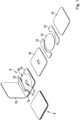
- FIG. 1 shows the individual components of a valve 8 according to a first embodiment.
- the valve 8 comprises a base film 10.
- the base film 10 is provided with an opening 11.
- the opening 11 has the geometry of two intersecting circles.
- any other geometries are conceivable. It is particularly preferred that the geometry be adapted to the desired opening and closing pressures.
- at least one frame film 13 is provided.
- the frame film 13 is designed such that a membrane 12 is at least partially surrounded, but captively.
- the frame film 13 has a free area 17 in which the membrane 12 is arranged. In the assembled state, the membrane 12 lies between the two parts of the frame film 13 in the embodiment.
- a cover film 15 is also provided.
- a fluid or fluid film for example silicone oil, also biological fluids such as palm oil, coconut oil or the like, is located between the base film 10 and the membrane 12.
- the membrane 12 is also designed as a film.
- the membrane 12 covers the opening 11. To allow excess pressure to escape from the packaging, the membrane 12 can lift off from the opening 11 so that excess pressure in the packaging can be released to the outside.
- the embodiment according to Figure 1 has a rectangular, preferably square basic shape.
- the base film 10 and the cover film 15 are rectangular, in particular square.
- the outer sides of the frame film 13 are aligned with the base film 10 and cover film 15 arranged below and above it.
- the membrane 12 is circular and arranged centrally to the opening 11.
- the inner sides of the frame film 15 are at least partially circular, so that a constant distance to the membrane 12 is established. This forms the circular free area 17.
- the frame foil 15 encloses the membrane 12 from at least two sides. This forms two channels 18 through which the excess pressure can escape.
- the width of the channel 18 is smaller than the diameter of the membrane 12. This ensures that the membrane 12 remains within the frame foil 13.
- Other geometries of the frame foil 15 are also conceivable.
- the frame foil 15 with only one channel 18, since the frame foil 15 is formed in one piece.
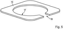
- This is exemplified in Figure 5 shown, with a free area 17 of the frame film 15 being open on one side via only one channel 18.
- the channel 18 runs parallel to the side surfaces. It is essential that the frame film 15 is designed in such a way that the membrane 12 arranged between the base film 10 and the cover film 15 (or the packaging wall in the case of an internal valve 8) cannot leave this area. For this purpose, the membrane 12 remains in the free area 17.
- the valve 8 is constructed from several film layers. In the embodiment according to Figure 1 These are the base film 10, the membrane 12, the frame film 13 and (optionally for external valves 8) the cover film 15. To produce the assembled valve 8, the film layers are produced, for example, on punching tools, in particular rotary punching tools, and then laminated. The film layers are preferably joined by a welded connection. Suitable welding processes are used to introduce the heat input suitable for the corresponding film thicknesses, so that a firm connection of the various film layers (base film 10, frame film 13, optionally cover film 15) is achieved. Alternatively, the joining can be carried out using an adhesion promoter (adhesive).
- an adhesion promoter adheresive
- the membrane 12 lies loosely on the base film 10.
- the membrane 12 is connected to the base film 10 in a floating manner via a fluid (not shown) arranged between the base film 10 and the membrane.
- the fluid causes the membrane 12 to lie tightly against the base film 10 through capillary forces and to seal the opening 11 gas-tight, but can lift off in the event of excess pressure.
- the sealing surface is thus the fluid film between the membrane 12 and the base film 10.
- the membrane 12 is introduced into the free area 17, surrounded by the frame film 13.
- the frame film 13 surrounds the membrane 12. The frame film 13 ensures the position of the membrane 12.
- FIG 2 another embodiment of the valve 8 is shown. It is characterized by a circular geometry.
- the circular base film 10 has a centrally arranged opening 11.
- the opening 11 is circular.
- the frame film 13 consists of four partial films.
- the partial films of the frame film 13 are each identically designed and are flush with the outer contour of the base film 10 at the edges.
- the frame film 13 encloses the free area 17 in which the membrane 12 is arranged.
- the width of the partial films of the frame film 13 is constant, so that the edge oriented towards the membrane 12 is also circular.
- the partial films of the frame film 13 surround the membrane 12.
- the membrane 12 is circular.
- the four partial films form a total of four channels 18 between two adjacent partial films.
- the valve 8 is designed as an external valve, i.e. it is attached to the outside of the packaging.
- the cover film 15 is provided to protect the membrane 12.
- the cover film 15 is circular and is connected to the frame film 13. It corresponds to the contour of the base film 10.
- the outer edges of the base film 10, frame film 13 and cover film 15 are aligned.
- a fluid film is provided between the base film 10 and the membrane 12. Again, the thin membrane 12 lies loosely on the base film 10 in the free area 17. The fluid is located between them.
- the four channels 18 establish a connection to the environment between the free area 17 inside the valve 8.
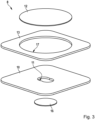
- the embodiment according to Figure 3 shows an internal valve 8, so the valve 8 is arranged on the inside of the packaging.
- the valve 8 in turn consists of a base film 10.
- the base film 10 has at least one opening 11.
- the frame film 13 is arranged on the base film 10.
- the frame film 13 has a closed edge that completely surrounds the membrane 12.
- the area thus delimited is the circular free area 17. This means that no channels 18 are formed on the sides.
- the membrane 12 is arranged loosely on the base film 10, specifically in the free area 17.
- a fluid film is provided between the membrane 12 and the base film 10.
- the other side of the opening 11 is covered by a filter 16, in particular a filter fleece 16.
- the filter 16 or fleece is required to prevent particles of the filling material from penetrating the valve 8 between the membrane 12 and the base film 10, which would impair the function.
- the filter 16 is circular.
- the exemplary embodiment according to Figure 3 is characterized by a rectangular, in particular square basic shape of the base film 10 and frame film 13.
- the membrane 12 is circular.
- the inner contour of the frame film 13, the free area 17, is also circular, corresponding to the outer geometry of the membrane 12, with a slightly larger diameter than the membrane 12.
- the opening 11 has, for example, the contour of two intersecting circles.
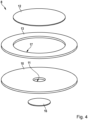
- the embodiment according to Figure 4 shows an internal valve 8 with a round contour.
- the base film 10 is circular and has an opening 11 in the middle.
- the opening 11 is circular, for example.
- the frame film 13 is made in one piece.
- the frame film 13 completely surrounds the membrane 12. As a result, no channels are formed on the sides.
- the other side of the opening 11, which faces away from the membrane 12, is covered by the filter 16, in particular a filter fleece 16.
- the filter 16 or the fleece is required to prevent particles of the filling material from penetrating the valve 8 between the membrane 12 and the base film 10, which would impair the function.
- the filter 16 is circular.
- the frame film 13 has a circular inner diameter and a circular outer diameter with a constant width. A circular free area 17 is formed accordingly.
- the membrane 12 is in turn circular.
- the diameter of the membrane 12 is smaller than the diameter of the free area 17.
- the membrane 12 lies loosely on the base film 10, held in place by the fluid.
- the fluid lies between the membrane 12 and the base film 10.
- the free upper side of the frame film 13 is connected to the inside of the packaging.
- the packaging has a small opening in the area of the membrane 12 or opening 11 to relieve the excess pressure.
- the frame foil 13 according to Figure 5 is characterized by only one opening in the frame film 13, so that a single channel 18 is formed.
- the free area 17 is again circular with a slightly larger diameter than that of the membrane 12.
- the frame film 13 is preferably formed in one piece.
- the connection of the base film 10 to the frame film 13 and/or the frame film 13 to the cover film 15 is preferably carried out by a welding process.
- the films 10, 13, 15 are designed to be weldable.
- the films 10, 13, 15 are preferably made of plastic.
- the valve 8 is particularly preferably made of films of the same material. Polypropylene is particularly suitable here.
- the uniform material of the various films 10, 13, 15 makes reusability easier. Plastics made from renewable raw materials or biodegradable plastics can also be used.
- the base film 10 and/or the frame film 13 and/or the cover film 15 can, for example, be made of polypropylene, preferably OPP (oriented polypropylene), a longitudinally stretched or biaxially stretched polypropylene.
- the base film 10 and/or the frame film 13 and/or the cover film 15 and/or the membrane 12 can alternatively be made of PET. Multilayer films are also conceivable, such as PP-EVOH-PP.
- the material for the membrane 12 is characterized by a high oxygen barrier.
- the membrane 12 is made of PET.
- the edge lengths of the base film 10 can be in the range between preferably 12.5 and 20 mm.
- the thickness of the base film 10 is preferably in the range of 0.1 mm and 0.25 mm, particularly preferably 0.125 mm, for example.
- the fluid for example silicone oil, based on bio-based materials or renewable raw materials, for example based on palm oil, coconut oil or the like, is applied as a fluid film.
- the volume of the fluid film is approx. 2-5 ⁇ l.
- the thickness of the membrane 12 is, for example, in a range between 0.025 mm and 0.075 mm, preferably 0.05 mm.
- the thickness of the frame film 13 is, for example, in the range between 0.1 mm and 0.2 mm.
- the thickness of the frame foil 13 is greater than the thickness of the membrane 12.
- the thickness of a possible cover foil 15 is, for example, in the range of 0.05 mm to 0.15 mm, particularly preferably 0.1 mm. Depending on the application, Thicknesses can vary depending on material selection, joining methods, etc.
- valves 8 described are used, for example, as aroma protection valves in packaging of outgassing products such as coffee beans, ground coffee, fresh dough or similar, where excess pressure develops in the packaging. Pressure is reduced by lifting the membrane 12 relative to the opening 11 and then escaping via the free area 17 or - in the case of an external valve - via at least one lateral channel 18 connected to the free area 17, which is formed between the frame film 13 and the cover film 15.
Landscapes
- Engineering & Computer Science (AREA)
- Mechanical Engineering (AREA)
- Packages (AREA)
- Bag Frames (AREA)
- Lining Or Joining Of Plastics Or The Like (AREA)
Description
- Die vorliegende Erfindung betrifft ein Ventil, insbesondere ein Überdruckventil für einen Verpackungsbehälter, nach der Gattung des unabhängigen Anspruchs.
- Derartige Ventile kommen in der Verpackungstechnik zum Einsatz, wenn das Füllgut zum Ausgasen neigt wie beispielsweise bei frisch geröstetem Kaffee.
- So ist beispielsweise aus der
EP 760790 B1 EP 2396244 B1 ist ein gattungsgemäßes Überdruckventil bekannt, welches einen Grundkörper mit einer zweistufig ausgebildeten Vertiefung und eine Membran umfasst, wobei die Membran eine zu einer Dichtfläche gerichtete, verformbare Oberfläche aufweist. Der Grundkörper ist relativ komplex aufgebaut. - Des Weiteren sind aus
EP 1 538 107 A2 ,US 6 662 827 B1 undUS 2012/243807 A1 Ventile für einen Verpackungsbehälter bekannt, die ein Grundelement mit einer Öffnung sowie zumindest ein Rahmenelement umfassen, das einen freien Bereich umgibt, wobei das Rahmenelement mit dem Grundelement verbunden ist, wobei zumindest eine Membran vorgesehen ist, die auf dem Grundelement angeordnet ist und die Öffnung überdeckt, wobei zwischen der Membran und dem Grundelement ein Fluid vorgesehen ist, wobei die Membran innerhalb des freien Bereichs auf dem Grundelement beweglich angeordnet ist. - Das erfindungsgemäße Ventil für einen Verpackungsbehälter hat demgegenüber den Vorteil, dass das Ventil einfacher produziert werden kann. Zudem verbessert sich die Funktion des Ventils. Außerdem zeichnet sich das Ventil durch reduzierte Herstellkosten aus. Der grundsätzliche Aufbau des Ventils kann sowohl außerhalb des Verpackungsbehälters wie auch in einer bestimmten Ausführungsvariante innerhalb am Verpackungsbehälter appliziert werden. Dies wird erfindungsgemäß dadurch möglich, dass die Membran auf einer Grundfolie zumindest teilweise schwimmend bzw. frei beweglich innerhalb des freien Bereichs angeordnet ist. Die Membran ist somit nicht mehr großflächig am Grundkörper verbunden und wird somit deutlich weniger von äußeren Einflüssen beeinträchtigt wie beispielsweise Verzug. Durch den vorgeschlagenen Aufbau von Grundfolie, Rahmenfolie und gegebenenfalls Deckfolie (quasi eine Art Doppel-T-Träger) ergibt sich eine hohe Biegesteifigkeit bei vergleichsweise geringem Materialeinsatz. Das Ventil kombiniert die guten Ventileigenschaften eines spritzgegossenen Ventils mit denen eines Folienventils. Es bietet sehr geringe Öffnungs- und Schließdrücke. Aufgebaut wird das Ventil aus mehreren Folienschichten, die beispielsweise auf Rotationsstanzwerkzeugen hergestellt und anschließend aufeinander laminiert werden. Das Fügen erfolgt idealerweise durch eine Schweißverbindung. Alternativ könnte auch ein Haftvermittler wie Klebstoff eingesetzt werden. Das vorgeschlagene Ventil kann bevorzugt aus einer einzelnen Materialsorte hergestellt werden und ist damit leichter rezyklierbar und somit umweltverträglicher bzw. besser schweißbar. In einer zweckmäßigen Weiterbildung besteht die Folie aus Polypropylen. Jedoch auch erneuerbare Materialien wie beispielsweise Kunststoffe aus nachwachsenden Rohstoffen oder biologisch abbaubare Kunststoffe wären möglich.
- In einer zweckmäßigen Weiterbildung ist die Rahmenfolie so ausgebildet, dass diese die Membran umgibt, sodass die Membran den freien Bereich nicht verlassen kann.
- Erfindungsgemäß weist die Rahmenfolie zumindest eine Unterbrechung auf, sodass sich zunächst ein Kanal ausbildet. Über diesen Kanal kann sich der eventuell entstehende Überdruck abbauen. Beim Vorsehen genau einer Unterbrechung wird sichergestellt, dass die Rahmenfolie bevorzugt einteilig ausgebildet sein kann. Dies erleichtert das Handling und das Aufbringen der Rahmenfolie.
- Besonders zweckmäßig ist der freie Bereich kreisförmig ausgebildet mit einem Radius, der größer ist als ein Radius der kreisförmig ausgebildeten Membran. Diese Anordnung lässt sich besonders einfach fertigen und stellt zudem eine hinreichend freie Beweglichkeit der Membran sicher. Besonders bevorzugt ist die Dicke der Rahmenfolie größer als die Dicke der Membran, sodass zuverlässig ein Abheben der Membran von der Öffnung erreicht werden kann.
- In einer zweckmäßigen Weiterbildung ist die Dicke der Rahmenfolie größer als die Dicke der Membran, vorzugsweise 75 % bis 225 % größer. Dadurch wird ein besonders sicheres Abheben der Membran möglich.
- In einer zweckmäßigen Weiterbildung ist zumindest eine Deckfolie vorgesehen, die mit der Rahmenfolie verbunden ist. Gerade bei einem außenliegenden Ventil wird so die Membran vor Umwelteinflüssen geschützt und sichergestellt, dass die Membran nicht vollständig abheben und vom Grundkörper getrennt werden kann bzw. verloren geht.
- In einer zweckmäßigen Weiterbildung besteht die Grundfolie und/oder die Rahmenfolie und/oder die Deckfolie aus Polypropylen, OPP, PET, Polyolefin oder aus Kunststoff, vorzugsweise aus nachwachsenden Rohstoffen oder biologisch abbaubaren Kunststoffen. Dadurch kann die Wiederverwertbarkeit bzw. Umweltverträglichkeit erhöht werden.
- In einer zweckmäßigen Weiterbildung werden Rahmenfolie und/oder Grundfolie und/oder Deckfolie über eine Schweißverbindung verbunden, insbesondere laminiert. Dadurch kann im Herstellprozess aufgrund erhöhter Reinigungsanforderungen auf unerwünschten Klebstoff verzichtet werden, der zudem teuer ist. Bei einem innenliegenden Ventil wird so vermieden, dass sich Klebstoff auf der dem Produkt zugewandten Seite befindet.
- In einer zweckmäßigen Weiterbildung ist vorgesehen, dass die Grundfolie eine Dicke zwischen 0,1 mm und 0,25 mm, insbesondere 0,125 mm, aufweist und/oder die Rahmenfolie eine Dicke zwischen 0,1 mm und 0,2 mm aufweist und/oder die Deckfolie eine Dicke zwischen 0,05 mm und 0,15 mm, insbesondere 0,1 mm, aufweist und/oder die Membran eine Dicke zwischen 0,025 mm bis 0,075 mm, insbesondere 0,05 mm, aufweist. Gerade solche Foliendicken eignen sich zum einen für eine gute Herstellbarkeit und eignen sich in Verbindung mit weiteren Geometrie zur Einstellung bevorzugter Öffnungsdrücke für dieses Anwendungsfeld.
- Gemäß den beschriebenen Schritten des Herstellverfahrens kann besonders zweckmäßig auf lediglich eine Folie zurückgegriffen werden, die als Basismaterial für die Grundfolie und/oder die Rahmenfolie und/oder die Deckfolie verwendet wird. Gerade durch das Falten und Verbinden können ansonsten aufwendige Füge- bzw. Zuführprozesse entfallen. Sowohl die Herstellung der Öffnung wie auch die Herstellung des freien Bereichs kann in ein und demselben Schritt mit nur einem Stanzwerkzeug vorgenommen werden. Dies vereinfacht die Herstellung weiter. Durch das Einbringen der Membran in einem Zustand, in dem die Ventile noch nicht voneinander getrennt wurden, kann eine hohe Positionsgenauigkeit erreicht werden.
- Weitere zweckmäßige Weiterbildungen ergeben sich aus weiteren abhängigen Ansprüchen und aus der Beschreibung.
- Unter Bezugnahme auf die beigefügten Figuren werden Ausführungsformen der Erfindung im Detail beschrieben. Es zeigen:
- Figur 1
- den Ventilaufbau eines ersten Ausführungsbeispiels für ein außenliegendes Ventil,
- Figur 2
- ein weiteres Ausführungsbeispiel eines außenliegenden Ventils mit runder Geometrie,
- Figur 3
- ein weiteres Ausführungsbeispiel eines innenliegenden Ventils mit rechteckförmiger bzw. quadratischer Geometrie und mit einer geschlossenen Rahmenfolie (nicht vom Anspruch 1 umfasst),
- Figur 4
- ein weiteres Ausführungsbeispiel eines innenliegenden Ventils mit runder Geometrie und mit einer geschlossenen Rahmenfolie (nicht vom Anspruch 1 umfasst),
- Figur 5
- ein weiteres alternatives Ausführungsbeispiel einer Rahmenfolie. Bevorzugte Ausführungsformen der Erfindung Nachfolgend werden unter Bezugnahme auf die Figuren die Ausführungsbeispiele der Erfindung im Detail beschrieben, wobei in den anhand der
Figuren 3 und4 dargelegten Beispielen das Erfingdungsmerkmal "die Rahmenfolie weist mindestens eine Unterbrechung auf, sodass sich zumindest ein Kanal ausbildet" fehlt. -
Figur 1 zeigt die einzelnen Komponenten eines Ventils 8 gemäß einem ersten Ausführungsbeispiel. Das Ventil 8 umfasst eine Grundfolie 10. Die Grundfolie 10 ist mit einer Öffnung 11 versehen. Beispielhaft weist die Öffnung 11 die Geometrie von zwei sich schneidenden Kreisen auf. Beliebige andere Geometrien sind jedoch denkbar. Besonders bevorzugt ist die Geometrie auf die gewünschten Öffnungs- und Schließdrücke abzustimmen. Weiterhin ist zumindest eine Rahmenfolie 13 vorgesehen. Die Rahmenfolie 13 ist so ausgebildet, dass eine Membran 12 zumindest teilweise, jedoch verliersicher, umgeben ist. Hierzu weist die Rahmenfolie 13 einen freien Bereich 17 auf, in dem die Membran 12 angeordnet wird. Die Membran 12 kommt im montierten Zustand zwischen den im Ausführungsbeispiel zwei Teilen der Rahmenfolie 13 zu liegen. Bei dem gezeigten außenliegenden Ventil 8 ist außerdem eine Deckfolie 15 ist vorgesehen. Im montierten Zustand befindet sich zwischen der Grundfolie 10 und der Membran 12 ein Fluid bzw. Fluidfilm, beispielsweise Silikonöl, auch biologische Fluide wie Palmöl, Kokosöl oder dergleichen. Die Membran 12 ist ebenfalls als Folie ausgebildet. Die Membran 12 überdeckt die Öffnung 11. Zum Entweichen eines Überdrucks aus der Verpackung kann die Membran 12 von der Öffnung 11 abheben, sodass sich Überdruck in der Verpackung nach außen hin abbauen kann. - Das Ausführungsbeispiel gemäß
Figur 1 weist eine rechteckförmige, vorzugsweise quadratische Grundform auf. So sind die Grundfolie 10 sowie die Deckfolie 15 rechteckförmig, insbesondere quadratisch ausgebildet. Die Außenseiten der Rahmenfolie 13 fluchten mit der jeweils darunter bzw. darüber angeordneten Grundfolie 10 bzw. Deckfolie 15. Die Membran 12 ist kreisförmig ausgeführt und zentrisch zur Öffnung 11 angeordnet. Die Innenseiten der Rahmenfolie 15 ist zumindest teilweise teilkreisförmig ausgebildet, sodass sich ein konstanter Abstand zur Membran 12 einstellt. Dadurch bildet sich der kreisförmige freie Bereich 17. Die Rahmenfolie 15 umschließt die Membran 12 von zumindest zwei Seiten. Somit bilden sich zwei Kanäle 18 aus, über die der Überdruck entweichen kann. Die Breite des Kanals 18 ist kleiner als der Durchmesser der Membran 12. Damit wird sichergestellt, dass die Membran 12 innerhalb der Rahmenfolie 13 verbleibt. Auch andere Geometrien der Rahmenfolie 15 sind denkbar. Besonders bevorzugt sind es solche Geometrien der Rahmenfolie 15 mit nur einem Kanal 18, da hierbei die Rahmenfolie 15 einteilig ausgebildet ist. Dies ist beispielhaft inFigur 5 gezeigt, wobei ein freier Bereich 17 der Rahmenfolie 15 auf einer Seite hin über nur einen Kanal 18 geöffnet ist. Der Kanal 18 verläuft dabei parallel zu den Seitenflächen. Wesentlich ist die Ausbildung der Rahmenfolie 15 dergestalt, dass die zwischen Grundfolie 10 und Deckfolie 15 (bzw. Verpackungswand bei einem innenliegenden Ventil 8) angeordnete Membran 12 diesen Bereich nicht verlassen kann. Hierzu verbleibt die Membran 12 in dem freien Bereich 17. - Das Ventil 8 ist aus mehreren Folienschichten aufgebaut Im Ausführungsbeispiel gemäß
Figur 1 sind dies die Grundfolie 10, die Membran 12, die Rahmenfolie 13 sowie (optional für außenliegende Ventile 8) die Deckfolie 15. Zum Herstellen des montierten Ventils 8 werden die Folienschichten, die beispielsweise auf Stanzwerkzeugen, insbesondere Rotationsstanzwerkzeugen, hergestellt und anschließend laminiert. Das Fügen der Folienschichten erfolgt bevorzugt durch eine Schweißverbindung. Durch geeignete Schweißverfahren wird der für die entsprechenden Foliendicken geeignete Wärmeeintrag eingebracht, so dass sich eine feste Verbindung der verschiedenen Folienschichten (Grundfolie 10, Rahmenfolie 13, optional Deckfolie 15) ergibt. Hilfsweise kann das Fügen durch einen Haftvermittler (Klebstoff) erfolgen - Die Membran 12 liegt lose auf der Grundfolie 10. Die Membran 12 ist schwimmend mit der Grundfolie 10 über ein nicht gezeigtes, zwischen Grundfolie 10 und Membran angeordnetem, Fluid verbunden. Das Fluid bewirkt, dass sich die Membran 12 durch Kapilarkräfte dicht an die Grundfolie 10 anlegt und die Öffnung 11 gasdicht verschließt, jedoch bei Überdruck abheben kann. Die Dichtfläche ist somit der Fluidfilm zwischen Membran 12 und Grundfolie 10. Hierzu wird die Membran 12 in den freien Bereich 17, umgeben durch die Rahmenfolie 13, eingebracht. Die Deckfolie 15, die bei einem außenliegenden Ventil 8 zum Einsatz kommt, schützt die Membran 12 vor äußeren Einflüssen und verhindert ein vollständiges Abheben der Membran 12. Die Rahmenfolie 13 umgibt die Membran 12. Die Rahmenfolie 13 stellt die Lage der Membran 12 sicher.
- In
Figur 2 ist ein weiteres Ausführungsbeispiel des Ventils 8 gezeigt. Es zeichnet sich durch eine kreisförmige Geometrie aus. Die kreisförmige Grundfolie 10 weist eine mittig angeordnete Öffnung 11 auf. Die Öffnung 11 ist kreisförmig ausgebildet. Die Rahmenfolie 13 besteht aus vier Teilfolien. Die Teilfolien der Rahmenfolie 13 sind jeweils identisch ausgebildet und schließen randseitig bündig mit der Außenkontur der Grundfolie 10 ab. Die Rahmenfolie 13 umschließt den freien Bereich 17, in dem die Membran 12 angeordnet wird. Die Breite der Teilfolien der Rahmenfolie 13 ist konstant, so dass auch der zur Membran 12 orientierte Rand kreisförmig verläuft. Die Teilfolien der Rahmenfolie 13 umgeben die Membran 12. Die Membran 12 ist kreisförmig ausgebildet. Durch die vier Teilfolien bilden sich jeweils zwischen zwei aneinandergrenzenden Teilfolien in Summe vier Kanäle 18. Das Ventil 8 ist als außenliegendes Ventil ausgebildet, wird also an der Außenseite der Verpackung angebracht. Zum Schutz der Membran 12 ist wiederum die Deckfolie 15 vorgesehen. Die Deckfolie 15 ist kreisförmig ausgebildet und wird mit der Rahmenfolie 13 verbunden. Sie entspricht der Kontur der Grundfolie 10. Im montierten Zustand fluchten die Außenkanten von Grundfolie 10, Rahmenfolie 13 und Deckfolie 15. Im montierten Zustand ist zwischen der Grundfolie 10 und der Membran 12 ein Fluidfilm vorgesehen. Wiederum liegt die dünne Membran 12 lose auf der Grundfolie 10 in dem freien Bereich 17. Dazwischen befindet sich das Fluid. Zwischen dem freien Bereich 17 im Inneren des Ventils 8 stellen die vier Kanäle 18 eine Verbindung zur Umgebung her. - Das Ausführungsbeispiel gemäß
Figur 3 zeigt ein innenliegendes Ventil 8, das Ventil 8 wird also an der Innenseite der Verpackung angeordnet. Das Ventil 8 besteht wiederum aus einer Grundfolie 10. Die Grundfolie 10 weist zumindest eine Öffnung 11 auf. Auf der Grundfolie 10 ist die Rahmenfolie 13 angeordnet. Die Rahmenfolie 13 weist einen geschlossenen, die Membran 12 vollständig umgebenden Rand auf. Der so begrenzte Bereich ist der kreisförmige freie Bereich 17. Damit bilden sich seitlich keine Kanäle 18 aus. Die Membran 12 ist lose auf der Grundfolie 10 angeordnet, und zwar in dem freien Bereich 17. Zwischen der Membran 12 und der Grundfolie 10 ist ein Fluidfilm vorgesehen. Im montierten Zustand des Ventils 8 wird die Oberseite der Rahmenfolie 13 mit der Innenseite der Verpackung verbunden. Im Bereich der Membran 12 weist die Verpackung eine kleine Öffnung auf, sodass hierüber nach kurzem Abheben der Membran 12 der Überdruck entweichen kann. Die andere Seite der Öffnung 11 wird durch ein Filter 16, insbesondere ein Filtervlies 16, überdeckt. Der Filter 16 bzw. das Vlies wird benötigt, um zu verhindern, dass Partikel des Füllguts in das Ventil 8 zwischen Membran 12 und Grundfolie 10 eindringen können, wodurch die Funktion beeinträchtigt würde. Im Ausführungsbeispiel ist der Filter 16 kreisförmig ausgebildet. Das Ausführungsbeispiel gemäßFigur 3 zeichnet sich durch eine rechteckförmige, insbesondere quadratische Grundform der Grundfolie 10 und Rahmenfolie 13 aus. Die Membran 12 ist kreisförmig ausgebildet. Auch die innere Kontur der Rahmenfolie 13, der freie Bereich 17, ist kreisförmig ausgebildet, entsprechend der Außengeometrie der Membran 12, mit einem leicht größeren Durchmesser als die Membran 12. Die Öffnung 11 besitzt beispielhaft die Kontur von zwei sich schneidenden Kreisen. - Das Ausführungsbeispiel gemäß
Figur 4 zeigt ein innenliegendes Ventil 8 mit einer runden Kontur. Die Grundfolie 10 ist kreisförmig ausgebildet und weist in der Mitte eine Öffnung 11 auf. Die Öffnung 11 ist beispielhaft kreisförmig ausgebildet. Die Rahmenfolie 13 ist einteilig ausgebildet. Die Rahmenfolie 13 umgibt vollständig die Membran 12. Dadurch bilden sich seitlich keine Kanäle aus. Die andere Seite der Öffnung 11, die der Membran 12 abgewandt ist, wird durch den Filter 16, insbesondere ein Filtervlies 16, überdeckt. Der Filter 16 bzw. das Vlies wird benötigt, um zu verhindern, dass Partikel des Füllguts in das Ventil 8 zwischen Membran 12 und Grundfolie 10 eindringen können, wodurch die Funktion beeinträchtigt würde. Im Ausführungsbeispiel ist der Filter 16 kreisförmig ausgebildet. Die Rahmenfolie 13 weist einen kreisförmigen Innendurchmesser sowie einen kreisförmigen Außendurchmesser auf mit konstanter Breite. Entsprechend bildet sich ein kreisförmiger freier Bereich 17 aus. Die Membran 12 ist wiederum kreisförmig ausgebildet. Der Durchmesser der Membran 12 ist kleiner als der Durchmesser des freien Bereichs 17. Die Membran 12 liegt im montierten Zustand lose auf der Grundfolie 10, dichtend gehalten wiederum durch das Fluid. Zwischen Membran 12 und Grundfolie 10 liegt das Fluid. Die freie Oberseite der Rahmenfolie 13 wird mit der Innenseite der Verpackung verbunden. Die Verpackung weist im Bereich der Membran 12 bzw. Öffnung 11 zum Abbau des Überdrucks eine kleine Öffnung auf. - Die Rahmenfolie 13 gemäß
Figur 5 zeichnet sich durch lediglich eine Öffnung in der Rahmenfolie 13 aus, sodass sich ein einziger Kanal 18 bildet. Der freie Bereich 17 ist wiederum kreisförmig ausgebildet mit leicht größeren Durchmesser als derjenige der Membran 12. Die Rahmenfolie 13 ist vorzugsweise einteilig ausgebildet. - Die Verbindung der Grundfolie 10 mit der Rahmenfolie 13 und/oder der Rahmenfolie 13 mit der Deckfolie 15 erfolgt bevorzugt durch ein Schweißverfahren. Die Folien 10, 13, 15 sind schweißbar ausgebildet. Die Folien 10, 13, 15 bestehen bevorzugt aus Kunststoff. Besonders bevorzugt besteht das Ventil 8 aus Folien mit demselben Material. Besonders eignet sich hierbei Polypropylen. Aufgrund des einheitlichen Materials der verschiedenen Folien 10,13, 15 vereinfacht sich die Wiederverwendbarkeit. Auch Kunststoffe aus nachwachsenden Rohstoffen oder biologisch abbaubare Kunststoffe können zum Einsatz kommen. Grundfolie 10 und/oder Rahmenfolie 13 und/oder Deckfolie 15 können beispielsweise aus Polypropylen bestehen, bevorzugt aus OPP (oriented polypropylene), einem längsverstreckten oder biaxial verstreckten Polypropylen. Grundfolie 10 und/oder Rahmenfolie 13 und/oder Deckfolie 15 und/oder Membran 12 können alternativ aus PET bestehen. Auch Multilayerfolien sind ebenfalls denkbar wie beispielsweise PP-EVOH-PP. Das Material für die Membran 12 zeichnet sich durch eine hohe Sauerstoffbarriere aus. Beispielsweise besteht die Membran 12 aus PET.
- Nachfolgende Geometrien könnten sich für die Ventile 8 besonders eignen. Bei den Ausführungsbeispielen gemäß
Figur 1 bzw. 3 (quadratische Grundform) können die Kantenlängen der Grundfolie 10 im Bereich zwischen bevorzugt 12,5 und 20 mm liegen. Die Dicke der Grundfolie 10 bewegt sich bevorzugt im Bereich von 0,1 mm und 0,25 mm, besonders bevorzugt beispielsweise 0,125 mm. Das Fluid, beispielsweise Silikonöl, auf Basis von bio-basierten Materialien bzw. nachwachsenden Rohstoffen, beispielsweise auf Basis von Palmöl, Kokosöl oder Ähnliches, wird als Fluidfilm aufgetragen. Das Volumen des Fluidfilms beträgt ca. 2-5 µl. Die Dicke der Membran 12 liegt beispielsweise in einem Bereich zwischen 0,025 mm bis 0,075 mm, bevorzugt bei 0,05 mm. Die Dicke der Rahmenfolie 13 liegt beispielsweise im Bereich zwischen 0,1 mm und 0,2 mm. Die Dicke der Rahmenfolie 13 ist größer als die Dicke der Membran 12. Die Dicke einer möglichen Deckfolie 15 liegt beispielsweise im Bereich von 0,05 mm bis 0,15 mm, besonders bevorzugt bei 0,1 mm. Je nach Anwendungsfälle, Materialauswahl, Verbindungsverfahren etc. können die Dicken entsprechend variieren. - Die beschriebenen Ventile 8 werden beispielsweise als Aromaschutzventile bei Verpackungen von ausgasenden Produkten wie beispielsweise Kaffeebohnen, Mahlkaffee, Frischteig oder Ähnliches verwendet, bei denen ein Überdruck in der Verpackung entsteht. Ein Druckabbau erfolgt durch ein Anheben der Membran 12 relativ zu der Öffnung 11 und anschließendes Entweichen über den freien Bereich 17 bzw. - im Falle von einem außenliegenden Ventil - über zumindest einen mit dem freien Bereich 17 in Verbindung stehenden seitlichen Kanal 18, der zwischen Rahmenfolie 13 und Deckfolie 15 ausgebildet ist.
Claims (14)
- Ventil für einen Verpackungsbehälter, umfassend zumindest eine Grundfolie (10) mit einer Öffnung (11), zumindest eine Rahmenfolie (13), die einen freien Bereich (17) umgibt, wobei die Rahmenfolie (13) mit der Grundfolie (10) verbunden ist, wobei zumindest eine Membran (12) vorgesehen ist, die auf der Grundfolie (10) angeordnet ist und die Öffnung (11) überdeckt, wobei zwischen der Membran (12) und der Grundfolie (10) ein Fluid vorgesehen ist, wobei die Membran (12) innerhalb des freien Bereichs (17) auf der Grundfolie (10) beweglich angeordnet ist, dadurch gekennzeichnet, dass die Rahmenfolie (13) mindestens eine Unterbrechung aufweist, sodass sich zumindest ein Kanal (18) ausbildet.
- Ventil nach Anspruch 1, dadurch gekennzeichnet, dass die Rahmenfolie (13) so ausgebildet ist, die Membran (12) zu umgeben, so dass die Membran (12) den freien Bereich (17) nicht verlassen kann.
- Ventil nach einem der vorhergehenden Ansprüche, dadurch gekennzeichnet, dass die Rahmenfolie (13) einteilig ausgebildet ist.
- Ventil nach einem der vorhergehenden Ansprüche, dadurch gekennzeichnet, dass der freie Bereich (17) kreisförmig ausgebildet ist mit einem Radius, welcher größer ist als ein Radius der kreisförmig ausgebildeten Membran (12).
- Ventil nach einem der vorhergehenden Ansprüche, dadurch gekennzeichnet, dass die Dicke der Rahmenfolie (13) größer ist als die Dicke der Membran (12), vorzugsweise um 75% bis 225 % größer.
- Ventil nach einem der vorhergehenden Ansprüche, dadurch gekennzeichnet, dass die Grundfolie (10), die Rahmenfolie (13) und die Membran (12) innerhalb eines Verpackungsbehälters oder außerhalb eines Verpackungsbehälters gleichermaßen verwendbar bzw. anordenbar sind.
- Ventil nach einem der vorhergehenden Ansprüche, dadurch gekennzeichnet, dass zumindest eine Deckfolie (15) vorgesehen ist, die mit der Rahmenfolie (13) verbunden ist.
- Ventil nach einem der vorhergehenden Ansprüche, dadurch gekennzeichnet, dass zumindest ein Filter (16), insbesondere Filtervlies, vorgesehen ist, zur Überdeckung der Öffnung (11).
- Ventil nach einem der vorhergehenden Ansprüche, dadurch gekennzeichnet, dass Grundfolie (10) und/oder Rahmenfolie (13) und/oder Deckfolie (15) aus Polypropylen, OPP, PET, Polyolefin oder aus Kunststoff, vorzugsweise aus nachwachsenden Rohstoffen oder biologisch abbaubaren Kunststoffen, besteht.
- Ventil nach einem der vorhergehenden Ansprüche, dadurch gekennzeichnet, dass die Rahmenfolie (13) mit der Grundfolie (10) und/oder der Deckfolie (15) über eine Schweißverbindung verbunden ist, insbesondere laminiert ist.
- Ventil nach einem der vorhergehenden Ansprüche, dadurch gekennzeichnet, dass die Grundfolie (10) eine Dicke zwischen 0,1 mm und 0,25 mm, insbesondere 0,125 mm, aufweist und/oder die Rahmenfolie (13) eine Dicke zwischen 0,1 mm und 0,2 mm aufweist und/oder die Deckfolie (15) eine Dicke zwischen 0,05 mm und 0,15 mm, insbesondere 0,1 mm, aufweist und/oder die Membran (12) eine Dicke zwischen 0,025 mm bis 0,075 mm, insbesondere 0,05 mm, aufweist.
- Ventil nach einem der vorhergehenden Ansprüche, dadurch gekennzeichnet, dass die Membran (12) auf der Grundfolie (10) zumindest teilweise schwimmend bzw. frei beweglich innerhalb des freien Bereichs (17) angeordnet ist.
- Ventil nach einem der vorhergehenden Ansprüche, dadurch gekennzeichnet, dass die Rahmenfolie (13) die Membran (12) von zumindest zwei Seiten umschließt, wobei sich zumindest zwei Kanäle (18) ausbilden, über die ein Überdruck entweichen kann, wobei eine Breite des jeweiligen Kanals (18) kleiner ist als der Durchmesser der Membran (12).
- Ventil nach Anspruch 8, dadurch gekennzeichnet, dass eine andere Seite der Öffnung (11), die der Membran (12) abgewandt ist, durch den Filter (16) überdeckt ist.
Applications Claiming Priority (2)
| Application Number | Priority Date | Filing Date | Title |
|---|---|---|---|
| DE102019214315.6A DE102019214315A1 (de) | 2019-09-19 | 2019-09-19 | Ventil für einen Verpackungsbehälter |
| PCT/EP2020/076114 WO2021053149A1 (de) | 2019-09-19 | 2020-09-18 | Ventil für einen verpackungsbehälter |
Publications (2)
| Publication Number | Publication Date |
|---|---|
| EP4031459A1 EP4031459A1 (de) | 2022-07-27 |
| EP4031459B1 true EP4031459B1 (de) | 2024-08-07 |
Family
ID=72613909
Family Applications (1)
| Application Number | Title | Priority Date | Filing Date |
|---|---|---|---|
| EP20775845.9A Active EP4031459B1 (de) | 2019-09-19 | 2020-09-18 | Ventil für einen verpackungsbehälter |
Country Status (5)
| Country | Link |
|---|---|
| US (1) | US12252322B2 (de) |
| EP (1) | EP4031459B1 (de) |
| JP (1) | JP7463497B2 (de) |
| DE (1) | DE102019214315A1 (de) |
| WO (1) | WO2021053149A1 (de) |
Family Cites Families (15)
| Publication number | Priority date | Publication date | Assignee | Title |
|---|---|---|---|---|
| DE2625350C2 (de) * | 1976-06-04 | 1982-11-11 | Hag Ag, 2800 Bremen | Überdruckventil für Verpackungsbehälter |
| JP2754751B2 (ja) * | 1989-06-20 | 1998-05-20 | 藤森工業株式会社 | ガス抜き用弁 |
| DE19510489A1 (de) * | 1995-03-27 | 1996-10-02 | Bosch Gmbh Robert | Überdruckventil für einen Verpackungsbehälter |
| US6662827B1 (en) | 2002-07-15 | 2003-12-16 | Sonoco Development, Inc. | Overpressure relief valve for packaging container |
| ITMI20032238A1 (it) * | 2003-11-18 | 2005-05-19 | P L V Spa | Valvola di degasazione unidirezionale per contenitori ermetici di prodotti che degasano. |
| DE102004062026A1 (de) | 2004-09-29 | 2006-03-30 | Robert Bosch Gmbh | Überdruckventil für einen Verpackungsbehälter |
| DE102004061262A1 (de) * | 2004-12-20 | 2006-06-29 | Robert Bosch Gmbh | Überdruckventil für einen Verpackungsbehälter |
| DE102006016594A1 (de) * | 2006-04-06 | 2007-10-18 | Tesa Ag | Überdruckventil für einen Verpackungsbehälter |
| US8038023B2 (en) * | 2008-05-21 | 2011-10-18 | Sonoco Development, Inc. | Molded container with degassing valve |
| DE102009000802A1 (de) * | 2009-02-12 | 2010-08-19 | Robert Bosch Gmbh | Überdruckventil für einen Verpackungsbehälter |
| US20120243807A1 (en) | 2011-03-25 | 2012-09-27 | Pascoe Gregory A | Gas exhaust valve for packages |
| US8636034B2 (en) | 2011-08-31 | 2014-01-28 | Plitek, L.L.C. | Oil-less and wetted pressure relief valves having an integrated filter |
| EP2719637B1 (de) | 2012-10-09 | 2016-08-24 | Plitek, LLC | Ölfreies und benetzte druckbegrenzungsventile mit integriertem filter |
| DE102014105193A1 (de) * | 2014-04-11 | 2015-10-15 | Schreiner Group Gmbh & Co. Kg | Druckausgleichsetikett zum Aufkleben auf eine Oberfläche und Verfahren |
| DE102019200860A1 (de) | 2019-01-24 | 2020-07-30 | Syntegon Technology Gmbh | Überdruckventil mit schwimmender Membran |
-
2019
- 2019-09-19 DE DE102019214315.6A patent/DE102019214315A1/de active Pending
-
2020
- 2020-09-18 EP EP20775845.9A patent/EP4031459B1/de active Active
- 2020-09-18 JP JP2022517304A patent/JP7463497B2/ja active Active
- 2020-09-18 US US17/640,070 patent/US12252322B2/en active Active
- 2020-09-18 WO PCT/EP2020/076114 patent/WO2021053149A1/de not_active Ceased
Also Published As
| Publication number | Publication date |
|---|---|
| WO2021053149A1 (de) | 2021-03-25 |
| US20220332489A1 (en) | 2022-10-20 |
| DE102019214315A1 (de) | 2021-03-25 |
| EP4031459A1 (de) | 2022-07-27 |
| JP2022550277A (ja) | 2022-12-01 |
| JP7463497B2 (ja) | 2024-04-08 |
| US12252322B2 (en) | 2025-03-18 |
Similar Documents
| Publication | Publication Date | Title |
|---|---|---|
| DE3935201C2 (de) | ||
| DE2505492C2 (de) | ||
| EP3010838B2 (de) | Kapsel mit einem kapselkörper und verfahren zu dessen herstellung | |
| EP3393661B1 (de) | Mikrofluidische vorrichtung und verfahren zum betreiben einer mikrofluidischen vorrichtung | |
| DE102007035728B4 (de) | Vorrichtung zum Öffnen und Verschließen eines Getränkebehälters | |
| DE2108061C3 (de) | Behälter mit einem Hals, der durch einen dem Hals bei seiner Formung einstückig angeformten durchstoßbaren Deckel verschlossen ist, und Verfahren zu seiner Herstellung | |
| EP2808082A1 (de) | Vorrichtung mit Membrane zur vorgegebener Fluidverdrängung | |
| EP1421012B1 (de) | Überdruckventil für einen verpackungsbehälter und vorrichtung zum anbringen des überdruckventils an einer materialbahn | |
| DE102004026538A1 (de) | Mit einem Schüttgut befüllbarer Sack aus Kunststofffolie | |
| EP4031460B1 (de) | Ventil für einen verpackungsbehälter | |
| EP4031459A1 (de) | Ventil für einen verpackungsbehälter | |
| WO2022122718A2 (de) | Portionskapsel zur zubereitung eines getränks in einer getränkeherstellungsmaschine und verfahren zur herstellung einer portionskapsel | |
| DE102019214316A1 (de) | Verfahren zur Herstellung eines Ventils, insbesondere eines Überdruckventils für einen Verpackungsbehälter | |
| EP3325349B1 (de) | Verfahren und werkzeug zum dichten verschliessen eines behaelters sowie dichtend verschlossener behaelter | |
| WO2022122512A1 (de) | Verfahren zum herstellen eines kissens und kissen | |
| EP2595751A1 (de) | Mikrofluidische vorrichtung und verfahren zu deren herstellung | |
| DE2057421C2 (de) | Verpackung aus einem äußeren Zuschnitt aus Karton sowie einem darin tiefgezogenen Futter | |
| EP3835035A1 (de) | Verfahren zum verbinden von werkstücken und zusammengesetzter gegenstand | |
| EP3086871A1 (de) | Behälter mit einem behandlungsmittel sowie verfahren zu dessen herstellung | |
| DE10256245A1 (de) | Überdruckventil für einen Verpackungsbehälter | |
| DE102004061262A1 (de) | Überdruckventil für einen Verpackungsbehälter | |
| DE102022206222A1 (de) | Reagenzkammer und Verfahren zu ihrer Herstellung sowie mikrofluidische Kartusche | |
| EP4309880A1 (de) | Verfahren zur herstellung zumindest eines aromaschutzventils sowie aromaschutzventil | |
| DE102018206323A1 (de) | Erhitzbare Lebensmittelverpackung mit Überdrucksicherung | |
| EP3096054B1 (de) | Ventilantrieb |
Legal Events
| Date | Code | Title | Description |
|---|---|---|---|
| STAA | Information on the status of an ep patent application or granted ep patent |
Free format text: STATUS: UNKNOWN |
|
| STAA | Information on the status of an ep patent application or granted ep patent |
Free format text: STATUS: THE INTERNATIONAL PUBLICATION HAS BEEN MADE |
|
| PUAI | Public reference made under article 153(3) epc to a published international application that has entered the european phase |
Free format text: ORIGINAL CODE: 0009012 |
|
| STAA | Information on the status of an ep patent application or granted ep patent |
Free format text: STATUS: REQUEST FOR EXAMINATION WAS MADE |
|
| 17P | Request for examination filed |
Effective date: 20220419 |
|
| AK | Designated contracting states |
Kind code of ref document: A1 Designated state(s): AL AT BE BG CH CY CZ DE DK EE ES FI FR GB GR HR HU IE IS IT LI LT LU LV MC MK MT NL NO PL PT RO RS SE SI SK SM TR |
|
| DAV | Request for validation of the european patent (deleted) | ||
| DAX | Request for extension of the european patent (deleted) | ||
| STAA | Information on the status of an ep patent application or granted ep patent |
Free format text: STATUS: EXAMINATION IS IN PROGRESS |
|
| 17Q | First examination report despatched |
Effective date: 20230726 |
|
| GRAP | Despatch of communication of intention to grant a patent |
Free format text: ORIGINAL CODE: EPIDOSNIGR1 |
|
| STAA | Information on the status of an ep patent application or granted ep patent |
Free format text: STATUS: GRANT OF PATENT IS INTENDED |
|
| INTG | Intention to grant announced |
Effective date: 20240307 |
|
| GRAS | Grant fee paid |
Free format text: ORIGINAL CODE: EPIDOSNIGR3 |
|
| GRAA | (expected) grant |
Free format text: ORIGINAL CODE: 0009210 |
|
| STAA | Information on the status of an ep patent application or granted ep patent |
Free format text: STATUS: THE PATENT HAS BEEN GRANTED |
|
| AK | Designated contracting states |
Kind code of ref document: B1 Designated state(s): AL AT BE BG CH CY CZ DE DK EE ES FI FR GB GR HR HU IE IS IT LI LT LU LV MC MK MT NL NO PL PT RO RS SE SI SK SM TR |
|
| REG | Reference to a national code |
Ref country code: GB Ref legal event code: FG4D Free format text: NOT ENGLISH |
|
| REG | Reference to a national code |
Ref country code: CH Ref legal event code: EP |
|
| REG | Reference to a national code |
Ref country code: IE Ref legal event code: FG4D Free format text: LANGUAGE OF EP DOCUMENT: GERMAN |
|
| REG | Reference to a national code |
Ref country code: DE Ref legal event code: R096 Ref document number: 502020008818 Country of ref document: DE |
|
| REG | Reference to a national code |
Ref country code: LT Ref legal event code: MG9D |
|
| REG | Reference to a national code |
Ref country code: NL Ref legal event code: MP Effective date: 20240807 |
|
| PG25 | Lapsed in a contracting state [announced via postgrant information from national office to epo] |
Ref country code: NO Free format text: LAPSE BECAUSE OF FAILURE TO SUBMIT A TRANSLATION OF THE DESCRIPTION OR TO PAY THE FEE WITHIN THE PRESCRIBED TIME-LIMIT Effective date: 20241107 |
|
| PG25 | Lapsed in a contracting state [announced via postgrant information from national office to epo] |
Ref country code: NL Free format text: LAPSE BECAUSE OF FAILURE TO SUBMIT A TRANSLATION OF THE DESCRIPTION OR TO PAY THE FEE WITHIN THE PRESCRIBED TIME-LIMIT Effective date: 20240807 Ref country code: PT Free format text: LAPSE BECAUSE OF FAILURE TO SUBMIT A TRANSLATION OF THE DESCRIPTION OR TO PAY THE FEE WITHIN THE PRESCRIBED TIME-LIMIT Effective date: 20241209 Ref country code: PL Free format text: LAPSE BECAUSE OF FAILURE TO SUBMIT A TRANSLATION OF THE DESCRIPTION OR TO PAY THE FEE WITHIN THE PRESCRIBED TIME-LIMIT Effective date: 20240807 Ref country code: FI Free format text: LAPSE BECAUSE OF FAILURE TO SUBMIT A TRANSLATION OF THE DESCRIPTION OR TO PAY THE FEE WITHIN THE PRESCRIBED TIME-LIMIT Effective date: 20240807 Ref country code: GR Free format text: LAPSE BECAUSE OF FAILURE TO SUBMIT A TRANSLATION OF THE DESCRIPTION OR TO PAY THE FEE WITHIN THE PRESCRIBED TIME-LIMIT Effective date: 20241108 |
|
| PG25 | Lapsed in a contracting state [announced via postgrant information from national office to epo] |
Ref country code: BG Free format text: LAPSE BECAUSE OF FAILURE TO SUBMIT A TRANSLATION OF THE DESCRIPTION OR TO PAY THE FEE WITHIN THE PRESCRIBED TIME-LIMIT Effective date: 20240807 |
|
| PG25 | Lapsed in a contracting state [announced via postgrant information from national office to epo] |
Ref country code: LV Free format text: LAPSE BECAUSE OF FAILURE TO SUBMIT A TRANSLATION OF THE DESCRIPTION OR TO PAY THE FEE WITHIN THE PRESCRIBED TIME-LIMIT Effective date: 20240807 |
|
| PG25 | Lapsed in a contracting state [announced via postgrant information from national office to epo] |
Ref country code: IS Free format text: LAPSE BECAUSE OF FAILURE TO SUBMIT A TRANSLATION OF THE DESCRIPTION OR TO PAY THE FEE WITHIN THE PRESCRIBED TIME-LIMIT Effective date: 20241207 |
|
| PG25 | Lapsed in a contracting state [announced via postgrant information from national office to epo] |
Ref country code: HR Free format text: LAPSE BECAUSE OF FAILURE TO SUBMIT A TRANSLATION OF THE DESCRIPTION OR TO PAY THE FEE WITHIN THE PRESCRIBED TIME-LIMIT Effective date: 20240807 |
|
| PG25 | Lapsed in a contracting state [announced via postgrant information from national office to epo] |
Ref country code: ES Free format text: LAPSE BECAUSE OF FAILURE TO SUBMIT A TRANSLATION OF THE DESCRIPTION OR TO PAY THE FEE WITHIN THE PRESCRIBED TIME-LIMIT Effective date: 20240807 Ref country code: RS Free format text: LAPSE BECAUSE OF FAILURE TO SUBMIT A TRANSLATION OF THE DESCRIPTION OR TO PAY THE FEE WITHIN THE PRESCRIBED TIME-LIMIT Effective date: 20241107 |
|
| PG25 | Lapsed in a contracting state [announced via postgrant information from national office to epo] |
Ref country code: RS Free format text: LAPSE BECAUSE OF FAILURE TO SUBMIT A TRANSLATION OF THE DESCRIPTION OR TO PAY THE FEE WITHIN THE PRESCRIBED TIME-LIMIT Effective date: 20241107 Ref country code: PT Free format text: LAPSE BECAUSE OF FAILURE TO SUBMIT A TRANSLATION OF THE DESCRIPTION OR TO PAY THE FEE WITHIN THE PRESCRIBED TIME-LIMIT Effective date: 20241209 Ref country code: PL Free format text: LAPSE BECAUSE OF FAILURE TO SUBMIT A TRANSLATION OF THE DESCRIPTION OR TO PAY THE FEE WITHIN THE PRESCRIBED TIME-LIMIT Effective date: 20240807 Ref country code: NO Free format text: LAPSE BECAUSE OF FAILURE TO SUBMIT A TRANSLATION OF THE DESCRIPTION OR TO PAY THE FEE WITHIN THE PRESCRIBED TIME-LIMIT Effective date: 20241107 Ref country code: NL Free format text: LAPSE BECAUSE OF FAILURE TO SUBMIT A TRANSLATION OF THE DESCRIPTION OR TO PAY THE FEE WITHIN THE PRESCRIBED TIME-LIMIT Effective date: 20240807 Ref country code: LV Free format text: LAPSE BECAUSE OF FAILURE TO SUBMIT A TRANSLATION OF THE DESCRIPTION OR TO PAY THE FEE WITHIN THE PRESCRIBED TIME-LIMIT Effective date: 20240807 Ref country code: IS Free format text: LAPSE BECAUSE OF FAILURE TO SUBMIT A TRANSLATION OF THE DESCRIPTION OR TO PAY THE FEE WITHIN THE PRESCRIBED TIME-LIMIT Effective date: 20241207 Ref country code: HR Free format text: LAPSE BECAUSE OF FAILURE TO SUBMIT A TRANSLATION OF THE DESCRIPTION OR TO PAY THE FEE WITHIN THE PRESCRIBED TIME-LIMIT Effective date: 20240807 Ref country code: GR Free format text: LAPSE BECAUSE OF FAILURE TO SUBMIT A TRANSLATION OF THE DESCRIPTION OR TO PAY THE FEE WITHIN THE PRESCRIBED TIME-LIMIT Effective date: 20241108 Ref country code: FI Free format text: LAPSE BECAUSE OF FAILURE TO SUBMIT A TRANSLATION OF THE DESCRIPTION OR TO PAY THE FEE WITHIN THE PRESCRIBED TIME-LIMIT Effective date: 20240807 Ref country code: ES Free format text: LAPSE BECAUSE OF FAILURE TO SUBMIT A TRANSLATION OF THE DESCRIPTION OR TO PAY THE FEE WITHIN THE PRESCRIBED TIME-LIMIT Effective date: 20240807 Ref country code: BG Free format text: LAPSE BECAUSE OF FAILURE TO SUBMIT A TRANSLATION OF THE DESCRIPTION OR TO PAY THE FEE WITHIN THE PRESCRIBED TIME-LIMIT Effective date: 20240807 |
|
| PG25 | Lapsed in a contracting state [announced via postgrant information from national office to epo] |
Ref country code: DK Free format text: LAPSE BECAUSE OF FAILURE TO SUBMIT A TRANSLATION OF THE DESCRIPTION OR TO PAY THE FEE WITHIN THE PRESCRIBED TIME-LIMIT Effective date: 20240807 Ref country code: SM Free format text: LAPSE BECAUSE OF FAILURE TO SUBMIT A TRANSLATION OF THE DESCRIPTION OR TO PAY THE FEE WITHIN THE PRESCRIBED TIME-LIMIT Effective date: 20240807 |
|
| PG25 | Lapsed in a contracting state [announced via postgrant information from national office to epo] |
Ref country code: EE Free format text: LAPSE BECAUSE OF FAILURE TO SUBMIT A TRANSLATION OF THE DESCRIPTION OR TO PAY THE FEE WITHIN THE PRESCRIBED TIME-LIMIT Effective date: 20240807 |
|
| PG25 | Lapsed in a contracting state [announced via postgrant information from national office to epo] |
Ref country code: CZ Free format text: LAPSE BECAUSE OF FAILURE TO SUBMIT A TRANSLATION OF THE DESCRIPTION OR TO PAY THE FEE WITHIN THE PRESCRIBED TIME-LIMIT Effective date: 20240807 |
|
| PG25 | Lapsed in a contracting state [announced via postgrant information from national office to epo] |
Ref country code: SK Free format text: LAPSE BECAUSE OF FAILURE TO SUBMIT A TRANSLATION OF THE DESCRIPTION OR TO PAY THE FEE WITHIN THE PRESCRIBED TIME-LIMIT Effective date: 20240807 |
|
| REG | Reference to a national code |
Ref country code: DE Ref legal event code: R097 Ref document number: 502020008818 Country of ref document: DE |
|
| PG25 | Lapsed in a contracting state [announced via postgrant information from national office to epo] |
Ref country code: LU Free format text: LAPSE BECAUSE OF NON-PAYMENT OF DUE FEES Effective date: 20240918 |
|
| PLBE | No opposition filed within time limit |
Free format text: ORIGINAL CODE: 0009261 |
|
| STAA | Information on the status of an ep patent application or granted ep patent |
Free format text: STATUS: NO OPPOSITION FILED WITHIN TIME LIMIT |
|
| PG25 | Lapsed in a contracting state [announced via postgrant information from national office to epo] |
Ref country code: MC Free format text: LAPSE BECAUSE OF FAILURE TO SUBMIT A TRANSLATION OF THE DESCRIPTION OR TO PAY THE FEE WITHIN THE PRESCRIBED TIME-LIMIT Effective date: 20240807 |
|
| REG | Reference to a national code |
Ref country code: BE Ref legal event code: MM Effective date: 20240930 |
|
| PG25 | Lapsed in a contracting state [announced via postgrant information from national office to epo] |
Ref country code: BE Free format text: LAPSE BECAUSE OF NON-PAYMENT OF DUE FEES Effective date: 20240930 |
|
| 26N | No opposition filed |
Effective date: 20250508 |
|
| PG25 | Lapsed in a contracting state [announced via postgrant information from national office to epo] |
Ref country code: FR Free format text: LAPSE BECAUSE OF NON-PAYMENT OF DUE FEES Effective date: 20241007 |
|
| GBPC | Gb: european patent ceased through non-payment of renewal fee |
Effective date: 20241107 |
|
| PG25 | Lapsed in a contracting state [announced via postgrant information from national office to epo] |
Ref country code: IE Free format text: LAPSE BECAUSE OF NON-PAYMENT OF DUE FEES Effective date: 20240918 |
|
| PG25 | Lapsed in a contracting state [announced via postgrant information from national office to epo] |
Ref country code: SE Free format text: LAPSE BECAUSE OF FAILURE TO SUBMIT A TRANSLATION OF THE DESCRIPTION OR TO PAY THE FEE WITHIN THE PRESCRIBED TIME-LIMIT Effective date: 20240807 |
|
| REG | Reference to a national code |
Ref country code: CH Ref legal event code: U11 Free format text: ST27 STATUS EVENT CODE: U-0-0-U10-U11 (AS PROVIDED BY THE NATIONAL OFFICE) Effective date: 20251001 |
|
| PGFP | Annual fee paid to national office [announced via postgrant information from national office to epo] |
Ref country code: DE Payment date: 20250919 Year of fee payment: 6 |
|
| PG25 | Lapsed in a contracting state [announced via postgrant information from national office to epo] |
Ref country code: GB Free format text: LAPSE BECAUSE OF NON-PAYMENT OF DUE FEES Effective date: 20241107 |
|
| PGFP | Annual fee paid to national office [announced via postgrant information from national office to epo] |
Ref country code: AT Payment date: 20251020 Year of fee payment: 5 |
|
| PG25 | Lapsed in a contracting state [announced via postgrant information from national office to epo] |
Ref country code: RO Free format text: LAPSE BECAUSE OF FAILURE TO SUBMIT A TRANSLATION OF THE DESCRIPTION OR TO PAY THE FEE WITHIN THE PRESCRIBED TIME-LIMIT Effective date: 20240807 |
|
| PG25 | Lapsed in a contracting state [announced via postgrant information from national office to epo] |
Ref country code: IT Free format text: LAPSE BECAUSE OF NON-PAYMENT OF DUE FEES Effective date: 20240918 |
|
| PGFP | Annual fee paid to national office [announced via postgrant information from national office to epo] |
Ref country code: CH Payment date: 20251001 Year of fee payment: 6 |
|
| PG25 | Lapsed in a contracting state [announced via postgrant information from national office to epo] |
Ref country code: CY Free format text: LAPSE BECAUSE OF FAILURE TO SUBMIT A TRANSLATION OF THE DESCRIPTION OR TO PAY THE FEE WITHIN THE PRESCRIBED TIME-LIMIT; INVALID AB INITIO Effective date: 20200918 |
|
| PG25 | Lapsed in a contracting state [announced via postgrant information from national office to epo] |
Ref country code: HU Free format text: LAPSE BECAUSE OF FAILURE TO SUBMIT A TRANSLATION OF THE DESCRIPTION OR TO PAY THE FEE WITHIN THE PRESCRIBED TIME-LIMIT; INVALID AB INITIO Effective date: 20200918 |
|
| PG25 | Lapsed in a contracting state [announced via postgrant information from national office to epo] |
Ref country code: IT Free format text: LAPSE BECAUSE OF NON-PAYMENT OF DUE FEES Effective date: 20240918 |
|
| PGFP | Annual fee paid to national office [announced via postgrant information from national office to epo] |
Ref country code: IT Payment date: 20250930 Year of fee payment: 6 |
|
| PGRI | Patent reinstated in contracting state [announced from national office to epo] |
Ref country code: IT Effective date: 20250131 |
|
| REG | Reference to a national code |
Ref country code: DE Ref legal event code: R081 Ref document number: 502020008818 Country of ref document: DE Owner name: HESSER PACKAGING GMBH, DE Free format text: FORMER OWNER: SYNTEGON TECHNOLOGY GMBH, 71332 WAIBLINGEN, DE |