EP4031432B1 - Rolling search unit for ultrasonic railroad rail inspection - Google Patents
Rolling search unit for ultrasonic railroad rail inspection Download PDFInfo
- Publication number
- EP4031432B1 EP4031432B1 EP20925581.9A EP20925581A EP4031432B1 EP 4031432 B1 EP4031432 B1 EP 4031432B1 EP 20925581 A EP20925581 A EP 20925581A EP 4031432 B1 EP4031432 B1 EP 4031432B1
- Authority
- EP
- European Patent Office
- Prior art keywords
- tire
- ultrasonic
- rail
- fluid
- coupling fluid
- Prior art date
- Legal status (The legal status is an assumption and is not a legal conclusion. Google has not performed a legal analysis and makes no representation as to the accuracy of the status listed.)
- Active
Links
Images



Classifications
-
- B—PERFORMING OPERATIONS; TRANSPORTING
- B61—RAILWAYS
- B61K—AUXILIARY EQUIPMENT SPECIALLY ADAPTED FOR RAILWAYS, NOT OTHERWISE PROVIDED FOR
- B61K9/00—Railway vehicle profile gauges; Detecting or indicating overheating of components; Apparatus on locomotives or cars to indicate bad track sections; General design of track recording vehicles
- B61K9/08—Measuring installations for surveying permanent way
- B61K9/10—Measuring installations for surveying permanent way for detecting cracks in rails or welds thereof
-
- B—PERFORMING OPERATIONS; TRANSPORTING
- B61—RAILWAYS
- B61L—GUIDING RAILWAY TRAFFIC; ENSURING THE SAFETY OF RAILWAY TRAFFIC
- B61L23/00—Control, warning or like safety means along the route or between vehicles or trains
- B61L23/04—Control, warning or like safety means along the route or between vehicles or trains for monitoring the mechanical state of the route
- B61L23/042—Track changes detection
-
- G—PHYSICS
- G01—MEASURING; TESTING
- G01N—INVESTIGATING OR ANALYSING MATERIALS BY DETERMINING THEIR CHEMICAL OR PHYSICAL PROPERTIES
- G01N29/00—Investigating or analysing materials by the use of ultrasonic, sonic or infrasonic waves; Visualisation of the interior of objects by transmitting ultrasonic or sonic waves through the object
- G01N29/04—Analysing solids
-
- G—PHYSICS
- G01—MEASURING; TESTING
- G01N—INVESTIGATING OR ANALYSING MATERIALS BY DETERMINING THEIR CHEMICAL OR PHYSICAL PROPERTIES
- G01N29/00—Investigating or analysing materials by the use of ultrasonic, sonic or infrasonic waves; Visualisation of the interior of objects by transmitting ultrasonic or sonic waves through the object
- G01N29/04—Analysing solids
- G01N29/043—Analysing solids in the interior, e.g. by shear waves
-
- G—PHYSICS
- G01—MEASURING; TESTING
- G01N—INVESTIGATING OR ANALYSING MATERIALS BY DETERMINING THEIR CHEMICAL OR PHYSICAL PROPERTIES
- G01N29/00—Investigating or analysing materials by the use of ultrasonic, sonic or infrasonic waves; Visualisation of the interior of objects by transmitting ultrasonic or sonic waves through the object
- G01N29/22—Details, e.g. general constructional or apparatus details
- G01N29/225—Supports, positioning or alignment in moving situation
-
- G—PHYSICS
- G01—MEASURING; TESTING
- G01N—INVESTIGATING OR ANALYSING MATERIALS BY DETERMINING THEIR CHEMICAL OR PHYSICAL PROPERTIES
- G01N29/00—Investigating or analysing materials by the use of ultrasonic, sonic or infrasonic waves; Visualisation of the interior of objects by transmitting ultrasonic or sonic waves through the object
- G01N29/22—Details, e.g. general constructional or apparatus details
- G01N29/24—Probes
- G01N29/2493—Wheel shaped probes
-
- G—PHYSICS
- G01—MEASURING; TESTING
- G01N—INVESTIGATING OR ANALYSING MATERIALS BY DETERMINING THEIR CHEMICAL OR PHYSICAL PROPERTIES
- G01N29/00—Investigating or analysing materials by the use of ultrasonic, sonic or infrasonic waves; Visualisation of the interior of objects by transmitting ultrasonic or sonic waves through the object
- G01N29/22—Details, e.g. general constructional or apparatus details
- G01N29/26—Arrangements for orientation or scanning by relative movement of the head and the sensor
- G01N29/265—Arrangements for orientation or scanning by relative movement of the head and the sensor by moving the sensor relative to a stationary material
-
- G—PHYSICS
- G01—MEASURING; TESTING
- G01N—INVESTIGATING OR ANALYSING MATERIALS BY DETERMINING THEIR CHEMICAL OR PHYSICAL PROPERTIES
- G01N29/00—Investigating or analysing materials by the use of ultrasonic, sonic or infrasonic waves; Visualisation of the interior of objects by transmitting ultrasonic or sonic waves through the object
- G01N29/22—Details, e.g. general constructional or apparatus details
- G01N29/28—Details, e.g. general constructional or apparatus details providing acoustic coupling, e.g. water
-
- G—PHYSICS
- G01—MEASURING; TESTING
- G01N—INVESTIGATING OR ANALYSING MATERIALS BY DETERMINING THEIR CHEMICAL OR PHYSICAL PROPERTIES
- G01N2291/00—Indexing codes associated with group G01N29/00
- G01N2291/02—Indexing codes associated with the analysed material
- G01N2291/023—Solids
- G01N2291/0234—Metals, e.g. steel
-
- G—PHYSICS
- G01—MEASURING; TESTING
- G01N—INVESTIGATING OR ANALYSING MATERIALS BY DETERMINING THEIR CHEMICAL OR PHYSICAL PROPERTIES
- G01N2291/00—Indexing codes associated with group G01N29/00
- G01N2291/02—Indexing codes associated with the analysed material
- G01N2291/028—Material parameters
- G01N2291/0289—Internal structure, e.g. defects, grain size, texture
-
- G—PHYSICS
- G01—MEASURING; TESTING
- G01N—INVESTIGATING OR ANALYSING MATERIALS BY DETERMINING THEIR CHEMICAL OR PHYSICAL PROPERTIES
- G01N2291/00—Indexing codes associated with group G01N29/00
- G01N2291/26—Scanned objects
- G01N2291/262—Linear objects
- G01N2291/2623—Rails; Railroads
Definitions
- the present invention relates to improved apparatus and method for performing non-destructive testing and inspection of railroad rails. More particularly, the present invention is directed to a roller search unit (sometimes referred to as an RSU) and method for inspecting for and identifying defects in underlying railroad rails using ultrasonic transducers mounted within a wheel assembly having a fluid-filled tire.
- the fluid within the tires is an ultrasonic coupling fluid that transmits ultrasonic beams between the transducers and the tire. The beams penetrate the tire and the underlying rail, and are reflected back to the transducers from defects in the rail for analysis.
- the coupling fluid In order to maximize signal strength of the ultrasonic beams transmitted back and forth between the transducers and tire, the coupling fluid must fully occupy the interior of the tire under all operating conditions.
- the rails of a railroad track may develop one or more detrimental flaws or defects.
- flaws may include transverse defects, vertical shear or split-head defects, horizontal shear or split-head defects or the like that may originate from manufacturing and construction processes, environmental factors or wear-and-tear from normal use. These flaws or defects are typically observed in the head of a rail, but may also be found within the web and foot of the rail, around the peripheries of the bolt holes, or any other portion of the cross-section of the rail. Due to the nature of railway travel, in which locomotives weighing tens of thousands of pounds regularly carry hundreds of tons of freight over rails while traveling at varying speeds, cracks within the rails may expand or propagate throughout the rail over time.
- Rail failures may be predicted and avoided through routine non-destructive inspection, which may enable railway operators to identify and cure hidden or infinitesimal flaws or defects within rails before they develop into problems of much greater magnitude.
- vehicles or rail car-mounted rail inspection carriages including ultrasonic rail inspection equipment have been built to travel along a railroad track, and continuously perform ultrasonic inspection of the underlying rails in situ by transmitting ultrasonic beams into the rails and analyzing any portions of the beams that may be reflected off flaws or defects in the rail.
- One such rail inspection carriage is disclosed in US Published Patent Application 2019/0023286 of Kocur et al.
- the ultrasonic rail inspection equipment for in situ rail inspection including a wheel assembly having a fluid-filled tire for maintaining rolling contact with the head of an underlying rail is disclosed in United States Patent No. 7,849,748 B2 to Havira.
- the tire forms a contact patch with a head of an underlying rail and includes an ultrasonic transducer supported within the tire for projecting an ultrasonic beam along a beam axis through the fluid, the tire, a liquid couplant sprayed between the tire and rail, and into the head of the underlying rail.
- the couplant is normally a thin layer of a liquid, such as water or a mixture of water and other reagents, for improved contact between the tire and rail head.
- the ultrasonic beam propagates through the underlying rail and is reflected by any defects or flaws that may be present therein, which may cause some or all of the beam signals to be returned to the transducer or received by an ultrasonic detector.
- the reflected beam signals are then analyzed by one or more computer processors to determine the type, magnitude, and location of the flaw or defect from which the beam was reflected.
- the tire and fluid provide the transmission medium between the ultrasonic transducer and the underlying rail. Due to the nature of sound propagation, the strength and quality of the ultrasonic waves that are both delivered and received by the transducer depend upon a continuous medium or mediums for transmission. Air pockets and other discontinuities in the mediums through which the ultrasonic beams are propagated destroy the beams and the signal information carried by the beams.
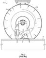
- Fig. 1 illustrates a rolling search unit 10 of the prior art having a wheel assembly with a tire 12 and components mounted within the tire, including ultrasonic transducers 14 and a heat exchanger 16 shown in phantom.
- the tire is filled with a coupling fluid 18, such as a mixture of water and ethylene glycol, which serves as the medium for propagation of ultrasonic beams between the transducers 14 and the tire 12.
- the function and purpose of the heat exchanger 16 is to maintain the coupling fluid 18 at a uniform temperature as described in greater detail in US Pat. 8,739,631 to Havira et al
- the tire 12 When the unit 10 is placed with a light load on a railhead H of an underlying rail to perform an inspection operation, the tire 12 is flattened slightly and forms a contact patch P with the rail head H.
- the tire 12 is made from a coupling fluid generates centrifugal forces which are exerted against the inner surface of the tire and stretch the tire. The stretching simultaneously increases the interior volume of the tire by finite amounts, and with a fixed volume of coupling fluid, the static pressure of the fluid inflating the tire is reduced.
- the arrows A illustrate the centrifugal forces of the coupling fluid 18 pressing outwardly against the tire 12 when the unit 10 is rotated as indicated by the arrow R.
- cupping C that is, a pucker or lifting of the tire membrane away from the rail head at the center of the contact patch P of the tire with the rail head, accompanies the reduction in static pressure as travel speed is increased.
- the cupping C is also illustrated in Fig. 2 .
- the cupping forms a pocket filled with a thicker layer of liquid couplant than desired and becomes a discontinuity of the medium in the path along which the ultrasonic beams B must pass between the transducers 14 and the rail head H. That discontinuity causes a distortion of the beam and reduction of the signal strength, and results in a loss of information sought by the inspection operation.
- US2013/220019 discloses a rolling search unit for railroad rail inspection.
- the rolling search unit comprises an ultrasonic device and a heat exchanger within a fluid-filled tire.
- the problems discussed above are addressed by an improved rolling search unit (hereafter RSU) for ultrasonic railroad rail inspection.
- the improved RSU comprises a wheel assembly having a tire filled with an ultrasonic coupling fluid.
- the wheel assembly is mounted by means of hubs for rotation on an axle for rolling contact of the tire with the head of an underlying rail of the railroad as the wheel assembly is translated along the rail during an inspection operation.
- the tire is made of a flexible membrane material, and forms a contact patch when placed on the head of the underlying rail during the inspection operation.
- An ultrasonic transducer is supported on the axle within the tire for propagating an ultrasonic beam through the coupling fluid and the tire into the head of the underlying rail, and for receiving ultrasonic beams reflected back from defects encountered in the underlying rail. The reflected beams revealing the defect can then be further analyzed to establish the criticality of the defect and to decide if any remedial steps need to be taken.
- a baffle is mounted in stationary relationship on the axle in the coupling fluid within the tire to suppress rotation of the coupling fluid with the tire when the tire rotates on the axle.
- the centrifugal forces that would otherwise be generated by the rotating fluid and be exerted outwardly against the tire are considerably reduced. Therefore, the flexible membrane material forming the tire is not significantly stretched at greater speeds, and the interior volume of the tire occupied by the fluid is not substantially expanded. As a consequence, the loss of static pressure within the tire is reduced or may be eliminated.
- the baffle With the baffle mounted on the axle and projecting from the axle into the coupling fluid, the baffle also intercepts stray ultrasonic beam reflections within the wheel assembly. By eliminating the stray reflections, the opportunity for the ultrasonic transducers to pick up the reflections and produce erroneous defect signals is also minimized.
- Figs. 1 and 2 illustrate a rolling search unit 10 of the prior art to illustrate the problems addressed by the improved rolling search unit as discussed above.
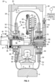
- Figs. 3 -6 illustrate the improved rolling search unit 20 (RSU) which incorporates the features of the present invention.
- the RSU 20 has all of the features of the prior art unit 10.
- the RSU 20 includes a wheel assembly 22 having a tire 12 filled with a coupling fluid 18 and a plurality of ultrasonic transducers 14 immersed in the fluid.
- the transducers generate ultrasonic beams B aimed in various downward directions to propagate through the fluid 18 and the tire 12 into the railhead H of an underlying rail in an inspection operation.
- the ultrasonic beams B When the ultrasonic beams B encounter a defect in the railhead or deeper in the rail they are reflected back through the rail, the tire 12, and the coupling fluid 18 to the transducers where the signal information carried by the reflected beams is captured and analyzed.
- the analyzed information can provide details regarding the type of defect, the size of the defect, and its location relative to the RSU.
- the wheel assembly 22 as shown most clearly in Figs. 3 - 6 is supported in a frame 24 with a leg 26 at the gauge side and a leg 28 at the field side, so that the legs straddle the wheel assembly.
- a stub axle 30 is connected to the gauge side leg 26 of the frame 24 as shown in Fig. 6 .
- Another stub axle 34 is similarly connected to the field side leg 28 of the frame.
- the stub axles 30, 34 are joined to each other at their inner ends by a bolt 38 shown in Fig. 5 .
- the stub axle 30 supports a number of components described hereafter within the tire 12 in stationary relationship with the frame 24.
- the floating axle projects out of the field side of the stub axle 34 and has a slotted flange 36 with a clamping screw 37 for trimming the mounting angle of the transducers by rotating the floating axle 42 within the stub axle 34 and then tightening the clamping screw 37 to fix the floating axle within the stub axle .
- the stub axles 30, 34 and the floating axle 42 are all fixed in stationary relationship to the frame 24.
- the axles and yoke are non-rotating and serve as a stationary mount for all of the internal components of the wheel assembly 22 including the transducers 14 and the heat exchanger 16.
- An electrical plug 44 is connected to the field side end of the stub axle 34 and provides electrical connections for the transducers 14 within the wheel assembly 22.
- the frame 24 with the wheel assembly 22, and typically multiple other similar wheel assemblies are suspended from a rail inspection carriage such as disclosed in US Published Patent Application 2019/0023286 during an inspection operation.
- the carriage is in turn suspended under a rail car or rail-mounted vehicle for traveling along the rails of a railroad and conducting an inspection of the rails in situ.
- the wheel assemblies are lowered into contact with the railheads H with a limited downward force that causes the tires of the wheel assemblies to flatten slightly, as shown most clearly in Fig. 5 , and forms the contact patch P of Figs. 1 and 2 .
- the contact patch is large enough to provide for favorable transmission of all the ultrasonic beams B penetrating the railhead from the tire.
- the wheel assembly 22 includes a wheel hub 50 on which the tire 12 is mounted at the gauge side, and hub 52 on which the tire 12 is mounted on the field side.
- the tire 12 is a flexible membrane material, such as polyurethane, that has been molded into the toroidal configuration with beads 54, 56 respectively at each circular edge.
- the hubs are provided with corresponding grooves for the beads.
- An annular clamping plate 58 with a groove matching the bead 54 clamps the bead against the wheel hub 50 in fluid-tight relationship by means of cap screws 60.
- a similar clamping plate 62 with a groove matching the bead 56 clamps the bead against the wheel hub 52 in fluid-tight relationship by means of similar cap screws 61.
- the hubs 50, 52, beads 54, 56, and clamping plates 58, 62 form a sealed connection between the tire 12 and hubs that prevents the coupling fluid 18 under pressure from escaping from the tire.
- a fill valve 64 is provided in the field side hub 52.
- the fill valve is a self-closing valve such as a Schrader valve.
- the field side hub 52 has a bleed valve 66 and a bleed port 68 leading from the valve to the interior of the tire.
- the bleed valve is a manually operated valve to open and close the port for bleeding air from the tire.
- the hub 50 is mounted on the stub axle 30 by means of roller bearing 70, and the hub 52 is mounted on the stub axle 34 by means of roller bearing 72.
- a shaft seal 74 is installed in the hub 50 to prevent coupling fluid from escaping through the bearing 70.
- a similar shaft seal 76 is installed in the hub 52 to prevent coupling fluid from escaping through the bearing 72.
- Other seals are provided at various joints between the bolts, valves, and axles to ensure that the coupling fluid 18 does not escape from the tire 12.
- an anti-rotation baffle 80 shown in Figs. 3-5 is supported in stationary relationship within the tire on the yoke 40 as seen most clearly in Figs. 3 and 4 .
- the baffle 80 projects radially outwardly from the axles toward the tire and has a shape that will generally obstruct the rotation of the coupling fluid with the tire.
- the baffle maintains a spaced relationship with the interior surface of the tire so that the baffle does not interfere with the rotation of the tire.
- the anti-rotation baffle 80 illustrated is flat, but curved and other shapes may also be employed to obtain the desired resistance to fluid rotation and maintain a spaced relationship with the interior of the tire 12.
- the shape of the baffle may also accommodate other components within the tire. Additionally, more than one baffle may be employed at different locations within the tire to suppress the fluid rotation.
- the anti-rotation baffle 80 also serves the purpose of intercepting and dissipating unwanted ultrasonic beam reflections within the tire.
- the baffle or baffles may be strategically shaped, positioned, and provided with a surface texture to accomplish the beam intercepting and dissipating functions.
- the RSU 20 has a pressure regulator for controlling the pressure of the coupling fluid 18 in the wheel assembly during an inspection operation.
- the pressure regulator includes a component 90 within the tire 12 and a regulated pressure source 100 outside of the wheel assembly on the frame 24 or elsewhere.
- the component 90 is a pressurizing bladder mounted on the stub axle 30 within the tire.
- the pressurizing bladder 90 has a housing 92 defining a pressure chamber 94 closed by a flexible diaphragm 96.
- the pressurizing bladder is preferably an air bladder supplied with pressurized air from the regulated pressure source 100 outside of the tire.
- pressurized air is delivered to the bladder 90, the diaphragm 96 expands into the interior space of the tire occupied by the coupling fluid and pressurizes the fluid.
- the regulated pressure source 100 in one embodiment is an air compressor that provides regulated air pressure. As shown most clearly in Fig. 5 , the pressurized air source 100 is connected to a fitting 102 on the gauge-side frame leg 26, and supplies regulated air pressure from outside the wheel assembly 22 to the pressurizing bladder 90 within the wheel assembly through a drilled channel 104 in the frame leg 26, and a manifold 106 formed in the stub axle 30.
- Fittings 112, 114 are used to feed a heating/cooling fluid through the heat exchanger 16 by means of similar but separate channels and manifolds in the stub axle 30.
- the heating or cooling is desirable to hold the temperature of the coupling fluid through which the ultrasonic beams B pass at a fixed level for standardized results since inspection of the rails is conducted in situ and may be performed in all seasons.
- the static pressure of the coupling fluid in the tire 12 is nominal, for example, 5-8 psi.
- the regulated pressure supplied from the pressure source 100 would be the same.
- the pressure source 100 supplies increased air pressure to the pressurizing bladder 90 and expands the flexible diaphragm 96 against the fluid within the tire.
- the regulated pressure source 100 receives a speed signal from a speed sensor 110 shown in Fig. 5 , which signal regulates the air pressure supplied by the source as a function of speed.
- the speed sensor 110 may be responsive to either the rotational speed of the wheel assembly 22 or the translational speed of the wheel assembly along the rail being inspected. In general the speed signal increases the regulated air pressure delivered by the pressure source with increased speeds.
- the pressure regulator formed by the pressurizing bladder 90 and regulated pressure source 100 maintains or increases the pressure in the tire to compensate for the finite increase in volume of the stretched tire and the otherwise associated reduction of pressure in the tire.
- the increased pressure at higher speeds presses the tire 12 against the rail head H and eliminates the cupping effect and the thicker layer of liquid couplant that would otherwise diminish the strength of the ultrasonic beams B and their reflections passing through the contact patch P.
- the anti-rotation baffle 80 is intended to prevent the coupling fluid from rotating with the tire 12, some of the fluid will pass by the baffle in view of the spaced relationship of the baffle and tire and could produce centrifugal forces expanding the tire. Therefore, it is advantageous to use both the baffle 80 and the pressurizing bladder 90 in the wheel assembly together.
- the internal component of the pressure regulator disclosed as the pressurizing bladder 90 and the regulated pressure source 100 can take various forms.
- the pressurizing component formed by the pressurizing baffle 90 may take the form of other expandable devices, such as a bellows, or a piston within or emerging from a cylinder for displacing or replacing fluid within the tire.
- the pressure source may also supply a pressurized liquid at a regulated pressure to activate the pressurizing component of the pressure regulator.
Landscapes
- Physics & Mathematics (AREA)
- Analytical Chemistry (AREA)
- Health & Medical Sciences (AREA)
- Life Sciences & Earth Sciences (AREA)
- Chemical & Material Sciences (AREA)
- Biochemistry (AREA)
- General Health & Medical Sciences (AREA)
- General Physics & Mathematics (AREA)
- Immunology (AREA)
- Pathology (AREA)
- Mechanical Engineering (AREA)
- Engineering & Computer Science (AREA)
- Acoustics & Sound (AREA)
- Investigating Or Analyzing Materials By The Use Of Ultrasonic Waves (AREA)
Description
- This application is a non-provisional application that claims the benefit of
United States Provisional Patent Application No. 62/990,805 filed March 17, 2020 - The present invention relates to improved apparatus and method for performing non-destructive testing and inspection of railroad rails. More particularly, the present invention is directed to a roller search unit (sometimes referred to as an RSU) and method for inspecting for and identifying defects in underlying railroad rails using ultrasonic transducers mounted within a wheel assembly having a fluid-filled tire. The fluid within the tires is an ultrasonic coupling fluid that transmits ultrasonic beams between the transducers and the tire. The beams penetrate the tire and the underlying rail, and are reflected back to the transducers from defects in the rail for analysis. In order to maximize signal strength of the ultrasonic beams transmitted back and forth between the transducers and tire, the coupling fluid must fully occupy the interior of the tire under all operating conditions.
- From time to time, and for various reasons, the rails of a railroad track may develop one or more detrimental flaws or defects. Such flaws may include transverse defects, vertical shear or split-head defects, horizontal shear or split-head defects or the like that may originate from manufacturing and construction processes, environmental factors or wear-and-tear from normal use. These flaws or defects are typically observed in the head of a rail, but may also be found within the web and foot of the rail, around the peripheries of the bolt holes, or any other portion of the cross-section of the rail. Due to the nature of railway travel, in which locomotives weighing tens of thousands of pounds regularly carry hundreds of tons of freight over rails while traveling at varying speeds, cracks within the rails may expand or propagate throughout the rail over time. Such flaws or defects that are left unattended or unaddressed can lead to a variety of problems, the most serious of which may include catastrophic rail failures or train derailments, and may pose serious financial, health and safety risks to goods and personnel, as well as the railway industry as a whole.
- Rail failures may be predicted and avoided through routine non-destructive inspection, which may enable railway operators to identify and cure hidden or infinitesimal flaws or defects within rails before they develop into problems of much greater magnitude. To detect such flaws or defects, vehicles or rail car-mounted rail inspection carriages including ultrasonic rail inspection equipment have been built to travel along a railroad track, and continuously perform ultrasonic inspection of the underlying rails in situ by transmitting ultrasonic beams into the rails and analyzing any portions of the beams that may be reflected off flaws or defects in the rail. One such rail inspection carriage is disclosed in
US Published Patent Application 2019/0023286 of Kocur et al. - One example of the ultrasonic rail inspection equipment for in situ rail inspection including a wheel assembly having a fluid-filled tire for maintaining rolling contact with the head of an underlying rail is disclosed in
United States Patent No. 7,849,748 B2 to Havira. According to the teachings of Havira, the tire forms a contact patch with a head of an underlying rail and includes an ultrasonic transducer supported within the tire for projecting an ultrasonic beam along a beam axis through the fluid, the tire, a liquid couplant sprayed between the tire and rail, and into the head of the underlying rail. The couplant is normally a thin layer of a liquid, such as water or a mixture of water and other reagents, for improved contact between the tire and rail head. The ultrasonic beam propagates through the underlying rail and is reflected by any defects or flaws that may be present therein, which may cause some or all of the beam signals to be returned to the transducer or received by an ultrasonic detector. The reflected beam signals are then analyzed by one or more computer processors to determine the type, magnitude, and location of the flaw or defect from which the beam was reflected. - When an ultrasonic transducer is suspended within a fluid-filled tire, such as is disclosed in Havira, the tire and fluid provide the transmission medium between the ultrasonic transducer and the underlying rail. Due to the nature of sound propagation, the strength and quality of the ultrasonic waves that are both delivered and received by the transducer depend upon a continuous medium or mediums for transmission. Air pockets and other discontinuities in the mediums through which the ultrasonic beams are propagated destroy the beams and the signal information carried by the beams.
- With slow speeds of travel during inspection operations, that is, less than 30 kph, the ultrasonic coupling fluid within the tire will generally maintain the necessary continuity of the medium with the tire for wave transmission. However, with higher speeds of travel sought in order to achieve shorter inspection times and less disruption to rail traffic, various problems develop.
-
Fig. 1 illustrates arolling search unit 10 of the prior art having a wheel assembly with atire 12 and components mounted within the tire, includingultrasonic transducers 14 and aheat exchanger 16 shown in phantom. As illustrated inFig. 2 , the tire is filled with acoupling fluid 18, such as a mixture of water and ethylene glycol, which serves as the medium for propagation of ultrasonic beams between thetransducers 14 and thetire 12. The function and purpose of theheat exchanger 16 is to maintain thecoupling fluid 18 at a uniform temperature as described in greater detail inUS Pat. 8,739,631 to Havira et al - When the
unit 10 is placed with a light load on a railhead H of an underlying rail to perform an inspection operation, thetire 12 is flattened slightly and forms a contact patch P with the rail head H. Thetire 12 is made from a coupling fluid generates centrifugal forces which are exerted against the inner surface of the tire and stretch the tire. The stretching simultaneously increases the interior volume of the tire by finite amounts, and with a fixed volume of coupling fluid, the static pressure of the fluid inflating the tire is reduced. InFig. 2 the arrows A illustrate the centrifugal forces of thecoupling fluid 18 pressing outwardly against thetire 12 when theunit 10 is rotated as indicated by the arrow R. - It has also been noted that a phenomenon referred to as "cupping" C, that is, a pucker or lifting of the tire membrane away from the rail head at the center of the contact patch P of the tire with the rail head, accompanies the reduction in static pressure as travel speed is increased. The cupping C is also illustrated in
Fig. 2 . The cupping forms a pocket filled with a thicker layer of liquid couplant than desired and becomes a discontinuity of the medium in the path along which the ultrasonic beams B must pass between thetransducers 14 and the rail head H. That discontinuity causes a distortion of the beam and reduction of the signal strength, and results in a loss of information sought by the inspection operation. - Another problem that arises with rolling inspection units of this type is the bouncing of ultrasonic beams within the
tire 12 due to reflections from various surfaces within the tire. The bouncing beams can be picked up by a transducer the same as, or other than, the one from which the beam emanated, and can be misinterpreted as a defect where one does not exist.US2013/220019 discloses a rolling search unit for railroad rail inspection. The rolling search unit comprises an ultrasonic device and a heat exchanger within a fluid-filled tire. - Remedies for the problems discussed above are offered by the features of an improved rolling search unit and method for ultrasonically inspecting railroad rails as described below.
- The problems discussed above are addressed by an improved rolling search unit (hereafter RSU) for ultrasonic railroad rail inspection. The improved RSU comprises a wheel assembly having a tire filled with an ultrasonic coupling fluid. The wheel assembly is mounted by means of hubs for rotation on an axle for rolling contact of the tire with the head of an underlying rail of the railroad as the wheel assembly is translated along the rail during an inspection operation. The tire is made of a flexible membrane material, and forms a contact patch when placed on the head of the underlying rail during the inspection operation.
- An ultrasonic transducer is supported on the axle within the tire for propagating an ultrasonic beam through the coupling fluid and the tire into the head of the underlying rail, and for receiving ultrasonic beams reflected back from defects encountered in the underlying rail. The reflected beams revealing the defect can then be further analyzed to establish the criticality of the defect and to decide if any remedial steps need to be taken.
- A baffle is mounted in stationary relationship on the axle in the coupling fluid within the tire to suppress rotation of the coupling fluid with the tire when the tire rotates on the axle. By suppressing the rotation of the fluid, the centrifugal forces that would otherwise be generated by the rotating fluid and be exerted outwardly against the tire are considerably reduced. Therefore, the flexible membrane material forming the tire is not significantly stretched at greater speeds, and the interior volume of the tire occupied by the fluid is not substantially expanded. As a consequence, the loss of static pressure within the tire is reduced or may be eliminated.
- With the baffle mounted on the axle and projecting from the axle into the coupling fluid, the baffle also intercepts stray ultrasonic beam reflections within the wheel assembly. By eliminating the stray reflections, the opportunity for the ultrasonic transducers to pick up the reflections and produce erroneous defect signals is also minimized.
- Dependent claims 2 to 7 describe advantageous embodiments of the rolling search unit.
- An improved method for inspecting railroad rail ultrasonically is also provided by the invention, see claim 8 and dependent claims 9 to 13.
- Further features and advantages of an improved rolling search unit and the method of conducting ultrasonic inspections of railroad rails can be derived from the following description.
-
-
Fig 1 is a perspective view from the field side of a rolling search unit according to the prior art on the head of a railroad rail while performing an ultrasonic inspection operation for defects in the rail. -
Fig. 2 is a cross sectional view transverse to the axis of rotation of the rolling search unit inFig. 1 . -
Fig. 3 is a perspective view of a rolling search unit in cross section with the field side portion of the unit cut away to show an anti-rotation baffle and a pressurizing bladder according to the present invention. -
Fig. 4 is a cross sectional view transverse to the axis of rotation of the rolling search unit with the field side of the unit removed as inFig. 3 . -
Fig. 5 is a cross sectional view along the axis of rotation of the rolling search unit inFig 3 . -
Fig. 6 is a perspective view from the gauge side of the rolling search unit inFig. 3 with the tire removed from the wheel hubs. -
Figs. 1 and2 illustrate a rollingsearch unit 10 of the prior art to illustrate the problems addressed by the improved rolling search unit as discussed above.Figs. 3 -6 illustrate the improved rolling search unit 20 (RSU) which incorporates the features of the present invention. TheRSU 20 has all of the features of theprior art unit 10. TheRSU 20 includes awheel assembly 22 having atire 12 filled with acoupling fluid 18 and a plurality ofultrasonic transducers 14 immersed in the fluid. The transducers generate ultrasonic beams B aimed in various downward directions to propagate through the fluid 18 and thetire 12 into the railhead H of an underlying rail in an inspection operation. - When the ultrasonic beams B encounter a defect in the railhead or deeper in the rail they are reflected back through the rail, the
tire 12, and thecoupling fluid 18 to the transducers where the signal information carried by the reflected beams is captured and analyzed. The analyzed information can provide details regarding the type of defect, the size of the defect, and its location relative to the RSU. - The
wheel assembly 22 as shown most clearly inFigs. 3 - 6 is supported in aframe 24 with aleg 26 at the gauge side and aleg 28 at the field side, so that the legs straddle the wheel assembly. Astub axle 30 is connected to thegauge side leg 26 of theframe 24 as shown inFig. 6 . Anotherstub axle 34 is similarly connected to thefield side leg 28 of the frame. Thestub axles bolt 38 shown inFig. 5 . Thestub axle 30 supports a number of components described hereafter within thetire 12 in stationary relationship with theframe 24. A floatingaxle 42 shown inFig. 5 is installed within thestub axle 34 and is connected through a cutaway section of the stub axle with ayoke 40 on which thetransducers 14 are mounted. The floating axle projects out of the field side of thestub axle 34 and has a slottedflange 36 with a clampingscrew 37 for trimming the mounting angle of the transducers by rotating the floatingaxle 42 within thestub axle 34 and then tightening the clampingscrew 37 to fix the floating axle within the stub axle . With the floating axle clamped with thestub axle 34, thestub axles axle 42 are all fixed in stationary relationship to theframe 24. The axles and yoke are non-rotating and serve as a stationary mount for all of the internal components of thewheel assembly 22 including thetransducers 14 and theheat exchanger 16. - An
electrical plug 44 is connected to the field side end of thestub axle 34 and provides electrical connections for thetransducers 14 within thewheel assembly 22. - It will be understood that the
frame 24 with thewheel assembly 22, and typically multiple other similar wheel assemblies, are suspended from a rail inspection carriage such as disclosed inUS Published Patent Application 2019/0023286 during an inspection operation. The carriage is in turn suspended under a rail car or rail-mounted vehicle for traveling along the rails of a railroad and conducting an inspection of the rails in situ. The wheel assemblies are lowered into contact with the railheads H with a limited downward force that causes the tires of the wheel assemblies to flatten slightly, as shown most clearly inFig. 5 , and forms the contact patch P ofFigs. 1 and2 . The contact patch is large enough to provide for favorable transmission of all the ultrasonic beams B penetrating the railhead from the tire. - As shown in
Fig. 5 , thewheel assembly 22 includes awheel hub 50 on which thetire 12 is mounted at the gauge side, andhub 52 on which thetire 12 is mounted on the field side. Thetire 12 is a flexible membrane material, such as polyurethane, that has been molded into the toroidal configuration withbeads annular clamping plate 58 with a groove matching thebead 54 clamps the bead against thewheel hub 50 in fluid-tight relationship by means of cap screws 60. Asimilar clamping plate 62 with a groove matching thebead 56 clamps the bead against thewheel hub 52 in fluid-tight relationship by means of similar cap screws 61. Together, thehubs beads plates tire 12 and hubs that prevents thecoupling fluid 18 under pressure from escaping from the tire. - To fill the tire with coupling fluid a
fill valve 64 is provided in thefield side hub 52. The fill valve is a self-closing valve such as a Schrader valve. To bleed air from thetire 12 when being filled with coupling fluid, thefield side hub 52 has ableed valve 66 and ableed port 68 leading from the valve to the interior of the tire. The bleed valve is a manually operated valve to open and close the port for bleeding air from the tire. - As shown in
Fig. 5 , to rotate thewheel assembly 22 in theframe 24 with thetire 12 against a railhead H during an inspection operation, thehub 50 is mounted on thestub axle 30 by means ofroller bearing 70, and thehub 52 is mounted on thestub axle 34 by means ofroller bearing 72. Ashaft seal 74 is installed in thehub 50 to prevent coupling fluid from escaping through thebearing 70. Asimilar shaft seal 76 is installed in thehub 52 to prevent coupling fluid from escaping through thebearing 72. Other seals are provided at various joints between the bolts, valves, and axles to ensure that thecoupling fluid 18 does not escape from thetire 12. - As previously indicated in connection with
Fig. 2 , shear forces between the tire andcoupling fluid 18 when thetire 12 rotates cause the fluid to rotate with the tire. The forces create centrifugal forces against the tire and stretch the tire by finite amounts. With a fixed volume of fluid, the static pressure of the fluid within the tire, typically 5-8 psi, will drop and risk the cupping C phenomenon, cavitation, and foaming within the tire, all of which interfere with the transmission of the ultrasonic beams B. - To suppress the rotation of the coupling fluid with the tire and the associated centrifugal forces, an
anti-rotation baffle 80 shown inFigs. 3-5 is supported in stationary relationship within the tire on theyoke 40 as seen most clearly inFigs. 3 and 4 . Thebaffle 80 projects radially outwardly from the axles toward the tire and has a shape that will generally obstruct the rotation of the coupling fluid with the tire. However, the baffle maintains a spaced relationship with the interior surface of the tire so that the baffle does not interfere with the rotation of the tire. By means of thebaffle 80 and the obstruction of the coupling fluid, the centrifugal forces of the fluid on the tire are considerably reduced along with the associated loss of static pressure within the tire. Hence the cupping phenomenon is suppressed and a continuous medium for transmission of the ultrasonic beams between the transducers and the railhead is maintained. - The
anti-rotation baffle 80 illustrated is flat, but curved and other shapes may also be employed to obtain the desired resistance to fluid rotation and maintain a spaced relationship with the interior of thetire 12. The shape of the baffle may also accommodate other components within the tire. Additionally, more than one baffle may be employed at different locations within the tire to suppress the fluid rotation. - In addition to preventing coupling fluid rotation, the
anti-rotation baffle 80 also serves the purpose of intercepting and dissipating unwanted ultrasonic beam reflections within the tire. The baffle or baffles may be strategically shaped, positioned, and provided with a surface texture to accomplish the beam intercepting and dissipating functions. - To further improve the continuity of the fluid medium through which the ultrasonic beams B pass between the
transducers 14 and thetire 12, theRSU 20 has a pressure regulator for controlling the pressure of thecoupling fluid 18 in the wheel assembly during an inspection operation. The pressure regulator includes acomponent 90 within thetire 12 and aregulated pressure source 100 outside of the wheel assembly on theframe 24 or elsewhere. As illustrated inFigs. 3-6 thecomponent 90 is a pressurizing bladder mounted on thestub axle 30 within the tire. As shown most clearly inFig. 5 , the pressurizingbladder 90 has ahousing 92 defining apressure chamber 94 closed by aflexible diaphragm 96. The pressurizing bladder is preferably an air bladder supplied with pressurized air from theregulated pressure source 100 outside of the tire. When pressurized air is delivered to thebladder 90, thediaphragm 96 expands into the interior space of the tire occupied by the coupling fluid and pressurizes the fluid. - The
regulated pressure source 100 in one embodiment is an air compressor that provides regulated air pressure. As shown most clearly inFig. 5 , thepressurized air source 100 is connected to a fitting 102 on the gauge-side frame leg 26, and supplies regulated air pressure from outside thewheel assembly 22 to the pressurizingbladder 90 within the wheel assembly through a drilledchannel 104 in theframe leg 26, and a manifold 106 formed in thestub axle 30. -
Fittings heat exchanger 16 by means of similar but separate channels and manifolds in thestub axle 30. The heating or cooling is desirable to hold the temperature of the coupling fluid through which the ultrasonic beams B pass at a fixed level for standardized results since inspection of the rails is conducted in situ and may be performed in all seasons. - When the
wheel assembly 22 is not in motion, the static pressure of the coupling fluid in thetire 12 is nominal, for example, 5-8 psi. The regulated pressure supplied from thepressure source 100 would be the same. However, when the wheel assembly is moving and centrifugal pressure of the rotating fluid causes the tire to stretch at higher inspection speeds, thepressure source 100 supplies increased air pressure to the pressurizingbladder 90 and expands theflexible diaphragm 96 against the fluid within the tire. - For this purpose the
regulated pressure source 100 receives a speed signal from aspeed sensor 110 shown inFig. 5 , which signal regulates the air pressure supplied by the source as a function of speed. Thespeed sensor 110 may be responsive to either the rotational speed of thewheel assembly 22 or the translational speed of the wheel assembly along the rail being inspected. In general the speed signal increases the regulated air pressure delivered by the pressure source with increased speeds. - In this manner, the pressure regulator formed by the pressurizing
bladder 90 andregulated pressure source 100 maintains or increases the pressure in the tire to compensate for the finite increase in volume of the stretched tire and the otherwise associated reduction of pressure in the tire. Correspondingly, the increased pressure at higher speeds presses thetire 12 against the rail head H and eliminates the cupping effect and the thicker layer of liquid couplant that would otherwise diminish the strength of the ultrasonic beams B and their reflections passing through the contact patch P. - While the present invention has been described in several embodiments, it will be understood that numerous modifications can be made without departing from the spirit of the invention. For example, although the
anti-rotation baffle 80 is intended to prevent the coupling fluid from rotating with thetire 12, some of the fluid will pass by the baffle in view of the spaced relationship of the baffle and tire and could produce centrifugal forces expanding the tire. Therefore, it is advantageous to use both thebaffle 80 and the pressurizingbladder 90 in the wheel assembly together. - The internal component of the pressure regulator disclosed as the pressurizing
bladder 90 and theregulated pressure source 100 can take various forms. The pressurizing component formed by the pressurizingbaffle 90 may take the form of other expandable devices, such as a bellows, or a piston within or emerging from a cylinder for displacing or replacing fluid within the tire. The pressure source may also supply a pressurized liquid at a regulated pressure to activate the pressurizing component of the pressure regulator. - Accordingly, the present invention has been described in several embodiments by way of illustration rather than limitation, limitation being given only by the appended claims.
Claims (13)
- A rolling search unit for ultrasonic railroad rail inspection comprising:a wheel assembly (22) having a tire (12) filled with an ultrasonic coupling fluid and rotatably mounted on an axle (30, 34) for rolling contact with a head (H) of an underlying rail of the railroad, the tire being made of a flexible membrane material, whereby the tire forms a contact patch (P) when placed on the head of the underlying rail during an inspection operation;an ultrasonic transducer (14) supported on the axle (30, 34) within the tire for propagating an ultrasonic beam (B) through the coupling fluid (18) and the tire into the head of the underlying rail, and for receiving ultrasonic beams reflected back from defects detected in the underlying rail; and characterized bya baffle (80) mounted in stationary relationship on the axle in the coupling fluid (18) within the tire to suppress rotation of the coupling fluid with the tire when the tire rotates on the axle.
- A rolling search unit for ultrasonic railroad rail inspection as defined in Claim 1 wherein the baffle (18) is mounted on the axle (30) to project into the coupling fluid and intercept ultrasonic wave reflections within the wheel assembly (22).
- A rolling search unit for ultrasonic railroad rail inspection as defined in Claim 1 further including a pressure regulator (90, 100) for regulating the pressure of the coupling fluid within the wheel assembly during an inspection operation.
- A rolling search unit for ultrasonic railroad rail inspection as defined in Claim 3 wherein the pressure regulator includes a pressurizing component (90) mounted in the coupling fluid within the tire (12) of the wheel assembly.
- A rolling search unit for ultrasonic railroad rail inspection as defined in Claim 4 wherein the pressurizing component (90) is mounted on the axle within the tire (12), and the axle (30) serves as a manifold with passageways leading from the exterior of the rolling search unit to the pressurizing component within the tire for supplying a pressurizing fluid to the component.
- A rolling search unit for ultrasonic railroad rail inspection as defined in Claim 5 wherein the pressure regulator (90, 100) further includes a source (100) of fluid at a regulated pressure outside the wheel assembly (22) connected with the pressurizing component (90) within the wheel assembly for pressurizing the coupling fluid within the wheel assembly at a selected pressure level established by the source.
- A rolling search unit for ultrasonic railroad rail inspection as defined in Claim 6 wherein the source (100) of fluid provides fluid to the pressurizing component at a regulated pressure that is variable, and wherein the source of fluid at the regulated pressure includes a speed sensor (110) detecting the speed of the rolling search unit (22) during an inspection operation, and the source (100) regulates the fluid pressure pressurizing the pressurizing component (90) as a function of the detected speed.
- A method for inspecting railroad rail ultrasonically comprising the steps of:providing a wheel assembly (22) having a tire (12) filled with an ultrasonic coupling fluid (18) and mounted for rotation on an axle (30, 34) for rolling contact with a head (H) of an underlying rail of the railroad, the tire being made of a flexible membrane material, whereby the tire forms a contact patch (P) when placed on the head of the underlying rail during an inspection operation;placing an ultrasonic transducer (14) within the tire for propagating an ultrasonic beam (B) through the coupling fluid and the tire into the head (H) of the underlying rail, and for receiving ultrasonic waves reflected back from defects in the underlying rail;providing a baffle (18) mounted in stationary relationship on the axle in the coupling fluid within the tire to suppress rotation of the coupling fluid with the tire when the tire rotates on the axle; androlling the wheel assembly (22) along a railroad rail with the tire in contact with the head of the rail while the transducer (14) is activated in an inspection operation, andpressurizing the ultrasonic coupling fluid within the tire to a regulated pressure during the inspection operation.
- A method for inspecting railroad rail ultrasonically as defined in Claim 8 wherein the pressurizing of the ultrasonic coupling fluid (18) is regulated as function of the translational speed of the wheel assembly (22) along the railroad rail.
- A method for inspecting railroad rail ultrasonically as defined in Claim 8 wherein the pressurizing of the ultrasonic coupling fluid is regulated as function of the rotational speed of the wheel assembly (22) while rolling along the railroad rail.
- A method for inspecting railroad rail ultrasonically as defined in Claim 8 wherein the pressurizing of the ultrasonic coupling fluid is regulated as function of the speed of the wheel assembly (22) along the railroad rail with pressure being increased with increases in speed.
- A method for inspecting railroad rail ultrasonically as defined in Claim 8 wherein the pressurizing of the ultrasonic coupling fluid is accomplished by a pressurizing component mounted within the wheel assembly (22).
- A method for inspecting railroad rail ultrasonically as defined in Claim 12 wherein the pressurizing component is a bladder (90).
Priority Applications (1)
| Application Number | Priority Date | Filing Date | Title |
|---|---|---|---|
| EP23217517.4A EP4317962B1 (en) | 2020-03-17 | 2020-12-04 | Rolling search unit for ultrasonic railroad rail inspection |
Applications Claiming Priority (3)
| Application Number | Priority Date | Filing Date | Title |
|---|---|---|---|
| US202062990805P | 2020-03-17 | 2020-03-17 | |
| US16/863,307 US11333635B2 (en) | 2020-03-17 | 2020-04-30 | Rolling search unit for ultrasonic railroad rail inspection |
| PCT/US2020/063223 WO2021188167A1 (en) | 2020-03-17 | 2020-12-04 | Rolling search unit for ultrasonic railroad rail inspection |
Related Child Applications (2)
| Application Number | Title | Priority Date | Filing Date |
|---|---|---|---|
| EP23217517.4A Division-Into EP4317962B1 (en) | 2020-03-17 | 2020-12-04 | Rolling search unit for ultrasonic railroad rail inspection |
| EP23217517.4A Division EP4317962B1 (en) | 2020-03-17 | 2020-12-04 | Rolling search unit for ultrasonic railroad rail inspection |
Publications (4)
| Publication Number | Publication Date |
|---|---|
| EP4031432A1 EP4031432A1 (en) | 2022-07-27 |
| EP4031432A4 EP4031432A4 (en) | 2023-10-18 |
| EP4031432B1 true EP4031432B1 (en) | 2025-01-29 |
| EP4031432C0 EP4031432C0 (en) | 2025-01-29 |
Family
ID=77746634
Family Applications (2)
| Application Number | Title | Priority Date | Filing Date |
|---|---|---|---|
| EP23217517.4A Active EP4317962B1 (en) | 2020-03-17 | 2020-12-04 | Rolling search unit for ultrasonic railroad rail inspection |
| EP20925581.9A Active EP4031432B1 (en) | 2020-03-17 | 2020-12-04 | Rolling search unit for ultrasonic railroad rail inspection |
Family Applications Before (1)
| Application Number | Title | Priority Date | Filing Date |
|---|---|---|---|
| EP23217517.4A Active EP4317962B1 (en) | 2020-03-17 | 2020-12-04 | Rolling search unit for ultrasonic railroad rail inspection |
Country Status (6)
| Country | Link |
|---|---|
| US (1) | US11333635B2 (en) |
| EP (2) | EP4317962B1 (en) |
| CN (2) | CN114761304B (en) |
| AU (1) | AU2020435919B2 (en) |
| BR (1) | BR112022008055B1 (en) |
| WO (1) | WO2021188167A1 (en) |
Families Citing this family (4)
| Publication number | Priority date | Publication date | Assignee | Title |
|---|---|---|---|---|
| US12240505B2 (en) * | 2019-02-10 | 2025-03-04 | Scanmaster Systems (Irt) Ltd. | Low maintenance rail monitoring probe |
| WO2021162966A1 (en) * | 2020-02-13 | 2021-08-19 | Hyperloop Technologies, Inc. | System and method for guidance control on a wheeled bogie |
| CA3243242A1 (en) * | 2022-01-25 | 2023-08-03 | Herzog Services, Inc. | Roller search unit having integrated digital circuitry for detecting rail defects |
| CN119218653A (en) * | 2024-10-24 | 2024-12-31 | 广东井岗智能精密有限公司 | Aluminum alloy component processing quality detection device |
Family Cites Families (27)
| Publication number | Priority date | Publication date | Assignee | Title |
|---|---|---|---|---|
| US3442119A (en) * | 1965-10-11 | 1969-05-06 | Automation Ind Inc | Ultrasonic search wheel assembly |
| US4165648A (en) * | 1977-07-25 | 1979-08-28 | Pagano Dominick A | Two wheel ultrasonic rail testing system and method |
| GB2055201B (en) * | 1979-07-19 | 1983-07-20 | British Gas Corp | Pressure-balanced probe |
| SU1605186A1 (en) * | 1988-01-25 | 1990-11-07 | Ленинградский институт инженеров железнодорожного транспорта им.акад.В.Н.Образцова | Ultrasonic rolling transducer |
| JP2637553B2 (en) * | 1989-04-24 | 1997-08-06 | 三菱重工業株式会社 | Ultrasonic flaw detector |
| US5386727A (en) * | 1992-06-02 | 1995-02-07 | Herzog Contracting Corporation | Dynamic rail longitudinal stress measuring system |
| US5419196A (en) * | 1993-03-19 | 1995-05-30 | Pandrol Jackson Technologies, Inc. | Ultrasonic side-looker for rail head flaw detection |
| US5578758A (en) * | 1995-06-21 | 1996-11-26 | Pandrol Jackson Technologies, Inc. | Rail investigating ultrasonic transducer |
| US6055862A (en) * | 1996-06-10 | 2000-05-02 | Herzog Services, Inc. | Method of and an apparatus for detecting, identifying and recording the location of defects in a railway rail |
| JPH10267905A (en) * | 1997-03-21 | 1998-10-09 | Tokimec Inc | Ultrasonic tire prove |
| JP2002528717A (en) * | 1998-10-23 | 2002-09-03 | リ、ガン | Ultrasonic flaw detection method for ultrasonically detecting rail flaws, wheel converter and flaw detection apparatus |
| AU9619598A (en) * | 1998-10-23 | 2000-05-15 | Gang Li | Method, transducer wheel and flaw detection system for ultrasonic detecting railroad rails |
| AU2002213064A1 (en) * | 2000-10-10 | 2002-04-22 | Sperry Rail, Inc. | Hi-rail vehicle-based rail inspection system |
| DE102004061870B3 (en) * | 2004-12-22 | 2006-06-14 | Siemens Ag | Sensor wheel for the acoustic examination of a test object and use of the sensor wheel |
| CN101320020A (en) * | 2007-06-07 | 2008-12-10 | 章罕 | Ultrasonic wheel type probe |
| US7849748B2 (en) * | 2008-05-15 | 2010-12-14 | Sperry Rail, Inc. | Method of and an apparatus for in situ ultrasonic rail inspection of a railroad rail |
| US7882742B1 (en) * | 2008-10-28 | 2011-02-08 | Herzog Services, Inc. | Apparatus for detecting, identifying and recording the location of defects in a railway rail |
| US8485035B2 (en) * | 2011-08-22 | 2013-07-16 | Herzog Services, Inc. | Method of detecting defects |
| US8739631B2 (en) | 2012-02-28 | 2014-06-03 | Sperry Rail, Inc. | System and method for non-destructive testing of railroad rails using ultrasonic apparatuses mounted within fluid-filled tires maintained at constant temperatures |
| CN104713952A (en) * | 2013-12-16 | 2015-06-17 | 中国铁道科学研究院 | Double-wave wheel type probe for steel rail flaw detection |
| CN106471365B (en) * | 2014-03-17 | 2019-07-26 | 索尼迈克斯有限责任公司 | Removable ultrasonic track detection system and method |
| CN204389450U (en) * | 2015-02-12 | 2015-06-10 | 赵胤波 | Ultrasonic wheel type probe |
| US20160305915A1 (en) * | 2015-04-16 | 2016-10-20 | Transportation Technology Center, Inc. | System for inspecting rail with phased array ultrasonics |
| WO2017123879A1 (en) | 2016-01-15 | 2017-07-20 | Sperry Rail, Inc. | An adaptive rail inspection carriage |
| CN205720107U (en) * | 2016-06-15 | 2016-11-23 | 天津亚标机器人有限公司 | A kind of rail defect non-destructive ultrasonic array detection equipment |
| CN207366511U (en) * | 2017-07-17 | 2018-05-15 | 广东汕头超声电子股份有限公司 | A kind of rail wheel seach unit |
| CN110658262B (en) * | 2019-10-23 | 2025-07-25 | 北京地平线轨道技术有限公司 | Wheel support is visited to rail ultrasonic flaw detector |
-
2020
- 2020-04-30 US US16/863,307 patent/US11333635B2/en active Active
- 2020-12-04 WO PCT/US2020/063223 patent/WO2021188167A1/en not_active Ceased
- 2020-12-04 CN CN202080084405.1A patent/CN114761304B/en active Active
- 2020-12-04 EP EP23217517.4A patent/EP4317962B1/en active Active
- 2020-12-04 CN CN202311037256.5A patent/CN117022374B/en active Active
- 2020-12-04 AU AU2020435919A patent/AU2020435919B2/en active Active
- 2020-12-04 BR BR112022008055-7A patent/BR112022008055B1/en active IP Right Grant
- 2020-12-04 EP EP20925581.9A patent/EP4031432B1/en active Active
Also Published As
| Publication number | Publication date |
|---|---|
| CA3158469A1 (en) | 2021-09-23 |
| CN114761304A (en) | 2022-07-15 |
| AU2020435919A1 (en) | 2022-06-02 |
| US20210293758A1 (en) | 2021-09-23 |
| AU2020435919B2 (en) | 2023-10-12 |
| BR112022008055A2 (en) | 2022-07-12 |
| EP4317962B1 (en) | 2025-10-22 |
| EP4031432A1 (en) | 2022-07-27 |
| BR112022008055B1 (en) | 2024-03-05 |
| EP4317962A2 (en) | 2024-02-07 |
| EP4317962C0 (en) | 2025-10-22 |
| CN114761304B (en) | 2023-10-03 |
| EP4031432A4 (en) | 2023-10-18 |
| US11333635B2 (en) | 2022-05-17 |
| WO2021188167A1 (en) | 2021-09-23 |
| CN117022374B (en) | 2025-09-23 |
| CN117022374A (en) | 2023-11-10 |
| EP4031432C0 (en) | 2025-01-29 |
| EP4317962A3 (en) | 2024-04-10 |
Similar Documents
| Publication | Publication Date | Title |
|---|---|---|
| EP4317962B1 (en) | Rolling search unit for ultrasonic railroad rail inspection | |
| CA2860073C (en) | System and method for non-destructive testing of railroad rails using ultrasonic apparatuses mounted within fluid-filled tires maintained at constant temperatures | |
| EP2277037B1 (en) | Method of and an apparatus for in situ ultrasonic rail inspection of a railroad rail | |
| US6055862A (en) | Method of and an apparatus for detecting, identifying and recording the location of defects in a railway rail | |
| WO1990013814A1 (en) | Ultrasonic wheel testing | |
| CA3158469C (en) | Rolling search unit for ultrasonic railroad rail inspection | |
| US20040244491A1 (en) | Apparatus and method for ultrasonic inspection | |
| KR20240081995A (en) | Ultrasonic inspection module for wheel defect of railroad vehicle and method for inspecting using the same | |
| CN202994731U (en) | System for ultrasonic inspection of railway rails and railway rail inspection system | |
| Würschig | Smart inspection of rail wheels with matrix arrays | |
| JP6770462B2 (en) | Inspection method for laminated elastic bodies | |
| HK1231444A1 (en) | Axle of wheel sets and respective method for the ultrasound inspection | |
| HK1186242B (en) | System and method for non-destructive testing of railroad rails | |
| Reis et al. | Acousto-ultrasonic damage evaluation of steel-belted radial tires | |
| JPH11201950A (en) | Load support | |
| Borodin et al. | Acoustic-emission testing of wheel pairs disks of freight cars. | |
| HK1231444B (en) | Axle of wheel sets and respective method for the ultrasound inspection |
Legal Events
| Date | Code | Title | Description |
|---|---|---|---|
| STAA | Information on the status of an ep patent application or granted ep patent |
Free format text: STATUS: THE INTERNATIONAL PUBLICATION HAS BEEN MADE |
|
| PUAI | Public reference made under article 153(3) epc to a published international application that has entered the european phase |
Free format text: ORIGINAL CODE: 0009012 |
|
| STAA | Information on the status of an ep patent application or granted ep patent |
Free format text: STATUS: REQUEST FOR EXAMINATION WAS MADE |
|
| 17P | Request for examination filed |
Effective date: 20220419 |
|
| AK | Designated contracting states |
Kind code of ref document: A1 Designated state(s): AL AT BE BG CH CY CZ DE DK EE ES FI FR GB GR HR HU IE IS IT LI LT LU LV MC MK MT NL NO PL PT RO RS SE SI SK SM TR |
|
| DAV | Request for validation of the european patent (deleted) | ||
| DAX | Request for extension of the european patent (deleted) | ||
| A4 | Supplementary search report drawn up and despatched |
Effective date: 20230914 |
|
| RIC1 | Information provided on ipc code assigned before grant |
Ipc: G01N 29/34 20060101ALI20230908BHEP Ipc: G01N 29/265 20060101ALI20230908BHEP Ipc: G01N 29/24 20060101ALI20230908BHEP Ipc: G01N 21/88 20060101ALI20230908BHEP Ipc: B61K 9/10 20060101AFI20230908BHEP |
|
| GRAP | Despatch of communication of intention to grant a patent |
Free format text: ORIGINAL CODE: EPIDOSNIGR1 |
|
| STAA | Information on the status of an ep patent application or granted ep patent |
Free format text: STATUS: GRANT OF PATENT IS INTENDED |
|
| INTG | Intention to grant announced |
Effective date: 20240911 |
|
| GRAS | Grant fee paid |
Free format text: ORIGINAL CODE: EPIDOSNIGR3 |
|
| GRAA | (expected) grant |
Free format text: ORIGINAL CODE: 0009210 |
|
| STAA | Information on the status of an ep patent application or granted ep patent |
Free format text: STATUS: THE PATENT HAS BEEN GRANTED |
|
| AK | Designated contracting states |
Kind code of ref document: B1 Designated state(s): AL AT BE BG CH CY CZ DE DK EE ES FI FR GB GR HR HU IE IS IT LI LT LU LV MC MK MT NL NO PL PT RO RS SE SI SK SM TR |
|
| REG | Reference to a national code |
Ref country code: GB Ref legal event code: FG4D |
|
| REG | Reference to a national code |
Ref country code: CH Ref legal event code: EP |
|
| REG | Reference to a national code |
Ref country code: DE Ref legal event code: R096 Ref document number: 602020045682 Country of ref document: DE |
|
| REG | Reference to a national code |
Ref country code: IE Ref legal event code: FG4D |
|
| U01 | Request for unitary effect filed |
Effective date: 20250204 |
|
| U07 | Unitary effect registered |
Designated state(s): AT BE BG DE DK EE FI FR IT LT LU LV MT NL PT RO SE SI Effective date: 20250210 |
|
| PG25 | Lapsed in a contracting state [announced via postgrant information from national office to epo] |
Ref country code: RS Free format text: LAPSE BECAUSE OF FAILURE TO SUBMIT A TRANSLATION OF THE DESCRIPTION OR TO PAY THE FEE WITHIN THE PRESCRIBED TIME-LIMIT Effective date: 20250429 |
|
| PG25 | Lapsed in a contracting state [announced via postgrant information from national office to epo] |
Ref country code: PL Free format text: LAPSE BECAUSE OF FAILURE TO SUBMIT A TRANSLATION OF THE DESCRIPTION OR TO PAY THE FEE WITHIN THE PRESCRIBED TIME-LIMIT Effective date: 20250129 |
|
| PG25 | Lapsed in a contracting state [announced via postgrant information from national office to epo] |
Ref country code: ES Free format text: LAPSE BECAUSE OF FAILURE TO SUBMIT A TRANSLATION OF THE DESCRIPTION OR TO PAY THE FEE WITHIN THE PRESCRIBED TIME-LIMIT Effective date: 20250129 |
|
| PG25 | Lapsed in a contracting state [announced via postgrant information from national office to epo] |
Ref country code: IS Free format text: LAPSE BECAUSE OF FAILURE TO SUBMIT A TRANSLATION OF THE DESCRIPTION OR TO PAY THE FEE WITHIN THE PRESCRIBED TIME-LIMIT Effective date: 20250529 |
|
| PG25 | Lapsed in a contracting state [announced via postgrant information from national office to epo] |
Ref country code: HR Free format text: LAPSE BECAUSE OF FAILURE TO SUBMIT A TRANSLATION OF THE DESCRIPTION OR TO PAY THE FEE WITHIN THE PRESCRIBED TIME-LIMIT Effective date: 20250129 |
|
| PG25 | Lapsed in a contracting state [announced via postgrant information from national office to epo] |
Ref country code: GR Free format text: LAPSE BECAUSE OF FAILURE TO SUBMIT A TRANSLATION OF THE DESCRIPTION OR TO PAY THE FEE WITHIN THE PRESCRIBED TIME-LIMIT Effective date: 20250430 |
|
| PG25 | Lapsed in a contracting state [announced via postgrant information from national office to epo] |
Ref country code: SM Free format text: LAPSE BECAUSE OF FAILURE TO SUBMIT A TRANSLATION OF THE DESCRIPTION OR TO PAY THE FEE WITHIN THE PRESCRIBED TIME-LIMIT Effective date: 20250129 |
|
| PG25 | Lapsed in a contracting state [announced via postgrant information from national office to epo] |
Ref country code: CZ Free format text: LAPSE BECAUSE OF FAILURE TO SUBMIT A TRANSLATION OF THE DESCRIPTION OR TO PAY THE FEE WITHIN THE PRESCRIBED TIME-LIMIT Effective date: 20250129 |
|
| PG25 | Lapsed in a contracting state [announced via postgrant information from national office to epo] |
Ref country code: SK Free format text: LAPSE BECAUSE OF FAILURE TO SUBMIT A TRANSLATION OF THE DESCRIPTION OR TO PAY THE FEE WITHIN THE PRESCRIBED TIME-LIMIT Effective date: 20250129 |
|
| PLBE | No opposition filed within time limit |
Free format text: ORIGINAL CODE: 0009261 |
|
| STAA | Information on the status of an ep patent application or granted ep patent |
Free format text: STATUS: NO OPPOSITION FILED WITHIN TIME LIMIT |
|
| REG | Reference to a national code |
Ref country code: CH Ref legal event code: L10 Free format text: ST27 STATUS EVENT CODE: U-0-0-L10-L00 (AS PROVIDED BY THE NATIONAL OFFICE) Effective date: 20251210 |
|
| REG | Reference to a national code |
Ref country code: CH Ref legal event code: U11 Free format text: ST27 STATUS EVENT CODE: U-0-0-U10-U11 (AS PROVIDED BY THE NATIONAL OFFICE) Effective date: 20260101 |
|
| 26N | No opposition filed |
Effective date: 20251030 |
|
| PGFP | Annual fee paid to national office [announced via postgrant information from national office to epo] |
Ref country code: GB Payment date: 20251219 Year of fee payment: 6 |
|
| PGFP | Annual fee paid to national office [announced via postgrant information from national office to epo] |
Ref country code: IE Payment date: 20251219 Year of fee payment: 6 |
|
| U20 | Renewal fee for the european patent with unitary effect paid |
Year of fee payment: 6 Effective date: 20251230 |
|
| PGFP | Annual fee paid to national office [announced via postgrant information from national office to epo] |
Ref country code: NO Payment date: 20251230 Year of fee payment: 6 |
|
| PGFP | Annual fee paid to national office [announced via postgrant information from national office to epo] |
Ref country code: CH Payment date: 20260101 Year of fee payment: 6 |