EP4031417B1 - Ecran de protection acoustique pour moteur de véhicule automobile - Google Patents
Ecran de protection acoustique pour moteur de véhicule automobile Download PDFInfo
- Publication number
- EP4031417B1 EP4031417B1 EP20820267.1A EP20820267A EP4031417B1 EP 4031417 B1 EP4031417 B1 EP 4031417B1 EP 20820267 A EP20820267 A EP 20820267A EP 4031417 B1 EP4031417 B1 EP 4031417B1
- Authority
- EP
- European Patent Office
- Prior art keywords
- screen
- engine
- acoustic
- fixing
- central opening
- Prior art date
- Legal status (The legal status is an assumption and is not a legal conclusion. Google has not performed a legal analysis and makes no representation as to the accuracy of the status listed.)
- Active
Links
Images



Classifications
-
- B—PERFORMING OPERATIONS; TRANSPORTING
- B60—VEHICLES IN GENERAL
- B60R—VEHICLES, VEHICLE FITTINGS, OR VEHICLE PARTS, NOT OTHERWISE PROVIDED FOR
- B60R13/00—Elements for body-finishing, identifying, or decorating; Arrangements or adaptations for advertising purposes
- B60R13/08—Insulating elements, e.g. for sound insulation
- B60R13/0838—Insulating elements, e.g. for sound insulation for engine compartments
-
- B—PERFORMING OPERATIONS; TRANSPORTING
- B60—VEHICLES IN GENERAL
- B60R—VEHICLES, VEHICLE FITTINGS, OR VEHICLE PARTS, NOT OTHERWISE PROVIDED FOR
- B60R21/00—Arrangements or fittings on vehicles for protecting or preventing injuries to occupants or pedestrians in case of accidents or other traffic risks
- B60R21/34—Protecting non-occupants of a vehicle, e.g. pedestrians
-
- B—PERFORMING OPERATIONS; TRANSPORTING
- B60—VEHICLES IN GENERAL
- B60R—VEHICLES, VEHICLE FITTINGS, OR VEHICLE PARTS, NOT OTHERWISE PROVIDED FOR
- B60R21/00—Arrangements or fittings on vehicles for protecting or preventing injuries to occupants or pedestrians in case of accidents or other traffic risks
- B60R21/34—Protecting non-occupants of a vehicle, e.g. pedestrians
- B60R2021/343—Protecting non-occupants of a vehicle, e.g. pedestrians using deformable body panel, bodywork or components
Definitions
- the invention relates to an acoustic protection screen for a motor vehicle engine, as well as an assembly comprising an engine provided with such a screen and a method of manufacturing such a screen.
- Acoustic protection screens for motor vehicle engines are intended to cover the upper part of the engine. They perform several functions.
- a first function is their aesthetic function. They in fact hide the engine from the view of users.
- a second function is their acoustic function. In fact, a layer of acoustic absorbent material is generally integrated into said screens and makes it possible to attenuate the noise generated by the engine.
- a third function is their protective function. In particular, during an impact with a pedestrian, it may happen that the pedestrian's head hits the hood in an area located just above the screen. The screen thus protects the engine during impact, but above all cushions the impact and, therefore, protects the pedestrian.
- the protective screen is made entirely of polyurethane foam. It is connected to the motor by a plug-in coupling device. This device consists of a stud and a mounting pin. The mounting pin is fixed to the upper part of the motor so that it is oriented vertically and upwards.
- the protective screen has on its internal face a hollow stud which fits onto the mounting pin and holds the screen in place.
- This type of screen has the disadvantage of being fragile due to their constituent material being only foam. Furthermore, this foam material does not ensure robust fixation of the hollow pad on the screen. In addition, it is generally difficult to affix an inscription or a coat of paint to this foam material: the aesthetics of the screen are therefore reduced.
- Another known type of screen described in the patent FR 2 979 086 corresponding to the preamble of claim 1, combines the use of a frame of plastic material surrounding a layer of material acoustic absorber.
- the plastic material frame extending only to the periphery of the layer of acoustic absorbing material, it is always difficult to apply a decoration to the visible part of the screen.
- this type of screen requires the implementation of a relatively complex manufacturing process due to the non-homogeneous structure of the layer of acoustic absorbing material, which has two zones of different density.
- the object of the present invention is to propose an acoustic protection screen which does not present the disadvantages of the prior art cited above.
- the invention proposes an acoustic protection screen for a motor vehicle engine comprising the characteristics of claim 1.
- the protective screen of the invention has both increased rigidity, due to the use of a plastic material, and better flexibility, particularly at the level of a central upper zone, allowing it to 'absorb shock more effectively during a pedestrian impact. It also has the advantage of being easy to make.
- the invention also relates to an assembly comprising a motor provided with a screen as defined above, in which the means for fixing the screen cooperate with complementary fixing means secured to the motor so as to ensure the fixing of said screen on said engine.
- the means for fixing the screen comprise at least one stud having a housing intended to receive in interlocking a pin secured to the motor.
- a hot part of the engine is covered by at least one end zone of the first part of the screen.
- step e) is replaced by a step f'), succeeding step f) and carried out prior to step g), during which the acoustic absorbing material is injected in the mold formed by the lower and upper dies.
- an acoustic protection screen 1 is arranged on a motor vehicle engine 2 and under a hood (not shown).
- the screen 1 comprises a first part 3 made of plastic material, in particular polyamide, and a second part 4 made of an acoustic absorbing material.
- the first part 3 covers the second part 4 so as to mask it at least partially. It also has a central opening 32 serving as accommodation for a third part 5, said third part 5 being formed in a deformable material making it possible to effectively absorb the shocks transmitted by the hood of the motor vehicle.
- a deformable material will be a fibrous material, preferably based on glass fibers, with a surface mass of between 400 and 1000 g/m 2 .
- the first part 3 comprises two side edges 31 with a curved profile.
- Each of the side edges 31 comprises a main segment 311 adjoining the central opening 32 and a first end segment 312 adjoining the main segment 311 and oriented perpendicularly thereto, said first end segment 312 forming a peripheral edge of the screen 1.
- the end segment 312 adjoins, without touching it, the motor 2.
- the space separating the main segment 311 and the first end segment 312 of the motor 2 is entirely or almost entirely occupied by the second part 4.
- Each of the side edges 31 also comprises a second end segment 314 oriented perpendicular to the main segment 311, said second end segment 314 having a substantially cylindrical shape and extending from the main segment 311 downwards towards the motor 2. It passes right through the second part 4.
- the free end 315 is configured to form a housing for a pin 6 fixed on the motor 2, thus allowing the fixing of the screen 1 on the motor 2.
- said free end 315 will receive a hollow stud into which the pin 6 will fit.
- the first part 3 may comprise at least one end zone intended to cover a hot part of the engine 2. This end zone could for example form an extension of one of the side edges 31.
- the second part 4 has on its lower face 41, which is in contact with the motor 2, a profile substantially complementary to that of the upper face of the motor 2. It occupies all or almost all of the space separating the first and third parts 3, 5 of the motor 2. It is preferably made of a polyurethane foam material with a density of between 70 and 200 kg/m 3 .
- step 108 may be followed by a step consisting of assembling hollow blocks at the free ends 315 of the second end segments 314 and/or a step of forming a decoration on the upper face of the screen 1.
- step 106 could be replaced by an intermediate step, carried out after step 107 and before step 108, during which the acoustic absorbing material is injected into the mold formed by the lower and upper dies. 11, 12.
- FIG. 3 there is shown a diagram showing the variations in the acoustic gain (expressed in dB) as a function of the frequency (expressed in Hz) of an acoustic wave passing through a protective screen according to the invention (example 1) and, in comparison, those obtained when the same acoustic wave passes through a conventional protective screen (comparative example), formed of a plastic frame inside which an acoustic absorbent material based on fibers is imprisoned, as described for example in the application of patent FR 2 979 086 .
- the acoustic gain of the screen according to the invention is at least 5 dB greater than that of the conventional screen.
- the acoustic gain of the screen according to the invention remains greater than that of the conventional screen but the difference between the two gains is, in this case, less than 5 dB.
- the protective screen of the invention therefore has the additional advantage of more effectively attenuating the noise generated by the engine.
Landscapes
- Engineering & Computer Science (AREA)
- Mechanical Engineering (AREA)
- Physics & Mathematics (AREA)
- Acoustics & Sound (AREA)
- Vehicle Interior And Exterior Ornaments, Soundproofing, And Insulation (AREA)
- Superstructure Of Vehicle (AREA)
- Fittings On The Vehicle Exterior For Carrying Loads, And Devices For Holding Or Mounting Articles (AREA)
- Casings For Electric Apparatus (AREA)
Description
- L'invention concerne un écran de protection acoustique pour moteur de véhicule automobile, ainsi qu'un ensemble comprenant un moteur pourvu d'un tel écran et un procédé de fabrication d'un tel écran.
- Les écrans de protection acoustique pour moteur de véhicule automobile sont destinés à recouvrir la partie supérieure du moteur. Ils remplissent plusieurs fonctions. Une première fonction est leur fonction esthétique. Ils cachent en effet le moteur à la vue des utilisateurs. Une deuxième fonction est leur fonction acoustique. En effet, une couche de matériau absorbant acoustique est généralement intégrée dans lesdits écrans et permet d'atténuer les bruits générés par le moteur. Une troisième fonction est leur fonction de protection. En particulier, lors d'un choc avec un piéton, il peut arriver que la tête du piéton vienne heurter le capot dans une zone située juste au-dessus de l'écran. L'écran permet ainsi de protéger le moteur lors de l'impact, mais surtout d'amortir l'impact et, de ce fait, de protéger le piéton.
- Une configuration connue de ce type d'écran a notamment été décrite dans la demande de
brevet WO 2018/042094 . Dans cette demande de brevet, l'écran de protection est formé totalement en mousse de polyuréthanne. Il est relié au moteur par un dispositif d'accouplement par emboîtement. Ce dispositif est constitué d'un plot et d'un pion de montage. Le pion de montage est fixé sur la partie supérieure du moteur de façon à être orienté verticalement et vers le haut. L'écran de protection comporte sur sa face interne un plot creux qui s'emboîte sur le pion de montage et maintient en place l'écran. - Ce type d'écran présente toutefois l'inconvénient d'être fragile du fait de leur matériau constitutif uniquement en mousse. Par ailleurs, ce matériau en mousse ne permet pas d'assurer une fixation robuste du plot creux sur l'écran. En outre, il est généralement difficile d'apposer une inscription ou une couche de peinture sur ce matériau en mousse : l'esthétisme de l'écran s'en trouve donc amoindri.
- Un autre type d'écran connu décrit dans le
brevet FR 2 979 086 - D'autres exemples d'écrans de protection acoustique ont été décrits dans les documents
EP 2 089 251 B1 ,US 2006/073310 A1 etFR 2 852 901 A1 - La présente invention a pour objet de proposer un écran de protection acoustique ne présentant pas les inconvénients de l'art antérieur cité précédemment.
- Dans ce but, l'invention propose un écran de protection acoustique pour moteur de véhicule automobile comprenant les caractéristiques de la revendication 1.
- Ainsi configuré, l'écran de protection de l'invention possède à la fois une rigidité accrue, du fait de l'utilisation d'un matériau plastique, et une meilleure souplesse, notamment au niveau d'une zone supérieure centrale, lui permettant d'absorber plus efficacement les chocs lors d'un choc piéton. Il présente en outre l'avantage d'être facile à réaliser.
- L'écran de protection de l'invention pourra également comprendre une ou plusieurs des caractéristiques suivantes :
- la deuxième partie est surmoulée sur la première partie et la troisième partie.
- la première partie comprend deux rebords latéraux à profil courbe, chacun des rebords latéraux comprenant un segment principal jouxtant l'ouverture centrale et un premier segment d'extrémité jouxtant le segment principal et orienté perpendiculairement à celui-ci, ledit premier segment d'extrémité formant un bord périphérique de l'écran.
- chacun des rebords latéraux comprend également un deuxième segment d'extrémité orienté perpendiculairement au segment principal, ledit deuxième segment d'extrémité étant configuré pour former un logement pour un pion fixé sur le moteur, permettant ainsi la fixation de l'écran sur le moteur.
- le deuxième segment d'extrémité possède une forme sensiblement cylindrique.
- la première partie est en matériau polyamide.
- la deuxième partie est à base de mousse de polyuréthanne.
- la mousse de polyuréthanne possède une masse volumique comprise entre 70 et 200 kg/m3.
- la troisième partie est en fibres de verre.
- le matériau fibreux possède une masse surfacique comprise entre 400 et 1000 g/m2.
- la première partie comporte des ergots saillant au niveau de l'ouverture centrale, lesdits ergots étant configurés pour maintenir en position la troisième partie à l'intérieur de l'ouverture centrale.
- L'invention concerne également un ensemble comprenant un moteur pourvu d'un écran tel que défini ci-dessus, dans lequel les moyens de fixation de l'écran coopèrent avec des moyens de fixation complémentaires solidaires du moteur de manière à assurer la fixation dudit écran sur ledit moteur.
- Dans une configuration particulière de l'invention, les moyens de fixation de l'écran comprennent au moins un plot présentant un logement destiné à recevoir en emboîtement un pion solidaire du moteur.
- Dans une autre configuration particulière de l'invention, une partie chaude du moteur est recouverte par au moins une zone d'extrémité de la première partie de l'écran.
- L'invention concerne également un procédé de fabrication d'un écran de protection acoustique tel que défini ci-dessus, ledit procédé comprenant les étapes suivantes :
- a) Formation par injection plastique de la première partie;
- b) Formation par thermocompression de la troisième partie;
- c) Transfert de la première partie dans une matrice inférieure d'un moule;
- d) Positionnement de la troisième partie à l'intérieur de l'ouverture centrale de la première partie;
- e) Coulée d'un matériau absorbant acoustique dans la matrice inférieure du moule de manière à recouvrir la première partie et la troisième partie;
- f) Fermeture du moule formé de la matrice inférieure susmentionnée et d'une matrice supérieure possédant une géométrie complémentaire de celle de la deuxième partie;
- g) Expansion du matériau absorbant acoustique de manière à former la deuxième partie;
- h) Démoulage de l'écran.
- Dans une configuration particulière de l'invention, l'étape e) est remplacée par une étape f'), succédant à l'étape f) et effectuée préalablement à l'étape g), au cours de laquelle le matériau absorbant acoustique est injecté dans le moule formé par les matrices inférieure et supérieure.
- L'invention sera mieux comprise à la lecture de la description qui va suivre, donnée uniquement à titre d'exemple non limitatif et fait en référence aux dessins sur lesquels :
- [
Fig. 1 ] est une vue schématique en coupe d'un ensemble comprenant un moteur pourvu d'un écran de protection selon un mode de réalisation de l'invention ; - [
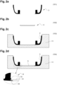
Fig. 2a ] illustre de manière schématique une première étape d'un procédé de fabrication permettant de réaliser un écran de protection selon l'invention ; - [
Fig. 2b ] illustre de manière schématique une deuxième étape d'un procédé de fabrication permettant de réaliser un écran de protection selon l'invention ; - [
Fig. 2c ] illustre de manière schématique une troisième étape d'un procédé de fabrication permettant de réaliser un écran de protection selon l'invention ; - [
Fig. 2d ] illustre de manière schématique une quatrième étape d'un procédé de fabrication permettant de réaliser un écran de protection selon l'invention ; - [
Fig. 2e ] illustre de manière schématique une cinquième étape d'un procédé de fabrication permettant de réaliser un écran de protection selon l'invention ; - [
Fig. 2f ] illustre de manière schématique une sixième étape d'un procédé de fabrication permettant de réaliser un écran de protection selon l'invention ; - [
Fig. 2g ] illustre de manière schématique une septième étape d'un procédé de fabrication permettant de réaliser un écran de protection selon l'invention ; - [
Fig. 2h ] illustre de manière schématique une huitième étape d'un procédé de fabrication permettant de réaliser un écran de protection selon l'invention ; - [
Fig. 3 ] est un diagramme illustrant les variations du gain acoustique (exprimé en dB) en fonction de la fréquence (exprimée en Hz) d'une onde acoustique traversant un écran de protection selon l'invention et, en comparaison, celles obtenues lorsque la même onde acoustique traverse un écran de protection conventionnel. - En référence à la
figure 1 , un écran 1 de protection acoustique est disposé sur un moteur 2 de véhicule automobile et sous un capot (non représenté). L'écran 1 comprend une première partie 3 en matériau plastique, notamment en polyamide, et une deuxième partie 4 en un matériau absorbant acoustique. La première partie 3 recouvre la deuxième partie 4 de manière à la masquer au moins partiellement. Elle possède en outre une ouverture centrale 32 servant de logement à une troisième partie 5, ladite troisième partie 5 étant formée dans un matériau déformable permettant d'absorber efficacement les chocs transmis par le capot du véhicule automobile. Un tel matériau déformable sera un matériau fibreux, de préférence à base de fibres de verre, de masse surfacique comprise entre 400 et 1000 g/m2. - La première partie 3 comprend deux rebords latéraux 31 à profil courbe. Chacun des rebords latéraux 31 comprend un segment principal 311 jouxtant l'ouverture centrale 32 et un premier segment d'extrémité 312 jouxtant le segment principal 311 et orienté perpendiculairement à celui-ci, ledit premier segment d'extrémité 312 formant un bord périphérique de l'écran 1. A son extrémité libre 313, le segment d'extrémité 312 jouxte, sans le toucher, le moteur 2. L'espace séparant le segment principal 311 et le premier segment d'extrémité 312 du moteur 2 est intégralement ou quasi-intégralement occupé par la deuxième partie 4. Chacun des rebords latéraux 31 comprend également un deuxième segment d'extrémité 314 orienté perpendiculairement au segment principal 311, ledit deuxième segment d'extrémité 314 possédant une forme sensiblement cylindrique et s'étendant depuis le segment principal 311 vers le bas en direction du moteur 2. Il traverse de part en part la deuxième partie 4. Son extrémité libre 315 est configurée pour former un logement pour un pion 6 fixé sur le moteur 2, permettant ainsi la fixation de l'écran 1 sur le moteur 2. Dans une configuration particulière de l'invention, ladite extrémité libre 315 recevra un plot creux dans lequel viendra s'emboîter le pion 6. Dans une autre configuration particulière de l'invention, la première partie 3 pourra comprendre au moins une zone d'extrémité destinée à venir recouvrir une partie chaude du moteur 2. Cette zone d'extrémité pourra par exemple former une extension d'un des rebords latéraux 31.
- La deuxième partie 4 présente sur sa face inférieure 41, qui est en contact avec le moteur 2, un profil sensiblement complémentaire à celui de la face supérieure du moteur 2. Elle occupe l'intégralité ou quasiment l'intégralité de l'espace séparant les première et troisième parties 3, 5 du moteur 2. Elle est constituée de préférence d'un matériau en mousse de polyuréthanne de masse volumique comprise entre 70 et 200 kg/m3.
- En référence aux
figures 2a à 2h , les différentes étapes d'un procédé de fabrication d'un écran 1 conforme à celui illustré sur lafigure 1 sont représentées. Ce procédé comprend notamment : - une première étape 101 au cours de laquelle la première partie 3 est formée par injection plastique.
- une deuxième étape 102 au cours de laquelle la troisième partie 5 est formée par thermocompression.
- une troisième étape 103 au cours de laquelle la première partie 3 est transférée dans une matrice inférieure 11 d'un moule.
- une quatrième étape 104 au cours de laquelle la troisième partie 5 est positionnée à l'intérieur de l'ouverture centrale 32 de la première partie 3. Comme représenté sur le détail D, cette étape pourra être facilitée dans le cas où la première partie 3 comporte des ergots 33 saillant au niveau de l'ouverture centrale 32, lesdits ergots 33 étant configurés pour loger les extrémités latérales 51 de la troisième partie 5 de telle sorte à maintenir en position ladite troisième partie 5 à l'intérieur de l'ouverture centrale 32. Dans une variante du procédé, les étapes 103 et 104 pourront être inversées.
- une cinquième étape 105 au cours de laquelle un matériau absorbant acoustique est coulé dans la matrice inférieure 11 du moule de manière à recouvrir la première partie 3 et la troisième partie 5.
- une sixième étape 106 au cours de laquelle le moule est fermé, ledit moule étant formé de la matrice inférieure 11 susmentionnée et d'une matrice supérieure 12 possédant une géométrie complémentaire de celle du moteur 2.
- une septième étape 107 au cours de laquelle le matériau absorbant acoustique subit une expansion, notamment sous l'effet de la chaleur, de telle sorte à remplir totalement l'espace libre à l'intérieur du moule 10. La deuxième partie 4 est ainsi surmoulée sur la première partie 3 et la troisième partie 5.
- une huitième étape 108 au cours de laquelle le moule 10 est ouvert et l'écran 1 ainsi formé est démoulé.
- D'autres étapes additionnelles pourront être prévues. En particulier, l'étape 108 pourra être suivie d'une étape consistant à assembler des plots creux aux extrémités libres 315 des deuxièmes segments d'extrémité 314 et/ou une étape de formation d'un décor sur la face supérieure de l'écran 1.
- Par ailleurs, la sixième étape 106 pourra être remplacée par une étape intermédiaire, effectuée postérieurement à l'étape 107 et préalablement à l'étape 108, au cours de laquelle le matériau absorbant acoustique est injecté dans le moule formé par les matrices inférieure et supérieure 11, 12.
- En référence à la
figure 3 , il est représenté un diagramme montrant les variations du gain acoustique (exprimé en dB) en fonction de la fréquence (exprimée en Hz) d'une onde acoustique traversant un écran de protection selon l'invention (exemple 1) et, en comparaison, celles obtenues lorsque la même onde acoustique traverse un écran de protection conventionnel (exemple comparatif), formé d'un cadre en matière plastique à l'intérieur duquel est emprisonné un matériau absorbant acoustique à base de fibres, tel que décrit par exemple dans la demande debrevet FR 2 979 086
Claims (16)
- Ecran (1) de protection acoustique pour moteur (2) de véhicule automobile comprenant :- une première partie (3) constituée d'un matériau plastique, ladite première partie (3) comportant des moyens de fixation de l'écran (1) sur un moteur (2) de véhicule automobile,- une deuxième partie (4) constituée au moins partiellement d'un matériau absorbant acoustique, ladite deuxième partie (4) étant destinée à venir au contact du moteur (2),dans lequel la première partie (3) recouvre la deuxième partie (4) de manière à la masquer au moins partiellement, caractérisé en ce que la première partie (3) présente une ouverture centrale (32) servant de logement à une troisième partie (5), ladite troisième partie (5) étant formée dans un matériau déformable permettant d'absorber les chocs transmis par le capot du véhicule automobile lors d'un choc piéton, ledit matériau déformable étant un matériau fibreux.
- Ecran (1) selon la revendication 1, caractérisé en ce que la deuxième partie (4) est surmoulée sur la première partie (3) et la troisième partie (5).
- Ecran (1) selon l'une des revendications précédentes, caractérisé en ce que la première partie (3) comprend deux rebords latéraux (31) à profil courbe, chacun des rebords latéraux (31) comprenant un segment principal (311) jouxtant l'ouverture centrale (32) et un premier segment d'extrémité (312) jouxtant le segment principal (311) et orienté perpendiculairement à celui-ci, ledit premier segment d'extrémité (312) formant un bord périphérique de l'écran (1).
- Ecran (1) selon la revendication 3, caractérisé en ce que chacun des rebords latéraux (31) comprend également un deuxième segment d'extrémité (314) orienté perpendiculairement au segment principal (311), ledit deuxième segment d'extrémité (314) étant configuré pour former un logement pour un pion (6) fixé sur le moteur (2), permettant ainsi la fixation de l'écran (1) sur le moteur (2).
- Ecran (1) selon la revendication 4, caractérisé en ce que le deuxième segment d'extrémité (314) possède une forme sensiblement cylindrique.
- Ecran (1) selon l'une des revendications précédentes, caractérisé en ce que la première partie (3) est en matériau polyamide.
- Ecran (1) selon l'une des revendications précédentes, caractérisé en ce que la deuxième partie (4) est à base de mousse de polyuréthanne.
- Ecran (1) selon la revendication 7, caractérisé en ce que la mousse de polyuréthanne possède une masse volumique comprise entre 70 et 200 kg/m3.
- Ecran (1) selon l'une des revendications précédentes, caractérisé en ce que la troisième partie (5) est en fibres de verre.
- Ecran (1) selon l'une des revendications précédentes, caractérisé en ce que le matériau fibreux possède une masse surfacique comprise entre 400 et 1000 g/m2.
- Ecran (1) selon l'une des revendications précédentes, caractérisé en ce que la première partie (3) comporte des ergots (33) saillant au niveau de l'ouverture centrale (32), lesdits ergots (33) étant configurés pour maintenir en position la troisième partie (5) à l'intérieur de l'ouverture centrale (32).
- Ensemble comprenant un moteur (2) pourvu d'un écran (1) selon l'une des revendications précédentes, caractérisé en ce que les moyens de fixation de l'écran (1) coopèrent avec des moyens de fixation complémentaires (6) solidaires du moteur (2) de manière à assurer la fixation dudit écran sur ledit moteur.
- Ensemble selon la revendication 12, caractérisé en ce que les moyens de fixation de l'écran comprennent au moins un plot présentant un logement destiné à recevoir en emboîtement un pion (6) solidaire du moteur.
- Ensemble selon la revendication 12 ou 13, caractérisé en ce qu'une partie chaude du moteur est recouverte par au moins une zone d'extrémité de la première partie (3) de l'écran (1).
- Procédé de fabrication d'un écran (1) de protection acoustique selon l'une des revendications 1 à 11, caractérisé en ce qu'il comprend les étapes suivantes :a) Formation (101) par injection plastique de la première partie (3) ;b) Formation (102) par thermocompression de la troisième partie (5) ;c) Transfert (103) de la première partie (3) dans une matrice inférieure (11) d'un moule ;d) Positionnement (104) de la troisième partie (5) à l'intérieur de l'ouverture centrale (32) de la première partie (3) ;e) Coulée (105) d'un matériau absorbant acoustique dans la matrice inférieure (11) du moule de manière à recouvrir la première partie (3) et la troisième partie (5);f) Fermeture (106) du moule formé de la matrice inférieure (11) susmentionnée et d'une matrice supérieure (12) possédant une géométrie complémentaire de celle de la deuxième partie (4) ;g) Expansion (107) du matériau absorbant acoustique de manière à former la deuxième partie (4) ;h) Démoulage (108) de l'écran (1).
- Procédé selon la revendication 15, caractérisé en ce que l'étape e) est remplacée par une étape f'), succédant à l'étape f) et effectuée préalablement à l'étape g), au cours de laquelle le matériau absorbant acoustique est injecté dans le moule formé par les matrices inférieure et supérieure (11, 12).
Applications Claiming Priority (2)
| Application Number | Priority Date | Filing Date | Title |
|---|---|---|---|
| FR1910293A FR3100770B1 (fr) | 2019-09-18 | 2019-09-18 | Ecran de protection acoustique pour moteur de véhicule automobile |
| PCT/FR2020/051627 WO2021053308A1 (fr) | 2019-09-18 | 2020-09-18 | Ecran de protection acoustique pour moteur de véhicule automobile |
Publications (2)
| Publication Number | Publication Date |
|---|---|
| EP4031417A1 EP4031417A1 (fr) | 2022-07-27 |
| EP4031417B1 true EP4031417B1 (fr) | 2024-01-03 |
Family
ID=69468680
Family Applications (1)
| Application Number | Title | Priority Date | Filing Date |
|---|---|---|---|
| EP20820267.1A Active EP4031417B1 (fr) | 2019-09-18 | 2020-09-18 | Ecran de protection acoustique pour moteur de véhicule automobile |
Country Status (5)
| Country | Link |
|---|---|
| US (1) | US12109952B2 (fr) |
| EP (1) | EP4031417B1 (fr) |
| ES (1) | ES2973735T3 (fr) |
| FR (1) | FR3100770B1 (fr) |
| WO (1) | WO2021053308A1 (fr) |
Citations (1)
| Publication number | Priority date | Publication date | Assignee | Title |
|---|---|---|---|---|
| EP1925511A1 (fr) * | 2006-11-23 | 2008-05-28 | Peugeot Citroën Automobiles S.A. | Ecran de protection pour piéton obtenu par surmoulage |
Family Cites Families (8)
| Publication number | Priority date | Publication date | Assignee | Title |
|---|---|---|---|---|
| US5706908A (en) * | 1994-04-18 | 1998-01-13 | Nissan Motor Co., Ltd. | Front upper structure of automotive vehicle |
| DE10314220C5 (de) * | 2003-03-28 | 2009-09-10 | Woco Industrietechnik Gmbh | Abdeckung für wenigstens eine Komponente in einem Motorraum eines Kraftfahrzeugs |
| DE10317305B4 (de) * | 2003-04-14 | 2006-04-13 | Carcoustics Tech Center Gmbh | Abdeckung für ein Aggregat im Motorraum eines Kraftfahrzeuges |
| DE102006052900A1 (de) * | 2006-11-08 | 2008-05-15 | Polytec Automotive Gmbh & Co. Kg | Motorabdeckung mit Schaum als Fußgängerschutz |
| US20100143661A1 (en) * | 2008-11-18 | 2010-06-10 | Warrick Russell C | Energy Absorption Material |
| FR2979086B1 (fr) | 2011-08-16 | 2017-01-27 | Mecaplast Sa | Ecran acoustique |
| FR3055598B1 (fr) | 2016-09-02 | 2021-06-11 | Cera Aps | Ecran de protection acoustique pour moteur de vehicule automobile |
| US10495024B2 (en) * | 2017-10-05 | 2019-12-03 | Ford Global Technologies, Llc | Reinforced vehicle component cover |
-
2019
- 2019-09-18 FR FR1910293A patent/FR3100770B1/fr not_active Expired - Fee Related
-
2020
- 2020-09-18 EP EP20820267.1A patent/EP4031417B1/fr active Active
- 2020-09-18 WO PCT/FR2020/051627 patent/WO2021053308A1/fr not_active Ceased
- 2020-09-18 US US17/642,006 patent/US12109952B2/en active Active
- 2020-09-18 ES ES20820267T patent/ES2973735T3/es active Active
Patent Citations (1)
| Publication number | Priority date | Publication date | Assignee | Title |
|---|---|---|---|---|
| EP1925511A1 (fr) * | 2006-11-23 | 2008-05-28 | Peugeot Citroën Automobiles S.A. | Ecran de protection pour piéton obtenu par surmoulage |
Also Published As
| Publication number | Publication date |
|---|---|
| EP4031417A1 (fr) | 2022-07-27 |
| FR3100770A1 (fr) | 2021-03-19 |
| FR3100770B1 (fr) | 2021-08-27 |
| US20240042948A1 (en) | 2024-02-08 |
| ES2973735T3 (es) | 2024-06-24 |
| WO2021053308A1 (fr) | 2021-03-25 |
| US12109952B2 (en) | 2024-10-08 |
Similar Documents
| Publication | Publication Date | Title |
|---|---|---|
| EP2114728B1 (fr) | Panneau de protection acoustique pour vehicule automobile comprenant une couche d'etancheite impregnee | |
| EP3442831B1 (fr) | Procédé de réalisation d'un panneau insonorisant de garnissage intérieur de véhicule automobile | |
| EP3271215B1 (fr) | Procédé de réalisation d'un écran de protection acoustique pour moteur de véhicule automobile et écran obtenu par un tel procédé | |
| FR2852901A1 (fr) | Couvercle pour un composant dans un compartiment moteur d'un vehicule automobile et composant d'accouplement pour un couvercle | |
| EP3766715B1 (fr) | Insert de renfort muni d'orifices traversants | |
| WO2010069923A1 (fr) | Pylone central d'aéronef | |
| EP4031417A1 (fr) | Ecran de protection acoustique pour moteur de véhicule automobile | |
| EP3838543B1 (fr) | Procédé de réalisation d'un coussin pour élément de siège de véhicule automobile | |
| EP1527954B1 (fr) | Elément de faux plancher multifonction comprenant des patins en mousse formant ressort d'un système "masse-ressort" | |
| FR2882540A1 (fr) | Dispositif insonorisant multicouche, respectant des contraintes de chocs pietons, pour composant situe dans le compartiment moteur d'un vehicule automobile | |
| EP3898339B1 (fr) | Système de protection acoustique pour pare-boue de véhicule automobile | |
| EP2130746B1 (fr) | Capot de vehicule, dispositif et procede de fabrication par moulage d'un tel capot. | |
| FR2979086A1 (fr) | Ecran acoustique | |
| FR2864922A1 (fr) | Panneau structurel a peaux poreuses | |
| FR2878221A1 (fr) | Planche de bord a amortissement acoustique pour vehicule automobile | |
| EP0128050A2 (fr) | Elément moulé fait de fibres minérales pourvues d'un liant pour recouvrir de manière insonorisante un tuyau d'échappement perforé ainsi qu'un procédé pour sa fabrication | |
| FR2786840A1 (fr) | Revetement automobile a proprietes amortissantes mecaniquement et acoustiquement | |
| FR3015393A1 (fr) | Dispositif de securite pour vehicule | |
| FR2880310A1 (fr) | Perfectionnement aux sieges d'un vehicule automobile | |
| WO2004089698A2 (fr) | Support pour une piece de carrosserie de vehicule automobile | |
| EP2546125B1 (fr) | Ensemble d'une aile et d'une pièce porteuse pour un véhicule automobile de type camion | |
| EP1520770A1 (fr) | Module de plancher structurel présentant des propriétés de protection acoustique | |
| EP1843021A2 (fr) | Cache moteur pour véhicule automobile | |
| FR3164410A1 (fr) | Procédé de fabrication d’un panneau de garnissage de véhicule et panneau de garnissage ainsi obtenu | |
| EP4197774A1 (fr) | Panneau de protection acoustique pour véhicule automobile |
Legal Events
| Date | Code | Title | Description |
|---|---|---|---|
| STAA | Information on the status of an ep patent application or granted ep patent |
Free format text: STATUS: UNKNOWN |
|
| STAA | Information on the status of an ep patent application or granted ep patent |
Free format text: STATUS: THE INTERNATIONAL PUBLICATION HAS BEEN MADE |
|
| PUAI | Public reference made under article 153(3) epc to a published international application that has entered the european phase |
Free format text: ORIGINAL CODE: 0009012 |
|
| STAA | Information on the status of an ep patent application or granted ep patent |
Free format text: STATUS: REQUEST FOR EXAMINATION WAS MADE |
|
| 17P | Request for examination filed |
Effective date: 20220406 |
|
| AK | Designated contracting states |
Kind code of ref document: A1 Designated state(s): AL AT BE BG CH CY CZ DE DK EE ES FI FR GB GR HR HU IE IS IT LI LT LU LV MC MK MT NL NO PL PT RO RS SE SI SK SM TR |
|
| DAV | Request for validation of the european patent (deleted) | ||
| DAX | Request for extension of the european patent (deleted) | ||
| STAA | Information on the status of an ep patent application or granted ep patent |
Free format text: STATUS: EXAMINATION IS IN PROGRESS |
|
| 17Q | First examination report despatched |
Effective date: 20230117 |
|
| P01 | Opt-out of the competence of the unified patent court (upc) registered |
Effective date: 20230526 |
|
| GRAP | Despatch of communication of intention to grant a patent |
Free format text: ORIGINAL CODE: EPIDOSNIGR1 |
|
| STAA | Information on the status of an ep patent application or granted ep patent |
Free format text: STATUS: GRANT OF PATENT IS INTENDED |
|
| INTG | Intention to grant announced |
Effective date: 20230824 |
|
| RAP3 | Party data changed (applicant data changed or rights of an application transferred) |
Owner name: NOVARES FRANCE |
|
| GRAS | Grant fee paid |
Free format text: ORIGINAL CODE: EPIDOSNIGR3 |
|
| GRAA | (expected) grant |
Free format text: ORIGINAL CODE: 0009210 |
|
| STAA | Information on the status of an ep patent application or granted ep patent |
Free format text: STATUS: THE PATENT HAS BEEN GRANTED |
|
| AK | Designated contracting states |
Kind code of ref document: B1 Designated state(s): AL AT BE BG CH CY CZ DE DK EE ES FI FR GB GR HR HU IE IS IT LI LT LU LV MC MK MT NL NO PL PT RO RS SE SI SK SM TR |
|
| REG | Reference to a national code |
Ref country code: GB Ref legal event code: FG4D Free format text: NOT ENGLISH |
|
| REG | Reference to a national code |
Ref country code: DE Ref legal event code: R096 Ref document number: 602020023982 Country of ref document: DE |
|
| REG | Reference to a national code |
Ref country code: CH Ref legal event code: EP |
|
| REG | Reference to a national code |
Ref country code: IE Ref legal event code: FG4D Free format text: LANGUAGE OF EP DOCUMENT: FRENCH |
|
| REG | Reference to a national code |
Ref country code: LT Ref legal event code: MG9D |
|
| REG | Reference to a national code |
Ref country code: NL Ref legal event code: MP Effective date: 20240103 |
|
| REG | Reference to a national code |
Ref country code: AT Ref legal event code: MK05 Ref document number: 1646490 Country of ref document: AT Kind code of ref document: T Effective date: 20240103 |
|
| REG | Reference to a national code |
Ref country code: ES Ref legal event code: FG2A Ref document number: 2973735 Country of ref document: ES Kind code of ref document: T3 Effective date: 20240624 |
|
| PG25 | Lapsed in a contracting state [announced via postgrant information from national office to epo] |
Ref country code: NL Free format text: LAPSE BECAUSE OF FAILURE TO SUBMIT A TRANSLATION OF THE DESCRIPTION OR TO PAY THE FEE WITHIN THE PRESCRIBED TIME-LIMIT Effective date: 20240103 |
|
| PG25 | Lapsed in a contracting state [announced via postgrant information from national office to epo] |
Ref country code: NL Free format text: LAPSE BECAUSE OF FAILURE TO SUBMIT A TRANSLATION OF THE DESCRIPTION OR TO PAY THE FEE WITHIN THE PRESCRIBED TIME-LIMIT Effective date: 20240103 |
|
| PG25 | Lapsed in a contracting state [announced via postgrant information from national office to epo] |
Ref country code: IS Free format text: LAPSE BECAUSE OF FAILURE TO SUBMIT A TRANSLATION OF THE DESCRIPTION OR TO PAY THE FEE WITHIN THE PRESCRIBED TIME-LIMIT Effective date: 20240503 |
|
| PG25 | Lapsed in a contracting state [announced via postgrant information from national office to epo] |
Ref country code: LT Free format text: LAPSE BECAUSE OF FAILURE TO SUBMIT A TRANSLATION OF THE DESCRIPTION OR TO PAY THE FEE WITHIN THE PRESCRIBED TIME-LIMIT Effective date: 20240103 |
|
| PG25 | Lapsed in a contracting state [announced via postgrant information from national office to epo] |
Ref country code: GR Free format text: LAPSE BECAUSE OF FAILURE TO SUBMIT A TRANSLATION OF THE DESCRIPTION OR TO PAY THE FEE WITHIN THE PRESCRIBED TIME-LIMIT Effective date: 20240404 |
|
| PG25 | Lapsed in a contracting state [announced via postgrant information from national office to epo] |
Ref country code: HR Free format text: LAPSE BECAUSE OF FAILURE TO SUBMIT A TRANSLATION OF THE DESCRIPTION OR TO PAY THE FEE WITHIN THE PRESCRIBED TIME-LIMIT Effective date: 20240103 Ref country code: RS Free format text: LAPSE BECAUSE OF FAILURE TO SUBMIT A TRANSLATION OF THE DESCRIPTION OR TO PAY THE FEE WITHIN THE PRESCRIBED TIME-LIMIT Effective date: 20240403 |
|
| PG25 | Lapsed in a contracting state [announced via postgrant information from national office to epo] |
Ref country code: AT Free format text: LAPSE BECAUSE OF FAILURE TO SUBMIT A TRANSLATION OF THE DESCRIPTION OR TO PAY THE FEE WITHIN THE PRESCRIBED TIME-LIMIT Effective date: 20240103 Ref country code: CZ Free format text: LAPSE BECAUSE OF FAILURE TO SUBMIT A TRANSLATION OF THE DESCRIPTION OR TO PAY THE FEE WITHIN THE PRESCRIBED TIME-LIMIT Effective date: 20240103 |
|
| PG25 | Lapsed in a contracting state [announced via postgrant information from national office to epo] |
Ref country code: RS Free format text: LAPSE BECAUSE OF FAILURE TO SUBMIT A TRANSLATION OF THE DESCRIPTION OR TO PAY THE FEE WITHIN THE PRESCRIBED TIME-LIMIT Effective date: 20240403 Ref country code: NO Free format text: LAPSE BECAUSE OF FAILURE TO SUBMIT A TRANSLATION OF THE DESCRIPTION OR TO PAY THE FEE WITHIN THE PRESCRIBED TIME-LIMIT Effective date: 20240403 Ref country code: LT Free format text: LAPSE BECAUSE OF FAILURE TO SUBMIT A TRANSLATION OF THE DESCRIPTION OR TO PAY THE FEE WITHIN THE PRESCRIBED TIME-LIMIT Effective date: 20240103 Ref country code: IS Free format text: LAPSE BECAUSE OF FAILURE TO SUBMIT A TRANSLATION OF THE DESCRIPTION OR TO PAY THE FEE WITHIN THE PRESCRIBED TIME-LIMIT Effective date: 20240503 Ref country code: HR Free format text: LAPSE BECAUSE OF FAILURE TO SUBMIT A TRANSLATION OF THE DESCRIPTION OR TO PAY THE FEE WITHIN THE PRESCRIBED TIME-LIMIT Effective date: 20240103 Ref country code: GR Free format text: LAPSE BECAUSE OF FAILURE TO SUBMIT A TRANSLATION OF THE DESCRIPTION OR TO PAY THE FEE WITHIN THE PRESCRIBED TIME-LIMIT Effective date: 20240404 Ref country code: CZ Free format text: LAPSE BECAUSE OF FAILURE TO SUBMIT A TRANSLATION OF THE DESCRIPTION OR TO PAY THE FEE WITHIN THE PRESCRIBED TIME-LIMIT Effective date: 20240103 Ref country code: BG Free format text: LAPSE BECAUSE OF FAILURE TO SUBMIT A TRANSLATION OF THE DESCRIPTION OR TO PAY THE FEE WITHIN THE PRESCRIBED TIME-LIMIT Effective date: 20240103 Ref country code: AT Free format text: LAPSE BECAUSE OF FAILURE TO SUBMIT A TRANSLATION OF THE DESCRIPTION OR TO PAY THE FEE WITHIN THE PRESCRIBED TIME-LIMIT Effective date: 20240103 |
|
| PG25 | Lapsed in a contracting state [announced via postgrant information from national office to epo] |
Ref country code: PL Free format text: LAPSE BECAUSE OF FAILURE TO SUBMIT A TRANSLATION OF THE DESCRIPTION OR TO PAY THE FEE WITHIN THE PRESCRIBED TIME-LIMIT Effective date: 20240103 Ref country code: PT Free format text: LAPSE BECAUSE OF FAILURE TO SUBMIT A TRANSLATION OF THE DESCRIPTION OR TO PAY THE FEE WITHIN THE PRESCRIBED TIME-LIMIT Effective date: 20240503 |
|
| PG25 | Lapsed in a contracting state [announced via postgrant information from national office to epo] |
Ref country code: SE Free format text: LAPSE BECAUSE OF FAILURE TO SUBMIT A TRANSLATION OF THE DESCRIPTION OR TO PAY THE FEE WITHIN THE PRESCRIBED TIME-LIMIT Effective date: 20240103 Ref country code: PT Free format text: LAPSE BECAUSE OF FAILURE TO SUBMIT A TRANSLATION OF THE DESCRIPTION OR TO PAY THE FEE WITHIN THE PRESCRIBED TIME-LIMIT Effective date: 20240503 Ref country code: PL Free format text: LAPSE BECAUSE OF FAILURE TO SUBMIT A TRANSLATION OF THE DESCRIPTION OR TO PAY THE FEE WITHIN THE PRESCRIBED TIME-LIMIT Effective date: 20240103 Ref country code: LV Free format text: LAPSE BECAUSE OF FAILURE TO SUBMIT A TRANSLATION OF THE DESCRIPTION OR TO PAY THE FEE WITHIN THE PRESCRIBED TIME-LIMIT Effective date: 20240103 |
|
| REG | Reference to a national code |
Ref country code: DE Ref legal event code: R097 Ref document number: 602020023982 Country of ref document: DE |
|
| PG25 | Lapsed in a contracting state [announced via postgrant information from national office to epo] |
Ref country code: DK Free format text: LAPSE BECAUSE OF FAILURE TO SUBMIT A TRANSLATION OF THE DESCRIPTION OR TO PAY THE FEE WITHIN THE PRESCRIBED TIME-LIMIT Effective date: 20240103 |
|
| PG25 | Lapsed in a contracting state [announced via postgrant information from national office to epo] |
Ref country code: SM Free format text: LAPSE BECAUSE OF FAILURE TO SUBMIT A TRANSLATION OF THE DESCRIPTION OR TO PAY THE FEE WITHIN THE PRESCRIBED TIME-LIMIT Effective date: 20240103 |
|
| PG25 | Lapsed in a contracting state [announced via postgrant information from national office to epo] |
Ref country code: EE Free format text: LAPSE BECAUSE OF FAILURE TO SUBMIT A TRANSLATION OF THE DESCRIPTION OR TO PAY THE FEE WITHIN THE PRESCRIBED TIME-LIMIT Effective date: 20240103 |
|
| PG25 | Lapsed in a contracting state [announced via postgrant information from national office to epo] |
Ref country code: SK Free format text: LAPSE BECAUSE OF FAILURE TO SUBMIT A TRANSLATION OF THE DESCRIPTION OR TO PAY THE FEE WITHIN THE PRESCRIBED TIME-LIMIT Effective date: 20240103 |
|
| PG25 | Lapsed in a contracting state [announced via postgrant information from national office to epo] |
Ref country code: SM Free format text: LAPSE BECAUSE OF FAILURE TO SUBMIT A TRANSLATION OF THE DESCRIPTION OR TO PAY THE FEE WITHIN THE PRESCRIBED TIME-LIMIT Effective date: 20240103 Ref country code: SK Free format text: LAPSE BECAUSE OF FAILURE TO SUBMIT A TRANSLATION OF THE DESCRIPTION OR TO PAY THE FEE WITHIN THE PRESCRIBED TIME-LIMIT Effective date: 20240103 Ref country code: RO Free format text: LAPSE BECAUSE OF FAILURE TO SUBMIT A TRANSLATION OF THE DESCRIPTION OR TO PAY THE FEE WITHIN THE PRESCRIBED TIME-LIMIT Effective date: 20240103 Ref country code: EE Free format text: LAPSE BECAUSE OF FAILURE TO SUBMIT A TRANSLATION OF THE DESCRIPTION OR TO PAY THE FEE WITHIN THE PRESCRIBED TIME-LIMIT Effective date: 20240103 Ref country code: DK Free format text: LAPSE BECAUSE OF FAILURE TO SUBMIT A TRANSLATION OF THE DESCRIPTION OR TO PAY THE FEE WITHIN THE PRESCRIBED TIME-LIMIT Effective date: 20240103 |
|
| PLBE | No opposition filed within time limit |
Free format text: ORIGINAL CODE: 0009261 |
|
| STAA | Information on the status of an ep patent application or granted ep patent |
Free format text: STATUS: NO OPPOSITION FILED WITHIN TIME LIMIT |
|
| PG25 | Lapsed in a contracting state [announced via postgrant information from national office to epo] |
Ref country code: IT Free format text: LAPSE BECAUSE OF FAILURE TO SUBMIT A TRANSLATION OF THE DESCRIPTION OR TO PAY THE FEE WITHIN THE PRESCRIBED TIME-LIMIT Effective date: 20240103 |
|
| 26N | No opposition filed |
Effective date: 20241007 |
|
| PG25 | Lapsed in a contracting state [announced via postgrant information from national office to epo] |
Ref country code: IT Free format text: LAPSE BECAUSE OF FAILURE TO SUBMIT A TRANSLATION OF THE DESCRIPTION OR TO PAY THE FEE WITHIN THE PRESCRIBED TIME-LIMIT Effective date: 20240103 |
|
| PGFP | Annual fee paid to national office [announced via postgrant information from national office to epo] |
Ref country code: ES Payment date: 20241217 Year of fee payment: 5 |
|
| PG25 | Lapsed in a contracting state [announced via postgrant information from national office to epo] |
Ref country code: SI Free format text: LAPSE BECAUSE OF FAILURE TO SUBMIT A TRANSLATION OF THE DESCRIPTION OR TO PAY THE FEE WITHIN THE PRESCRIBED TIME-LIMIT Effective date: 20240103 Ref country code: MC Free format text: LAPSE BECAUSE OF FAILURE TO SUBMIT A TRANSLATION OF THE DESCRIPTION OR TO PAY THE FEE WITHIN THE PRESCRIBED TIME-LIMIT Effective date: 20240103 |
|
| REG | Reference to a national code |
Ref country code: CH Ref legal event code: PL |
|
| PG25 | Lapsed in a contracting state [announced via postgrant information from national office to epo] |
Ref country code: LU Free format text: LAPSE BECAUSE OF NON-PAYMENT OF DUE FEES Effective date: 20240918 |
|
| GBPC | Gb: european patent ceased through non-payment of renewal fee |
Effective date: 20240918 |
|
| PG25 | Lapsed in a contracting state [announced via postgrant information from national office to epo] |
Ref country code: GB Free format text: LAPSE BECAUSE OF NON-PAYMENT OF DUE FEES Effective date: 20240918 |
|
| REG | Reference to a national code |
Ref country code: BE Ref legal event code: MM Effective date: 20240930 |
|
| PG25 | Lapsed in a contracting state [announced via postgrant information from national office to epo] |
Ref country code: BE Free format text: LAPSE BECAUSE OF NON-PAYMENT OF DUE FEES Effective date: 20240930 |
|
| PG25 | Lapsed in a contracting state [announced via postgrant information from national office to epo] |
Ref country code: CH Free format text: LAPSE BECAUSE OF NON-PAYMENT OF DUE FEES Effective date: 20240930 |
|
| PG25 | Lapsed in a contracting state [announced via postgrant information from national office to epo] |
Ref country code: IE Free format text: LAPSE BECAUSE OF NON-PAYMENT OF DUE FEES Effective date: 20240918 |
|
| PG25 | Lapsed in a contracting state [announced via postgrant information from national office to epo] |
Ref country code: FI Free format text: LAPSE BECAUSE OF FAILURE TO SUBMIT A TRANSLATION OF THE DESCRIPTION OR TO PAY THE FEE WITHIN THE PRESCRIBED TIME-LIMIT Effective date: 20240103 |
|
| PGFP | Annual fee paid to national office [announced via postgrant information from national office to epo] |
Ref country code: FR Payment date: 20250731 Year of fee payment: 6 |
|
| PGFP | Annual fee paid to national office [announced via postgrant information from national office to epo] |
Ref country code: DE Payment date: 20251029 Year of fee payment: 6 |
|
| PG25 | Lapsed in a contracting state [announced via postgrant information from national office to epo] |
Ref country code: CY Free format text: LAPSE BECAUSE OF FAILURE TO SUBMIT A TRANSLATION OF THE DESCRIPTION OR TO PAY THE FEE WITHIN THE PRESCRIBED TIME-LIMIT; INVALID AB INITIO Effective date: 20200918 |
|
| PG25 | Lapsed in a contracting state [announced via postgrant information from national office to epo] |
Ref country code: HU Free format text: LAPSE BECAUSE OF FAILURE TO SUBMIT A TRANSLATION OF THE DESCRIPTION OR TO PAY THE FEE WITHIN THE PRESCRIBED TIME-LIMIT; INVALID AB INITIO Effective date: 20200918 |