EP4031273B1 - Rotation mixer with improved belt drive - Google Patents
Rotation mixer with improved belt drive Download PDFInfo
- Publication number
- EP4031273B1 EP4031273B1 EP20866849.1A EP20866849A EP4031273B1 EP 4031273 B1 EP4031273 B1 EP 4031273B1 EP 20866849 A EP20866849 A EP 20866849A EP 4031273 B1 EP4031273 B1 EP 4031273B1
- Authority
- EP
- European Patent Office
- Prior art keywords
- arm
- pulleys
- axis
- coupled
- belt
- Prior art date
- Legal status (The legal status is an assumption and is not a legal conclusion. Google has not performed a legal analysis and makes no representation as to the accuracy of the status listed.)
- Active
Links
Images



Classifications
-
- B—PERFORMING OPERATIONS; TRANSPORTING
- B01—PHYSICAL OR CHEMICAL PROCESSES OR APPARATUS IN GENERAL
- B01F—MIXING, e.g. DISSOLVING, EMULSIFYING OR DISPERSING
- B01F29/00—Mixers with rotating receptacles
- B01F29/40—Parts or components, e.g. receptacles, feeding or discharging means
-
- B—PERFORMING OPERATIONS; TRANSPORTING
- B01—PHYSICAL OR CHEMICAL PROCESSES OR APPARATUS IN GENERAL
- B01F—MIXING, e.g. DISSOLVING, EMULSIFYING OR DISPERSING
- B01F29/00—Mixers with rotating receptacles
- B01F29/10—Mixers with rotating receptacles with receptacles rotated about two different axes, e.g. receptacles having planetary motion
-
- B—PERFORMING OPERATIONS; TRANSPORTING
- B01—PHYSICAL OR CHEMICAL PROCESSES OR APPARATUS IN GENERAL
- B01F—MIXING, e.g. DISSOLVING, EMULSIFYING OR DISPERSING
- B01F29/00—Mixers with rotating receptacles
- B01F29/60—Mixers with rotating receptacles rotating about a horizontal or inclined axis, e.g. drum mixers
- B01F29/62—Mixers with rotating receptacles rotating about a horizontal or inclined axis, e.g. drum mixers without bars, i.e. without mixing elements; characterised by the shape or cross section of the receptacle, e.g. of Y-, Z-, S- or X- shape; with cylindrical receptacles rotating about an axis at an angle to their longitudinal axis
-
- B—PERFORMING OPERATIONS; TRANSPORTING
- B01—PHYSICAL OR CHEMICAL PROCESSES OR APPARATUS IN GENERAL
- B01F—MIXING, e.g. DISSOLVING, EMULSIFYING OR DISPERSING
- B01F35/00—Accessories for mixers; Auxiliary operations or auxiliary devices; Parts or details of general application
- B01F35/40—Mounting or supporting mixing devices or receptacles; Clamping or holding arrangements therefor
- B01F35/42—Clamping or holding arrangements for mounting receptacles on mixing devices
- B01F35/421—Clamping or holding arrangements for mounting receptacles on mixing devices having a cup-shaped or cage-type form
-
- F—MECHANICAL ENGINEERING; LIGHTING; HEATING; WEAPONS; BLASTING
- F16—ENGINEERING ELEMENTS AND UNITS; GENERAL MEASURES FOR PRODUCING AND MAINTAINING EFFECTIVE FUNCTIONING OF MACHINES OR INSTALLATIONS; THERMAL INSULATION IN GENERAL
- F16H—GEARING
- F16H7/00—Gearings for conveying rotary motion by endless flexible members
- F16H7/02—Gearings for conveying rotary motion by endless flexible members with belts; with V-belts
- F16H7/023—Gearings for conveying rotary motion by endless flexible members with belts; with V-belts with belts having a toothed contact surface or regularly spaced bosses or hollows for slipless or nearly slipless meshing with complementary profiled contact surface of a pulley
-
- F—MECHANICAL ENGINEERING; LIGHTING; HEATING; WEAPONS; BLASTING
- F16—ENGINEERING ELEMENTS AND UNITS; GENERAL MEASURES FOR PRODUCING AND MAINTAINING EFFECTIVE FUNCTIONING OF MACHINES OR INSTALLATIONS; THERMAL INSULATION IN GENERAL
- F16H—GEARING
- F16H7/00—Gearings for conveying rotary motion by endless flexible members
- F16H7/08—Means for varying tension of belts, ropes or chains
- F16H7/10—Means for varying tension of belts, ropes or chains by adjusting the axis of a pulley
- F16H7/12—Means for varying tension of belts, ropes or chains by adjusting the axis of a pulley of an idle pulley
- F16H7/1254—Means for varying tension of belts, ropes or chains by adjusting the axis of a pulley of an idle pulley without vibration damping means
- F16H7/1263—Means for varying tension of belts, ropes or chains by adjusting the axis of a pulley of an idle pulley without vibration damping means where the axis of the pulley moves along a substantially straight path
-
- B—PERFORMING OPERATIONS; TRANSPORTING
- B01—PHYSICAL OR CHEMICAL PROCESSES OR APPARATUS IN GENERAL
- B01F—MIXING, e.g. DISSOLVING, EMULSIFYING OR DISPERSING
- B01F29/00—Mixers with rotating receptacles
- B01F29/40—Parts or components, e.g. receptacles, feeding or discharging means
- B01F29/403—Disposition of the rotor axis
- B01F29/4035—Disposition of the rotor axis with a receptacle rotating around two or more axes
- B01F29/40351—Disposition of the rotor axis with a receptacle rotating around two or more axes having different, non-perpendicular inclinations, e.g. skew axes
-
- F—MECHANICAL ENGINEERING; LIGHTING; HEATING; WEAPONS; BLASTING
- F16—ENGINEERING ELEMENTS AND UNITS; GENERAL MEASURES FOR PRODUCING AND MAINTAINING EFFECTIVE FUNCTIONING OF MACHINES OR INSTALLATIONS; THERMAL INSULATION IN GENERAL
- F16H—GEARING
- F16H7/00—Gearings for conveying rotary motion by endless flexible members
- F16H7/08—Means for varying tension of belts, ropes or chains
- F16H2007/0876—Control or adjustment of actuators
- F16H2007/088—Manual adjustment
Definitions
- the present invention relates generally to devices and methods of mixing. More specifically, the present invention relates to devices and methods for mixing fluids, semi-fluids, gels, particles, powders, and other flowable material.
- Dynamic mixing such as rotation mixing
- Rotational mixers can include a rotation and/or or oscillation component to assist in mixing the substances.
- Dual Asymmetric Centrifugal (DAC) mixing can be particularly fast and effective by imposing centrifugal (centripetal) force in multiple directions on the substance(s) to be mixed.
- Various containers can be selected for containing the substance(s) to be mixed and undergoing the DAC rotation.
- EP2258467 A1 describes a method and device for mixing liquid, flowable or powdery materials, in particular for mixing automobile repair varnishes for use in spray guns.
- the device has a rotary arm rotatably mounted on a frame.
- a drive device is provided for a rotary drive of the rotary arm and a rotary drive of a mixture receptacle.
- US 2011/315785 A1 describes a device for mixing fluid, and powdered, flowable materials, particularly for mixing automotive refinish coatings for use with spray guns, having a first component mounted rotatably on a frame, having a second component bearing or forming a mixing product receptacle mounted rotatably on the first component and having at least one drive device for a rotary drive of the first component and a rotary drive of the mixing product receptacle.
- US 6,709,151 B2 describes a mixing device for mixing liquid, flowable or powdery materials comprising a pivoted first component, with a second component pivoted on the first component, with a drive mechanism for generating a rotational movement of the first component.
- a rotation mixer may include a housing, a drive unit coupled to the housing, a carriage mounted on the drive unit for rotation relative to the housing, and a basket mounted for rotation relative to the carriage.
- the basket may receive material to be mixed.
- the carriage may include an arm and a drive line coupled to the arm.
- the arm may be mounted on the drive unit for rotation about a first axis relative to the housing, and the drive line may convert rotation of the arm into rotation of the basket about a second axis relative to the arm during use of the rotation mixer.
- the second axis may be arranged at an oblique angle relative to the first axis.
- the drive line may include a belt and a plurality of pulleys coupled to the arm.
- the belt may be routed around the pulleys and engage with a ring gear coupled to the basket and a transfer gear coupled to the housing.
- the transfer gear may be fixed against rotation about the first axis.
- the arm may include opposite first and second ends and a support body extending between the first and second ends.
- the basket may be mounted to the first end and the support body may be mounted to the drive unit.
- a counterweight may be coupled to the second end.
- a bore may extend into the support body to receive a shaft of the drive unit.
- the plurality of pulleys may include six pulleys. Four pulleys may be coupled adjacent to the bore, and two of the pulleys may be coupled adjacent to the second end.
- a tensioner may be coupled to the arm and arranged to adjust a tension in the belt.
- the tensioner may include a frame coupled to the arm and an adjustment mechanism coupled between the arm and the frame for selective movement of the frame relative to the arm.
- Two pulleys of the plurality of pulleys may be coupled to the frame for movement with the frame relative to the arm.
- a rotation mixer 100 includes a housing 102, a drive unit 104 coupled to housing 102, a carriage 10 (sometimes referred to as an arm) mounted on drive unit 104 for rotation relative to housing 102, and a basket 106 mounted for rotation relative to carriage 10 as shown in Figs. 1-3 .
- basket 106 is shaped and designed to receive a holder 101 with a material container 103 as shown in Fig. 1 .
- basket 106 receives material container 103 directly as shown in Figs. 2 and 3 .
- a material to be mixed 99 is received in material container 103 as shown in Fig. 6 .
- rotation mixer 100 is arranged as a Dual Asymmetric Centrifugal (DAC) rotation mixer.
- DAC Dual Asymmetric Centrifugal
- Carriage 10 in accordance with the present invention includes an arm 12 and a drive line 14 coupled to arm 12 as shown in Figs. 2 and 3 .
- Carriage 10 is mounted on drive unit 104, such as an electric motor, for rotation about a first axis A in a rotational direction (indicated by arrow 200) relative to housing 102 during use of rotation mixer 100.
- Basket 106 is arranged for rotation about a second axis B in a rotational direction (indicated by arrow 202) during use of rotation mixer 100.
- Axis B is arranged at an oblique angle relative to axis A.
- a transfer gear 108 is coupled to housing 102 and fixed against rotation about axis A.
- Drive line 14 engages with transfer gear 108 and a ring gear 109 coupled to basket 106 to convert rotation of arm 12 about axis A into rotation of basket 106 about axis B.
- carriage 10 and basket 106 rotate in opposite rotational directions 200 and 202 around their respective axes A, B.
- carriage 10 rotates counter-clockwise around axis A while basket 106 rotates clockwise around axis B.
- rotational mixers can be found within U.S. Patent Nos. 6,099,160 and 6,755,565 .
- Such dual axis rotation mixing including asymmetric rotation may be referred to as planetary mixing and/or centrifugal mixing, although these terms may not be entirely accurate and are not intended to limit mixing parameters such as the direction of rotation about each of the dual axes, speed, and/or other geometry relationships.
- Arm 12 includes a first end 22, a second end 24 spaced apart from first end 22, and a support body 20 extending between first and second ends 22, 24 as shown in Figs. 2-4 .
- Basket 106 is coupled to first end 22 and arranged for rotation relative to arm 12.
- basket 106 can be coupled to a spindle 52 engaged with one or more bearings 54 mounted in first end 22 to support basket 106 on arm 12 while allowing rotation about axis B as shown in Figs. 6 and 7 .
- one or more counterweights 26 are coupled to second end 24 of arm 12 to balance carriage 10.
- counterweights 26 can be arranged to align a center of gravity of carriage 10 along axis A.
- a shaft 105 of drive unit 104 engages with support body 20 of arm 12 and a fastener 107, such as a bolt, engages with arm 12 and shaft 105 to hold arm 12 on drive unit 104 as suggested in Figs. 2 and 3 .
- Arm 12 is shown separated from shaft 105 in Fig. 2 and mounted on shaft 105 in Fig. 3 .
- a bore 28 is formed into support body 20 and sized to receive at least a portion of shaft 105 therein as shown in Figs. 4-6 .
- a press fit is formed between shaft 105 and bore 28.
- a key 21 engages with arm 12 and shaft 105 to block rotation of shaft 105 relative to arm 12.
- fastener 107 is narrower than bore 28 (as seen in Figs. 5 and 6 ) and extends through bore 28 to engage with shaft 105.
- bore 28 is threaded to receive a removal tool having a threaded end to engage with the threads of bore 28 and force arm 12 off of shaft 105.
- Drive line 14 includes a belt 30 and a plurality of pulleys 31, 32, 33, 34, 35, 36 coupled to arm 12 as shown in Figs. 2-5 .
- Belt 30 is formed as a continuous loop along a length direction L ( Fig. 4 ) and routed around pulleys 31-36, transfer gear 108, and ring gear 109.
- belt 30 is formed to define ribs or teeth for engaging with corresponding ribs or teeth on gears 108, 109.
- Pulleys 31-36 guide belt 30 between transfer gear 108 and ring gear 109.
- the plurality of pulleys 31, 32, 33, 34, 35, 36 includes a pair of first pulleys 31, 36 coupled to support body 20, a pair of second pulleys 32, 35 coupled to second end 24, and a pair of third pulleys 33, 34 coupled to first end 22 as shown in Fig. 4 .
- Belt 30 extends from ring gear 109 (coupled to basket 106) to first pulleys 31, 36, extends from first pulleys 31, 36 to second pulleys 32, 35, extends from second pulleys 32, 35 to third pulleys 33, 34, and extends from third pulleys 33, 34 to transfer gear 108 (coupled with housing 102).
- First pulleys 31, 36 are arranged substantially perpendicular to axis A, and second pulleys 32, 35 and third pulleys 33, 34 are arranged substantially parallel to axis A.
- Belt 30 flexes and twists between various orientations during movement along pulleys 31-36 and gears 108, 109.
- belt 30 twists across a width direction W ( Fig. 4 ) of belt 30 from a substantially vertical orientation at ring gear 109 (e.g., width direction W arranged substantially parallel to axis B) to a substantially horizontal orientation at pulley 31 (e.g., width direction W arranged substantially perpendicular to axis A and/or axis B) and back to a substantially vertical orientation at pulley 32 (e.g., width direction W arranged substantially parallel to axis A).
- Pulley 31 is spaced apart from ring gear 109, and pulley 32 is spaced apart from pulley 31, to allow belt 30 to twist along a substantial distance, such as from adjacent first end 22 of arm 12 to adjacent bore 28 and from adjacent bore 28 to adjacent second end 24. These distances are longer than in other devices, such as the one found within U.S. Patent No. 6,709,151 , the disclosure of which is incorporated by reference herein in its entirety.
- the arrangement of pulleys 31, 32, 35, 36 relative to ring gear 109 also limit an amount of twist on belt 30.
- belt 30 twists about 90 degrees or less from the orientation on ring gear 109 to the orientation on pulley 31.
- Belt 30 then twists back 90 degrees from the orientation on pulley 31 to the orientation on pulley 32, resulting in a total twist on belt 30 of about 90 degrees from ring gear 109 to pulley 32 as compared to about 180 degrees of total twist on belts used in other devices. Twisting of belt 30 by more than 90 degrees but less than 180 degrees is also contemplated by the present invention.
- An overall length of belt 30 is also longer than belts in other devices, further reducing wear on belt 30, as contact points with the pulleys or turns and twists on any point along belt 30 occur less often as the belt 30 travels through the pulley system.
- first end 22 of arm 12 and basket 106 also allows first end 22 of arm 12 and basket 106 to be arranged closer to drive unit 104 relative to second end 24, thereby moving a center of gravity of carriage 10 closer to drive unit 104 compared to other devices.
- First end 22 of the arm 12 can further be lowered closer to drive unit 104 in the housing 102, thereby permitting basket 106 to sit lower in the housing 102, reducing gravitational forces acting on the basket 106 during the mixing process.
- a tensioner 40 is coupled to arm 12 and configured for adjusting a tension along belt 30 as shown in Figs. 2-5 .
- Tensioner 40 allows adjustment of tension in belt 30 to levels sufficient for efficient operation of drive line 14 while minimizing stress on pulleys 31-36.
- Tensioner 40 includes a frame 42 coupled to second end 24 of arm 12 and an adjustment mechanism 44 coupled between arm 12 and frame 42 for selective movement of frame 42 relative to arm 12.
- Pulleys 32, 35 are mounted to frame 42 for movement with frame 42 relative to arm 12.
- adjustment mechanism 44 includes a threaded fastener 46, such as a bolt, engaged with arm 12 and extending into a threaded hole 48 of frame 42 to drive movement of frame 42 with rotation of fastener 46.
- fasteners 41 extend through slots 43 of frame 42 to hold frame 42 on arm 12 and allow sliding movement of frame 42 relative to arm 12 as shown in Figs. 4-7 .
- fasteners engage with caps 45 to couple fasteners 41 with arm 12.
- a cover plate 50 is coupled to arm 12 to block access to drive line 14 during operation of rotational mixer 100.
- a weight of frame 42 allows smaller counterweights 26 to be used compared to other devices.
- Tensioner 40 can illustratively act as a counter mass to the basket 106 on arm 12 during rotation of arm 12 about axis A.
- Substances or formulations that can be mixed in rotation mixer 100 include, but are not limited to, fluids, semi-fluids, suspensions, colloids, gels, pastes, articles, granules, powders, other flowable material, and mixtures or combinations of at least two of the foregoing.
- materials that can be mixed include, but are not limited to, creams, epoxies, inks, adhesives, sealants, and coatings.
Landscapes
- Engineering & Computer Science (AREA)
- General Engineering & Computer Science (AREA)
- Chemical & Material Sciences (AREA)
- Chemical Kinetics & Catalysis (AREA)
- Mechanical Engineering (AREA)
- Mixers With Rotating Receptacles And Mixers With Vibration Mechanisms (AREA)
- Accessories For Mixers (AREA)
Description
- The present invention relates generally to devices and methods of mixing. More specifically, the present invention relates to devices and methods for mixing fluids, semi-fluids, gels, particles, powders, and other flowable material.
- Dynamic mixing, such as rotation mixing, can provide effective, non-invasive mixing of substances or formulations, and without mixer components extending into the substance, such as stirring rods. Rotational mixers can include a rotation and/or or oscillation component to assist in mixing the substances. Dual Asymmetric Centrifugal (DAC) mixing can be particularly fast and effective by imposing centrifugal (centripetal) force in multiple directions on the substance(s) to be mixed. Various containers can be selected for containing the substance(s) to be mixed and undergoing the DAC rotation.
-
EP2258467 A1 describes a method and device for mixing liquid, flowable or powdery materials, in particular for mixing automobile repair varnishes for use in spray guns. The device has a rotary arm rotatably mounted on a frame. A drive device is provided for a rotary drive of the rotary arm and a rotary drive of a mixture receptacle.US 2011/315785 A1 describes a device for mixing fluid, and powdered, flowable materials, particularly for mixing automotive refinish coatings for use with spray guns, having a first component mounted rotatably on a frame, having a second component bearing or forming a mixing product receptacle mounted rotatably on the first component and having at least one drive device for a rotary drive of the first component and a rotary drive of the mixing product receptacle.US 6,709,151 B2 describes a mixing device for mixing liquid, flowable or powdery materials comprising a pivoted first component, with a second component pivoted on the first component, with a drive mechanism for generating a rotational movement of the first component. - According to an aspect of the present invention, a rotation mixer may include a housing, a drive unit coupled to the housing, a carriage mounted on the drive unit for rotation relative to the housing, and a basket mounted for rotation relative to the carriage. The basket may receive material to be mixed. The carriage may include an arm and a drive line coupled to the arm. The arm may be mounted on the drive unit for rotation about a first axis relative to the housing, and the drive line may convert rotation of the arm into rotation of the basket about a second axis relative to the arm during use of the rotation mixer. The second axis may be arranged at an oblique angle relative to the first axis.
- In illustrative embodiments, the drive line may include a belt and a plurality of pulleys coupled to the arm. The belt may be routed around the pulleys and engage with a ring gear coupled to the basket and a transfer gear coupled to the housing. The transfer gear may be fixed against rotation about the first axis.
- In illustrative embodiments, the arm may include opposite first and second ends and a support body extending between the first and second ends. The basket may be mounted to the first end and the support body may be mounted to the drive unit. A counterweight may be coupled to the second end. A bore may extend into the support body to receive a shaft of the drive unit.
- In illustrative embodiments, the plurality of pulleys may include six pulleys. Four pulleys may be coupled adjacent to the bore, and two of the pulleys may be coupled adjacent to the second end.
- In illustrative embodiments, a tensioner may be coupled to the arm and arranged to adjust a tension in the belt. The tensioner may include a frame coupled to the arm and an adjustment mechanism coupled between the arm and the frame for selective movement of the frame relative to the arm. Two pulleys of the plurality of pulleys may be coupled to the frame for movement with the frame relative to the arm.
- The drawings disclose exemplary embodiments in which like reference characters designate the same or similar parts throughout the figures of which:
-
Fig. 1 is a perspective view of a rotation mixer in accordance with the present invention. -
Fig. 2 is an exploded assembly view showing a carriage of the rotation mixer separated from a drive unit. -
Fig. 3 is a side elevation view of showing the carriage mounted on the drive unit. -
Fig. 4 is a lower perspective view of the carriage ofFig. 2 . -
Fig. 5 is a bottom plan view of the carriage ofFig. 4 . -
Fig. 6 is a sectional view taken along line 6-6 inFig. 5 . -
Fig. 7 is an exploded assembly view of the carriage ofFig. 2 . -
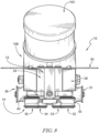
Fig. 8 is a rear elevation view of the carriage ofFig. 2 . -
Fig. 9 is a front elevation view of the carriage ofFig. 2 . -
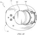
Fig. 10 is a top plan view of the carriage ofFig. 2 . - Unless otherwise indicated, the drawings are intended to be read (for example, cross-hatching, arrangement of parts, proportion, degree, or the like) together with the specification, and are to be considered a portion of the entire written description of this invention. As used in the following description, the terms "horizontal", "vertical", "left", "right", "up" and "down", "upper" and "lower" as well as adjectival and adverbial derivatives thereof (for example, "horizontally", "upwardly", or the like), simply refer to the orientation of the illustrated structure as the particular drawing figure faces the reader. Similarly, the terms "inwardly" and "outwardly" generally refer to the orientation of a surface relative to its axis of elongation, or axis of rotation, as appropriate
- For the purposes of promoting an understanding of the principles of the invention, reference will now be made to a number of illustrative embodiments illustrated in the drawings and specific language will be used to describe the same.
- In the illustrative embodiment, a
rotation mixer 100 includes ahousing 102, adrive unit 104 coupled tohousing 102, a carriage 10 (sometimes referred to as an arm) mounted ondrive unit 104 for rotation relative tohousing 102, and abasket 106 mounted for rotation relative tocarriage 10 as shown inFigs. 1-3 . In some embodiments,basket 106 is shaped and designed to receive aholder 101 with amaterial container 103 as shown inFig. 1 . In some embodiments,basket 106 receivesmaterial container 103 directly as shown inFigs. 2 and3 . A material to be mixed 99 is received inmaterial container 103 as shown inFig. 6 . In some embodiments,rotation mixer 100 is arranged as a Dual Asymmetric Centrifugal (DAC) rotation mixer. -
Carriage 10 in accordance with the present invention includes anarm 12 and adrive line 14 coupled toarm 12 as shown inFigs. 2 and3 .Carriage 10 is mounted ondrive unit 104, such as an electric motor, for rotation about a first axis A in a rotational direction (indicated by arrow 200) relative tohousing 102 during use ofrotation mixer 100.Basket 106 is arranged for rotation about a second axis B in a rotational direction (indicated by arrow 202) during use ofrotation mixer 100. Axis B is arranged at an oblique angle relative to axis A. Atransfer gear 108 is coupled tohousing 102 and fixed against rotation about axisA. Drive line 14 engages withtransfer gear 108 and aring gear 109 coupled tobasket 106 to convert rotation ofarm 12 about axis A into rotation ofbasket 106 about axis B. In the illustrative embodiment,carriage 10 andbasket 106 rotate in oppositerotational directions Fig. 1 ,carriage 10 rotates counter-clockwise around axis A whilebasket 106 rotates clockwise around axis B. - Examples of some rotational mixers can be found within
U.S. Patent Nos. 6,099,160 and6,755,565 . Such dual axis rotation mixing including asymmetric rotation may be referred to as planetary mixing and/or centrifugal mixing, although these terms may not be entirely accurate and are not intended to limit mixing parameters such as the direction of rotation about each of the dual axes, speed, and/or other geometry relationships. -
Arm 12 includes afirst end 22, asecond end 24 spaced apart fromfirst end 22, and asupport body 20 extending between first andsecond ends Figs. 2-4 .Basket 106 is coupled tofirst end 22 and arranged for rotation relative toarm 12. For example,basket 106 can be coupled to aspindle 52 engaged with one ormore bearings 54 mounted infirst end 22 to supportbasket 106 onarm 12 while allowing rotation about axis B as shown inFigs. 6 and7 . In some embodiments, one ormore counterweights 26 are coupled tosecond end 24 ofarm 12 to balancecarriage 10. For example,counterweights 26 can be arranged to align a center of gravity ofcarriage 10 along axis A. - A
shaft 105 ofdrive unit 104 engages withsupport body 20 ofarm 12 and afastener 107, such as a bolt, engages witharm 12 andshaft 105 to holdarm 12 ondrive unit 104 as suggested inFigs. 2 and3 .Arm 12 is shown separated fromshaft 105 inFig. 2 and mounted onshaft 105 inFig. 3 . In the illustrative embodiment, abore 28 is formed intosupport body 20 and sized to receive at least a portion ofshaft 105 therein as shown inFigs. 4-6 . In some embodiments, a press fit is formed betweenshaft 105 and bore 28. In some embodiments, a key 21 engages witharm 12 andshaft 105 to block rotation ofshaft 105 relative toarm 12. In some embodiments, at least a portion offastener 107 is narrower than bore 28 (as seen inFigs. 5 and6 ) and extends throughbore 28 to engage withshaft 105. In some embodiments, bore 28 is threaded to receive a removal tool having a threaded end to engage with the threads ofbore 28 andforce arm 12 off ofshaft 105. - Drive
line 14 includes abelt 30 and a plurality ofpulleys arm 12 as shown inFigs. 2-5 .Belt 30 is formed as a continuous loop along a length direction L (Fig. 4 ) and routed around pulleys 31-36,transfer gear 108, andring gear 109. In some embodiments,belt 30 is formed to define ribs or teeth for engaging with corresponding ribs or teeth ongears guide belt 30 betweentransfer gear 108 andring gear 109. In the illustrative embodiment, the plurality ofpulleys first pulleys body 20, a pair ofsecond pulleys second end 24, and a pair ofthird pulleys first end 22 as shown inFig. 4 .Belt 30 extends from ring gear 109 (coupled to basket 106) tofirst pulleys first pulleys second pulleys second pulleys third pulleys third pulleys second pulleys third pulleys -
Belt 30 flexes and twists between various orientations during movement along pulleys 31-36 and gears 108, 109. For example, from the perspective ofFigs. 2 and3 ,belt 30 twists across a width direction W (Fig. 4 ) ofbelt 30 from a substantially vertical orientation at ring gear 109 (e.g., width direction W arranged substantially parallel to axis B) to a substantially horizontal orientation at pulley 31 (e.g., width direction W arranged substantially perpendicular to axis A and/or axis B) and back to a substantially vertical orientation at pulley 32 (e.g., width direction W arranged substantially parallel to axis A).Pulley 31 is spaced apart fromring gear 109, andpulley 32 is spaced apart frompulley 31, to allowbelt 30 to twist along a substantial distance, such as from adjacentfirst end 22 ofarm 12 toadjacent bore 28 and fromadjacent bore 28 to adjacentsecond end 24. These distances are longer than in other devices, such as the one found withinU.S. Patent No. 6,709,151 , the disclosure of which is incorporated by reference herein in its entirety. - The arrangement of
pulleys gear 109 also limit an amount of twist onbelt 30. For example, belt 30 twists about 90 degrees or less from the orientation onring gear 109 to the orientation onpulley 31.Belt 30 then twists back 90 degrees from the orientation onpulley 31 to the orientation onpulley 32, resulting in a total twist onbelt 30 of about 90 degrees fromring gear 109 topulley 32 as compared to about 180 degrees of total twist on belts used in other devices. Twisting ofbelt 30 by more than 90 degrees but less than 180 degrees is also contemplated by the present invention. - The arrangement of
drive line 14, including the spacing and orientation of pulleys 31-36, limits wear onbelt 30. The use of six pulleys 31-36 indrive line 14, as compared to four pulleys used in other devices, further limits wear onbelt 30 and limits stresses experienced at each pulley 31-36. An overall length ofbelt 30 is also longer than belts in other devices, further reducing wear onbelt 30, as contact points with the pulleys or turns and twists on any point alongbelt 30 occur less often as thebelt 30 travels through the pulley system. Arrangement of pulleys 31-36 and subsequently routing ofbelt 30 on pulleys 31-36 also allowsfirst end 22 ofarm 12 andbasket 106 to be arranged closer to driveunit 104 relative tosecond end 24, thereby moving a center of gravity ofcarriage 10 closer to driveunit 104 compared to other devices. First end 22 of thearm 12 can further be lowered closer to driveunit 104 in thehousing 102, thereby permittingbasket 106 to sit lower in thehousing 102, reducing gravitational forces acting on thebasket 106 during the mixing process. These advantages that can provide for a reduction of materials, cost and complexity of thecarriage 10 and/or an increase in durability of thecarriage 10. - In the illustrative embodiment, a
tensioner 40 is coupled toarm 12 and configured for adjusting a tension alongbelt 30 as shown inFigs. 2-5 .Tensioner 40 allows adjustment of tension inbelt 30 to levels sufficient for efficient operation ofdrive line 14 while minimizing stress on pulleys 31-36.Tensioner 40 includes aframe 42 coupled tosecond end 24 ofarm 12 and anadjustment mechanism 44 coupled betweenarm 12 andframe 42 for selective movement offrame 42 relative toarm 12.Pulleys frame 42 relative toarm 12. In some embodiments,adjustment mechanism 44 includes a threadedfastener 46, such as a bolt, engaged witharm 12 and extending into a threadedhole 48 offrame 42 to drive movement offrame 42 with rotation offastener 46. In some embodiments,fasteners 41 extend throughslots 43 offrame 42 to holdframe 42 onarm 12 and allow sliding movement offrame 42 relative toarm 12 as shown inFigs. 4-7 . In some embodiments, fasteners engage withcaps 45 to couplefasteners 41 witharm 12. Acover plate 50 is coupled toarm 12 to block access to driveline 14 during operation ofrotational mixer 100. In some embodiments, a weight offrame 42 allowssmaller counterweights 26 to be used compared to other devices.Tensioner 40 can illustratively act as a counter mass to thebasket 106 onarm 12 during rotation ofarm 12 about axis A. - Additional views of
carriage 10 can be seen inFigs. 8-10 . - Substances or formulations that can be mixed in
rotation mixer 100 include, but are not limited to, fluids, semi-fluids, suspensions, colloids, gels, pastes, articles, granules, powders, other flowable material, and mixtures or combinations of at least two of the foregoing. Examples of materials that can be mixed include, but are not limited to, creams, epoxies, inks, adhesives, sealants, and coatings. - The variations and benefits of each embodiment described herein are equally applicable to the other embodiments described herein, and any combinations therebetween are fully contemplated by this disclosure.
Claims (8)
- A carriage (10) arranged for rotation about a first axis (A) in a rotation mixer (100), the carriage (10) comprising:an arm (12) including a first end (22), a second end (24) spaced apart from first end (22), and a support body (20) extending between the first and second ends (22, 24);a drive line (14) including a plurality of pulleys (31, 32, 33, 34, 35, 36) coupled to the arm (12) and a belt (30) routed around the pulleys, anda basket (106) mounted on the first end (22) of the arm (12) for rotation relative to the arm (12) about a second axis (B) arranged at an oblique angle relative to the first axis (A),wherein the belt (30) is formed as a continuous loop along a length direction (L) of the belt (30), the belt (30) is coupled to the basket (106) such that rotation of the arm (12) about the first axis (A) drives rotation of the basket (106) about the second axis (B), and the plurality of pulleys (31, 32, 33, 34, 35, 36) are arranged such that the belt (30) twists across a width direction (W) of the belt (30) less than about 90 degrees throughout the drive line (14), and characterized in that the plurality of pulleys (31, 32, 33, 34, 35, 36) includes a pair of first pulleys (31, 36) coupled to the support body (20) of the arm (12), a pair of second pulleys (32, 35) coupled to the second end (24) of the arm (12), and a pair of third pulleys (33, 34) coupled to the first end (22) of the arm (12).
- The carriage (10) of claim 1, wherein the belt (30) extends from the basket (106) to the first pulleys (31, 36), extends from the first pulleys (31, 36) to the second pulleys (32, 35), extends from the second pulleys (32, 35) to the third pulleys (33, 34), and extends from the third pulleys (33, 34) toward the second end (24) of the arm (12).
- The carriage (10) of claim 2, wherein the first pulleys (31, 36) are arranged substantially perpendicular to the first axis (A), and wherein the second pulleys (32, 35) and the third pulleys (33, 34) are arranged substantially parallel to the first axis (A).
- The carriage (10) of claim 2, further comprising a tensioner (40) including a frame (42) coupled to the second end (24) of the arm (12) and an adjustment mechanism (44) coupled between the arm (12) and the frame (42) for selective movement of the frame (42) relative to the arm (12), wherein the second pulleys (32, 35) are coupled to the frame (42) for movement with the frame (42) relative to the arm (12).
- The carriage (10) of claim 4, further comprising a fastener (41) extending through a slot (43) of the frame (42) and engaging with the arm (12) to hold the frame (42) on the arm (12) and allow sliding movement of the frame (42) relative to the arm (12).
- The carriage (10) of claim 4, wherein the adjustment mechanism (44) includes a threaded fastener (46) extending through a portion of the arm (12) and engaged with the frame (42) such that rotation of the threaded fastener (46) drives movement of the frame (42) relative to the arm (12).
- The carriage (10) of claim 1, wherein the width direction (W) of the belt (30) is substantially parallel to the second axis (B) adjacent to the basket (106), substantially perpendicular to at least one of the first and second axes (A, B) adjacent to the support body (20) of the arm (12), and substantially parallel to the first axis (A) adjacent to the second end (24) of the arm (12).
- The carriage (10) of claim 1, further comprising a ring gear (109) coupled to the basket (106) for rotation with the basket (106) about the second axis (B) and a transfer gear (108) coupled to the housing (102), wherein the transfer gear (108) is fixed against rotation about the first axis (A), and wherein the belt (30) engages with the ring gear (109) and the transfer gear (108).
Applications Claiming Priority (2)
| Application Number | Priority Date | Filing Date | Title |
|---|---|---|---|
| US201962902860P | 2019-09-19 | 2019-09-19 | |
| PCT/US2020/051830 WO2021055957A1 (en) | 2019-09-19 | 2020-09-21 | Rotation mixer with improved belt drive |
Publications (3)
| Publication Number | Publication Date |
|---|---|
| EP4031273A1 EP4031273A1 (en) | 2022-07-27 |
| EP4031273A4 EP4031273A4 (en) | 2023-08-02 |
| EP4031273B1 true EP4031273B1 (en) | 2025-01-29 |
Family
ID=74880422
Family Applications (1)
| Application Number | Title | Priority Date | Filing Date |
|---|---|---|---|
| EP20866849.1A Active EP4031273B1 (en) | 2019-09-19 | 2020-09-21 | Rotation mixer with improved belt drive |
Country Status (4)
| Country | Link |
|---|---|
| US (2) | US11633704B2 (en) |
| EP (1) | EP4031273B1 (en) |
| ES (1) | ES3023209T3 (en) |
| WO (1) | WO2021055957A1 (en) |
Families Citing this family (7)
| Publication number | Priority date | Publication date | Assignee | Title |
|---|---|---|---|---|
| US9724657B2 (en) * | 2013-10-22 | 2017-08-08 | Tyme, Inc. | High-speed centrifugal mixing devices and methods of use |
| JP6903327B2 (en) * | 2017-02-22 | 2021-07-14 | 株式会社写真化学 | Rotational motion transmission device |
| WO2019014259A1 (en) | 2017-07-10 | 2019-01-17 | Liftwave, Inc. Dba Rise Robotics | Normalizing tension distribution and minimizing sidewall abrasion within angular drive belt systems |
| ES3023209T3 (en) * | 2019-09-19 | 2025-05-30 | Flacktek Inc | Rotation mixer with improved belt drive |
| EP4366861A4 (en) * | 2021-07-09 | 2025-05-14 | Flacktek Speedmixer, Inc. | Hub with interchangeable arms for a mixer and interchangeable mixing system |
| EP4387762A4 (en) * | 2021-08-17 | 2025-07-09 | Flacktek Speedmixer Inc | Compact centrifugal mixing device and method of using the same |
| US20250235875A1 (en) * | 2022-04-05 | 2025-07-24 | 11559010 Canada Inc. | Grinding adapter for a dual asymmetric centrifugal mixer and method of use thereof |
Family Cites Families (19)
| Publication number | Priority date | Publication date | Assignee | Title |
|---|---|---|---|---|
| US3679184A (en) * | 1969-01-14 | 1972-07-25 | Woodham Cecil H | Mixing devices |
| US4084493A (en) * | 1977-02-14 | 1978-04-18 | Elias Dennis Quintana | Apparatus for producing foodstuff products |
| US4586292A (en) * | 1985-01-30 | 1986-05-06 | The United States Of America As Represented By The United States Department Of Energy | Machine imparting complex rotary motion for lapping a spherical inner diameter |
| JPS63310629A (en) | 1987-06-12 | 1988-12-19 | Katsuto Araki | Rotary kneader |
| DE4239284A1 (en) * | 1992-11-23 | 1994-05-26 | Hilti Ag | Mixing device for flowable masses |
| US6099160A (en) | 1999-03-23 | 2000-08-08 | Flacktek, Inc. | Mixing system for mixing and dispensing reactive materials |
| JP4084493B2 (en) * | 1999-03-25 | 2008-04-30 | 株式会社シンキー | Stirring deaerator |
| DE10143439A1 (en) | 2001-09-05 | 2003-03-20 | Hauschild & Co Kg | Mixing device for mixing liquid, flowable or powdery materials |
| US6755565B2 (en) | 2002-04-17 | 2004-06-29 | Flacktek, Inc. | Deep holder for dual asymmetric centrifugal mixing system |
| US20060154765A1 (en) * | 2005-01-10 | 2006-07-13 | Wen-Hao Wang | Transmission device for an agitator of impression material |
| US7507015B2 (en) * | 2006-02-14 | 2009-03-24 | Shu-Lung Wang | Mixer for dental molding powder |
| DE102006025643A1 (en) * | 2006-05-24 | 2007-11-29 | Hauschild & Co Kg | Mixing device with vacuum box |
| EP2258467B1 (en) | 2009-06-04 | 2014-03-19 | Collomix Rühr-und Mischgeräte GmbH | Method and device for mixing liquid, flowable or powdery materials, in particular for mixing automobile repair varnishes for use in spray guns |
| US8617453B2 (en) | 2010-04-20 | 2013-12-31 | Kaga Sangyo Co., Ltd. | Molding method and mold therefor |
| US20110315785A1 (en) * | 2010-06-29 | 2011-12-29 | Alexander Essing | Mixing device for flowable materials |
| US9907319B2 (en) | 2015-03-13 | 2018-03-06 | Steak 'n Shake Enterprises, Inc. | Dual-axis rotational mixer for food products |
| KR102451890B1 (en) * | 2017-10-24 | 2022-10-06 | 현대자동차 주식회사 | Triple pulley auto tensioner and engine provided with the same |
| JP6785011B2 (en) * | 2019-03-30 | 2020-11-18 | 株式会社写真化学 | Stirring / defoaming device |
| ES3023209T3 (en) * | 2019-09-19 | 2025-05-30 | Flacktek Inc | Rotation mixer with improved belt drive |
-
2020
- 2020-09-21 ES ES20866849T patent/ES3023209T3/en active Active
- 2020-09-21 EP EP20866849.1A patent/EP4031273B1/en active Active
- 2020-09-21 WO PCT/US2020/051830 patent/WO2021055957A1/en not_active Ceased
- 2020-09-21 US US17/027,454 patent/US11633704B2/en active Active
-
2023
- 2023-03-28 US US18/127,241 patent/US11872534B2/en active Active
Also Published As
| Publication number | Publication date |
|---|---|
| US20210086148A1 (en) | 2021-03-25 |
| US20230234007A1 (en) | 2023-07-27 |
| US11633704B2 (en) | 2023-04-25 |
| EP4031273A1 (en) | 2022-07-27 |
| WO2021055957A1 (en) | 2021-03-25 |
| EP4031273A4 (en) | 2023-08-02 |
| ES3023209T3 (en) | 2025-05-30 |
| US11872534B2 (en) | 2024-01-16 |
Similar Documents
| Publication | Publication Date | Title |
|---|---|---|
| US11872534B2 (en) | Rotation mixer with continuous belt drive | |
| EP1525914B1 (en) | Gyroscopic mixer for mixing the content of a closed container | |
| EP0599783B1 (en) | Mixing apparatus for flowable material | |
| US4497581A (en) | Paint shaker | |
| US4235553A (en) | Material mixer | |
| EP0617998A1 (en) | An agitator for mixing or blending various products, in particular paints, varnishes or the like | |
| EP0794831B1 (en) | Mixing device | |
| KR102611520B1 (en) | Multi-Shaft Planetary Mixer For Preventing Agglomeration | |
| EP2210655A1 (en) | Churning deaerator | |
| JP4291913B2 (en) | Mixing and stirring device | |
| JPH1043568A (en) | Kneading device | |
| CN107530658A (en) | Mixers for Fluid Products | |
| CN117794649A (en) | Planetary grinder | |
| KR20110114419A (en) | Container used for stirring defoaming apparatus, and stirring defoaming apparatus | |
| DE102020127239B4 (en) | Planetary mill with cooling | |
| DE102020127240B4 (en) | Planetary mill with inclined planetary axis | |
| KR20230039271A (en) | Multiaxis type apparatus for mixing | |
| CN208975222U (en) | Public rotating gear transmission component and stirring Defoaming machine | |
| KR19980018239A (en) | Kneading device | |
| US3054600A (en) | Fluid mixing apparatus | |
| JPH1043566A (en) | Kneading device | |
| CN208809938U (en) | Blender is used in a kind of LED production | |
| JP2013202482A (en) | Centrifuge, fluctuation component superimposing mechanism used in the same, and treatment method | |
| CN209034156U (en) | A kind of intensive mixer with double pillar constructions | |
| CN211586287U (en) | Non-contact stirring device |
Legal Events
| Date | Code | Title | Description |
|---|---|---|---|
| STAA | Information on the status of an ep patent application or granted ep patent |
Free format text: STATUS: THE INTERNATIONAL PUBLICATION HAS BEEN MADE |
|
| TPAC | Observations filed by third parties |
Free format text: ORIGINAL CODE: EPIDOSNTIPA |
|
| PUAI | Public reference made under article 153(3) epc to a published international application that has entered the european phase |
Free format text: ORIGINAL CODE: 0009012 |
|
| STAA | Information on the status of an ep patent application or granted ep patent |
Free format text: STATUS: REQUEST FOR EXAMINATION WAS MADE |
|
| 17P | Request for examination filed |
Effective date: 20220329 |
|
| AK | Designated contracting states |
Kind code of ref document: A1 Designated state(s): AL AT BE BG CH CY CZ DE DK EE ES FI FR GB GR HR HU IE IS IT LI LT LU LV MC MK MT NL NO PL PT RO RS SE SI SK SM TR |
|
| DAV | Request for validation of the european patent (deleted) | ||
| DAX | Request for extension of the european patent (deleted) | ||
| REG | Reference to a national code |
Ref country code: DE Ref legal event code: R079 Free format text: PREVIOUS MAIN CLASS: B01F0009020000 Ipc: B01F0029100000 Ref country code: DE Ref legal event code: R079 Ref document number: 602020045626 Country of ref document: DE Free format text: PREVIOUS MAIN CLASS: B01F0009020000 Ipc: B01F0029100000 |
|
| A4 | Supplementary search report drawn up and despatched |
Effective date: 20230629 |
|
| RIC1 | Information provided on ipc code assigned before grant |
Ipc: B01F 29/10 20220101AFI20230623BHEP |
|
| GRAP | Despatch of communication of intention to grant a patent |
Free format text: ORIGINAL CODE: EPIDOSNIGR1 |
|
| STAA | Information on the status of an ep patent application or granted ep patent |
Free format text: STATUS: GRANT OF PATENT IS INTENDED |
|
| RIC1 | Information provided on ipc code assigned before grant |
Ipc: B01F 29/10 20220101AFI20240322BHEP |
|
| INTG | Intention to grant announced |
Effective date: 20240419 |
|
| GRAJ | Information related to disapproval of communication of intention to grant by the applicant or resumption of examination proceedings by the epo deleted |
Free format text: ORIGINAL CODE: EPIDOSDIGR1 |
|
| STAA | Information on the status of an ep patent application or granted ep patent |
Free format text: STATUS: REQUEST FOR EXAMINATION WAS MADE |
|
| INTC | Intention to grant announced (deleted) | ||
| GRAP | Despatch of communication of intention to grant a patent |
Free format text: ORIGINAL CODE: EPIDOSNIGR1 |
|
| STAA | Information on the status of an ep patent application or granted ep patent |
Free format text: STATUS: GRANT OF PATENT IS INTENDED |
|
| P01 | Opt-out of the competence of the unified patent court (upc) registered |
Free format text: CASE NUMBER: APP_44748/2024 Effective date: 20240801 |
|
| INTG | Intention to grant announced |
Effective date: 20240829 |
|
| GRAS | Grant fee paid |
Free format text: ORIGINAL CODE: EPIDOSNIGR3 |
|
| GRAA | (expected) grant |
Free format text: ORIGINAL CODE: 0009210 |
|
| STAA | Information on the status of an ep patent application or granted ep patent |
Free format text: STATUS: THE PATENT HAS BEEN GRANTED |
|
| AK | Designated contracting states |
Kind code of ref document: B1 Designated state(s): AL AT BE BG CH CY CZ DE DK EE ES FI FR GB GR HR HU IE IS IT LI LT LU LV MC MK MT NL NO PL PT RO RS SE SI SK SM TR |
|
| REG | Reference to a national code |
Ref country code: GB Ref legal event code: FG4D |
|
| REG | Reference to a national code |
Ref country code: CH Ref legal event code: EP |
|
| REG | Reference to a national code |
Ref country code: DE Ref legal event code: R096 Ref document number: 602020045626 Country of ref document: DE |
|
| REG | Reference to a national code |
Ref country code: IE Ref legal event code: FG4D Ref country code: NL Ref legal event code: FP |
|
| REG | Reference to a national code |
Ref country code: ES Ref legal event code: FG2A Ref document number: 3023209 Country of ref document: ES Kind code of ref document: T3 Effective date: 20250530 |
|
| PG25 | Lapsed in a contracting state [announced via postgrant information from national office to epo] |
Ref country code: RS Free format text: LAPSE BECAUSE OF FAILURE TO SUBMIT A TRANSLATION OF THE DESCRIPTION OR TO PAY THE FEE WITHIN THE PRESCRIBED TIME-LIMIT Effective date: 20250429 |
|
| PG25 | Lapsed in a contracting state [announced via postgrant information from national office to epo] |
Ref country code: FI Free format text: LAPSE BECAUSE OF FAILURE TO SUBMIT A TRANSLATION OF THE DESCRIPTION OR TO PAY THE FEE WITHIN THE PRESCRIBED TIME-LIMIT Effective date: 20250129 |
|
| PG25 | Lapsed in a contracting state [announced via postgrant information from national office to epo] |
Ref country code: PL Free format text: LAPSE BECAUSE OF FAILURE TO SUBMIT A TRANSLATION OF THE DESCRIPTION OR TO PAY THE FEE WITHIN THE PRESCRIBED TIME-LIMIT Effective date: 20250129 |
|
| REG | Reference to a national code |
Ref country code: LT Ref legal event code: MG9D |
|
| PG25 | Lapsed in a contracting state [announced via postgrant information from national office to epo] |
Ref country code: IS Free format text: LAPSE BECAUSE OF FAILURE TO SUBMIT A TRANSLATION OF THE DESCRIPTION OR TO PAY THE FEE WITHIN THE PRESCRIBED TIME-LIMIT Effective date: 20250529 Ref country code: NO Free format text: LAPSE BECAUSE OF FAILURE TO SUBMIT A TRANSLATION OF THE DESCRIPTION OR TO PAY THE FEE WITHIN THE PRESCRIBED TIME-LIMIT Effective date: 20250429 |
|
| REG | Reference to a national code |
Ref country code: AT Ref legal event code: MK05 Ref document number: 1762907 Country of ref document: AT Kind code of ref document: T Effective date: 20250129 |
|
| PG25 | Lapsed in a contracting state [announced via postgrant information from national office to epo] |
Ref country code: HR Free format text: LAPSE BECAUSE OF FAILURE TO SUBMIT A TRANSLATION OF THE DESCRIPTION OR TO PAY THE FEE WITHIN THE PRESCRIBED TIME-LIMIT Effective date: 20250129 |
|
| PG25 | Lapsed in a contracting state [announced via postgrant information from national office to epo] |
Ref country code: LV Free format text: LAPSE BECAUSE OF FAILURE TO SUBMIT A TRANSLATION OF THE DESCRIPTION OR TO PAY THE FEE WITHIN THE PRESCRIBED TIME-LIMIT Effective date: 20250129 Ref country code: PT Free format text: LAPSE BECAUSE OF FAILURE TO SUBMIT A TRANSLATION OF THE DESCRIPTION OR TO PAY THE FEE WITHIN THE PRESCRIBED TIME-LIMIT Effective date: 20250529 |
|
| PG25 | Lapsed in a contracting state [announced via postgrant information from national office to epo] |
Ref country code: BG Free format text: LAPSE BECAUSE OF FAILURE TO SUBMIT A TRANSLATION OF THE DESCRIPTION OR TO PAY THE FEE WITHIN THE PRESCRIBED TIME-LIMIT Effective date: 20250129 Ref country code: GR Free format text: LAPSE BECAUSE OF FAILURE TO SUBMIT A TRANSLATION OF THE DESCRIPTION OR TO PAY THE FEE WITHIN THE PRESCRIBED TIME-LIMIT Effective date: 20250430 |
|
| PG25 | Lapsed in a contracting state [announced via postgrant information from national office to epo] |
Ref country code: AT Free format text: LAPSE BECAUSE OF FAILURE TO SUBMIT A TRANSLATION OF THE DESCRIPTION OR TO PAY THE FEE WITHIN THE PRESCRIBED TIME-LIMIT Effective date: 20250129 |
|
| PG25 | Lapsed in a contracting state [announced via postgrant information from national office to epo] |
Ref country code: SE Free format text: LAPSE BECAUSE OF FAILURE TO SUBMIT A TRANSLATION OF THE DESCRIPTION OR TO PAY THE FEE WITHIN THE PRESCRIBED TIME-LIMIT Effective date: 20250129 |
|
| PG25 | Lapsed in a contracting state [announced via postgrant information from national office to epo] |
Ref country code: SM Free format text: LAPSE BECAUSE OF FAILURE TO SUBMIT A TRANSLATION OF THE DESCRIPTION OR TO PAY THE FEE WITHIN THE PRESCRIBED TIME-LIMIT Effective date: 20250129 |
|
| PG25 | Lapsed in a contracting state [announced via postgrant information from national office to epo] |
Ref country code: DK Free format text: LAPSE BECAUSE OF FAILURE TO SUBMIT A TRANSLATION OF THE DESCRIPTION OR TO PAY THE FEE WITHIN THE PRESCRIBED TIME-LIMIT Effective date: 20250129 |
|
| PGFP | Annual fee paid to national office [announced via postgrant information from national office to epo] |
Ref country code: DE Payment date: 20250922 Year of fee payment: 6 |
|
| PGFP | Annual fee paid to national office [announced via postgrant information from national office to epo] |
Ref country code: NL Payment date: 20250922 Year of fee payment: 6 Ref country code: IT Payment date: 20250916 Year of fee payment: 6 |
|
| PGFP | Annual fee paid to national office [announced via postgrant information from national office to epo] |
Ref country code: GB Payment date: 20250923 Year of fee payment: 6 |
|
| PGFP | Annual fee paid to national office [announced via postgrant information from national office to epo] |
Ref country code: FR Payment date: 20250912 Year of fee payment: 6 |
|
| PG25 | Lapsed in a contracting state [announced via postgrant information from national office to epo] |
Ref country code: CZ Free format text: LAPSE BECAUSE OF FAILURE TO SUBMIT A TRANSLATION OF THE DESCRIPTION OR TO PAY THE FEE WITHIN THE PRESCRIBED TIME-LIMIT Effective date: 20250129 Ref country code: EE Free format text: LAPSE BECAUSE OF FAILURE TO SUBMIT A TRANSLATION OF THE DESCRIPTION OR TO PAY THE FEE WITHIN THE PRESCRIBED TIME-LIMIT Effective date: 20250129 |
|
| PG25 | Lapsed in a contracting state [announced via postgrant information from national office to epo] |
Ref country code: RO Free format text: LAPSE BECAUSE OF FAILURE TO SUBMIT A TRANSLATION OF THE DESCRIPTION OR TO PAY THE FEE WITHIN THE PRESCRIBED TIME-LIMIT Effective date: 20250129 |
|
| PG25 | Lapsed in a contracting state [announced via postgrant information from national office to epo] |
Ref country code: SK Free format text: LAPSE BECAUSE OF FAILURE TO SUBMIT A TRANSLATION OF THE DESCRIPTION OR TO PAY THE FEE WITHIN THE PRESCRIBED TIME-LIMIT Effective date: 20250129 |
|
| REG | Reference to a national code |
Ref country code: DE Ref legal event code: R097 Ref document number: 602020045626 Country of ref document: DE |
|
| PLBE | No opposition filed within time limit |
Free format text: ORIGINAL CODE: 0009261 |
|
| STAA | Information on the status of an ep patent application or granted ep patent |
Free format text: STATUS: NO OPPOSITION FILED WITHIN TIME LIMIT |
|
| REG | Reference to a national code |
Ref country code: CH Ref legal event code: L10 Free format text: ST27 STATUS EVENT CODE: U-0-0-L10-L00 (AS PROVIDED BY THE NATIONAL OFFICE) Effective date: 20251210 |
|
| 26N | No opposition filed |
Effective date: 20251030 |
|
| PGFP | Annual fee paid to national office [announced via postgrant information from national office to epo] |
Ref country code: ES Payment date: 20251007 Year of fee payment: 6 |
|
| REG | Reference to a national code |
Ref country code: CH Ref legal event code: H13 Free format text: ST27 STATUS EVENT CODE: U-0-0-H10-H13 (AS PROVIDED BY THE NATIONAL OFFICE) Effective date: 20260504 |