EP4031061B1 - Dental floss dispenser - Google Patents
Dental floss dispenser Download PDFInfo
- Publication number
- EP4031061B1 EP4031061B1 EP20865764.3A EP20865764A EP4031061B1 EP 4031061 B1 EP4031061 B1 EP 4031061B1 EP 20865764 A EP20865764 A EP 20865764A EP 4031061 B1 EP4031061 B1 EP 4031061B1
- Authority
- EP
- European Patent Office
- Prior art keywords
- dental floss
- dispensing
- housing
- dispenser
- dispensing portion
- Prior art date
- Legal status (The legal status is an assumption and is not a legal conclusion. Google has not performed a legal analysis and makes no representation as to the accuracy of the status listed.)
- Active
Links
Images







Classifications
-
- A—HUMAN NECESSITIES
- A61—MEDICAL OR VETERINARY SCIENCE; HYGIENE
- A61C—DENTISTRY; APPARATUS OR METHODS FOR ORAL OR DENTAL HYGIENE
- A61C15/00—Devices for cleaning between the teeth
- A61C15/04—Dental floss; Floss holders
- A61C15/043—Containers, dispensers, or the like, e.g. with cutting means
Definitions
- the current subject-matter refers to a dental floss dispenser.
- US 2007/209953 A1 discloses a dental floss dispenser, comprising:a dispenser housing enclosing an interior portion; anda dispensing portion slidably positioned inside the interior portion of the dispenser housing, the dispensing portion having a stored position and a dispensing position, wherein, in the stored position, the dispensing portion is entirely disposed in the interior portion, and, in the dispensing position, the dispensing portion is partially disposed outside of the interior portion;the dispensing portion including a storage chamber for storing a wound string of dental floss and a floss dispensing cavity for holding at least a portion of the wound string of dental floss extracted from the storage chamber; and a locking mechanism configured to temporarily retain the dispensing portion in stored position or the dispensing position wherein the locking mechanism including a latching component, wherein the latching component, upon locking, is configured to retain the dispensing portion in the stored position.
- Dental floss typically comes in a string form and is generally dispensed from a bobbin contained within a dispenser housing. A cutting device is used to cut a desired length of dental floss string. A user can then use the cut length of floss string to insert it between the teeth for flossing.
- Other variations of dental floss appliances include pre-fabricated picks having a short piece of floss spanning across two supports. These picks generally come in packs and are single use items. Once used, the entire pick and used floss are discarded. There is a need to provide a more efficient and effective way of storing and dispensing of dental floss.
- the current subject-matter refers to a dental floss dispenser.
- the dispenser may include a dispenser housing having an interior portion and a dispensing portion slidably disposed inside the interior portion of the dispenser housing.
- a wound string of dental floss may be disposed within a dental floss housing portion.
- the dental floss housing portion may be removably coupled to the dispensing portion.
- the dispenser may further include a locking mechanism configured to temporarily retain the dispensing portion and the dental floss housing portion in the interior portion of the dispenser housing.
- a portion of the wound string of dental floss may be configured to protrude through one or more openings in the dispensing portion.
- the current subject matter relates to a method for loading the dental floss dispenser.
- a user may push on a top of the dispensing portion and remove an interlocked assembly of the dispensing portion and the dental floss housing from the interior portion of the dispenser housing.
- a spring (along with optional damper ring) may be retained inside the dispenser housing. Alternatively, the spring (and/or the damper ring) may be removed. The user may then disengage the floss housing from the dispensing portion. If previous dental floss (or any remains of the wound dental floss) is present in the dental floss housing, the user may remove it (e.g., the dental floss may be retracted from the openings in the dispensing portion by pulling on it).
- a new wound length of dental floss may be positioned inside the dental floss housing. Then, a laminated end of the new wound length of dental floss may be protruded through openings in the dispensing portion, thereby extending it from the top of the dispensing portion.
- the dental floss housing may then be interlocked with the dispensing portion creating the interlocked assembly.
- the interlocked assembly may then be inserted into the interior portion of the dispenser housing (if spring and/or damper ring were previously removed from the interior portion, the damper ring is positioned first on the base and following by the spring). The user may then push the interlocked assembly further into the interior portion of the dispenser housing until a first latch portion and a second latch portion of the locking mechanism engage.
- the user may push on its top portion, thereby causing disengagement of the first and second latch portions and ejecting/partially removing the dispensing assembly from the interior portion.
- a desired length of string of dental floss may be pulled a concave cavity of the dispensing portion and protruded through one or more openings in the dispensing portion to allow cutting the dental floss using one or more cutting blades.
- the user may push on the top portion to secure the dispensing portion in the interior portion.
- the dental floss dispenser may further include a locking mechanism configured to temporarily retain the dispensing portion in stored position or the dispensing position.
- the locking mechanism may include a spring component and a latching component.
- the spring component upon unlocking of the latching component, may be configured to position the dispensing portion in the dispensing position.
- the latching component upon locking, may be configured to retain the dispensing portion in the stored position.
- the wound string of dental floss may be configured to be wound in at least one of the following shapes: a cylinder, a tube, a roll, a torus, a sphere, a cone, a prism, an ellipsoid, a helix, and any combination thereof.
- the dispensing portion may include a concave open cavity having a top and a bottom, a first opening disposed in the bottom and configured for protruding the portion of the wound string of dental floss from the storage chamber, and a second opening disposed in the top and configured for holding the protruded portion of the wound string of dental floss.
- the second opening of the concave open cavity may include a cutting mechanism for cutting the dental floss.
- the storage chamber may be configured to be interlocked with the floss dispensing cavity for holding the wound string of dental floss.
- the current subject matter relates to a method of loading the dental floss dispenser described above.
- the method may include providing the dental floss dispenser, as described above, removing the dispensing portion from the interior portion of the dispenser housing, inserting the wound string of dental floss into the storage chamber, extracting at least a portion of the wound string of dental floss from the storage chamber and positioning the extracted portion of the wound string of dental floss across the floss dispensing cavity, and placing the dispensing portion into the interior portion of the dispenser housing.
- the current subject matter relates to a method of using the dental floss dispenser described above.
- the method may include providing the dental floss dispenser, as described above, partially removing the dispensing portion from the interior portion of the dispenser housing, extracting at least a portion of dental floss from the storage chamber and securing the extracted portion to the floss dispensing cavity, using the dental floss dispenser for flossing, and placing the dispensing portion into the interior portion of the dispenser housing.
- the housing 102 may have any other shape, e.g., cube, parallelogram, and/or any other desired shape.
- the bottom portion 106 may be configured to have a circular shape and may be coupled to the housing 102 by any desired means (e.g., glued, welded, detachably attached, forming a unitary structure with the housing 102, etc.).
- the dispensing portion 108 may be configured to be ejected/removed/partially removed from the top portion 104 of the housing 102.
- the dispensing portion 108 may be ejected/removed/partially removed using a spring and/or a latch mechanisms disposed in the interior portion 112 of the housing 102 (not shown in FIGS 1a-2b ).
- the dispensing portion 108 may be ejected/removed/partially removed from the top portion 104 of the housing 102 by application of a downward force on and subsequent release of the top of the dispensing portion 108, thereby allowing the dispensing portion 108 to "pop out" from the interior portion 112 of the housing 102 (as shown in FIGS. 3a-c ).
- the dispensing portion 108 may be returned to the interior portion 112 of the housing 102 by application of the downward force on the top of the dispensing portion 108 and pushing the dispensing portion 108 into the interior portion 112 until the dispensing portion 108 is locked inside the interior portion 112 using a locking mechanism (not shown in FIGS. 1a-2b ).
- the dispensing portion 108 may also include a cutting mechanism 110 that may be used to cut a desired length of a string of dental floss protruding from an interior of the dispensing portion 108.
- the cutting mechanism 110 may include one or more cutting blades that may be used by a user of the dental floss dispensing mechanism 100 to cut the string of dental floss.
- the cutting blades may be disposed inside an opening 114 disposed in the top of the dispensing portion 108.
- the dispensing portion 108 may be configured to have a size (e.g., a diameter) that is smaller than an interior diameter of the interior portion 112. This may allow ejection/removal/partial removal of the dispensing portion 108 from the interior portion 112.
- a difference in the diameter of the dispensing portion 108 and the interior diameter of the interior portion 112 may create a small cylindrical space that may allow ease of ejection/removal/partial removal of the dispensing portion 108 from the interior portion 112.
- the dental floss section 306 may include a concave section 308 having a top portion 311 and a bottom portion 313.
- the concave section 308 may be configured to accommodate placement of user's fingers to pull on a string of floss from an interior of the dispensing portion 108.
- the top portion 311 may be configured to include an entry port 315 for the cutting mechanism 110.
- the bottom portion 313 may be configured to include an opening 304.
- a string of dental floss 320 may be configured to protrude from an interior of the dispensing portion 108 through the opening 304 and into the entry port 315.
- one or more floss holding mechanisms may be disposed inside the opening 304 and/or entry port 315 to ensure that the floss is held in position before and/or after cutting.
- the holding mechanisms e.g., spring-loaded clips, etc.
- the holding mechanisms may allow the user to pull on a string of dental floss protruding from the top portion 302 of the dispensing portion 108 and once a sufficient length of dental floss is pulled out, the mechanisms may retain the dental floss between the top and bottom portions 311, 313 in a tensioned state.
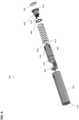
- FIG. 4 illustrates an exploded view of the dental floss dispenser 100.
- one or more of the following components may be disposed in the interior portion 112 of the housing 102: a floss housing 402 coupled to a first or a male latch portion 414, an ejection spring 404, an optional damper ring 406, a latch housing 408 having a bottom portion 410 and a second or female latch portion 412.
- the floss housing 402 may be configured to be removably coupled to the dispensing portion 108 and may be further configured to hold a wound length of dental floss 320 (e.g., as a bobbin, a roll, a coil, etc. (as shown in FIG. 7 ).
- the wound length of dental floss 320 may be interchangeably positioned inside the floss housing 402.
- a new wound length of dental floss 320 may be positioned inside the floss housing 402 upon the user of the dental floss dispenser 100 running out of the previous wound length of dental floss or simply desiring a different dental floss (e.g., thicker, thinner, different flavor, etc.).
- the floss housing 402 may include the first latch portion 414 that may be configured to interact with the second latch portion 412 to temporarily hold an interlocked assembly of the dispensing portion 108 and the floss housing 402.
- the holding of interlocked assembly of the dispensing portion 108 and the floss housing 402 may occur when the user of the dispenser 100 applies a downward force on the top of the dispensing portion 108 to push the dispensing portion 108 into the interior portion 112, whereby the first latch portion 414 may come in contact with and subsequently engage the second latch portion 412 to temporarily hold or lock the interlocked assembly inside the interior portion 112.
- the user may again apply a downward force to the top of the dispensing portion, thereby causing a disengagement of the first latch portion 414 from the second latch portion 412.
- the string 404 may apply force to the bottom of the floss housing 402 and push the dispensing portion 108 away from the interior portion 112 of the housing 102.
- the second latch portion 412 may be positioned inside a latch housing 408 disposed on a latch base 410.
- the latch base 410 may be configured to be coupled to interior walls of the housing 102 (e.g., glued, welded, ultrasonically welded, etc.). In some implementations, the latch base 410 may be further configured to be coupled to the bottom portion 106 (e.g., using a glue, welding, ultrasonic welding, etc.).
- the latch base 410 may have substantially identical size (e.g., diameter) to the bottom portion 106, whereby the bottom portion 106 may have a diameter that is substantially equal to interior diameter of interior portion 112 of the housing 102.
- the latch housing 408 may be configured to be coupled to the latch base 410 (e.g., using a glue, welding, ultrasonic welding, etc.).
- the latch housing 408 may include a hollow interior portion configured to accommodate positioning of the second latch portion 412 (which is shown in further detail in FIG. 8 ).
- the second latch portion 412 may be permanently secured inside the hollow interior portion of the latch housing 408.
- the spring 404 may be configured to have a larger diameter than the exterior diameter of the latch housing 408 to allow positioning of the spring 404 over the latch housing 508. Further, the diameter of the spring 404 may be smaller and/or substantially equal to the exterior diameter of the floss housing 402 (which, in turn, may be substantially similar to the diameter of the dispensing portion 108). In some exemplary implementations, the optional damper ring 406, having an interior diameter greater than the exterior diameter of the housing 408 may be positioned over housing 408 to provide dampening for the spring 404. The damper ring 406 may be sufficiently large enough to fit inside the housing 102 and accommodate positioning of the spring 404 on top of it.
- the floss housing 402 may be configured to include one or more protrusions 416 disposed proximate to the first latch portion 414, as shown in FIG. 4 .
- the protrusions 416 may be configured to interact with an interior lip 418, disposed proximate to the top of the housing 102, to prevent accidental removal of the interlocked assembly of the dispensing portion 108 and the floss housing 402.
- the protrusions 416 may interact with one or more corresponding guides and/or stoppers disposed inside the interior portion 112 of the housing 102 to guide the dispensing portion 108 in and out of the interior portion 112.
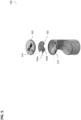
- FIG. 5 illustrates an exploded view of the dispending portion 108 of the dental floss dispenser 100.
- the dispending portion 108 may include the cutting mechanism 110.
- the cutting mechanism 110 may include a cutter 502 having cutting blades 504 (a, b).
- the cutter 502 may be positioned inside a housing of the dispensing portion 108. It may be glued, welded, ultrasonically welded, etc. to any portion of the housing of the dispensing portion 108.
- the blades 504a and 504b may be positioned to ensure that the floss may be protruded through the openings 114 and 315 and between the blades 504a, 504b.
- the blades 504 may be sufficiently sharp to allow cutting of dental floss having any desired thickness.
- the blades 504 may be positioned at a different angle with respect to one another and/or a plane of the cutter 502. To cut a desired length of a string a dental floss, the user may pull the desired length of floss from the opening 114 and then, tilt it to allow cutting on one of the blades 504.
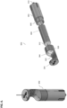
- FIG. 6 illustrates an assembled view (shown on the left side of the figure) and an exploded view (shown on the right side of the figure) of an assembly 602 of the dispensing portion 108 and the floss housing 402.
- the floss housing 402 may include one or more curved protrusions 608 that may be disposed proximate to the top of the floss housing 402.
- the protrusions 608 may have a curvature that may be substantially similar to the interior curvature of the bottom portion 610 of the dispensing portion 108.
- the radius of the curvature of the protrusions 608 may be smaller than the interior radius of the bottom portion 610 to allowing snap-fitting of the protrusions 608 inside the bottom portion 610 to create the interlocked assembly 602, as shown in FIG. 6 .
- a wound string of dental floss 604 may have a diameter that may be smaller than the interior diameter of the floss housing 402 to allow positioning of the wound string of dental floss 604 inside the floss housing 402.
- a free end of the dental floss 320 may be configured to protrude from a top 612 of the wound string of dental floss 604 for insertion through the opening 304 in the dispensing portion 108.
- FIG. 7 illustrates the wound string of dental floss 604.
- the string of floss 320 may be configured to protrude from the top portion 612.
- the string of floss 320 may include a laminated end 702 to allow for ease of insertion through the openings 304, 315 prior to first use (not shown in FIG. 7 ).
- the laminated end 702 may have a harder consistency than the remainder of the dental floss and may be discarded once the dental floss dispenser 100 is ready for its use.
- FIG. 8 illustrates the second or female latch portion 412.
- the second latch portion 412 may be any known push latch that may be configured to accommodate insertion of the first latch portion 414. It may have a base portion 804 that may be configured to be secured within the latch housing 408 (not shown in FIG. 8 ), one or more prongs 802 (a, b), and a push lock 806. Once the first latch portion 414 engages the prongs 802 (e.g., by having the prongs 802 rotate in a scissor-like fashion around the first latch portion 414), the push lock 806 may be configured to engage the base portion 804, thereby preventing unlocking of the prongs 802 from the first latch portion 414.
- the push lock 806 may be configured to disengage from the base portion, thereby releasing or unlocking of the prongs 802 from the first latch portion 414.
- the applied pressure may be a combination of the user pressure on the top of the dispensing portion 108 and the spring 404 (not shown in FIG. 8 ).
- the user may push on the top of the dispensing portion 108 and then remove the interlocked assembly 602 (shown in FIG. 6 ) from the interior portion of the housing 102.
- the spring 404 (along with optional ring 404 (shown in FIG. 4 )) may be retained inside the housing 102.
- the spring 404 (and/or the ring 406) may be removed.
- the user may then disengage the floss housing 402 from the dispensing portion 108. If previous dental floss (or what remains of the wound dental floss 604) is present in the housing 402, the user may remove it (e.g., the dental floss may be retracted from the openings 304, 315 by pulling on it).
- a wound length of dental floss 604 may be positioned inside the housing 402. Then, the laminated end 702 may be protruded through opening 304 and then opening 315, thereby extending it from the top of the dispensing portion 108.
- the housing 402 may then be interlocked with the dispensing portion 108 creating the interlocked assembly 602.
- the interlocked assembly 602 may then be inserted into the interior portion 112 of the housing 102 (if spring 404 and/or ring 406 were previously removed from the interior portion 112, the ring 406 is positioned first on the base 408 and following by the spring 404 (as shown in FIG. 4 )). The user may then push the interlocked assembly 602 further into the interior portion 112 of the housing 102 until first latch portion 414 and the second latch portion 412 engage.
- the user may push on the top portion 104, thereby causing disengagement of the first and second latch portions 414, 412 and ejecting/partially removing the dispensing assembly 108 from the interior portion 112.
- a desired length of string of dental floss 320 may be pulled the concave cavity 308 and protruded through the opening 315 of the cutting mechanism 110 to allow cutting the dental floss using cutting blades 504.
- the user may push on the top portion 104 to secure the dispensing assembly 108 in the interior portion 112.
- any means of securing the dispensing portion may be used (e.g., hook(s), latch(es), ball-and-chain mechanism(s), etc.).
- the current subject matter is not limited to the use of the latching mechanism shown in FIGS. 1a-8 .
- the current subject matter is not limited to the ways of loading dental floss into the dispenser.
- FIG. 9 illustrates an exemplary dispenser 900, not covered by the invention.
- the dispenser 900 may be similar to the dispenser shown in FIGS. 1a-8 .
- the housing 902 may include a rotating portion 904 that may be configured to rotate in a direction A around vertical axis (i.e., axis parallel to the long side of the housing 902).
- a rod 907 may be configured to be disposed inside the housing 902 and may be configured to be coupled (permanently, temporarily, etc.) to the dispensing portion 908 and the rotating portion 904.
- the rod 907 may be configured to have one or more threads disposed thereon along extension of the rod 907 that may allow it to be threaded in and out of the rotating portion 904.
- Rotation of the portion 904 e.g., in a clockwise direction A
- Rotation of the portion 904 in an opposite direction may be configured to thread the rod 907 in the corresponding direction and to pull the dispensing portion 908 into the interior portion of the housing 902 (state 901).
- any methods of pushing out or pulling in the dispensing portion 908 using the rotating portion 904 are possible (e.g., using a screw, a piston, a push button, a spring, a tension-based mechanism, an elastic band, a telescoping rotation device, etc.).
- FIG. 10 illustrates another exemplary dispenser 1000, not covered by the invention.
- the dispenser 1000 may be similar to the dispensers shown in FIGS. 1a-9 .
- it includes a housing 1002 and dispensing portion 1008 that may be configured to be ejected/partially removed/entirely removed from an interior portion of the housing 1002.
- the housing 102 may include a rotating portion 104 that may be configured to rotate in a direction A around vertical axis (i.e., axis parallel to the long side of the housing 1002).
- the portion 1004 may be configured to be disposed substantially at an end of the dispenser 1000 that distal to the end of the dispensing portion 1008. Similar to FIG.
- rotation of the portion 1004 may be configured to push dispensing portion 1008 out from the interior portion of the housing 1002 (state 1003).
- Rotation of the portion 1004 in an opposite direction may be configured to pull the dispensing portion 1008 into the interior portion of the housing 1002 (state 1001).
- any methods of pushing out or pulling in the dispensing portion 1008 using the rotating portion 1004 are possible (e.g., using a screw, a piston, a push button, a spring, a tension-based mechanism, an elastic band, etc.).
- the user may be configured to use a user's finger to push on the portion 1004, thereby causing the dispensing portion 1008 to be ejected/partially removed/entirely removed from the interior portion of the housing 1002.
- the user may apply force to the top of the dispensing portion 1008, until it is entirely located within the housing 1002.
- Any means of securing the dispensing portion 1008 may be used (e.g., hook(s), latch(es), ball-and-chain mechanism(s), etc.).
- FIG. 11 illustrates yet another exemplary dispenser 1100, not covered by the invention.
- the dispenser 1100 may be similar to the dispensers shown in FIGS. 1a-10 .
- the housing may also include a cap 1104.
- the cap 1104 may be configured to be entirely removable (e.g., state 1103), partially removable (e.g., the cap 1104 may be coupled to the housing 1102 using a hinge, a spring-loaded hinge, a latch, etc.), etc.
- the cap 1104 may be screw cap, twist on/off cap, snap on/off cap, push/pull cap, friction-fit cap, and/or any other type of cap.
- the cap 1104 may be configured to conceal the dispensing portion 1108 (e.g., state 1101) when the dispensing portion is not in use.
- the cap 1104 may be configured to cover the top of the housing 1102, while the dispensing portion 1108 is contained inside the interior portion of the housing 1102 (e.g., as shown in FIGS. 1a , 9-10 ).
- the user may remove the cap 1104 (e.g., state 1103), e.g., by twisting the cap off, by unscrewing it, by pulling on it, etc., and then use the dispensing portion 1108.
- the dispensing portion 1108 may also be ejected or partially removed from the interior portion of the housing 1102. Any means of securing and/or removing the cap 1104 to/from the housing 1102 may be used.
- FIG. 12 illustrates yet another exemplary dispenser 1200, not covered by the invention.
- the dispenser 1200 may be similar to the dispenser 1100 shown in FIG. 11 .
- the dispenser 1200 may include a housing 1202 and dispensing portion 1208.
- the housing may also include a flip cover and/or a hinged cover 1204.
- the cover 1204 may be configured to be hingedly coupled to the housing 1202 and may be configured to be opened (state 1203) and closed (state 1201) using, for example, a hinge 1207
- the dispensing portion 1208 may be exposed (alternatively, the user may need to eject or partially remove the dispensing portion 1208, as discussed above) and the user may use the dispenser 1200 for flossing as discussed above. Any means of securing and/or removing the cover 1204 to/from the housing 1202 may be used.
- FIG. 13 illustrates yet another exemplary dispenser 1300, not covered by the invention.
- the dispenser 1300 may be similar to the dispenser shown in FIG. 11 .
- the housing may also include a sliding cover 1304.
- the cover 1304 may be configured to be slide along an outer surface of the housing 1302 for the purposes of concealing the dispensing portion 1308 (e.g., state 1301) and exposing the dispensing portion 1308 (e.g., state 1303).
- the cover 1304 may slide on rails, roller balls, gears, etc. Alternatively, the sliding cover 1304 may be threaded on/off for the purposes of concealing/exposing the dispensing portion 1308.
- the cover 1304 may be configured to cover the top of the housing 1302 (similar to FIG. 11 ), while the dispensing portion 1308 is contained inside the interior portion of the housing 1302 (e.g., as shown in FIGS. 1a , 9-11 ).
- the user may slide the cover 1304 down (e.g., state 1303) and then use the dispensing portion 1308.
- the dispensing portion 1308 may also be ejected or partially removed from the interior portion of the housing 1302. Any means of securing and/or removing the cover 1304 to/from the housing 1302 may be used.
- FIG. 14 illustrates yet another exemplary dispenser 1400, not covered by the invention.
- the dispenser 1400 may be similar to the dispensers shown in FIG. 1a-13 .
- the dispenser 1400 may include a housing 1402 and dispensing portion 1408, as discussed above.
- the housing 1402 may also include a button 1404.
- the button may be used to eject or partially remove (state 1403) and/or conceal (state 1401) the dispensing portion 1408 from and/or into the interior portion of the housing 1402. Once the button 1404 is pressed, the dispensing portion 1408 may slide inside the housing 1402; upon pressing the button 1404 the next time, the dispensing portion 1408 may slide out of the housing 1402.
- the button 1404 may be coupled to a mechanical, electrical, electronic, electro-mechanical and/or any combination thereof, mechanism that may trigger movement of the dispensing portion 1408.
- FIG. 15 illustrates an exemplary process for loading a dispenser 1500 (similar to dispensers shown in FIGS. 1a-14 ) with a dental floss 1504, according to some implementations of the current subject matter.
- the dental floss 1504 may be loaded into the housing 1502 from the bottom of the housing 1502.
- a bottom portion 1507 may be opened (state 1501) and the dental floss 1504 may be inserted in an upward direction (i.e., direction A).
- the bottom portion 1507 may be closed (state 1503).
- the bottom portion 1507 may be hingedly coupled to the housing 1502, may be entirely removable from the housing 1502, may be snapped on/off the housing 1502, may be clipped on/off the housing 1502, and/or otherwise coupled to the housing in any desired way.
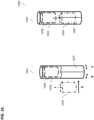
- FIG. 16 illustrates an exemplary process for loading a dispenser 1600 (similar to dispensers shown in FIGS. 1a-14 ) with a dental floss 1604, not covered by the invention.
- the housing 1602 of the dispenser 1600 may include an access structure 1607.
- the structure 1607 may be a single or a double side door, a vertical clam-shell structure, a horizontal clam-shell structure, and/or any other structure that may allow positioning of the dental floss 1604 inside the interior portion 1602 of the dispenser 1600.
- the housing 1602 may include a vertical clam-shell structure 1607 that may be configured to allow opening (e.g., rotation in directions B and C) on of the housing 1602 to expose the interior portion of the housing 1602.
- the dental floss 1604 may be placed inside the housing 1602 (e.g., as shown by direction A) and the clam-shell structure 1607 may be closed (state 1603), thereby concealing the interior portion of the housing 1602.
- the access structure 1607 may include at least one of the following: one or more hinges, one or more locks, one more hooks, one or more snaps, and/or any other mechanisms.
- the housing of the dispenser may include storage space that may allow storage of various items, such as, but not limited to, toothpaste, toothpicks, floss picks, medication, toothbrush head(s), money, food, etc.
- the space may accessed using any of the means discussed above.
- the dispensing portion 108, 308 e.g., as shown in FIGS. 1 , 3a-c ) may be substituted for and/or replaced with a toothbrush and/or any other device.
- the dispensing portion 108, 308 may be removed (e.g., by detaching, unscrewing, unclipping, unsnapping, etc.) and a toothbrush (and/or a toothbrush head, a toothbrush head with a handle, etc.) may be positioned instead of the dispensing portion, such as by attaching, screwing, clipping, snapping, etc.
- the toothbrush may be moved in and out of the housing of the dispenser in a similar fashion as the dispensing portion 108, 308.
- the toothbrush can be permanently positioned within the housing of the dispenser.
- the dispensing portion 108, 308 may be substituted (either temporarily and/or permanently) with any other tools (dental or otherwise, e.g., floss picks (small or large), toothpicks, scissors, hair combs/brushes, filers, nail clippers, screwdrivers, pliers, etc.).
- any other tools dental or otherwise, e.g., floss picks (small or large), toothpicks, scissors, hair combs/brushes, filers, nail clippers, screwdrivers, pliers, etc.).
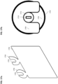
- FIGS. 17a-e illustrates an exemplary dental floss supporting/stabilization structure 1702, not covered by the invention.
- the structure 1702 may be used for securing/stabilizing the wound string of dental floss 604 (e.g., a bobbin, a roll, etc.), as shown in FIG. 6 .
- the structure 1702 may be configured to wrap the wound string of dental floss 604, thereby improving dispensing of the dental floss from the dental floss dispenser shown in FIGS. 1a-16 , preventing tangling of dental floss string, etc.
- a cover 1712 e.g., a rubber disk, a pill, etc.
- the cover 1712 may include a slit 1710 that may be used for threading a string 320 of the dental floss.
- the cover 1712 may be placed on top of the bobbin 604 (as shown in FIG. 17e ).
- the bobbin may be configured to be coreless, e.g., there is no core (e.g., paper, plastic, etc.) structure in the center of the bobbin, whereby the dental floss may unwind from the center of the bobbin rather than from the outside.
- the floss may be configured to unwind from any location on the bobbin.
- the wound string of dental floss (or a refill of dental floss) may be configured as a cylindrical bobbin 604.
- the bobbin 604 may have various shapes, sizes, lengths of floss wrapped in, thickness of floss, etc.
- the support structure 1702 may be configured as a wrap that may include an adhesive backing disposed on one side of the structure 1702.
- the adhesive may be safe for use with the dental floss, and thus, safe for use for the user.
- the support structure may be wrapped around the bobbin 604.
- the support structure may include tabs 1704 and 1706.
- the tabs 1704, 1706 may be configured to protrude away from an edge of the structure 1702, as shown in FIG. 17a .
- the tabs 1704, 1706 may be configured as two-prong structures having spaces 1703, 1705, respectively.
- the spaces 1703, 1705 may be used for positioning around the cover 1712, as shown in FIG. 17b .
- the prong structures 1704, 1706 may be shaped differently, as for example is shown in FIG. 17a , and may be configured to include an adhesive backing.
- the structure 1702 may be adhesively coupled to the bobbin 604, with the prongs 1704 and 1706 being aligned in the same direction as a string of floss.
- the floss may be threaded through the slit 1710 of the cover 1712.
- the bobbin 604 may be rotated in a direction A (as shown in FIG. 17d ) to wrap the structure 1702 around the bobbin 604.
- the structure 1702 may be wrapped around the bobbin 604 without rotating the bobbin 604.
- the tab 1704 may be lowered on top of the cover 312 (the tab 1704 may include an adhesive backing and thus, be adhesively coupled to the cover 312).
- the second tab 1706 may be placed on top of the first tab 1704, as shown in FIGS. 17b and 17e .
- the tab 1706 may be without any adhesive backing, which may assist the user of the dental floss dispenser in easily removing the spent dental floss refill by simply pulling on the tab 1706.
- the dispensing end 702 of the dental floss 320 may be threaded through the slit 1712 in the cover 1710.
- the cover 1710 along with the slit 1712 may provide a friction drag onto the dental floss 320 as it is dispensed to prevent the dental floss 320 from dispensing unintentionally and may further provide tension on the dental floss 320 which may assist during the floss cutting process.
- the bobbin 604 and cover 1712 may be wrapped together by rolling the adhesive structure 1702 around the bobbin and the cover. This may ensure that the surface of the bobbin 604 is adhered to the structure 1702.
- the adhesive structure 1702's tabs 1704, 1706 may be shaped and positioned to allow for the cover 1712 to be securely fastened to the bobbin 604 while allowing the dental floss 320 to pass freely through the slit 1710.
- the dispensing end of the dental floss may be rigidized (e.g., using a wax coating 702) to allow the user to easily thread that end into the dispenser device.
- the structure 1702 may provide a rigid structure for the outer windings of floss in the floss bobbin 604, where such windings may be configured to adhere to the structure 1702.
- the bobbin 604 may collapse inwards and/or may cause tangling and/or knotting of the dental floss. Moreover, the structure 1702 may allow the full length of the bobbin 604 to be dispensed without knotting and/or tangling.
- the user may remove the cap portion of the dispenser device, grasp the loose tabs 1704 and/or 1706 from the refill, and pull the empty adhesive wrap out of the dispenser device to thereby remove the adhered cover simultaneously.
- the user may place the new bobbin 604 into the dispenser device with the dispensing end of the floss pointed upwards. The user may then thread the rigidized portion of dental floss through the cap of the dispenser device, replace the cap to the dispenser device, and press down firmly until the cap "clicks" into place.
- any components of the dispenser are not limited to those shown in FIGS. 1a-17e .
- the dispenser and/or any of its components may have cylindrical shape(s), cubical shape(s), circular shape(s), square shape(s), rectangular shape(s), irregular shape(s), and/or any other shapes.
- the dental floss dispenser may include a dispenser housing 102 enclosing an interior portion and a dispensing portion 108 slidably positioned inside the interior portion of the dispenser housing.
- the dispensing portion 108 may have a stored position (e.g., as shown in FIGS. 1a-b ) and a dispensing position (e.g., as shown in FIGS. 3a-c ). In the stored position, the dispensing portion may be entirely disposed in the interior portion. In the dispensing position, the dispensing portion may be partially disposed outside of the interior portion.
- the dispensing portion may further include a storage chamber (e.g., floss housing 402) for storing a wound string of dental floss (e.g., dental floss 604) and a floss dispensing cavity (e.g., floss holding section 306) for holding at least a portion of the wound string of dental floss extracted from the storage chamber.
- a storage chamber e.g., floss housing 402 for storing a wound string of dental floss (e.g., dental floss 604) and a floss dispensing cavity (e.g., floss holding section 306) for holding at least a portion of the wound string of dental floss extracted from the storage chamber.
- the dental floss dispenser may further include a locking mechanism (e.g., as shown in FIGS. 4 and 8 ) configured to temporarily retain the dispensing portion in the stored position or the dispensing position.
- the locking mechanism may include a spring component (e.g., spring 404) and a latching component (e.g., latch portions 414, 412, 408).
- the spring component upon unlocking of the latching component, may be configured to position the dispensing portion in the dispensing position.
- the latching component upon locking, may be configured to retain the dispensing portion in the stored position.
- the dispensing portion may be configured to be entirely removable from the interior portion of the dispenser housing (e.g., as shown in FIGS. 4 and 6 ).
- the wound string of dental floss may be configured to be removable from the storage chamber upon entire removal of the dispensing portion from the interior portion of the dispenser housing.
- the wound string of dental floss may be configured to be wound in a coreless manner (e.g., without a core structure).
- a support structure e.g., wrap 1702 shown in FIGS. 17a-e
- the support structure may be configured to adhesively wrap the wound string of dental floss.
- the wound string of dental floss may be further configured to unwind from an interior of the wound string of dental floss.
- the wound string of dental floss may be configured to have one or more exterior dimensions smaller than one or more interior dimensions of the storage chamber.
- the wound string of dental floss may include a laminated end (e.g., end 702).
- the wound string of dental floss may be configured to be wound in at least one of the following shapes: a cylinder, a tube, a roll, a torus, a sphere, a cone, a prism, an ellipsoid, a helix, and any combination thereof.
- the dispensing portion may include a concave open cavity (e.g., cavity 308) having a top 311 and a bottom 313, a first opening 304 disposed in the bottom and configured for protruding the portion of the wound string of dental floss from the storage chamber, and a second opening 315 disposed in the top and configured for holding the protruded portion of the wound string of dental floss.
- the second opening of the concave open cavity may include a cutting mechanism (e.g., cutting mechanism 502) for cutting the dental floss.
- the dispenser housing may include a stopping mechanism (e.g., lip 418) disposed in the interior portion proximate to a top of the dispenser housing.
- the dispensing portion may include one or more protrusions (e.g., protrusions 416) disposed on an exterior surface of the dispensing portion.
- the stopping mechanism may be configured to interact with one or more protrusions to temporarily prevent removal of the dispensing portion from the interior portion of the dispenser housing.
- the storage chamber may be configured to be interlocked with the floss dispensing cavity for holding the wound string of dental floss (e.g., as shown in FIG. 6 ).
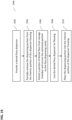
- FIG. 18 illustrates an exemplary method 1800 for loading the dental floss dispenser with a dental floss.
- the dental floss dispenser as described above, may be provided.
- the dispensing portion may be removed from the interior portion of the dispenser housing.
- the wound string of dental floss may be inserted into the storage chamber.
- at least a portion of the wound string of dental floss may be extracted from the storage chamber and the extracted portion of the wound string of dental floss may be positioned across the floss dispensing cavity (e.g., as shown in FIG. 3c ).
- the dispensing portion may be placed into the interior portion of the dispenser housing.
- FIG. 19 illustrates an exemplary method 1900 for using the dental floss dispenser described above.
- the method 1900 may include providing the dental floss dispenser, as described above, at 1902.
- the dispensing portion may be partially removed from the interior portion of the dispenser housing.
- at 1904 at least a portion of dental floss may be extracted from the storage chamber and the extracted portion may be secured to the floss dispensing cavity.
- the dental floss dispenser may be used for flossing.
- the dispensing portion may be placed into the interior portion of the dispenser housing.
Landscapes
- Health & Medical Sciences (AREA)
- Dentistry (AREA)
- Epidemiology (AREA)
- Life Sciences & Earth Sciences (AREA)
- Animal Behavior & Ethology (AREA)
- General Health & Medical Sciences (AREA)
- Public Health (AREA)
- Veterinary Medicine (AREA)
- Dental Tools And Instruments Or Auxiliary Dental Instruments (AREA)
- Brushes (AREA)
Description
- The present application claims priority to
U.S. Provisional Patent Appl. No. 62/900,930 to May et al., filed September 16, 2019 - The current subject-matter refers to a dental floss dispenser.
-
US 2007/209953 A1 discloses a dental floss dispenser, comprising:a dispenser housing enclosing an interior portion; anda dispensing portion slidably positioned inside the interior portion of the dispenser housing, the dispensing portion having a stored position and a dispensing position, wherein, in the stored position, the dispensing portion is entirely disposed in the interior portion, and, in the dispensing position, the dispensing portion is partially disposed outside of the interior portion;the dispensing portion including a storage chamber for storing a wound string of dental floss and a floss dispensing cavity for holding at least a portion of the wound string of dental floss extracted from the storage chamber; and a locking mechanism configured to temporarily retain the dispensing portion in stored position or the dispensing position wherein the locking mechanism including a latching component, wherein the latching component, upon locking, is configured to retain the dispensing portion in the stored position. To maintain good oral health, it is recommended that teeth are not only brushed but also flossed using a dental floss. Dental floss typically comes in a string form and is generally dispensed from a bobbin contained within a dispenser housing. A cutting device is used to cut a desired length of dental floss string. A user can then use the cut length of floss string to insert it between the teeth for flossing. Other variations of dental floss appliances include pre-fabricated picks having a short piece of floss spanning across two supports. These picks generally come in packs and are single use items. Once used, the entire pick and used floss are discarded. There is a need to provide a more efficient and effective way of storing and dispensing of dental floss. - The current subject-matter refers to a dental floss dispenser. The dispenser may include a dispenser housing having an interior portion and a dispensing portion slidably disposed inside the interior portion of the dispenser housing. A wound string of dental floss may be disposed within a dental floss housing portion. The dental floss housing portion may be removably coupled to the dispensing portion. The dispenser may further include a locking mechanism configured to temporarily retain the dispensing portion and the dental floss housing portion in the interior portion of the dispenser housing. A portion of the wound string of dental floss may be configured to protrude through one or more openings in the dispensing portion.
- In some implementations, the current subject matter relates to a method for loading the dental floss dispenser. To load the dispenser, a user may push on a top of the dispensing portion and remove an interlocked assembly of the dispensing portion and the dental floss housing from the interior portion of the dispenser housing. In some implementations, a spring (along with optional damper ring) may be retained inside the dispenser housing. Alternatively, the spring (and/or the damper ring) may be removed. The user may then disengage the floss housing from the dispensing portion. If previous dental floss (or any remains of the wound dental floss) is present in the dental floss housing, the user may remove it (e.g., the dental floss may be retracted from the openings in the dispensing portion by pulling on it). If no dental floss is present, a new wound length of dental floss may be positioned inside the dental floss housing. Then, a laminated end of the new wound length of dental floss may be protruded through openings in the dispensing portion, thereby extending it from the top of the dispensing portion. The dental floss housing may then be interlocked with the dispensing portion creating the interlocked assembly. The interlocked assembly may then be inserted into the interior portion of the dispenser housing (if spring and/or damper ring were previously removed from the interior portion, the damper ring is positioned first on the base and following by the spring). The user may then push the interlocked assembly further into the interior portion of the dispenser housing until a first latch portion and a second latch portion of the locking mechanism engage.
- To use the dispenser, the user may push on its top portion, thereby causing disengagement of the first and second latch portions and ejecting/partially removing the dispensing assembly from the interior portion. A desired length of string of dental floss may be pulled a concave cavity of the dispensing portion and protruded through one or more openings in the dispensing portion to allow cutting the dental floss using one or more cutting blades. Once flossing is complete, the user may push on the top portion to secure the dispensing portion in the interior portion.
- In some implementations, the current subject matter relates to a dental floss dispenser. The dental floss dispenser may include a dispenser housing enclosing an interior portion and a dispensing portion slidably positioned inside the interior portion of the dispenser housing. The dispensing portion may have a stored position and a dispensing position. In the stored position, the dispensing portion may be entirely disposed in the interior portion. In the dispensing position, the dispensing portion may be partially disposed outside of the interior portion. The dispensing portion may further include a storage chamber for storing a wound string of dental floss and a floss dispensing cavity for holding at least a portion of the wound string of dental floss extracted from the storage chamber.
- In some implementations, the current subject matter may include one or more of the following optional features. The dental floss dispenser may further include a locking mechanism configured to temporarily retain the dispensing portion in stored position or the dispensing position. The locking mechanism may include a spring component and a latching component. The spring component, upon unlocking of the latching component, may be configured to position the dispensing portion in the dispensing position. The latching component, upon locking, may be configured to retain the dispensing portion in the stored position.
- In some implementations, the dispensing portion may be configured to be entirely removable from the interior portion of the dispenser housing. The wound string of dental floss may be configured to be removable from the storage chamber upon entire removal of the dispensing portion from the interior portion of the dispenser housing. The wound string of dental floss may be configured to be wound in a coreless manner. In some implementations, a support structure may be configured to wrap the wound string of dental floss. The support structure may be configured to adhesively wrap the wound string of dental floss. The wound string of dental floss may be further configured to unwind from an interior of the wound string of dental floss. The wound string of dental floss may be configured to have one or more exterior dimensions smaller than one or more interior dimensions of the storage chamber. The wound string of dental floss may include a laminated end. The wound string of dental floss may be configured to be wound in at least one of the following shapes: a cylinder, a tube, a roll, a torus, a sphere, a cone, a prism, an ellipsoid, a helix, and any combination thereof.
- In some implementations, the dispensing portion may include a concave open cavity having a top and a bottom, a first opening disposed in the bottom and configured for protruding the portion of the wound string of dental floss from the storage chamber, and a second opening disposed in the top and configured for holding the protruded portion of the wound string of dental floss. The second opening of the concave open cavity may include a cutting mechanism for cutting the dental floss.
- In some implementations, the dispenser housing may include a stopping mechanism disposed in the interior portion proximate to a top of the dispenser housing. The dispensing portion may include one or more protrusions disposed on an exterior surface of the dispensing portion. The stopping mechanism may be configured to interact with one or more protrusions to temporarily prevent removal of the dispensing portion from the interior portion of the dispenser housing.
- In some implementations, the storage chamber may be configured to be interlocked with the floss dispensing cavity for holding the wound string of dental floss.
- In some implementations, the current subject matter relates to a method of loading the dental floss dispenser described above. The method may include providing the dental floss dispenser, as described above, removing the dispensing portion from the interior portion of the dispenser housing, inserting the wound string of dental floss into the storage chamber, extracting at least a portion of the wound string of dental floss from the storage chamber and positioning the extracted portion of the wound string of dental floss across the floss dispensing cavity, and placing the dispensing portion into the interior portion of the dispenser housing.
- In some implementations, the current subject matter relates to a method of using the dental floss dispenser described above. The method may include providing the dental floss dispenser, as described above, partially removing the dispensing portion from the interior portion of the dispenser housing, extracting at least a portion of dental floss from the storage chamber and securing the extracted portion to the floss dispensing cavity, using the dental floss dispenser for flossing, and placing the dispensing portion into the interior portion of the dispenser housing.
- The details of one or more variations of the subject matter described herein are set forth in the accompanying drawings and the description below. Other features and advantages of the subject matter described herein will be apparent from the description and drawings, and from the claims.
- The accompanying drawings, which are incorporated in and constitute a part of this specification, show certain aspects of the subject matter disclosed herein and, together with the description, help explain some of the principles associated with the disclosed implementations. In the drawings,
-
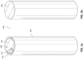
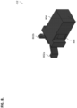
FIGS. 1a-b illustrate perspective top and bottom views, respectively, of the dental floss dispenser, according to some implementations of the current subject matter; -
FIGS. 2a-b illustrate top and bottom views, respectively, of the top and bottom portions of the dispenser shown inFIGS. 1a-b ; -
FIGS. 3a-c illustrate the dental floss dispenser shown inFIGS. 1a-b with the dispensing portion being ejected or partially removed from the interior portion, according to some implementations of the current subject matter; -
FIG. 4 illustrates an exploded view of the dental floss dispenser shown inFIGS. 1a-b ; -
FIG. 5 illustrates an exploded view of the dispending portion of the dental floss dispenser shown inFIGS. 1a-b ; -
FIG. 6 illustrates an assembled view (shown on the left side of the figure) and an exploded view (shown on the right side of the figure) of an assembly of the dispensing portion and the floss housing, according to some implementations of the current subject matter; -
FIG. 7 illustrates the wound string of dental floss, according to some implementations of the current subject matter; -
FIG. 8 illustrates the second or female latch portion, according to some implementations of the current subject matter; -
FIG. 9-14 illustrate various exemplary dental floss dispensers, not covered by the invention; -
FIGS. 15-16 illustrate various exemplary processes for loading dispensers (e.g., dispensers shown inFIGS. 1a-14 ) with a dental floss, not covered by the invention; -
FIGS. 17a-e illustrate exemplary protection/stabilization structure for a dental floss, not covered by the invention; -
FIG. 18 illustrates an exemplary method for loading a dental floss dispenser, and -
FIG. 19 illustrates an exemplary method for using a dental floss dispenser. - In some implementations, the current subject matter relates to a dental floss dispensing mechanism and methods of use.
FIGS. 1a-b illustrate perspective top and bottom views, respectively, of thedental floss dispenser 100. Thedental floss dispenser 100 may include ahousing 102 having a hollow interior portion 112, atop portion 104, and abottom portion 106.FIGS. 2a-b illustrate top and bottom views, respectively, of the top andbottom portions housing 102 may be sized to hold a dispensingportion 108 that may be configured to be ejected and/or removed from the interior portion 112. Thehousing 102 may be configured to have a cylindrical shape. As can be understood, thehousing 102 may have any other shape, e.g., cube, parallelogram, and/or any other desired shape. Thebottom portion 106 may be configured to have a circular shape and may be coupled to thehousing 102 by any desired means (e.g., glued, welded, detachably attached, forming a unitary structure with thehousing 102, etc.). - In a stored position, the dispensing
portion 108 may be disposed entirely within thehousing 102, as shown inFIGS. 1a-b . In this position, the top of the dispensingportion 108 may be flush with thetop portion 104. In an ejected/partially removed position, the dispensingportion 108 may be removed from the interior portion 112, as shown inFIGS. 3a-c . In some implementations, the dispensingportion 108 may also be entirely removed from the interior portion 112. - As stated above, the dispensing
portion 108 may be configured to be ejected/removed/partially removed from thetop portion 104 of thehousing 102. The dispensingportion 108 may be ejected/removed/partially removed using a spring and/or a latch mechanisms disposed in the interior portion 112 of the housing 102 (not shown inFIGS 1a-2b ). The dispensingportion 108 may be ejected/removed/partially removed from thetop portion 104 of thehousing 102 by application of a downward force on and subsequent release of the top of the dispensingportion 108, thereby allowing the dispensingportion 108 to "pop out" from the interior portion 112 of the housing 102 (as shown inFIGS. 3a-c ). The dispensingportion 108 may be returned to the interior portion 112 of thehousing 102 by application of the downward force on the top of the dispensingportion 108 and pushing the dispensingportion 108 into the interior portion 112 until the dispensingportion 108 is locked inside the interior portion 112 using a locking mechanism (not shown inFIGS. 1a-2b ). - The dispensing
portion 108 may also include acutting mechanism 110 that may be used to cut a desired length of a string of dental floss protruding from an interior of the dispensingportion 108. Thecutting mechanism 110 may include one or more cutting blades that may be used by a user of the dentalfloss dispensing mechanism 100 to cut the string of dental floss. The cutting blades may be disposed inside anopening 114 disposed in the top of the dispensingportion 108. - In some implementations, the dispensing
portion 108 may be configured to have a size (e.g., a diameter) that is smaller than an interior diameter of the interior portion 112. This may allow ejection/removal/partial removal of the dispensingportion 108 from the interior portion 112. In some exemplary implementations, a difference in the diameter of the dispensingportion 108 and the interior diameter of the interior portion 112 may create a small cylindrical space that may allow ease of ejection/removal/partial removal of the dispensingportion 108 from the interior portion 112. -
FIGS. 3a-c illustrate thedental floss dispenser 100 with the dispensingportion 108 being ejected or partially removed from the interior portion 112 (perspective, front, and side views are shown inFIGS. 3a-c , respectively). The dispensingportion 108 may include a dentalfloss holding section 306 disposed below atop portion 302. - As shown in
FIGS. 3a-c , thedental floss section 306 may include aconcave section 308 having atop portion 311 and abottom portion 313. Theconcave section 308 may be configured to accommodate placement of user's fingers to pull on a string of floss from an interior of the dispensingportion 108. Thetop portion 311 may be configured to include anentry port 315 for thecutting mechanism 110. Thebottom portion 313 may be configured to include anopening 304. A string ofdental floss 320 may be configured to protrude from an interior of the dispensingportion 108 through theopening 304 and into theentry port 315. In some implementations, one or more floss holding mechanisms may be disposed inside theopening 304 and/orentry port 315 to ensure that the floss is held in position before and/or after cutting. The holding mechanisms (e.g., spring-loaded clips, etc.) may allow the user to pull on a string of dental floss protruding from thetop portion 302 of the dispensingportion 108 and once a sufficient length of dental floss is pulled out, the mechanisms may retain the dental floss between the top andbottom portions -
FIG. 4 illustrates an exploded view of thedental floss dispenser 100. As shown inFIG. 4 , in addition to the dispensingportion 108, one or more of the following components may be disposed in the interior portion 112 of the housing 102: afloss housing 402 coupled to a first or amale latch portion 414, anejection spring 404, anoptional damper ring 406, alatch housing 408 having abottom portion 410 and a second orfemale latch portion 412. Thefloss housing 402 may be configured to be removably coupled to the dispensingportion 108 and may be further configured to hold a wound length of dental floss 320 (e.g., as a bobbin, a roll, a coil, etc. (as shown inFIG. 7 ). The wound length ofdental floss 320 may be interchangeably positioned inside thefloss housing 402. For example, a new wound length ofdental floss 320 may be positioned inside thefloss housing 402 upon the user of thedental floss dispenser 100 running out of the previous wound length of dental floss or simply desiring a different dental floss (e.g., thicker, thinner, different flavor, etc.). - The
floss housing 402 may include thefirst latch portion 414 that may be configured to interact with thesecond latch portion 412 to temporarily hold an interlocked assembly of the dispensingportion 108 and thefloss housing 402. The holding of interlocked assembly of the dispensingportion 108 and thefloss housing 402 may occur when the user of thedispenser 100 applies a downward force on the top of the dispensingportion 108 to push the dispensingportion 108 into the interior portion 112, whereby thefirst latch portion 414 may come in contact with and subsequently engage thesecond latch portion 412 to temporarily hold or lock the interlocked assembly inside the interior portion 112. To unlock the temporary hold of the interlocked assembly, the user may again apply a downward force to the top of the dispensing portion, thereby causing a disengagement of thefirst latch portion 414 from thesecond latch portion 412. Once disengaged, thestring 404 may apply force to the bottom of thefloss housing 402 and push the dispensingportion 108 away from the interior portion 112 of thehousing 102. - The
second latch portion 412 may be positioned inside alatch housing 408 disposed on alatch base 410. Thelatch base 410 may be configured to be coupled to interior walls of the housing 102 (e.g., glued, welded, ultrasonically welded, etc.). In some implementations, thelatch base 410 may be further configured to be coupled to the bottom portion 106 (e.g., using a glue, welding, ultrasonic welding, etc.). Thelatch base 410 may have substantially identical size (e.g., diameter) to thebottom portion 106, whereby thebottom portion 106 may have a diameter that is substantially equal to interior diameter of interior portion 112 of thehousing 102. Thelatch housing 408 may be configured to be coupled to the latch base 410 (e.g., using a glue, welding, ultrasonic welding, etc.). In some implementations, thelatch housing 408 may include a hollow interior portion configured to accommodate positioning of the second latch portion 412 (which is shown in further detail inFIG. 8 ). Thesecond latch portion 412 may be permanently secured inside the hollow interior portion of thelatch housing 408. - The
spring 404 may be configured to have a larger diameter than the exterior diameter of thelatch housing 408 to allow positioning of thespring 404 over the latch housing 508. Further, the diameter of thespring 404 may be smaller and/or substantially equal to the exterior diameter of the floss housing 402 (which, in turn, may be substantially similar to the diameter of the dispensing portion 108). In some exemplary implementations, theoptional damper ring 406, having an interior diameter greater than the exterior diameter of thehousing 408 may be positioned overhousing 408 to provide dampening for thespring 404. Thedamper ring 406 may be sufficiently large enough to fit inside thehousing 102 and accommodate positioning of thespring 404 on top of it. - In some implementations, the
floss housing 402 may be configured to include one ormore protrusions 416 disposed proximate to thefirst latch portion 414, as shown inFIG. 4 . Theprotrusions 416 may be configured to interact with aninterior lip 418, disposed proximate to the top of thehousing 102, to prevent accidental removal of the interlocked assembly of the dispensingportion 108 and thefloss housing 402. Alternatively, theprotrusions 416 may interact with one or more corresponding guides and/or stoppers disposed inside the interior portion 112 of thehousing 102 to guide the dispensingportion 108 in and out of the interior portion 112. -
FIG. 5 illustrates an exploded view of thedispending portion 108 of thedental floss dispenser 100. As stated above, thedispending portion 108 may include thecutting mechanism 110. Thecutting mechanism 110 may include acutter 502 having cutting blades 504 (a, b). Thecutter 502 may be positioned inside a housing of the dispensingportion 108. It may be glued, welded, ultrasonically welded, etc. to any portion of the housing of the dispensingportion 108. Theblades openings blades cutter 502. To cut a desired length of a string a dental floss, the user may pull the desired length of floss from theopening 114 and then, tilt it to allow cutting on one of the blades 504. -
FIG. 6 illustrates an assembled view (shown on the left side of the figure) and an exploded view (shown on the right side of the figure) of anassembly 602 of the dispensingportion 108 and thefloss housing 402. For interlocking of the dispensingportion 108 and thefloss housing 402, thefloss housing 402 may include one or morecurved protrusions 608 that may be disposed proximate to the top of thefloss housing 402. Theprotrusions 608 may have a curvature that may be substantially similar to the interior curvature of the bottom portion 610 of the dispensingportion 108. The radius of the curvature of theprotrusions 608 may be smaller than the interior radius of the bottom portion 610 to allowing snap-fitting of theprotrusions 608 inside the bottom portion 610 to create the interlockedassembly 602, as shown inFIG. 6 . - A wound string of dental floss 604 (e.g., a bobbin, a coil, etc.) may have a diameter that may be smaller than the interior diameter of the
floss housing 402 to allow positioning of the wound string ofdental floss 604 inside thefloss housing 402. A free end of thedental floss 320 may be configured to protrude from a top 612 of the wound string ofdental floss 604 for insertion through theopening 304 in the dispensingportion 108. -
FIG. 7 illustrates the wound string ofdental floss 604. As stated above, the string offloss 320 may be configured to protrude from the top portion 612. In some implementations, the string offloss 320 may include alaminated end 702 to allow for ease of insertion through theopenings FIG. 7 ). Thelaminated end 702 may have a harder consistency than the remainder of the dental floss and may be discarded once thedental floss dispenser 100 is ready for its use. -
FIG. 8 illustrates the second orfemale latch portion 412. Thesecond latch portion 412 may be any known push latch that may be configured to accommodate insertion of thefirst latch portion 414. It may have abase portion 804 that may be configured to be secured within the latch housing 408 (not shown inFIG. 8 ), one or more prongs 802 (a, b), and apush lock 806. Once thefirst latch portion 414 engages the prongs 802 (e.g., by having the prongs 802 rotate in a scissor-like fashion around the first latch portion 414), thepush lock 806 may be configured to engage thebase portion 804, thereby preventing unlocking of the prongs 802 from thefirst latch portion 414. Upon application of sufficient pressure, thepush lock 806 may be configured to disengage from the base portion, thereby releasing or unlocking of the prongs 802 from thefirst latch portion 414. The applied pressure may be a combination of the user pressure on the top of the dispensingportion 108 and the spring 404 (not shown inFIG. 8 ). - In some implementations, to load the
dispenser 100, the user may push on the top of the dispensingportion 108 and then remove the interlocked assembly 602 (shown inFIG. 6 ) from the interior portion of thehousing 102. In some implementations, the spring 404 (along with optional ring 404 (shown inFIG. 4 )) may be retained inside thehousing 102. Alternatively, the spring 404 (and/or the ring 406) may be removed. The user may then disengage thefloss housing 402 from the dispensingportion 108. If previous dental floss (or what remains of the wound dental floss 604) is present in thehousing 402, the user may remove it (e.g., the dental floss may be retracted from theopenings dental floss 604 may be positioned inside thehousing 402. Then, thelaminated end 702 may be protruded throughopening 304 and then opening 315, thereby extending it from the top of the dispensingportion 108. Thehousing 402 may then be interlocked with the dispensingportion 108 creating the interlockedassembly 602. The interlockedassembly 602 may then be inserted into the interior portion 112 of the housing 102 (ifspring 404 and/orring 406 were previously removed from the interior portion 112, thering 406 is positioned first on thebase 408 and following by the spring 404 (as shown inFIG. 4 )). The user may then push the interlockedassembly 602 further into the interior portion 112 of thehousing 102 untilfirst latch portion 414 and thesecond latch portion 412 engage. - To use the
dispenser 100, the user may push on thetop portion 104, thereby causing disengagement of the first andsecond latch portions assembly 108 from the interior portion 112. A desired length of string ofdental floss 320 may be pulled theconcave cavity 308 and protruded through theopening 315 of thecutting mechanism 110 to allow cutting the dental floss using cutting blades 504. Once flossing is complete, the user may push on thetop portion 104 to secure the dispensingassembly 108 in the interior portion 112. As can be understood, any means of securing the dispensing portion may be used (e.g., hook(s), latch(es), ball-and-chain mechanism(s), etc.). The current subject matter is not limited to the use of the latching mechanism shown inFIGS. 1a-8 . Moreover, the current subject matter is not limited to the ways of loading dental floss into the dispenser. -
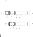
FIG. 9 illustrates anexemplary dispenser 900, not covered by the invention. Thedispenser 900 may be similar to the dispenser shown inFIGS. 1a-8 . In particular, it includes ahousing 902 and dispensingportion 908 that may be configured to be ejected/partially removed/entirely removed from an interior portion of thehousing 902. To remove the dispensingportion 908, thehousing 902 may include arotating portion 904 that may be configured to rotate in a direction A around vertical axis (i.e., axis parallel to the long side of the housing 902). Arod 907 may be configured to be disposed inside thehousing 902 and may be configured to be coupled (permanently, temporarily, etc.) to the dispensingportion 908 and therotating portion 904. Therod 907 may be configured to have one or more threads disposed thereon along extension of therod 907 that may allow it to be threaded in and out of therotating portion 904. Rotation of the portion 904 (e.g., in a clockwise direction A) may be configured to rotate or extend therod 907 and to push dispensingportion 908 out from the interior portion of the housing 902 (state 903). Rotation of theportion 904 in an opposite direction (e.g., counter-clockwise direction) may be configured to thread therod 907 in the corresponding direction and to pull the dispensingportion 908 into the interior portion of the housing 902 (state 901). As can be understood, any methods of pushing out or pulling in the dispensingportion 908 using therotating portion 904 are possible (e.g., using a screw, a piston, a push button, a spring, a tension-based mechanism, an elastic band, a telescoping rotation device, etc.). -
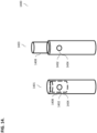
FIG. 10 illustrates anotherexemplary dispenser 1000, not covered by the invention. Thedispenser 1000 may be similar to the dispensers shown inFIGS. 1a-9 . In particular, it includes ahousing 1002 and dispensingportion 1008 that may be configured to be ejected/partially removed/entirely removed from an interior portion of thehousing 1002. To remove the dispensingportion 1008, thehousing 102 may include arotating portion 104 that may be configured to rotate in a direction A around vertical axis (i.e., axis parallel to the long side of the housing 1002). Theportion 1004 may be configured to be disposed substantially at an end of thedispenser 1000 that distal to the end of the dispensingportion 1008. Similar toFIG. 9 , rotation of the portion 1004 (e.g., in a clockwise direction A) may be configured to push dispensingportion 1008 out from the interior portion of the housing 1002 (state 1003). Rotation of theportion 1004 in an opposite direction (e.g., counter-clockwise direction) may be configured to pull the dispensingportion 1008 into the interior portion of the housing 1002 (state 1001). As can be understood, any methods of pushing out or pulling in the dispensingportion 1008 using the rotatingportion 1004 are possible (e.g., using a screw, a piston, a push button, a spring, a tension-based mechanism, an elastic band, etc.). In some implementations, the user may be configured to use a user's finger to push on theportion 1004, thereby causing the dispensingportion 1008 to be ejected/partially removed/entirely removed from the interior portion of thehousing 1002. To secure the dispensingportion 1008 inside thehousing 1002, the user may apply force to the top of the dispensingportion 1008, until it is entirely located within thehousing 1002. Any means of securing the dispensingportion 1008 may be used (e.g., hook(s), latch(es), ball-and-chain mechanism(s), etc.). -
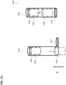
FIG. 11 illustrates yet anotherexemplary dispenser 1100, not covered by the invention. Thedispenser 1100 may be similar to the dispensers shown inFIGS. 1a-10 . In particular, it includes ahousing 1102 and dispensingportion 1108. The housing may also include acap 1104. Thecap 1104 may be configured to be entirely removable (e.g., state 1103), partially removable (e.g., thecap 1104 may be coupled to thehousing 1102 using a hinge, a spring-loaded hinge, a latch, etc.), etc. Thecap 1104 may be screw cap, twist on/off cap, snap on/off cap, push/pull cap, friction-fit cap, and/or any other type of cap. Thecap 1104 may be configured to conceal the dispensing portion 1108 (e.g., state 1101) when the dispensing portion is not in use. Alternatively, thecap 1104 may be configured to cover the top of thehousing 1102, while the dispensingportion 1108 is contained inside the interior portion of the housing 1102 (e.g., as shown inFIGS. 1a ,9-10 ). To use thedispenser 1100, the user may remove the cap 1104 (e.g., state 1103), e.g., by twisting the cap off, by unscrewing it, by pulling on it, etc., and then use the dispensingportion 1108. Alternatively, the dispensingportion 1108 may also be ejected or partially removed from the interior portion of thehousing 1102. Any means of securing and/or removing thecap 1104 to/from thehousing 1102 may be used. -
FIG. 12 illustrates yet anotherexemplary dispenser 1200, not covered by the invention. Thedispenser 1200 may be similar to thedispenser 1100 shown inFIG. 11 . Thedispenser 1200 may include ahousing 1202 and dispensingportion 1208. The housing may also include a flip cover and/or a hingedcover 1204. Thecover 1204 may be configured to be hingedly coupled to thehousing 1202 and may be configured to be opened (state 1203) and closed (state 1201) using, for example, ahinge 1207 Once thecover 1204 is opened (state 1203), i.e., rotated about thehinge 1207, the dispensingportion 1208 may be exposed (alternatively, the user may need to eject or partially remove the dispensingportion 1208, as discussed above) and the user may use thedispenser 1200 for flossing as discussed above. Any means of securing and/or removing thecover 1204 to/from thehousing 1202 may be used. -
FIG. 13 illustrates yet anotherexemplary dispenser 1300, not covered by the invention. Thedispenser 1300 may be similar to the dispenser shown inFIG. 11 . In particular, it includes ahousing 1302 and dispensingportion 1308. The housing may also include a slidingcover 1304. Thecover 1304 may be configured to be slide along an outer surface of thehousing 1302 for the purposes of concealing the dispensing portion 1308 (e.g., state 1301) and exposing the dispensing portion 1308 (e.g., state 1303). Thecover 1304 may slide on rails, roller balls, gears, etc. Alternatively, the slidingcover 1304 may be threaded on/off for the purposes of concealing/exposing the dispensingportion 1308. Thecover 1304 may be configured to cover the top of the housing 1302 (similar toFIG. 11 ), while the dispensingportion 1308 is contained inside the interior portion of the housing 1302 (e.g., as shown inFIGS. 1a ,9-11 ). To use thedispenser 1300, the user may slide thecover 1304 down (e.g., state 1303) and then use the dispensingportion 1308. Alternatively, the dispensingportion 1308 may also be ejected or partially removed from the interior portion of thehousing 1302. Any means of securing and/or removing thecover 1304 to/from thehousing 1302 may be used. -
FIG. 14 illustrates yet anotherexemplary dispenser 1400, not covered by the invention. Thedispenser 1400 may be similar to the dispensers shown inFIG. 1a-13 . Thedispenser 1400 may include ahousing 1402 and dispensingportion 1408, as discussed above. Thehousing 1402 may also include abutton 1404. The button may be used to eject or partially remove (state 1403) and/or conceal (state 1401) thedispensing portion 1408 from and/or into the interior portion of thehousing 1402. Once thebutton 1404 is pressed, the dispensingportion 1408 may slide inside thehousing 1402; upon pressing thebutton 1404 the next time, the dispensingportion 1408 may slide out of thehousing 1402. Thebutton 1404 may be coupled to a mechanical, electrical, electronic, electro-mechanical and/or any combination thereof, mechanism that may trigger movement of the dispensingportion 1408. -
FIG. 15 illustrates an exemplary process for loading a dispenser 1500 (similar to dispensers shown inFIGS. 1a-14 ) with adental floss 1504, according to some implementations of the current subject matter. As shown inFIG. 15 , thedental floss 1504 may be loaded into thehousing 1502 from the bottom of thehousing 1502. In particular, to load thedental floss 1504, abottom portion 1507 may be opened (state 1501) and thedental floss 1504 may be inserted in an upward direction (i.e., direction A). Once thedental floss 1504 has been loaded into thehousing 1502, thebottom portion 1507 may be closed (state 1503). As can be understood, thebottom portion 1507 may be hingedly coupled to thehousing 1502, may be entirely removable from thehousing 1502, may be snapped on/off thehousing 1502, may be clipped on/off thehousing 1502, and/or otherwise coupled to the housing in any desired way. -
FIG. 16 illustrates an exemplary process for loading a dispenser 1600 (similar to dispensers shown inFIGS. 1a-14 ) with adental floss 1604, not covered by the invention. Thehousing 1602 of thedispenser 1600 may include anaccess structure 1607. Thestructure 1607 may be a single or a double side door, a vertical clam-shell structure, a horizontal clam-shell structure, and/or any other structure that may allow positioning of thedental floss 1604 inside theinterior portion 1602 of thedispenser 1600. As, for example, is shown inFIG. 16 , thehousing 1602 may include a vertical clam-shell structure 1607 that may be configured to allow opening (e.g., rotation in directions B and C) on of thehousing 1602 to expose the interior portion of thehousing 1602. Once the interior is exposed, thedental floss 1604 may be placed inside the housing 1602 (e.g., as shown by direction A) and the clam-shell structure 1607 may be closed (state 1603), thereby concealing the interior portion of thehousing 1602. As can be understood, theaccess structure 1607 may include at least one of the following: one or more hinges, one or more locks, one more hooks, one or more snaps, and/or any other mechanisms. - In some implementations, the housing of the dispenser (e.g., dispenser shown in
FIGS. 1a-17e ) may include storage space that may allow storage of various items, such as, but not limited to, toothpaste, toothpicks, floss picks, medication, toothbrush head(s), money, food, etc. The space may accessed using any of the means discussed above. In some exemplary implementations, the dispensingportion 108, 308 (e.g., as shown inFIGS. 1 ,3a-c ) may be substituted for and/or replaced with a toothbrush and/or any other device. For example, the dispensingportion portion portion -
FIGS. 17a-e illustrates an exemplary dental floss supporting/stabilization structure 1702, not covered by the invention. In some exemplary implementations, thestructure 1702 may be used for securing/stabilizing the wound string of dental floss 604 (e.g., a bobbin, a roll, etc.), as shown inFIG. 6 . Thestructure 1702 may be configured to wrap the wound string ofdental floss 604, thereby improving dispensing of the dental floss from the dental floss dispenser shown inFIGS. 1a-16 , preventing tangling of dental floss string, etc. - As shown in
FIGS. 17a-e , to secure the wound string ofdental floss 604, a cover 1712 (e.g., a rubber disk, a pill, etc.) and thesupport structure 1702 may be used. Thecover 1712 may include aslit 1710 that may be used for threading astring 320 of the dental floss. Thecover 1712 may be placed on top of the bobbin 604 (as shown inFIG. 17e ). The bobbin may be configured to be coreless, e.g., there is no core (e.g., paper, plastic, etc.) structure in the center of the bobbin, whereby the dental floss may unwind from the center of the bobbin rather than from the outside. As can be understood, the floss may be configured to unwind from any location on the bobbin. In some exemplary, non-limiting implementations, the wound string of dental floss (or a refill of dental floss) may be configured as acylindrical bobbin 604. As can be understood, thebobbin 604 may have various shapes, sizes, lengths of floss wrapped in, thickness of floss, etc. - The
support structure 1702 may be configured as a wrap that may include an adhesive backing disposed on one side of thestructure 1702. The adhesive may be safe for use with the dental floss, and thus, safe for use for the user. The support structure may be wrapped around thebobbin 604. The support structure may includetabs tabs structure 1702, as shown inFIG. 17a . Thetabs structures having spaces spaces cover 1712, as shown inFIG. 17b . Theprong structures FIG. 17a , and may be configured to include an adhesive backing. - As shown in
FIGS. 17c-e , thestructure 1702 may be adhesively coupled to thebobbin 604, with theprongs slit 1710 of thecover 1712. Once thestructure 1702 is coupled to thebobbin 604, thebobbin 604 may be rotated in a direction A (as shown inFIG. 17d ) to wrap thestructure 1702 around thebobbin 604. Alternatively, or in addition to, thestructure 1702 may be wrapped around thebobbin 604 without rotating thebobbin 604. Upon wrapping thestructure 1702 around thebobbin 604, thetab 1704 may be lowered on top of the cover 312 (thetab 1704 may include an adhesive backing and thus, be adhesively coupled to the cover 312). Thesecond tab 1706 may be placed on top of thefirst tab 1704, as shown inFIGS. 17b and17e . In some exemplary implementations, thetab 1706 may be without any adhesive backing, which may assist the user of the dental floss dispenser in easily removing the spent dental floss refill by simply pulling on thetab 1706. - After the bobbin is wound, the dispensing
end 702 of thedental floss 320 may be threaded through theslit 1712 in thecover 1710. Thecover 1710 along with theslit 1712 may provide a friction drag onto thedental floss 320 as it is dispensed to prevent thedental floss 320 from dispensing unintentionally and may further provide tension on thedental floss 320 which may assist during the floss cutting process. After threading through theslit 1710, thebobbin 604 andcover 1712 may be wrapped together by rolling theadhesive structure 1702 around the bobbin and the cover. This may ensure that the surface of thebobbin 604 is adhered to thestructure 1702. Theadhesive structure 1702'stabs cover 1712 to be securely fastened to thebobbin 604 while allowing thedental floss 320 to pass freely through theslit 1710. After thebobbin 604 is assembled with the cover and thestructure 1702, the dispensing end of the dental floss may be rigidized (e.g., using a wax coating 702) to allow the user to easily thread that end into the dispenser device. Further, in some implementations, thestructure 1702 may provide a rigid structure for the outer windings of floss in thefloss bobbin 604, where such windings may be configured to adhere to thestructure 1702. Absent thestructure 1702, thebobbin 604 may collapse inwards and/or may cause tangling and/or knotting of the dental floss. Moreover, thestructure 1702 may allow the full length of thebobbin 604 to be dispensed without knotting and/or tangling. - To remove an expended refill from the dispenser device, the user may remove the cap portion of the dispenser device, grasp the
loose tabs 1704 and/or 1706 from the refill, and pull the empty adhesive wrap out of the dispenser device to thereby remove the adhered cover simultaneously. To refill the device after removing an expended refill, the user may place thenew bobbin 604 into the dispenser device with the dispensing end of the floss pointed upwards. The user may then thread the rigidized portion of dental floss through the cap of the dispenser device, replace the cap to the dispenser device, and press down firmly until the cap "clicks" into place. - As can be understood the shapes and/or sizes of any components of the dispenser are not limited to those shown in
FIGS. 1a-17e . The dispenser and/or any of its components may have cylindrical shape(s), cubical shape(s), circular shape(s), square shape(s), rectangular shape(s), irregular shape(s), and/or any other shapes. - The dental floss dispenser may include a
dispenser housing 102 enclosing an interior portion and a dispensingportion 108 slidably positioned inside the interior portion of the dispenser housing. The dispensingportion 108 may have a stored position (e.g., as shown inFIGS. 1a-b ) and a dispensing position (e.g., as shown inFIGS. 3a-c ). In the stored position, the dispensing portion may be entirely disposed in the interior portion. In the dispensing position, the dispensing portion may be partially disposed outside of the interior portion. The dispensing portion may further include a storage chamber (e.g., floss housing 402) for storing a wound string of dental floss (e.g., dental floss 604) and a floss dispensing cavity (e.g., floss holding section 306) for holding at least a portion of the wound string of dental floss extracted from the storage chamber. - The dental floss dispenser may further include a locking mechanism (e.g., as shown in
FIGS. 4 and8 ) configured to temporarily retain the dispensing portion in the stored position or the dispensing position. The locking mechanism may include a spring component (e.g., spring 404) and a latching component (e.g., latchportions - The dispensing portion may be configured to be entirely removable from the interior portion of the dispenser housing (e.g., as shown in
FIGS. 4 and6 ). The wound string of dental floss may be configured to be removable from the storage chamber upon entire removal of the dispensing portion from the interior portion of the dispenser housing. The wound string of dental floss may be configured to be wound in a coreless manner (e.g., without a core structure). A support structure (e.g., wrap 1702 shown inFIGS. 17a-e ) may be configured to wrap the wound string of dental floss. The support structure may be configured to adhesively wrap the wound string of dental floss. The wound string of dental floss may be further configured to unwind from an interior of the wound string of dental floss. The wound string of dental floss may be configured to have one or more exterior dimensions smaller than one or more interior dimensions of the storage chamber. The wound string of dental floss may include a laminated end (e.g., end 702). The wound string of dental floss may be configured to be wound in at least one of the following shapes: a cylinder, a tube, a roll, a torus, a sphere, a cone, a prism, an ellipsoid, a helix, and any combination thereof. - The dispensing portion may include a concave open cavity (e.g., cavity 308) having a top 311 and a bottom 313, a
first opening 304 disposed in the bottom and configured for protruding the portion of the wound string of dental floss from the storage chamber, and asecond opening 315 disposed in the top and configured for holding the protruded portion of the wound string of dental floss. The second opening of the concave open cavity may include a cutting mechanism (e.g., cutting mechanism 502) for cutting the dental floss. - The dispenser housing may include a stopping mechanism (e.g., lip 418) disposed in the interior portion proximate to a top of the dispenser housing. The dispensing portion may include one or more protrusions (e.g., protrusions 416) disposed on an exterior surface of the dispensing portion. The stopping mechanism may be configured to interact with one or more protrusions to temporarily prevent removal of the dispensing portion from the interior portion of the dispenser housing.
- The storage chamber may be configured to be interlocked with the floss dispensing cavity for holding the wound string of dental floss (e.g., as shown in
FIG. 6 ). -
FIG. 18 illustrates anexemplary method 1800 for loading the dental floss dispenser with a dental floss. At 1802, the dental floss dispenser, as described above, may be provided. At 1804, the dispensing portion may be removed from the interior portion of the dispenser housing. At 1806, the wound string of dental floss may be inserted into the storage chamber. At 1808, at least a portion of the wound string of dental floss may be extracted from the storage chamber and the extracted portion of the wound string of dental floss may be positioned across the floss dispensing cavity (e.g., as shown inFIG. 3c ). At 1810, the dispensing portion may be placed into the interior portion of the dispenser housing. -
FIG. 19 illustrates anexemplary method 1900 for using the dental floss dispenser described above. Themethod 1900 may include providing the dental floss dispenser, as described above, at 1902. At 1904, the dispensing portion may be partially removed from the interior portion of the dispenser housing. At 1906, at least a portion of dental floss may be extracted from the storage chamber and the extracted portion may be secured to the floss dispensing cavity. At 1908, the dental floss dispenser may be used for flossing. At 1910, the dispensing portion may be placed into the interior portion of the dispenser housing.
Claims (13)
- A dental floss dispenser (100), comprising:a dispenser housing (102) enclosing an interior portion (118); anda dispensing portion (108) slidably positioned inside the interior portion (118) of the dispenser housing (102),the dispensing portion having a stored position and a dispensing position, wherein, in the stored position, the dispensing portion is entirely disposed in the interior portion, and, in the dispensing position, the dispensing portion is partially disposed outside of the interior portion;the dispensing portion (108) including a storage chamber (402) for storing a wound string of dental floss (604) and a floss dispensing cavity (306) for holding at least a portion of the wound string of dental floss (604) extracted from the storage chamber; anda locking mechanism configured to temporarily retain the dispensing portion (108) in stored position or the dispensing position wherein the locking mechanism including a spring component (404) and a latching component (414,412,408), wherein the spring component (404), upon unlocking of the latching component (414,412,408), is configured to position the dispensing portion (108) in the dispensing position, and the latching component (414,412,408), upon locking, is configured to retain the dispensing portion (108) in the stored position.
- The dental floss dispenser according to claim 1, wherein the dispensing portion is entirely removable from the interior portion of the dispenser housing.
- The dental floss dispenser according to claim 2, wherein the wound string of dental floss is removable from the storage chamber upon entire removal of the dispensing portion from the interior portion of the dispenser housing.
- The dental floss dispenser according to claim 3, wherein the wound string of dental floss is coreless.
- The dental floss dispenser according to claim 4, further comprising a support structure wrapped about the wound string of dental floss.
- The dental floss dispenser according to claim 5, wherein the support structure is adhesively wrapped about the wound string of dental floss.
- The dental floss dispenser according to any of claims 4 to 6, wherein the wound string of dental floss unwindable from an interior of the wound string of dental floss.
- The dental floss dispenser according to any of claims 4 to 7, wherein the wound string of dental floss has one or more exterior dimensions smaller than one or more interior dimensions of the storage chamber.
- The dental floss dispenser according to any of claims 4 to 8, wherein the wound string of dental floss (604) includes a laminated end (702).
- The dental floss dispenser according to any of claims 4 to 9, wherein the wound string of dental floss in at least one of the following shapes: a cylinder, a tube, a roll, a torus, a sphere, a cone, a prism, an ellipsoid, a helix, and any combination thereof.
- The dental floss dispenser according to any of the previous claims, wherein the dispensing portion (108) includesa concave open cavity (308) having a top and a bottom,a first opening (304) defined in the bottom , the portion of the wound string of dental floss extendable through the first opening from the storage chamber, anda second opening (114,315) defined in the top , the protruded portion of the wound string of dental floss extendable through the second opening.
- The dental floss dispenser according to claim 11, wherein the second opening (114,315) of the concave open cavity includes a cutting mechanism (110) for cutting the dental floss.
- The dental floss dispenser according to any of the previous claims, wherein the storage chamber interlockable with the floss dispensing cavity for holding the wound string of dental floss.
Priority Applications (1)
| Application Number | Priority Date | Filing Date | Title |
|---|---|---|---|
| EP24218873.8A EP4529885A3 (en) | 2019-09-16 | 2020-09-10 | Dental floss dispenser |
Applications Claiming Priority (2)
| Application Number | Priority Date | Filing Date | Title |
|---|---|---|---|
| US201962900930P | 2019-09-16 | 2019-09-16 | |
| PCT/US2020/070519 WO2021056011A1 (en) | 2019-09-16 | 2020-09-10 | Dental floss dispenser |
Related Child Applications (1)
| Application Number | Title | Priority Date | Filing Date |
|---|---|---|---|
| EP24218873.8A Division EP4529885A3 (en) | 2019-09-16 | 2020-09-10 | Dental floss dispenser |
Publications (4)
| Publication Number | Publication Date |
|---|---|
| EP4031061A1 EP4031061A1 (en) | 2022-07-27 |
| EP4031061A4 EP4031061A4 (en) | 2023-09-13 |
| EP4031061C0 EP4031061C0 (en) | 2024-12-11 |
| EP4031061B1 true EP4031061B1 (en) | 2024-12-11 |
Family
ID=74884254
Family Applications (2)
| Application Number | Title | Priority Date | Filing Date |
|---|---|---|---|
| EP24218873.8A Pending EP4529885A3 (en) | 2019-09-16 | 2020-09-10 | Dental floss dispenser |
| EP20865764.3A Active EP4031061B1 (en) | 2019-09-16 | 2020-09-10 | Dental floss dispenser |
Family Applications Before (1)
| Application Number | Title | Priority Date | Filing Date |
|---|---|---|---|
| EP24218873.8A Pending EP4529885A3 (en) | 2019-09-16 | 2020-09-10 | Dental floss dispenser |
Country Status (5)
| Country | Link |
|---|---|
| US (1) | US20220257354A1 (en) |
| EP (2) | EP4529885A3 (en) |
| CN (1) | CN115279299B (en) |
| CA (1) | CA3151105A1 (en) |
| WO (1) | WO2021056011A1 (en) |
Families Citing this family (1)
| Publication number | Priority date | Publication date | Assignee | Title |
|---|---|---|---|---|
| GB2607929A (en) * | 2021-06-16 | 2022-12-21 | Flush Health Ltd | Floss dispenser |
Family Cites Families (14)
| Publication number | Priority date | Publication date | Assignee | Title |
|---|---|---|---|---|
| US1646082A (en) * | 1927-01-28 | 1927-10-18 | Johnson & Johnson | Toothbrush |
| US3246815A (en) * | 1964-09-02 | 1966-04-19 | Woltra Company Inc | Dental floss dispenser |
| US4005721A (en) * | 1975-03-17 | 1977-02-01 | Michio Yasumoto | Dental floss holder |
| US5718251A (en) * | 1996-04-26 | 1998-02-17 | W. L. Gore & Associates, Inc. | Dental floss article |
| US5899214A (en) * | 1998-02-06 | 1999-05-04 | Francis; Shlomo | Dental floss dispenser and applicator used in fixed orthodontic appliances |
| US6398093B1 (en) * | 1999-04-16 | 2002-06-04 | Gore Enterprise Holdings, Inc. | Cutting device for dental floss |
| US6295997B1 (en) * | 2000-07-25 | 2001-10-02 | Spark Innovations Inc. | Dispenser for dental floss |
| US20040119297A1 (en) * | 2002-12-24 | 2004-06-24 | Bella Joseph J. | Push-push sliding cosmetic container |
| US8015982B2 (en) * | 2004-10-26 | 2011-09-13 | Wilkinson William T | Toothbrush and flossing system |
| US7198051B1 (en) * | 2005-11-08 | 2007-04-03 | Antonio Festa | Combination toothbrush-dental floss dispenser |
| US20070209953A1 (en) * | 2006-03-31 | 2007-09-13 | Frank Conte | Dental Floss Dispensing Device |
| GB2494928B (en) * | 2011-09-26 | 2013-10-09 | Rashid Zlaoui | Oral hygiene apparatus |
| US9078724B2 (en) * | 2013-07-08 | 2015-07-14 | Jeremy Angelo Devins | Dental floss apparatus |
| US20180279764A1 (en) * | 2017-03-29 | 2018-10-04 | Gerald Hill | Combination toothbrush and dental floss dispenser |
-
2020
- 2020-09-10 CA CA3151105A patent/CA3151105A1/en active Pending
- 2020-09-10 EP EP24218873.8A patent/EP4529885A3/en active Pending
- 2020-09-10 EP EP20865764.3A patent/EP4031061B1/en active Active
- 2020-09-10 WO PCT/US2020/070519 patent/WO2021056011A1/en not_active Ceased
- 2020-09-10 CN CN202080077840.1A patent/CN115279299B/en active Active
-
2022
- 2022-03-09 US US17/690,079 patent/US20220257354A1/en active Pending
Also Published As
| Publication number | Publication date |
|---|---|
| EP4529885A2 (en) | 2025-04-02 |
| CN115279299A (en) | 2022-11-01 |
| US20220257354A1 (en) | 2022-08-18 |
| CA3151105A1 (en) | 2021-03-25 |
| EP4031061A1 (en) | 2022-07-27 |
| EP4031061C0 (en) | 2024-12-11 |
| EP4529885A3 (en) | 2025-07-23 |
| WO2021056011A1 (en) | 2021-03-25 |
| CN115279299B (en) | 2025-01-10 |
| EP4031061A4 (en) | 2023-09-13 |
Similar Documents
| Publication | Publication Date | Title |
|---|---|---|
| US5762281A (en) | Automatically loading cord winder apparatus and method | |
| US5630563A (en) | Apparatus for dispensing a controlled length of sheet material from a roll | |
| EP0026319B1 (en) | Dispensing device for articles | |
| CN103140187B (en) | flossing system | |
| US4336097A (en) | Dispenser for liner-wound tape | |
| EP2363079B1 (en) | Suture loading package | |
| US5860561A (en) | Cotton swab dispenser | |
| US8272389B2 (en) | Compact mirror floss container | |
| US4934389A (en) | Dental floss dispenser | |
| AU732935B2 (en) | Dental floss container | |
| JPH0355054A (en) | Dental floss holder | |
| US9016287B2 (en) | Dental flossing device | |
| JP4795229B2 (en) | Dental hygiene equipment | |
| US9926169B2 (en) | Universal winder | |
| US20220257354A1 (en) | Dental floss dispenser | |
| US4330357A (en) | Dispenser for liner-wound tape | |
| US9643814B2 (en) | Universal winder | |
| US20090188519A1 (en) | Toothbrush with dental floss holder | |
| USRE32010E (en) | Dispenser for liner-wound tape | |
| US20120111349A1 (en) | Oral Hygiene Apparatuses and Methods | |
| US20050035134A1 (en) | Wipe dispenser threader | |
| US20140290691A1 (en) | Dental Tape and Floss Holder With Installation Cassette | |
| US7213604B2 (en) | Dental flossing tool and dispenser | |
| US3804102A (en) | Dental floss dispenser | |
| KR101634062B1 (en) | dental floss holder |
Legal Events
| Date | Code | Title | Description |
|---|---|---|---|
| STAA | Information on the status of an ep patent application or granted ep patent |
Free format text: STATUS: THE INTERNATIONAL PUBLICATION HAS BEEN MADE |
|
| PUAI | Public reference made under article 153(3) epc to a published international application that has entered the european phase |
Free format text: ORIGINAL CODE: 0009012 |
|
| STAA | Information on the status of an ep patent application or granted ep patent |
Free format text: STATUS: REQUEST FOR EXAMINATION WAS MADE |
|
| 17P | Request for examination filed |
Effective date: 20220310 |
|
| AK | Designated contracting states |
Kind code of ref document: A1 Designated state(s): AL AT BE BG CH CY CZ DE DK EE ES FI FR GB GR HR HU IE IS IT LI LT LU LV MC MK MT NL NO PL PT RO RS SE SI SK SM TR |
|
| DAV | Request for validation of the european patent (deleted) | ||
| DAX | Request for extension of the european patent (deleted) | ||
| A4 | Supplementary search report drawn up and despatched |
Effective date: 20230817 |
|
| RIC1 | Information provided on ipc code assigned before grant |
Ipc: A61C 15/04 20060101AFI20230810BHEP |
|
| GRAP | Despatch of communication of intention to grant a patent |
Free format text: ORIGINAL CODE: EPIDOSNIGR1 |
|
| STAA | Information on the status of an ep patent application or granted ep patent |
Free format text: STATUS: GRANT OF PATENT IS INTENDED |
|
| INTG | Intention to grant announced |
Effective date: 20240709 |
|
| GRAS | Grant fee paid |
Free format text: ORIGINAL CODE: EPIDOSNIGR3 |
|
| GRAA | (expected) grant |
Free format text: ORIGINAL CODE: 0009210 |
|
| STAA | Information on the status of an ep patent application or granted ep patent |
Free format text: STATUS: THE PATENT HAS BEEN GRANTED |
|
| AK | Designated contracting states |
Kind code of ref document: B1 Designated state(s): AL AT BE BG CH CY CZ DE DK EE ES FI FR GB GR HR HU IE IS IT LI LT LU LV MC MK MT NL NO PL PT RO RS SE SI SK SM TR |
|
| REG | Reference to a national code |
Ref country code: GB Ref legal event code: FG4D |
|
| REG | Reference to a national code |
Ref country code: CH Ref legal event code: EP |
|
| REG | Reference to a national code |
Ref country code: IE Ref legal event code: FG4D |
|
| REG | Reference to a national code |
Ref country code: DE Ref legal event code: R096 Ref document number: 602020043119 Country of ref document: DE |
|
| U01 | Request for unitary effect filed |
Effective date: 20250108 |
|
| U07 | Unitary effect registered |
Designated state(s): AT BE BG DE DK EE FI FR IT LT LU LV MT NL PT RO SE SI Effective date: 20250116 |
|
| PG25 | Lapsed in a contracting state [announced via postgrant information from national office to epo] |
Ref country code: HR Free format text: LAPSE BECAUSE OF FAILURE TO SUBMIT A TRANSLATION OF THE DESCRIPTION OR TO PAY THE FEE WITHIN THE PRESCRIBED TIME-LIMIT Effective date: 20241211 |
|
| PG25 | Lapsed in a contracting state [announced via postgrant information from national office to epo] |
Ref country code: ES Free format text: LAPSE BECAUSE OF FAILURE TO SUBMIT A TRANSLATION OF THE DESCRIPTION OR TO PAY THE FEE WITHIN THE PRESCRIBED TIME-LIMIT Effective date: 20241211 |
|
| PG25 | Lapsed in a contracting state [announced via postgrant information from national office to epo] |
Ref country code: NO Free format text: LAPSE BECAUSE OF FAILURE TO SUBMIT A TRANSLATION OF THE DESCRIPTION OR TO PAY THE FEE WITHIN THE PRESCRIBED TIME-LIMIT Effective date: 20250311 |
|
| PG25 | Lapsed in a contracting state [announced via postgrant information from national office to epo] |
Ref country code: GR Free format text: LAPSE BECAUSE OF FAILURE TO SUBMIT A TRANSLATION OF THE DESCRIPTION OR TO PAY THE FEE WITHIN THE PRESCRIBED TIME-LIMIT Effective date: 20250312 |
|
| PG25 | Lapsed in a contracting state [announced via postgrant information from national office to epo] |
Ref country code: RS Free format text: LAPSE BECAUSE OF FAILURE TO SUBMIT A TRANSLATION OF THE DESCRIPTION OR TO PAY THE FEE WITHIN THE PRESCRIBED TIME-LIMIT Effective date: 20250311 |
|
| PG25 | Lapsed in a contracting state [announced via postgrant information from national office to epo] |
Ref country code: SM Free format text: LAPSE BECAUSE OF FAILURE TO SUBMIT A TRANSLATION OF THE DESCRIPTION OR TO PAY THE FEE WITHIN THE PRESCRIBED TIME-LIMIT Effective date: 20241211 |
|
| PG25 | Lapsed in a contracting state [announced via postgrant information from national office to epo] |
Ref country code: PL Free format text: LAPSE BECAUSE OF FAILURE TO SUBMIT A TRANSLATION OF THE DESCRIPTION OR TO PAY THE FEE WITHIN THE PRESCRIBED TIME-LIMIT Effective date: 20241211 |
|
| PG25 | Lapsed in a contracting state [announced via postgrant information from national office to epo] |
Ref country code: IS Free format text: LAPSE BECAUSE OF FAILURE TO SUBMIT A TRANSLATION OF THE DESCRIPTION OR TO PAY THE FEE WITHIN THE PRESCRIBED TIME-LIMIT Effective date: 20250411 |
|
| PG25 | Lapsed in a contracting state [announced via postgrant information from national office to epo] |
Ref country code: SK Free format text: LAPSE BECAUSE OF FAILURE TO SUBMIT A TRANSLATION OF THE DESCRIPTION OR TO PAY THE FEE WITHIN THE PRESCRIBED TIME-LIMIT Effective date: 20241211 |
|
| PG25 | Lapsed in a contracting state [announced via postgrant information from national office to epo] |
Ref country code: CZ Free format text: LAPSE BECAUSE OF FAILURE TO SUBMIT A TRANSLATION OF THE DESCRIPTION OR TO PAY THE FEE WITHIN THE PRESCRIBED TIME-LIMIT Effective date: 20241211 |
|
| PLBE | No opposition filed within time limit |
Free format text: ORIGINAL CODE: 0009261 |
|
| STAA | Information on the status of an ep patent application or granted ep patent |
Free format text: STATUS: NO OPPOSITION FILED WITHIN TIME LIMIT |
|
| REG | Reference to a national code |
Ref country code: CH Ref legal event code: L10 Free format text: ST27 STATUS EVENT CODE: U-0-0-L10-L00 (AS PROVIDED BY THE NATIONAL OFFICE) Effective date: 20251022 |
|
| U20 | Renewal fee for the european patent with unitary effect paid |
Year of fee payment: 6 Effective date: 20250929 |
|
| 26N | No opposition filed |
Effective date: 20250912 |
|
| REG | Reference to a national code |
Ref country code: CH Ref legal event code: H13 Free format text: ST27 STATUS EVENT CODE: U-0-0-H10-H13 (AS PROVIDED BY THE NATIONAL OFFICE) Effective date: 20260504 |