EP4030709A1 - Methods and apparatuses for communication - Google Patents
Methods and apparatuses for communication Download PDFInfo
- Publication number
- EP4030709A1 EP4030709A1 EP21152216.4A EP21152216A EP4030709A1 EP 4030709 A1 EP4030709 A1 EP 4030709A1 EP 21152216 A EP21152216 A EP 21152216A EP 4030709 A1 EP4030709 A1 EP 4030709A1
- Authority
- EP
- European Patent Office
- Prior art keywords
- output
- input
- processing stages
- data stream
- configuration
- Prior art date
- Legal status (The legal status is an assumption and is not a legal conclusion. Google has not performed a legal analysis and makes no representation as to the accuracy of the status listed.)
- Granted
Links
Images


Classifications
-
- H—ELECTRICITY
- H04—ELECTRIC COMMUNICATION TECHNIQUE
- H04L—TRANSMISSION OF DIGITAL INFORMATION, e.g. TELEGRAPHIC COMMUNICATION
- H04L47/00—Traffic control in data switching networks
- H04L47/50—Queue scheduling
- H04L47/58—Changing or combining different scheduling modes, e.g. multimode scheduling
-
- H—ELECTRICITY
- H04—ELECTRIC COMMUNICATION TECHNIQUE
- H04W—WIRELESS COMMUNICATION NETWORKS
- H04W28/00—Network traffic management; Network resource management
- H04W28/02—Traffic management, e.g. flow control or congestion control
- H04W28/06—Optimizing the usage of the radio link, e.g. header compression, information sizing, discarding information
-
- H—ELECTRICITY
- H04—ELECTRIC COMMUNICATION TECHNIQUE
- H04W—WIRELESS COMMUNICATION NETWORKS
- H04W28/00—Network traffic management; Network resource management
- H04W28/02—Traffic management, e.g. flow control or congestion control
- H04W28/0231—Traffic management, e.g. flow control or congestion control based on communication conditions
- H04W28/0236—Traffic management, e.g. flow control or congestion control based on communication conditions radio quality, e.g. interference, losses or delay
-
- H—ELECTRICITY
- H04—ELECTRIC COMMUNICATION TECHNIQUE
- H04L—TRANSMISSION OF DIGITAL INFORMATION, e.g. TELEGRAPHIC COMMUNICATION
- H04L41/00—Arrangements for maintenance, administration or management of data switching networks, e.g. of packet switching networks
- H04L41/08—Configuration management of networks or network elements
- H04L41/0803—Configuration setting
- H04L41/0823—Configuration setting characterised by the purposes of a change of settings, e.g. optimising configuration for enhancing reliability
-
- H—ELECTRICITY
- H04—ELECTRIC COMMUNICATION TECHNIQUE
- H04L—TRANSMISSION OF DIGITAL INFORMATION, e.g. TELEGRAPHIC COMMUNICATION
- H04L41/00—Arrangements for maintenance, administration or management of data switching networks, e.g. of packet switching networks
- H04L41/08—Configuration management of networks or network elements
- H04L41/0803—Configuration setting
- H04L41/0823—Configuration setting characterised by the purposes of a change of settings, e.g. optimising configuration for enhancing reliability
- H04L41/0836—Configuration setting characterised by the purposes of a change of settings, e.g. optimising configuration for enhancing reliability to enhance reliability, e.g. reduce downtime
-
- H—ELECTRICITY
- H04—ELECTRIC COMMUNICATION TECHNIQUE
- H04L—TRANSMISSION OF DIGITAL INFORMATION, e.g. TELEGRAPHIC COMMUNICATION
- H04L45/00—Routing or path finding of packets in data switching networks
- H04L45/24—Multipath
- H04L45/245—Link aggregation, e.g. trunking
-
- H—ELECTRICITY
- H04—ELECTRIC COMMUNICATION TECHNIQUE
- H04L—TRANSMISSION OF DIGITAL INFORMATION, e.g. TELEGRAPHIC COMMUNICATION
- H04L47/00—Traffic control in data switching networks
- H04L47/50—Queue scheduling
- H04L47/62—Queue scheduling characterised by scheduling criteria
- H04L47/6205—Arrangements for avoiding head of line blocking
-
- H—ELECTRICITY
- H04—ELECTRIC COMMUNICATION TECHNIQUE
- H04L—TRANSMISSION OF DIGITAL INFORMATION, e.g. TELEGRAPHIC COMMUNICATION
- H04L47/00—Traffic control in data switching networks
- H04L47/70—Admission control; Resource allocation
- H04L47/72—Admission control; Resource allocation using reservation actions during connection setup
- H04L47/726—Reserving resources in multiple paths to be used simultaneously
-
- H—ELECTRICITY
- H04—ELECTRIC COMMUNICATION TECHNIQUE
- H04W—WIRELESS COMMUNICATION NETWORKS
- H04W28/00—Network traffic management; Network resource management
- H04W28/02—Traffic management, e.g. flow control or congestion control
- H04W28/08—Load balancing or load distribution
- H04W28/082—Load balancing or load distribution among bearers or channels
-
- H—ELECTRICITY
- H04—ELECTRIC COMMUNICATION TECHNIQUE
- H04W—WIRELESS COMMUNICATION NETWORKS
- H04W28/00—Network traffic management; Network resource management
- H04W28/02—Traffic management, e.g. flow control or congestion control
- H04W28/08—Load balancing or load distribution
- H04W28/09—Management thereof
- H04W28/0958—Management thereof based on metrics or performance parameters
- H04W28/0967—Quality of Service [QoS] parameters
-
- H—ELECTRICITY
- H04—ELECTRIC COMMUNICATION TECHNIQUE
- H04L—TRANSMISSION OF DIGITAL INFORMATION, e.g. TELEGRAPHIC COMMUNICATION
- H04L47/00—Traffic control in data switching networks
- H04L47/10—Flow control; Congestion control
- H04L47/12—Avoiding congestion; Recovering from congestion
- H04L47/125—Avoiding congestion; Recovering from congestion by balancing the load, e.g. traffic engineering
Definitions
- wireless communication systems require lower latency and higher reliability in order to support emerging applications like industrial control, mobile robotics and V2X-services.
- a measure to enhance the latency and reliability performance of wireless communication systems is Multi- Connectivity (MC) where multiple communication paths are used at the same time.
- MC Multi- Connectivity
- Examples for already existing MC systems are MP-TCP on Transport Layer or Dual Connectivity in 3GPP that can be utilized to enhance the throughput or improve the latency and reliability of the system.
- the existing MC schemes all offer the option to use a single scheduling scheme over two or multiple paths.
- PD Packet Duplication
- LB Load Balancing
- a method comprises: receiving or determining an input data stream; propagating the input data stream through a plurality of consecutive input processing stages, wherein the input data stream is provided at an input section of the consecutive input processing stages, wherein a plurality of output data streams is provided at an output section of the plurality of consecutive input processing stages, wherein the plurality of input processing stages comprise an increasing number of processing units per processing stage in the direction of the output section, wherein the respective processing unit determines a plurality of output streams based on its input data stream and based on a scheduling scheme that is associated with the respective input processing stage, and wherein the scheduling schemes differ from each other at least between adjacent input processing stages; and transmitting the plurality of output data streams provided at the output section via a plurality of communication channels.
- the performance of data communication is increased with respect to efficiency, latency and reliability of the provided multi-connectivity scheduling schemes in the presence of multiple links or communication channels.
- the method further comprises: receiving or determining a configuration for the input processing stages, wherein the configuration comprises at least a plurality of associations between one of the input processing stages and one of the plurality of scheduling schemes; and applying the configuration to the plurality of consecutive input processing stages.
- the configuration of the processing stages can be adapted by changing the scheduling schemes of the processing stages.
- the determining of the configuration comprises: receiving or determining or providing at least one data traffic requirement associated with the input data stream of the consecutive input processing stages; receiving or determining a respective present state of the plurality of communication channels; determining the configuration for the plurality of consecutive input processing stages based on the at least one data traffic requirement and based on the plurality of present states of the plurality of communication channels, wherein the configuration comprises at least a plurality of associations between one of the input processing stages and one of a plurality of scheduling schemes.
- the configuration is adapted to the state of the available communication channels. Therefore, the scheduling schemes are adapted to the channel conditions.
- the plurality of scheduling schemes comprise: a duplication scheme, wherein an input packet of the respective input data stream is replicated, by means of the respective processing unit, in form of a respective output packet in the plurality of output data streams; a split scheme, wherein the input packet of the respective input data stream is split up, by means of the respective processing unit, into the plurality of output packets of the output data streams; and a distribution scheme, wherein the input packet of the respective input data stream is assigned, by means of the respective processing unit, to one of the plurality of output data streams.
- the scheduling schemes provide their advantages together applied one after another according to the processing stages.
- an apparatus comprises: receiving means or determining means for obtaining an input data stream; propagating means for propagating the input data stream through a plurality of consecutive input processing stages, wherein the input data stream is provided at an input section of the consecutive input processing stages, wherein a plurality of output data streams is provided at an output section of the plurality of consecutive input processing stages, wherein the plurality of input processing stages comprise an increasing number of processing units per processing stage in the direction of the output section, wherein the respective processing unit determines a plurality of output streams based on its input data stream and based on a scheduling scheme that is associated with the respective input processing stage, and wherein the scheduling schemes differ from each other at least between adjacent input processing stages; and transmitting means for transmitting the plurality of output data streams provided at the output section via a plurality of communication channels.
- a method comprises: receiving a plurality of input data streams via a plurality of communication channels; propagating the plurality of input data streams through a plurality of consecutive output processing stages, wherein the plurality of received input data streams is provided at an input section of the consecutive output processing stages, wherein an output data stream is provided at an output section of the plurality of consecutive output processing stages, wherein the plurality of output processing stages comprise a decreasing number of processing units per output processing stage in the direction of the output section, wherein the respective processing unit determines an output data stream based on its plurality of input data streams and based on a scheduling scheme that is associated with the respective output processing stage, and wherein the scheduling schemes differ from each other at least between adjacent output processing stages; and providing the output data stream at the output section.
- the performance of data communication is increased with respect to efficiency, latency and reliability of the provided multi-connectivity scheduling schemes in the presence of multiple links or communication channels.
- the method further comprises: receiving or determining a configuration for the output processing stages, wherein the configuration comprises at least a plurality of associations between one of the output processing stages and one of the plurality of scheduling schemes; and applying the configuration to the plurality of consecutive output processing stages.
- the configuration of the processing stages can be adapted by changing the scheduling schemes of the processing stages.
- the determining of the configuration comprises: receiving or determining or providing at least one data traffic requirement associated with the output data stream; receiving or determining a respective present state of the plurality of communication channels; determining the configuration for the plurality of consecutive output processing stages based on the at least one data traffic requirement and based on the plurality of present states of the plurality of communication channels, wherein the configuration comprises at least a plurality of associations between one of the output processing stages and one of a plurality of scheduling schemes.
- the configuration is adapted to the state of the available communication channels. Therefore, the scheduling schemes are adapted to the channel conditions.
- the plurality of scheduling schemes comprise: a duplication scheme wherein an output packet of an output data stream is determined based on expected duplicate input packets of different input data streams; a split scheme wherein parts of an output packet is determined based on a plurality of input packets, wherein each input packet represents a part of the output packet; a distribution scheme, wherein the output packet of an output data stream is represented by an input packet of one of input data streams.
- the scheduling schemes provide their advantages together applied one after another according to the processing stages.
- an apparatus comprises: receiving means for receiving a plurality of input data streams via a plurality of communication channels; propagating means for propagating the plurality of input data streams through a plurality of consecutive output processing stages, wherein the plurality of received input data streams is provided at an input section of the consecutive output processing stages, wherein an output data stream is provided at an output section of the plurality of consecutive output processing stages, wherein the plurality of output processing stages comprise a decreasing number of processing units per output processing stage in the direction of the output section, wherein the respective processing unit determines an output data stream based on its plurality of input data streams and based on a scheduling scheme that is associated with the respective output processing stage, and wherein the scheduling schemes differ from each other at least between adjacent output processing stages; and provisioning means for providing the output data stream at the output section.
- a method comprises: receiving or determining or providing at least one data traffic requirement associated with an input data stream and an output data stream; receiving or determining a respective present state of a plurality of communication channels; determining at least one configuration for a plurality of processing stages based on the at least one data traffic requirement and based on the plurality of presents states of the plurality of communication channels, wherein the at least one configuration comprises a plurality of associations between one of the processing stages and one of a plurality of scheduling schemes; and providing or transmitting the at least one configuration.
- the configuration for a plurality of consecutive input processing stages comprises a first order of scheduling schemes
- the configuration of a plurality of consecutive output processing stages comprises a second order of scheduling schemes, and wherein the first and second order are inverse to each other.
- the configurations provide a cascaded transmission scheme based on multiple connections / communication channels.
- an apparatus comprises: receiving means or determining means or provisioning means for obtaining at least one data traffic requirement associated with an input data stream and an output data stream; receiving means or determining means for obtaining present states of a plurality of communication channels; determining means for determining at least one configuration for a plurality of processing stages based on the at least one data traffic requirement and based on the plurality of presents states of the plurality of communication channels, wherein the at least one configuration comprises a plurality of associations between one of the processing stages and one of a plurality of scheduling schemes; and provisioning means or transmitting means for providing or transmitting the at least one configuration.
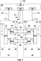
- FIG. 1 depicts a schematic block diagram.
- An apparatus 100 comprises receiving means 102 or determining means for obtaining an input data stream A.
- Propagating means 104 are provided for propagating the input data stream A through a plurality of consecutive input processing stages S10, S11.
- the input data stream A is provided at an input section IN_10 of the consecutive input processing stages S10, S11.
- a plurality of output data streams C1, C2, C3, and C4 is provided at an output section OUT_10 of the plurality of consecutive input processing stages S10, S11.
- the plurality of input processing stages S10, S11 comprise an increasing number of processing units S10a; S11a, S11b per processing stage S10, S11 in the direction of the output section OUT_10.
- the respective processing unit S10a, S11a, S11b determines a plurality of output streams B1, B2; C1, C2; C3, C4 based on its input data stream A; B1; B2 and based on a scheduling scheme LB, PD, PS that is associated with the respective input processing stage S10, S11.
- the scheduling schemes LB, PD, PS differ from each other at least between adjacent input processing stages S10, S11.
- Transmitting means 106 of the apparatus 100 transmit the plurality of output data streams C1, C2, C3, and C4 provided at the output section OUT_10 via a plurality of communication channels Ch1, Ch2, Ch3, and Ch4
- the plurality of communication channels Ch1, Ch2, Ch3, Ch4 differ in at least one of space, time, frequency and code.
- the communication channels Ch1-4 are separate radio channels and differ in space and/or frequency.
- the communication channels Ch1-4 are communication paths along a network between the apparatuses 100 and 200.
- a data stream like the input data stream A or the output data stream S1 comprises a plurality of data packets.
- a data packet comprises at least payload data and may comprise control data.
- An input processing stage like the input processing stage S10 comprises at least one processing unit.
- the processing units of the respective input processing stage operate according to a configuration of the plurality of input processing stages, wherein each input processing stage is associated with a single scheduling scheme.
- the consecutive input processing stages comprise an input data stream and a plurality of output data streams, wherein each one of the input processing stages comprises at least one input data stream and a plurality of output data streams.
- the processing stages S10 and S11 have the input data stream A, they are termed input processing stages.
- the plurality of communication channels Ch1, Ch2, Ch3, Ch4 are radio links between nodes of a radio communications network.
- the radio link refers to a connection between two of the plurality of nodes of the radio communications network.
- the radio link is the physical and/or logical network component used to interconnect nodes in the radio communications network.
- a link protocol is a suite of methods that operate between adjacent nodes of a network segment of the radio communications network. Each output stream at the output section OUT_10 is assigned to a separate radio link.
- the plurality of communication channels Ch1, Ch2, Ch3, Ch4 are data paths along a plurality of network entities of a communication network.
- the data paths can comprise a different number of nodes, even of different network segments of different communications networks, and a different number of links between the transmitting and the receiving apparatus.
- multipath routing can be used to determine the plurality of data paths. Then, by means of the apparatus 100, each output stream at the output section OUT_10 is assigned to a separate data path.
- Multipath routing is a routing technique simultaneously using multiple alternative paths through a network.
- the apparatus 200 comprises receiving means 202 for receiving a plurality of input data streams C1, C2, C3, C4 via a plurality of communication channels Ch1, Ch2, Ch3, and Ch4.
- the apparatus 200 comprises propagating means 204 for propagating the plurality of input data streams C1, C2, C3, C4 through a plurality of consecutive output processing stages S20, S21, wherein the plurality of received input data streams C1, C2, C3, C4 is provided at an input section IN_20 of the consecutive output processing stages S20, S21, wherein an output data stream E is provided at an output section OUT_20 of the plurality of consecutive output processing stages S20, S21, wherein the plurality of output processing stages S20, S21 comprise a decreasing number of processing units S20a, S20b, S21a per output processing stage S20, S21 in the direction of the output section OUT_20, wherein the respective processing unit S20a, S20b; S21a determines an output data stream D1; D2; E based on its plurality of input data streams C
- a data stream like the input data stream C1 or the output data stream E comprises a plurality of data packets.
- a data packet comprises at least payload data and may comprise control data.
- An output processing stage like the output processing stage S20 comprises at least one processing unit.
- the processing units of the respective output processing stage operate according to a configuration of the plurality of output processing stages, wherein each output processing stage is associated with a single scheduling scheme.
- the consecutive output processing stages comprise a plurality of input data streams and at least one output data stream, wherein the number of output data streams reduces towards the output section OUT_20.
- the processing stages S20 and S21 determine the output data stream E, they are termed output processing stages.
- a new 'virtual' communication channel is created that can be used in a further step as an input to a second stage where an additional scheduling scheme is applied.
- This method can be referred to as cascaded multi-connectivity.
- the method can be applied to different combinations to optimize the system with respect to a defined KPI based on the properties of each individual link or communication channel.
- the proposed communication scheme combines the advantages of multiple different scheduling techniques by cascading them and can thus improve latency and reliability performance of wireless communication systems in particular.
- An apparatus 300 is provided for configuring the apparatuses 100 and 200.
- the apparatus 300 comprises receiving means 302 or determining means or provisioning means for obtaining at least one data traffic requirement DTR associated with an input data stream A and an output data stream B.
- the apparatus 300 further comprises receiving means 304 or determining means for obtaining present states ps1, ps2, ps3, ps4 of a plurality of communication channels Ch1, Ch2, Ch3, and Ch4.
- the apparatus comprises determining means 306, 308 for determining at least one configuration c_in, c_out for a plurality of processing stages S10, S11; S20, S21 based on the at least one data traffic requirement DTR and based on the plurality of presents states s1, s2, s3, s4 of the plurality of communication channels Ch1, Ch2, Ch3, Ch4, wherein the at least one configuration c_in; c_out comprises a plurality of associations between one of the processing stages S10, S11, S20, S21 and one of a plurality of scheduling schemes LB, PD, PS.
- Provisioning means or transmitting means 316, 318 of the apparatus 300 are configured for providing or transmitting the at least one configuration c_in, c_out to the apparatus 100 or 200.
- the configuration c_in for a plurality of consecutive input processing stages S10, S11 comprises a first order of scheduling schemes LB, PD, PS, wherein the configuration c_out of a plurality of consecutive output processing stages S20, S21 comprises a second order of scheduling schemes LB, PD, PS, and wherein the first and second order are inverse to each other. Therefore, a cascade of compatible input processing stages S10, S11 und output processing stages S20, S21 are provided.
- the configuration c_in and/or c_out comprises the order of processing stages and the number of links and their association with the respective scheduling scheme LB, PD or PS.
- the apparatus 300 is separated from the apparatuses 100 and 200. According to another example, the apparatus 300 is part of the apparatus 100 and/or 200.
- Load Balancing can reduce the queuing and access latency by increasing the inter-packet-gap (IPG) and thus reducing the load per path.
- the packet splitting, PS scheme reduces the payload size per path and can thus reduce the transmission latency.
- Packet Duplication, PD increases the diversity by sending a copy of the packet over multiple communication channels.
- the apparatus 300 receives traffic requirements and link information as input and selects the channels for operation and which cascaded scheduling scheme is used. It shares this information with the apparatuses 100 and 200.
- An example architecture is to place the apparatus 300 onto the transmitting apparatus 100 and inform the receiving apparatus 200 of the selected configuration by using a designated field in the packet header.
- the apparatus 300 After initial reception of the requirements of the traffic flow to be scheduled and the information about the present status of the communication channels (e.g. delay statistics, loss rates), the apparatus 300 determines an optimal configuration based on the provided traffic requirement. The configuration is signaled to the apparatuses 100 and 200 afterwards.
- a scheduled update of the determination of the configuration is conducted if the link conditions or traffic requirements change to avoid a permanently changing configuration and enable a change of the configuration based on a timing period.
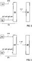
- Figure 2 depicts a schematic block diagram for configuring the transmitting apparatus 100 of figure 1 .
- the apparatus 100 comprises receiving means or determining means 110 for obtaining a configuration c_in for the input processing stages, wherein the configuration c_in comprises at least a plurality of associations between one of the input processing stages and one of the plurality of scheduling schemes.
- Applying means 120 apply the configuration c_in to the plurality of consecutive input processing stages.
- the determining means 110 comprises receiving means or determining means or providing means 112 to provide at least one data traffic requirement DTR associated with the input data stream of the consecutive input processing stages.
- Receiving means 114 or determining means are provided to obtain a respective present state ps1, ps2, ps3, ps4 of the plurality of communication channels.
- Determining or processing means 116 are provided to obtain the configuration c_in for the plurality of consecutive input processing stages based on the at least one data traffic requirement DTR and based on the plurality of present states ps1, ps2, ps3, ps4 of the plurality of communication channels, wherein the configuration c_in comprises at least a plurality of associations between one of the input processing stages and one of a plurality of scheduling schemes.
- the configuration c_in is determined and applied if the at least one data traffic requirement DTR changes and/or if one of the present stages ps1 to ps4 changes.
- Figure 3 depicts a schematic block diagram for configuring the receiving apparatus 200 of figure 1 .
- Receiving or determining means 210 obtain a configuration c_out for the output processing stages, wherein the configuration c_out comprises at least a plurality of associations between one of the output processing stages and one of the plurality of scheduling schemes.
- Applying means 220 apply the configuration c_out to the plurality of consecutive output processing stages.
- the determining means 210 comprise: Receiving means or determining means or providing means 212 for providing at least one data traffic requirement DTR associated with the output data stream; Receiving means 214 or determining means to obtain a respective present state ps1, ps2, ps3, ps4 of the plurality of communication channels; and determining means 216 for determining the configuration c_out for the plurality of consecutive output processing stages based on the at least one data traffic requirement DTR and based on the plurality of present states ps1, ps2, ps3, ps4 of the plurality of communication channels, wherein the configuration c_out comprises at least a plurality of associations between one of the output processing stages and one of a plurality of scheduling schemes.
- the configuration c_out is determined and applied if the at least one data traffic requirement DTR changes and/or if one of the present stages ps1 to ps4 changes.
- FIG 4 schematically depicts a distribution scheme LB, which can be also termed load balancing scheme.
- the packets of the input data stream are numbered according to its arrival time.
- the distribution scheme LB distributes the packets between the communication channels Ch1 and Ch2.
- the input packet of the respective input data stream is assigned, by means of the respective processing unit, to one of the plurality of output data streams.
- an output packet of the respective output data stream is assigned to one of the input packets of the plurality of input data streams, wherein the output packet of an output data stream of a respective processing unit is represented by an input packet of one of input data streams.
- Figure 5 schematically depicts a duplication scheme PD. The packets of the input data stream are numbered according to its arrival time. The duplication scheme PD duplicates the packets on the communication channels Ch1 and Ch2.
- an input packet of the respective input data stream is replicated, by means of the respective processing unit, in form of a respective output packet in the plurality of output data streams.
- the input packets of a plurality of input data streams are expected to be duplicated at the side of the transmitting apparatus 100 in order to de-duplicate the input packets.
- An output packet of an output data stream of a respective processing unit is determined based on expected duplicate input packets of different input data streams of the respective processing unit.
- Figure 6 schematically depicts a split scheme PS.
- the packets of the input data stream are numbered according to its arrival time.
- the split scheme PS splits each packet of the input data stream into a plurality of parts, for example packets 1.1 and 1.2, and transmits each part on a different one of the communication channels Ch1 and Ch2.
- the input packet of the respective input data stream is split up, by means of the respective processing unit, into the plurality of output packets of the output data streams.
- the input packets of different input data streams are reassembled on the receiver side and form an output packet of the respective output data stream.
- the parts of an output packet of a respective processing unit is determined based on a plurality of input packets of the respective processing unit, wherein each input packet represents or comprises a part of the output packet.
- Figure 7 schematically depicts an example with eight communication channels Ch1 to Ch8 available for use.
- the receiving apparatus 200 determines the output data stream E based on the input data streams arriving via the different communication channels Ch1 to Ch8.
- the input data streams pass through a first processing stages operating according to the scheduling scheme PS.
- the output data streams of the first processing stages are the input data streams of a second processing stage.
- the second processing stage operates according to the scheduling scheme LB.
- the output data streams of the second processing stage are the input data streams of the third processing stage that is operating according to the scheduling scheme PD.
- the third processing stage determines the output data stream E.
- This example for a cascaded multi-connectivity scheme provides packet splitting (PS) over two links or communication channels.
- Load Balancing (LB) is provided over two 'virtual' communication channels provided by two packet splitting processing entities of the first output processing stage.
- Packed Duplication (PD) is provided over two 'virtual' communication channels provided by two load balancing processing entities of the second output processing stage.
- the payload size is halved, the inter-packet gap, IPG, is doubled and additionally a diversity degree of two can be reached. This potentially decreases latency and improves reliability.
- a lower number of communication channels is selected to increase the efficiency of the communication system, such that the resources could e.g. be used by other applications or other users.
- Figure 8 depicts schematically a Wi-Fi example.
- the apparatus 300 is located in the upper MAC.
- the apparatus 300 selects the cascaded MC scheme in the form of the configurations c_in, c_out and configures the traffic steering.
- the apparatus 300 receives traffic requirements from the application and link information from PHY and lower MAC in form of present states ps1, ps2.
- the apparatus 300 uses these input parameters to configure the cascaded MC scheme via the configurations c_in and c_out.
- Figure 9 depicts schematically a 3GPP architecture.
- the multi-connectivity (MC) entity is split into a control part and an aggregation part.
- the MC control entity in form of the apparatus 300 uses information from collected radio characteristics and potentially also from a pQoS entity to decide which MC scheme or configuration c_in, c_out is used at a given point in time.
- the MC control entity in form of the apparatus 300 informs all related units about the used scheme in form of the determined configuration.
- the apparatus 300 could e.g. be located in the 5G Session Management Function, SMF.
- the user equipment UE comprises the transmitting apparatus 100, and the radio access node, RAN, comprises the receiving apparatus 200.
- the user equipment UE comprises the receiving apparatus 200 and the radio access node, RAN, comprise the transmitting apparatus 100.
- Measurement units 902 and 904 provide the present status of the communication channels to the apparatus 300.
- An MC aggregation entity could include both the functions of the apparatuses 100 and 200.
- the MC aggregation entity splits and aggregates the different links according to the selected MC scheme.
- the MC aggregation entity could e.g. be located in the RAN at PDCP Layer and use Dual-Connectivity.
- the MC aggregation entity could also be located at the MAC Layer and use Carrier Aggregation.
- the MC aggregation entity could also use multiple RANs (not shown) and reside in the User Plane Function, UPF.
Landscapes
- Engineering & Computer Science (AREA)
- Computer Networks & Wireless Communication (AREA)
- Signal Processing (AREA)
- Quality & Reliability (AREA)
- Data Exchanges In Wide-Area Networks (AREA)
- Mobile Radio Communication Systems (AREA)
Abstract
Description
- There are provided advantages in the area of digital communication.
- For example, wireless communication systems require lower latency and higher reliability in order to support emerging applications like industrial control, mobile robotics and V2X-services. A measure to enhance the latency and reliability performance of wireless communication systems is Multi- Connectivity (MC) where multiple communication paths are used at the same time. Examples for already existing MC systems are MP-TCP on Transport Layer or Dual Connectivity in 3GPP that can be utilized to enhance the throughput or improve the latency and reliability of the system. The existing MC schemes all offer the option to use a single scheduling scheme over two or multiple paths. For MP-TCP, Packet Duplication (PD) and Load Balancing (LB) are available scheduling options.
- The problems of the prior art are solved by methods according to
claim 1 and separate independent claims and by apparatuses according to further independent claims. - According to a first aspect a method is provided that comprises: receiving or determining an input data stream; propagating the input data stream through a plurality of consecutive input processing stages, wherein the input data stream is provided at an input section of the consecutive input processing stages, wherein a plurality of output data streams is provided at an output section of the plurality of consecutive input processing stages, wherein the plurality of input processing stages comprise an increasing number of processing units per processing stage in the direction of the output section, wherein the respective processing unit determines a plurality of output streams based on its input data stream and based on a scheduling scheme that is associated with the respective input processing stage, and wherein the scheduling schemes differ from each other at least between adjacent input processing stages; and transmitting the plurality of output data streams provided at the output section via a plurality of communication channels.
- Advantageously, the performance of data communication is increased with respect to efficiency, latency and reliability of the provided multi-connectivity scheduling schemes in the presence of multiple links or communication channels.
- According to an advantageous example, the method further comprises: receiving or determining a configuration for the input processing stages, wherein the configuration comprises at least a plurality of associations between one of the input processing stages and one of the plurality of scheduling schemes; and applying the configuration to the plurality of consecutive input processing stages.
- Advantageously, the configuration of the processing stages can be adapted by changing the scheduling schemes of the processing stages.
- According to an advantageous example, the determining of the configuration comprises: receiving or determining or providing at least one data traffic requirement associated with the input data stream of the consecutive input processing stages; receiving or determining a respective present state of the plurality of communication channels; determining the configuration for the plurality of consecutive input processing stages based on the at least one data traffic requirement and based on the plurality of present states of the plurality of communication channels, wherein the configuration comprises at least a plurality of associations between one of the input processing stages and one of a plurality of scheduling schemes.
- Advantageously, the configuration is adapted to the state of the available communication channels. Therefore, the scheduling schemes are adapted to the channel conditions.
- According to an advantageous example, the plurality of scheduling schemes comprise: a duplication scheme, wherein an input packet of the respective input data stream is replicated, by means of the respective processing unit, in form of a respective output packet in the plurality of output data streams; a split scheme, wherein the input packet of the respective input data stream is split up, by means of the respective processing unit, into the plurality of output packets of the output data streams; and a distribution scheme, wherein the input packet of the respective input data stream is assigned, by means of the respective processing unit, to one of the plurality of output data streams.
- The scheduling schemes provide their advantages together applied one after another according to the processing stages.
- According to a second aspect, an apparatus comprises: receiving means or determining means for obtaining an input data stream; propagating means for propagating the input data stream through a plurality of consecutive input processing stages, wherein the input data stream is provided at an input section of the consecutive input processing stages, wherein a plurality of output data streams is provided at an output section of the plurality of consecutive input processing stages, wherein the plurality of input processing stages comprise an increasing number of processing units per processing stage in the direction of the output section, wherein the respective processing unit determines a plurality of output streams based on its input data stream and based on a scheduling scheme that is associated with the respective input processing stage, and wherein the scheduling schemes differ from each other at least between adjacent input processing stages; and transmitting means for transmitting the plurality of output data streams provided at the output section via a plurality of communication channels.
- According to a third aspect of the description, a method is provided that comprises: receiving a plurality of input data streams via a plurality of communication channels; propagating the plurality of input data streams through a plurality of consecutive output processing stages, wherein the plurality of received input data streams is provided at an input section of the consecutive output processing stages, wherein an output data stream is provided at an output section of the plurality of consecutive output processing stages, wherein the plurality of output processing stages comprise a decreasing number of processing units per output processing stage in the direction of the output section, wherein the respective processing unit determines an output data stream based on its plurality of input data streams and based on a scheduling scheme that is associated with the respective output processing stage, and wherein the scheduling schemes differ from each other at least between adjacent output processing stages; and providing the output data stream at the output section.
- Advantageously, the performance of data communication is increased with respect to efficiency, latency and reliability of the provided multi-connectivity scheduling schemes in the presence of multiple links or communication channels.
- According to an advantageous example, the method further comprises: receiving or determining a configuration for the output processing stages, wherein the configuration comprises at least a plurality of associations between one of the output processing stages and one of the plurality of scheduling schemes; and applying the configuration to the plurality of consecutive output processing stages.
- Advantageously, the configuration of the processing stages can be adapted by changing the scheduling schemes of the processing stages.
- According to an advantageous example, the determining of the configuration comprises: receiving or determining or providing at least one data traffic requirement associated with the output data stream; receiving or determining a respective present state of the plurality of communication channels; determining the configuration for the plurality of consecutive output processing stages based on the at least one data traffic requirement and based on the plurality of present states of the plurality of communication channels, wherein the configuration comprises at least a plurality of associations between one of the output processing stages and one of a plurality of scheduling schemes.
- Advantageously, the configuration is adapted to the state of the available communication channels. Therefore, the scheduling schemes are adapted to the channel conditions.
- According to an advantageous example, the plurality of scheduling schemes comprise: a duplication scheme wherein an output packet of an output data stream is determined based on expected duplicate input packets of different input data streams; a split scheme wherein parts of an output packet is determined based on a plurality of input packets, wherein each input packet represents a part of the output packet; a distribution scheme, wherein the output packet of an output data stream is represented by an input packet of one of input data streams.
- The scheduling schemes provide their advantages together applied one after another according to the processing stages.
- According to a fourth aspect of the description an apparatus is provided that comprises: receiving means for receiving a plurality of input data streams via a plurality of communication channels; propagating means for propagating the plurality of input data streams through a plurality of consecutive output processing stages, wherein the plurality of received input data streams is provided at an input section of the consecutive output processing stages, wherein an output data stream is provided at an output section of the plurality of consecutive output processing stages, wherein the plurality of output processing stages comprise a decreasing number of processing units per output processing stage in the direction of the output section, wherein the respective processing unit determines an output data stream based on its plurality of input data streams and based on a scheduling scheme that is associated with the respective output processing stage, and wherein the scheduling schemes differ from each other at least between adjacent output processing stages; and provisioning means for providing the output data stream at the output section.
- According to a sixth aspect of the description, a method is provided that comprises: receiving or determining or providing at least one data traffic requirement associated with an input data stream and an output data stream; receiving or determining a respective present state of a plurality of communication channels; determining at least one configuration for a plurality of processing stages based on the at least one data traffic requirement and based on the plurality of presents states of the plurality of communication channels, wherein the at least one configuration comprises a plurality of associations between one of the processing stages and one of a plurality of scheduling schemes; and providing or transmitting the at least one configuration.
- According to an advantageous example, the configuration for a plurality of consecutive input processing stages comprises a first order of scheduling schemes, wherein the configuration of a plurality of consecutive output processing stages comprises a second order of scheduling schemes, and wherein the first and second order are inverse to each other.
- Advantageously, the configurations provide a cascaded transmission scheme based on multiple connections / communication channels.
- According to a seventh aspect of the description an apparatus is provided that comprises: receiving means or determining means or provisioning means for obtaining at least one data traffic requirement associated with an input data stream and an output data stream; receiving means or determining means for obtaining present states of a plurality of communication channels; determining means for determining at least one configuration for a plurality of processing stages based on the at least one data traffic requirement and based on the plurality of presents states of the plurality of communication channels, wherein the at least one configuration comprises a plurality of associations between one of the processing stages and one of a plurality of scheduling schemes; and provisioning means or transmitting means for providing or transmitting the at least one configuration.
- Figure 1
- depicts a schematic block diagram for digital communication;
- Figures 2 and 3
- each depicts a schematic block diagram for determining and applying a communication;
- Figures 4 to 6
- each depict a respective scheduling scheme;
- Figure 7
- depicts schematically a combined scheduling scheme;
- Figure 8
- depicts a first exemplary embodiment of the communication scheme; and
- Figure 9
- depicts a second exemplary embodiment of the communication scheme.
-
Figure 1 depicts a schematic block diagram. Anapparatus 100 comprisesreceiving means 102 or determining means for obtaining an input data stream A. Propagating means 104 are provided for propagating the input data stream A through a plurality of consecutive input processing stages S10, S11. The input data stream A is provided at an input section IN_10 of the consecutive input processing stages S10, S11. A plurality of output data streams C1, C2, C3, and C4 is provided at an output section OUT_10 of the plurality of consecutive input processing stages S10, S11. The plurality of input processing stages S10, S11 comprise an increasing number of processing units S10a; S11a, S11b per processing stage S10, S11 in the direction of the output section OUT_10. The respective processing unit S10a, S11a, S11b determines a plurality of output streams B1, B2; C1, C2; C3, C4 based on its input data stream A; B1; B2 and based on a scheduling scheme LB, PD, PS that is associated with the respective input processing stage S10, S11. The scheduling schemes LB, PD, PS differ from each other at least between adjacent input processing stages S10, S11. Transmitting means 106 of theapparatus 100 transmit the plurality of output data streams C1, C2, C3, and C4 provided at the output section OUT_10 via a plurality of communication channels Ch1, Ch2, Ch3, and Ch4 - The plurality of communication channels Ch1, Ch2, Ch3, Ch4 differ in at least one of space, time, frequency and code. For example, the communication channels Ch1-4 are separate radio channels and differ in space and/or frequency. In another example, the communication channels Ch1-4 are communication paths along a network between the
apparatuses - For the
apparatus 100, the following applies: A data stream like the input data stream A or the output data stream S1 comprises a plurality of data packets. A data packet comprises at least payload data and may comprise control data. An input processing stage like the input processing stage S10 comprises at least one processing unit. The processing units of the respective input processing stage operate according to a configuration of the plurality of input processing stages, wherein each input processing stage is associated with a single scheduling scheme. The consecutive input processing stages comprise an input data stream and a plurality of output data streams, wherein each one of the input processing stages comprises at least one input data stream and a plurality of output data streams. As the processing stages S10 and S11 have the input data stream A, they are termed input processing stages. - According to an advantageous example, the plurality of communication channels Ch1, Ch2, Ch3, Ch4 are radio links between nodes of a radio communications network. The radio link refers to a connection between two of the plurality of nodes of the radio communications network. The radio link is the physical and/or logical network component used to interconnect nodes in the radio communications network. A link protocol is a suite of methods that operate between adjacent nodes of a network segment of the radio communications network. Each output stream at the output section OUT_10 is assigned to a separate radio link.
- According to an advantageous example, the plurality of communication channels Ch1, Ch2, Ch3, Ch4 are data paths along a plurality of network entities of a communication network. The data paths can comprise a different number of nodes, even of different network segments of different communications networks, and a different number of links between the transmitting and the receiving apparatus. For example, multipath routing can be used to determine the plurality of data paths. Then, by means of the
apparatus 100, each output stream at the output section OUT_10 is assigned to a separate data path. - Multipath routing is a routing technique simultaneously using multiple alternative paths through a network.
- The
apparatus 200 comprises receiving means 202 for receiving a plurality of input data streams C1, C2, C3, C4 via a plurality of communication channels Ch1, Ch2, Ch3, and Ch4. Theapparatus 200 comprises propagating means 204 for propagating the plurality of input data streams C1, C2, C3, C4 through a plurality of consecutive output processing stages S20, S21, wherein the plurality of received input data streams C1, C2, C3, C4 is provided at an input section IN_20 of the consecutive output processing stages S20, S21, wherein an output data stream E is provided at an output section OUT_20 of the plurality of consecutive output processing stages S20, S21, wherein the plurality of output processing stages S20, S21 comprise a decreasing number of processing units S20a, S20b, S21a per output processing stage S20, S21 in the direction of the output section OUT_20, wherein the respective processing unit S20a, S20b; S21a determines an output data stream D1; D2; E based on its plurality of input data streams C1, C2, C3, C4; D1, D2 and based on a scheduling scheme LB; PD, PS that is associated with the respective output processing stage S20, S21, and wherein the scheduling schemes LB; PD, PS differ from each other at least between adjacent output processing stages S20, S21. Theapparatus 200 comprises provisioning means 206 for providing the output data stream E at the output section OUT_20. - For the
apparatus 200, the following applies: A data stream like the input data stream C1 or the output data stream E comprises a plurality of data packets. A data packet comprises at least payload data and may comprise control data. An output processing stage like the output processing stage S20 comprises at least one processing unit. The processing units of the respective output processing stage operate according to a configuration of the plurality of output processing stages, wherein each output processing stage is associated with a single scheduling scheme. The consecutive output processing stages comprise a plurality of input data streams and at least one output data stream, wherein the number of output data streams reduces towards the output section OUT_20. As the processing stages S20 and S21 determine the output data stream E, they are termed output processing stages. - By applying one of the proposed scheduling schemes on a subset of the available communication channels a new 'virtual' communication channel is created that can be used in a further step as an input to a second stage where an additional scheduling scheme is applied. This method can be referred to as cascaded multi-connectivity. The method can be applied to different combinations to optimize the system with respect to a defined KPI based on the properties of each individual link or communication channel. The proposed communication scheme combines the advantages of multiple different scheduling techniques by cascading them and can thus improve latency and reliability performance of wireless communication systems in particular.
- An
apparatus 300 is provided for configuring theapparatuses apparatus 300 comprises receiving means 302 or determining means or provisioning means for obtaining at least one data traffic requirement DTR associated with an input data stream A and an output data stream B. Theapparatus 300 further comprises receiving means 304 or determining means for obtaining present states ps1, ps2, ps3, ps4 of a plurality of communication channels Ch1, Ch2, Ch3, and Ch4. The apparatus comprises determining means 306, 308 for determining at least one configuration c_in, c_out for a plurality of processing stages S10, S11; S20, S21 based on the at least one data traffic requirement DTR and based on the plurality of presents states s1, s2, s3, s4 of the plurality of communication channels Ch1, Ch2, Ch3, Ch4, wherein the at least one configuration c_in; c_out comprises a plurality of associations between one of the processing stages S10, S11, S20, S21 and one of a plurality of scheduling schemes LB, PD, PS. Provisioning means or transmitting means 316, 318 of theapparatus 300 are configured for providing or transmitting the at least one configuration c_in, c_out to theapparatus - The configuration c_in for a plurality of consecutive input processing stages S10, S11 comprises a first order of scheduling schemes LB, PD, PS, wherein the configuration c_out of a plurality of consecutive output processing stages S20, S21 comprises a second order of scheduling schemes LB, PD, PS, and wherein the first and second order are inverse to each other. Therefore, a cascade of compatible input processing stages S10, S11 und output processing stages S20, S21 are provided.
- According to an example, the configuration c_in and/or c_out comprises the order of processing stages and the number of links and their association with the respective scheduling scheme LB, PD or PS.
- According to the shown example, the
apparatus 300 is separated from theapparatuses apparatus 300 is part of theapparatus 100 and/or 200. - By cascading different scheduling schemes, their advantages can be combined when multiple communication channels are available. Load Balancing, LB, can reduce the queuing and access latency by increasing the inter-packet-gap (IPG) and thus reducing the load per path. The packet splitting, PS, scheme reduces the payload size per path and can thus reduce the transmission latency. Packet Duplication, PD, increases the diversity by sending a copy of the packet over multiple communication channels.
- The
apparatus 300 receives traffic requirements and link information as input and selects the channels for operation and which cascaded scheduling scheme is used. It shares this information with theapparatuses apparatus 300 onto the transmittingapparatus 100 and inform the receivingapparatus 200 of the selected configuration by using a designated field in the packet header. - After initial reception of the requirements of the traffic flow to be scheduled and the information about the present status of the communication channels (e.g. delay statistics, loss rates), the
apparatus 300 determines an optimal configuration based on the provided traffic requirement. The configuration is signaled to theapparatuses - If a change in the link conditions / present states or the traffic requirement is observed, a recalculation of the scheduling decision is triggered.
- According to an example, a scheduled update of the determination of the configuration is conducted if the link conditions or traffic requirements change to avoid a permanently changing configuration and enable a change of the configuration based on a timing period.
-
Figure 2 depicts a schematic block diagram for configuring the transmittingapparatus 100 offigure 1 . Theapparatus 100 comprises receiving means or determiningmeans 110 for obtaining a configuration c_in for the input processing stages, wherein the configuration c_in comprises at least a plurality of associations between one of the input processing stages and one of the plurality of scheduling schemes. Applying means 120 apply the configuration c_in to the plurality of consecutive input processing stages. - The determining means 110 comprises receiving means or determining means or providing
means 112 to provide at least one data traffic requirement DTR associated with the input data stream of the consecutive input processing stages. Receiving means 114 or determining means are provided to obtain a respective present state ps1, ps2, ps3, ps4 of the plurality of communication channels. - Determining or processing means 116 are provided to obtain the configuration c_in for the plurality of consecutive input processing stages based on the at least one data traffic requirement DTR and based on the plurality of present states ps1, ps2, ps3, ps4 of the plurality of communication channels, wherein the configuration c_in comprises at least a plurality of associations between one of the input processing stages and one of a plurality of scheduling schemes.
- The configuration c_in is determined and applied if the at least one data traffic requirement DTR changes and/or if one of the present stages ps1 to ps4 changes.
-
Figure 3 depicts a schematic block diagram for configuring the receivingapparatus 200 offigure 1 . Receiving or determiningmeans 210 obtain a configuration c_out for the output processing stages, wherein the configuration c_out comprises at least a plurality of associations between one of the output processing stages and one of the plurality of scheduling schemes. Applying means 220 apply the configuration c_out to the plurality of consecutive output processing stages. - The determining means 210 comprise: Receiving means or determining means or providing
means 212 for providing at least one data traffic requirement DTR associated with the output data stream; Receiving means 214 or determining means to obtain a respective present state ps1, ps2, ps3, ps4 of the plurality of communication channels; and determiningmeans 216 for determining the configuration c_out for the plurality of consecutive output processing stages based on the at least one data traffic requirement DTR and based on the plurality of present states ps1, ps2, ps3, ps4 of the plurality of communication channels, wherein the configuration c_out comprises at least a plurality of associations between one of the output processing stages and one of a plurality of scheduling schemes. - The configuration c_out is determined and applied if the at least one data traffic requirement DTR changes and/or if one of the present stages ps1 to ps4 changes.
-
Figure 4 schematically depicts a distribution scheme LB, which can be also termed load balancing scheme. The packets of the input data stream are numbered according to its arrival time. The distribution scheme LB distributes the packets between the communication channels Ch1 and Ch2. - At the transmitting
apparatus 100 offigure 1 , the input packet of the respective input data stream is assigned, by means of the respective processing unit, to one of the plurality of output data streams. - At the receiving
apparatus 200 offigure 1 , an output packet of the respective output data stream is assigned to one of the input packets of the plurality of input data streams, wherein the output packet of an output data stream of a respective processing unit is represented by an input packet of one of input data streams.Figure 5 schematically depicts a duplication scheme PD. The packets of the input data stream are numbered according to its arrival time. The duplication scheme PD duplicates the packets on the communication channels Ch1 and Ch2. - At the transmitting
apparatus 100 offigure 1 , an input packet of the respective input data stream is replicated, by means of the respective processing unit, in form of a respective output packet in the plurality of output data streams. - At the receiving
apparatus 200 offigure 1 , the input packets of a plurality of input data streams are expected to be duplicated at the side of the transmittingapparatus 100 in order to de-duplicate the input packets. An output packet of an output data stream of a respective processing unit is determined based on expected duplicate input packets of different input data streams of the respective processing unit. -
Figure 6 schematically depicts a split scheme PS. The packets of the input data stream are numbered according to its arrival time. The split scheme PS splits each packet of the input data stream into a plurality of parts, for example packets 1.1 and 1.2, and transmits each part on a different one of the communication channels Ch1 and Ch2. - At the transmitting
apparatus 100 offigure 1 , the input packet of the respective input data stream is split up, by means of the respective processing unit, into the plurality of output packets of the output data streams. - At the receiving
apparatus 200 offigure 1 , the input packets of different input data streams are reassembled on the receiver side and form an output packet of the respective output data stream. The parts of an output packet of a respective processing unit is determined based on a plurality of input packets of the respective processing unit, wherein each input packet represents or comprises a part of the output packet. -
Figure 7 schematically depicts an example with eight communication channels Ch1 to Ch8 available for use. The receivingapparatus 200 determines the output data stream E based on the input data streams arriving via the different communication channels Ch1 to Ch8. The input data streams pass through a first processing stages operating according to the scheduling scheme PS. The output data streams of the first processing stages are the input data streams of a second processing stage. The second processing stage operates according to the scheduling scheme LB. The output data streams of the second processing stage are the input data streams of the third processing stage that is operating according to the scheduling scheme PD. The third processing stage determines the output data stream E. - This example for a cascaded multi-connectivity scheme provides packet splitting (PS) over two links or communication channels. Load Balancing (LB) is provided over two 'virtual' communication channels provided by two packet splitting processing entities of the first output processing stage. Packed Duplication (PD) is provided over two 'virtual' communication channels provided by two load balancing processing entities of the second output processing stage. In this example the payload size is halved, the inter-packet gap, IPG, is doubled and additionally a diversity degree of two can be reached. This potentially decreases latency and improves reliability.
- In an additional example, a lower number of communication channels is selected to increase the efficiency of the communication system, such that the resources could e.g. be used by other applications or other users.
-
Figure 8 depicts schematically a Wi-Fi example. Theapparatus 300 is located in the upper MAC. Theapparatus 300 selects the cascaded MC scheme in the form of the configurations c_in, c_out and configures the traffic steering. Theapparatus 300 receives traffic requirements from the application and link information from PHY and lower MAC in form of present states ps1, ps2. Theapparatus 300 uses these input parameters to configure the cascaded MC scheme via the configurations c_in and c_out. -
Figure 9 depicts schematically a 3GPP architecture. The multi-connectivity (MC) entity is split into a control part and an aggregation part. - The MC control entity in form of the
apparatus 300 uses information from collected radio characteristics and potentially also from a pQoS entity to decide which MC scheme or configuration c_in, c_out is used at a given point in time. - The MC control entity in form of the
apparatus 300 informs all related units about the used scheme in form of the determined configuration. Theapparatus 300 could e.g. be located in the 5G Session Management Function, SMF. - In a shown uplink scenario, the user equipment UE comprises the transmitting
apparatus 100, and the radio access node, RAN, comprises the receivingapparatus 200. In a downlink scenario, the user equipment UE comprises the receivingapparatus 200 and the radio access node, RAN, comprise the transmittingapparatus 100. -
Measurement units apparatus 300. - An MC aggregation entity could include both the functions of the
apparatuses
Claims (14)
- A method comprising
receiving (102) or determining an input data stream (A);
propagating (104) the input data stream (A) through a plurality of consecutive input processing stages (S10, S11), wherein the input data stream (A) is provided at an input section (IN_10) of the consecutive input processing stages (S10, S11), wherein a plurality of output data streams (C1, C2, C3, C4) is provided at an output section (OUT_10) of the plurality of consecutive input processing stages (S10, S11), wherein the plurality of input processing stages (S10, S11) comprise an increasing number of processing units (S10a; S11a, S11b) per processing stage (S10, S11) in the direction of the output section (OUT_10), wherein the respective processing unit (S10a; S11a, S11b) determines a plurality of output streams (B1, B2; C1, C2; C3, C4) based on its input data stream (A; B1; B2) and based on a scheduling scheme (LB; PD, PS) that is associated with the respective input processing stage (S10, S11), and wherein the scheduling schemes (LB; PD, PS) differ from each other at least between adjacent input processing stages (S10, S11); and
transmitting (106) the plurality of output data streams (C1, C2, C3, C4) provided at the output section (OUT_10) via a plurality of communication channels (Ch1, Ch2, Ch3, Ch4). - The method according to claim 1 comprising
receiving or determining (110) a configuration (c_in) for the input processing stages (S10, S11), wherein the configuration comprises at least a plurality of associations between one of the input processing stages (S10, S11) and one of the plurality of scheduling schemes (LB; PD, PS); and
applying (120) the configuration to the plurality of consecutive input processing stages (S10, S11). - The method according to claim 2, wherein the determining (110) of the configuration comprises:receiving or determining or providing (112) at least one data traffic requirement (DTR) associated with the input data stream (A) of the consecutive input processing stages (S10, S11);receiving (114) or determining a respective present state (ps1, ps2, ps3, ps4) of the plurality of communication channels (Ch1, Ch2, Ch3, Ch4);determining (116) the configuration (c_in) for the plurality of consecutive input processing stages (S10, S11) based on the at least one data traffic requirement (DTR) and based on the plurality of present states (ps1, ps2, ps3, ps4) of the plurality of communication channels (Ch1, Ch2, Ch3, Ch4), wherein the configuration (c_in) comprises at least a plurality of associations between one of the input processing stages (S10, S11) and one of a plurality of scheduling schemes (LB; PD, PS).
- The method according to one of the preceding claims, wherein the plurality of scheduling schemes comprise:a duplication scheme (PD), wherein an input packet of the respective input data stream is replicated, by means of the respective processing unit (S10a; S11a, S11b), in form of a respective output packet in the plurality of output data streams;a split scheme (PS), wherein the input packet of the respective input data stream is split up, by means of the respective processing unit (S10a; S11a, S11b), into the plurality of output packets of the output data streams;a distribution scheme (LB), wherein the input packet of the respective input data stream is assigned, by means of the respective processing unit (S10a; S11a, S11b), to one of the plurality of output data streams.
- An apparatus (100) comprising
receiving means (102) or determining means for obtaining an input data stream (A);
propagating means (104) for propagating the input data stream (A) through a plurality of consecutive input processing stages (S10, S11), wherein the input data stream (A) is provided at an input section (IN_10) of the consecutive input processing stages (S10, S11), wherein a plurality of output data streams (C1, C2, C3, C4) is provided at an output section (OUT_10) of the plurality of consecutive input processing stages (S10, S11), wherein the plurality of input processing stages (S10, S11) comprise an increasing number of processing units (S10a; S11a, S11b) per processing stage (S10, S11) in the direction of the output section (OUT_10), wherein the respective processing unit (S10a; S11a, S11b) determines a plurality of output streams (B1, B2; C1, C2; C3, C4) based on its input data stream (A; B1; B2) and based on a scheduling scheme (LB; PD, PS) that is associated with the respective input processing stage (S10, S11), and wherein the scheduling schemes (LB; PD, PS) differ from each other at least between adjacent input processing stages (S10, S11); and
transmitting means (106) for transmitting the plurality of output data streams (C1, C2, C3, C4) provided at the output section (OUT_10) via a plurality of communication channels (Ch1, Ch2, Ch3, Ch4). - A method comprising
receiving (202) a plurality of input data streams (C1, C2, C3, C4) via a plurality of communication channels (Ch1, Ch2, Ch3, Ch4);
propagating (204) the plurality of input data streams (C1, C2, C3, C4) through a plurality of consecutive output processing stages (S20, S21), wherein the plurality of received input data streams (C1, C2, C3, C4) is provided at an input section (IN_20) of the consecutive output processing stages (S20, S21), wherein an output data stream (E) is provided at an output section (OUT_20) of the plurality of consecutive output processing stages (S20, S21), wherein the plurality of output processing stages (S20, S21) comprise a decreasing number of processing units (S20a, S20b, S21a) per output processing stage (S20, S21) in the direction of the output section (OUT_20), wherein the respective processing unit (S20a, S20b; S21a) determines an output data stream (D1; D2; E) based on its plurality of input data streams (C1, C2, C3, C4; D1, D2) and based on a scheduling scheme (LB; PD, PS) that is associated with the respective output processing stage (S20, S21), and wherein the scheduling schemes (LB; PD, PS) differ from each other at least between adjacent output processing stages (S20, S21); and
providing (206) the output data stream (E) at the output section (OUT_20). - The method according to claim 6 comprising
receiving or determining (210) a configuration (c_out) for the output processing stages (S20, S21), wherein the configuration (c_out) comprises at least a plurality of associations between one of the output processing stages (S20, S21) and one of the plurality of scheduling schemes (LB; PD; PS); and
applying (220) the configuration (c_out) to the plurality of consecutive output processing stages (S20, S21). - The method according to claim 7, wherein the determining (210) of the configuration (210) comprises:receiving or determining or providing (212) at least one data traffic requirement (DTR) associated with the output data stream (E);receiving (214) or determining a respective present state (ps1, ps2, ps3, ps4) of the plurality of communication channels (Ch1, Ch2, Ch3, Ch4);determining (216) the configuration (c_out) for the plurality of consecutive output processing stages (S20, S21) based on the at least one data traffic requirement (DTR) and based on the plurality of present states (ps1, ps2, ps3, ps4) of the plurality of communication channels (Ch1, Ch2, Ch3, Ch4), wherein the configuration (c_out) comprises at least a plurality of associations between one of the output processing stages (S20, S21) and one of a plurality of scheduling schemes (LB; PD, PS).
- The method according to one of the claims 6 to 8, wherein the plurality of scheduling schemes comprise:a duplication scheme (PD) wherein an output packet of an output data stream is determined based on expected duplicate input packets of different input data streams;a split scheme (PS) wherein parts of an output packet is determined based on a plurality of input packets, wherein each input packet represents a part of the output packet;a distribution scheme (LB), wherein the output packet of an output data stream is represented by an input packet of one of input data streams.
- An apparatus (200) comprising
receiving means (202) for receiving a plurality of input data streams (C1, C2, C3, C4) via a plurality of communication channels (Ch1, Ch2, Ch3, Ch4);
propagating means (204) for propagating the plurality of input data streams (C1, C2, C3, C4) through a plurality of consecutive output processing stages (S20, S21), wherein the plurality of received input data streams (C1, C2, C3, C4) is provided at an input section (IN_20) of the consecutive output processing stages (S20, S21), wherein an output data stream (E) is provided at an output section (OUT_20) of the plurality of consecutive output processing stages (S20, S21), wherein the plurality of output processing stages (S20, S21) comprise a decreasing number of processing units (S20a, S20b, S21a) per output processing stage (S20, S21) in the direction of the output section (OUT_20), wherein the respective processing unit (S20a, S20b; S21a) determines an output data stream (D1; D2; E) based on its plurality of input data streams (C1, C2, C3, C4; D1, D2) and based on a scheduling scheme (LB; PD, PS) that is associated with the respective output processing stage (S20, S21), and wherein the scheduling schemes (LB; PD, PS) differ from each other at least between adjacent output processing stages (S20, S21); and
provisioning means (206) for providing the output data stream (E) at the output section (OUT_20). - A method comprising
receiving (302) or determining or providing at least one data traffic requirement (DTR) associated with an input data stream (A) and an output data stream (B);
receiving (304) or determining a respective present state (ps1, ps2, ps3, ps4) of a plurality of communication channels (Ch1, Ch2, Ch3, Ch4);
determining (306, 308) at least one configuration (c_in, c_out) for a plurality of processing stages (S10, S11; S20, S21) based on the at least one data traffic requirement (DTR) and based on the plurality of presents states (s1, s2, s3, s4) of the plurality of communication channels (Ch1, Ch2, Ch3, Ch4), wherein the at least one configuration (c_in; c_out) comprises a plurality of associations between one of the processing stages (S10, S11, S20, S21) and one of a plurality of scheduling schemes (LB, PD, PS); and
providing or transmitting (316, 318) the at least one configuration (c_in, c_out). - The method according to claim 11, wherein the configuration (c_in) for a plurality of consecutive input processing stages (S10, S11) comprises a first order of scheduling schemes (LB, PD, PS), wherein the configuration (c_out) of a plurality of consecutive output processing stages (S20, S21) comprises a second order of scheduling schemes (LB, PD, PS), and wherein the first and second order are inverse to each other.
- An apparatus (300) comprising
receiving means (302) or determining means or provisioning means for obtaining at least one data traffic requirement (DTR) associated with an input data stream (A) and an output data stream (B);
receiving means (304) or determining means for obtaining present states (ps1, ps2, ps3, ps4) of a plurality of communication channels (Ch1, Ch2, Ch3, Ch4);
determining means (306, 308) for determining at least one configuration (c_in, c_out) for a plurality of processing stages (S10, S11; S20, S21) based on the at least one data traffic requirement (DTR) and based on the plurality of presents states (s1, s2, s3, s4) of the plurality of communication channels (Ch1, Ch2, Ch3, Ch4), wherein the at least one configuration (c_in; c_out) comprises a plurality of associations between one of the processing stages (S10, S11, S20, S21) and one of a plurality of scheduling schemes (LB, PD, PS); and
provisioning means or transmitting means (316, 318) for providing or transmitting the at least one configuration (c_in, c_out). - A use of the method according to claims 1 to 4 or according to claims 6 to 9 or according to claims 11 or 12 or of the apparatus (100, 200, 300) according to claim 5, 10 or 13.
Priority Applications (3)
| Application Number | Priority Date | Filing Date | Title |
|---|---|---|---|
| EP21152216.4A EP4030709B1 (en) | 2021-01-19 | 2021-01-19 | Methods and apparatuses for communication |
| US17/643,364 US12200541B2 (en) | 2021-01-19 | 2021-12-08 | Methods and apparatuses for communication |
| CN202210053720.9A CN114828078A (en) | 2021-01-19 | 2022-01-18 | Method and apparatus for communication |
Applications Claiming Priority (1)
| Application Number | Priority Date | Filing Date | Title |
|---|---|---|---|
| EP21152216.4A EP4030709B1 (en) | 2021-01-19 | 2021-01-19 | Methods and apparatuses for communication |
Publications (2)
| Publication Number | Publication Date |
|---|---|
| EP4030709A1 true EP4030709A1 (en) | 2022-07-20 |
| EP4030709B1 EP4030709B1 (en) | 2025-08-13 |
Family
ID=74191548
Family Applications (1)
| Application Number | Title | Priority Date | Filing Date |
|---|---|---|---|
| EP21152216.4A Active EP4030709B1 (en) | 2021-01-19 | 2021-01-19 | Methods and apparatuses for communication |
Country Status (3)
| Country | Link |
|---|---|
| US (1) | US12200541B2 (en) |
| EP (1) | EP4030709B1 (en) |
| CN (1) | CN114828078A (en) |
Citations (1)
| Publication number | Priority date | Publication date | Assignee | Title |
|---|---|---|---|---|
| US8848728B1 (en) * | 2010-04-08 | 2014-09-30 | Marvell Israel (M.I.S.L) Ltd. | Dynamic load balancing switch architecture |
Family Cites Families (4)
| Publication number | Priority date | Publication date | Assignee | Title |
|---|---|---|---|---|
| US9843522B2 (en) * | 2014-04-09 | 2017-12-12 | Hcl Technologies Ltd. | Efficient mechanism to improve data speed between systems by MPTCP and MIMO combination |
| KR102568436B1 (en) * | 2016-07-28 | 2023-08-21 | 삼성전자 주식회사 | Method and apparatus for transmitting the data |
| US10785163B2 (en) * | 2019-02-27 | 2020-09-22 | International Business Machines Corporation | Maintaining a queuing policy with multipath traffic |
| CN113498108B (en) * | 2020-03-20 | 2023-06-27 | 华为技术有限公司 | Chip, device and method for adjusting data transmission strategy based on service type |
-
2021
- 2021-01-19 EP EP21152216.4A patent/EP4030709B1/en active Active
- 2021-12-08 US US17/643,364 patent/US12200541B2/en active Active
-
2022
- 2022-01-18 CN CN202210053720.9A patent/CN114828078A/en active Pending
Patent Citations (1)
| Publication number | Priority date | Publication date | Assignee | Title |
|---|---|---|---|---|
| US8848728B1 (en) * | 2010-04-08 | 2014-09-30 | Marvell Israel (M.I.S.L) Ltd. | Dynamic load balancing switch architecture |
Non-Patent Citations (1)
| Title |
|---|
| SANA HABIB ET AL: "The Past, Present, and Future of Transport-Layer Multipath", ARXIV.ORG, CORNELL UNIVERSITY LIBRARY, 201 OLIN LIBRARY CORNELL UNIVERSITY ITHACA, NY 14853, 22 January 2016 (2016-01-22), XP080679858 * |
Also Published As
| Publication number | Publication date |
|---|---|
| US20220232418A1 (en) | 2022-07-21 |
| CN114828078A (en) | 2022-07-29 |
| US12200541B2 (en) | 2025-01-14 |
| EP4030709B1 (en) | 2025-08-13 |
Similar Documents
| Publication | Publication Date | Title |
|---|---|---|
| CA2686317C (en) | Intelligent connectivity framework for the simultaneous use of multiple interfaces | |
| JP7131386B2 (en) | Radio base station, first radio control device, second radio control device and radio device | |
| KR20160091118A (en) | Apparatus and Method for transmitting packets through multi homing based network | |
| CN110662256B (en) | Multi-path cross-protocol transmission data packet scheduling method and system | |
| JP2021100255A (en) | Method and device for transmitting service flow based on flexible ethernet, and communication system | |
| US7433965B2 (en) | Packet transmission system, packet transmission method, packet transmission device, home agent, mobile terminal, and access router | |
| JP5575236B2 (en) | Wireless communication system and terminal device | |
| CN110943772B (en) | Time division duplex time slot scheduling method for large-span space-based data chain | |
| WO2011155256A1 (en) | Wireless communication system | |
| CN113329441A (en) | Cellular telecommunications network | |
| CN113286322B (en) | Method for operating a first network device, first network device and method for operating a communication network | |
| US20260032503A1 (en) | Intra-pdu set quality of service adaptation | |
| EP4030709B1 (en) | Methods and apparatuses for communication | |
| WO2011155254A1 (en) | Wireless communication system and radio stations | |
| EP2619946B1 (en) | Method and network devices for splitting of a data stream | |
| JP6897604B2 (en) | Wireless communication method and base station | |
| KR101430853B1 (en) | Communication node apparatus, communication system, and method for selecting destination reception interface used for same | |
| CN114339889A (en) | Wireless link dynamic selection method and system | |
| EP3254421A1 (en) | Systems and methods for emulating uplink diversity signals | |
| US20050157681A1 (en) | Diversity handover method, control station and mobile terminal device in mobile communications | |
| EP1558047A1 (en) | Diversity handover method in mobile communication, control station, and mobile terminal device | |
| US20260025339A1 (en) | Proactive packet dropping for extended reality traffic flows | |
| WO2011155255A1 (en) | Wireless communication system | |
| Li et al. | Design and implementation of a hybrid channel-assignment protocol for a multi-interface wireless mesh network | |
| KR20230066275A (en) | Multi-antenna based precoding method and apparatus in wireless communication system |
Legal Events
| Date | Code | Title | Description |
|---|---|---|---|
| PUAI | Public reference made under article 153(3) epc to a published international application that has entered the european phase |
Free format text: ORIGINAL CODE: 0009012 |
|
| STAA | Information on the status of an ep patent application or granted ep patent |
Free format text: STATUS: THE APPLICATION HAS BEEN PUBLISHED |
|
| AK | Designated contracting states |
Kind code of ref document: A1 Designated state(s): AL AT BE BG CH CY CZ DE DK EE ES FI FR GB GR HR HU IE IS IT LI LT LU LV MC MK MT NL NO PL PT RO RS SE SI SK SM TR |
|
| STAA | Information on the status of an ep patent application or granted ep patent |
Free format text: STATUS: REQUEST FOR EXAMINATION WAS MADE |
|
| 17P | Request for examination filed |
Effective date: 20230120 |
|
| RBV | Designated contracting states (corrected) |
Designated state(s): AL AT BE BG CH CY CZ DE DK EE ES FI FR GB GR HR HU IE IS IT LI LT LU LV MC MK MT NL NO PL PT RO RS SE SI SK SM TR |
|
| P01 | Opt-out of the competence of the unified patent court (upc) registered |
Effective date: 20230509 |
|
| REG | Reference to a national code |
Ref country code: DE Ref legal event code: R079 Free format text: PREVIOUS MAIN CLASS: H04L0012869000 Ipc: H04L0047500000 Ref country code: DE Ref legal event code: R079 Ref document number: 602021035927 Country of ref document: DE Free format text: PREVIOUS MAIN CLASS: H04L0012869000 Ipc: H04L0047500000 |
|
| GRAP | Despatch of communication of intention to grant a patent |
Free format text: ORIGINAL CODE: EPIDOSNIGR1 |
|
| STAA | Information on the status of an ep patent application or granted ep patent |
Free format text: STATUS: GRANT OF PATENT IS INTENDED |
|
| RIC1 | Information provided on ipc code assigned before grant |
Ipc: H04L 47/125 20220101ALI20241219BHEP Ipc: H04L 47/50 20220101AFI20241219BHEP |
|
| INTG | Intention to grant announced |
Effective date: 20250110 |
|
| GRAJ | Information related to disapproval of communication of intention to grant by the applicant or resumption of examination proceedings by the epo deleted |
Free format text: ORIGINAL CODE: EPIDOSDIGR1 |
|
| STAA | Information on the status of an ep patent application or granted ep patent |
Free format text: STATUS: REQUEST FOR EXAMINATION WAS MADE |
|
| GRAP | Despatch of communication of intention to grant a patent |
Free format text: ORIGINAL CODE: EPIDOSNIGR1 |
|
| STAA | Information on the status of an ep patent application or granted ep patent |
Free format text: STATUS: GRANT OF PATENT IS INTENDED |
|
| INTC | Intention to grant announced (deleted) | ||
| INTG | Intention to grant announced |
Effective date: 20250409 |
|
| GRAS | Grant fee paid |
Free format text: ORIGINAL CODE: EPIDOSNIGR3 |
|
| GRAA | (expected) grant |
Free format text: ORIGINAL CODE: 0009210 |
|
| STAA | Information on the status of an ep patent application or granted ep patent |
Free format text: STATUS: THE PATENT HAS BEEN GRANTED |
|
| AK | Designated contracting states |
Kind code of ref document: B1 Designated state(s): AL AT BE BG CH CY CZ DE DK EE ES FI FR GB GR HR HU IE IS IT LI LT LU LV MC MK MT NL NO PL PT RO RS SE SI SK SM TR |
|
| REG | Reference to a national code |
Ref country code: GB Ref legal event code: FG4D |
|
| REG | Reference to a national code |
Ref country code: CH Ref legal event code: EP |
|
| REG | Reference to a national code |
Ref country code: DE Ref legal event code: R096 Ref document number: 602021035927 Country of ref document: DE |
|
| REG | Reference to a national code |
Ref country code: IE Ref legal event code: FG4D |
|
| REG | Reference to a national code |
Ref country code: NL Ref legal event code: MP Effective date: 20250813 |
|
| PG25 | Lapsed in a contracting state [announced via postgrant information from national office to epo] |
Ref country code: IS Free format text: LAPSE BECAUSE OF FAILURE TO SUBMIT A TRANSLATION OF THE DESCRIPTION OR TO PAY THE FEE WITHIN THE PRESCRIBED TIME-LIMIT Effective date: 20251213 |
|
| PG25 | Lapsed in a contracting state [announced via postgrant information from national office to epo] |
Ref country code: NO Free format text: LAPSE BECAUSE OF FAILURE TO SUBMIT A TRANSLATION OF THE DESCRIPTION OR TO PAY THE FEE WITHIN THE PRESCRIBED TIME-LIMIT Effective date: 20251113 |
|
| REG | Reference to a national code |
Ref country code: LT Ref legal event code: MG9D |
|
| PG25 | Lapsed in a contracting state [announced via postgrant information from national office to epo] |
Ref country code: PT Free format text: LAPSE BECAUSE OF FAILURE TO SUBMIT A TRANSLATION OF THE DESCRIPTION OR TO PAY THE FEE WITHIN THE PRESCRIBED TIME-LIMIT Effective date: 20251215 |
|
| PG25 | Lapsed in a contracting state [announced via postgrant information from national office to epo] |
Ref country code: FI Free format text: LAPSE BECAUSE OF FAILURE TO SUBMIT A TRANSLATION OF THE DESCRIPTION OR TO PAY THE FEE WITHIN THE PRESCRIBED TIME-LIMIT Effective date: 20250813 |
|
| PG25 | Lapsed in a contracting state [announced via postgrant information from national office to epo] |
Ref country code: HR Free format text: LAPSE BECAUSE OF FAILURE TO SUBMIT A TRANSLATION OF THE DESCRIPTION OR TO PAY THE FEE WITHIN THE PRESCRIBED TIME-LIMIT Effective date: 20250813 Ref country code: NL Free format text: LAPSE BECAUSE OF FAILURE TO SUBMIT A TRANSLATION OF THE DESCRIPTION OR TO PAY THE FEE WITHIN THE PRESCRIBED TIME-LIMIT Effective date: 20250813 |
|
| PG25 | Lapsed in a contracting state [announced via postgrant information from national office to epo] |
Ref country code: GR Free format text: LAPSE BECAUSE OF FAILURE TO SUBMIT A TRANSLATION OF THE DESCRIPTION OR TO PAY THE FEE WITHIN THE PRESCRIBED TIME-LIMIT Effective date: 20251114 |
|
| PG25 | Lapsed in a contracting state [announced via postgrant information from national office to epo] |
Ref country code: SE Free format text: LAPSE BECAUSE OF FAILURE TO SUBMIT A TRANSLATION OF THE DESCRIPTION OR TO PAY THE FEE WITHIN THE PRESCRIBED TIME-LIMIT Effective date: 20250813 |
|
| PG25 | Lapsed in a contracting state [announced via postgrant information from national office to epo] |
Ref country code: LV Free format text: LAPSE BECAUSE OF FAILURE TO SUBMIT A TRANSLATION OF THE DESCRIPTION OR TO PAY THE FEE WITHIN THE PRESCRIBED TIME-LIMIT Effective date: 20250813 |
|
| PG25 | Lapsed in a contracting state [announced via postgrant information from national office to epo] |
Ref country code: PL Free format text: LAPSE BECAUSE OF FAILURE TO SUBMIT A TRANSLATION OF THE DESCRIPTION OR TO PAY THE FEE WITHIN THE PRESCRIBED TIME-LIMIT Effective date: 20250813 Ref country code: BG Free format text: LAPSE BECAUSE OF FAILURE TO SUBMIT A TRANSLATION OF THE DESCRIPTION OR TO PAY THE FEE WITHIN THE PRESCRIBED TIME-LIMIT Effective date: 20250813 |
|
| PG25 | Lapsed in a contracting state [announced via postgrant information from national office to epo] |
Ref country code: RS Free format text: LAPSE BECAUSE OF FAILURE TO SUBMIT A TRANSLATION OF THE DESCRIPTION OR TO PAY THE FEE WITHIN THE PRESCRIBED TIME-LIMIT Effective date: 20251113 |
|
| PG25 | Lapsed in a contracting state [announced via postgrant information from national office to epo] |
Ref country code: ES Free format text: LAPSE BECAUSE OF FAILURE TO SUBMIT A TRANSLATION OF THE DESCRIPTION OR TO PAY THE FEE WITHIN THE PRESCRIBED TIME-LIMIT Effective date: 20250813 |
|
| REG | Reference to a national code |
Ref country code: AT Ref legal event code: MK05 Ref document number: 1825968 Country of ref document: AT Kind code of ref document: T Effective date: 20250813 |
|
| PG25 | Lapsed in a contracting state [announced via postgrant information from national office to epo] |
Ref country code: SM Free format text: LAPSE BECAUSE OF FAILURE TO SUBMIT A TRANSLATION OF THE DESCRIPTION OR TO PAY THE FEE WITHIN THE PRESCRIBED TIME-LIMIT Effective date: 20250813 |
|
| PG25 | Lapsed in a contracting state [announced via postgrant information from national office to epo] |
Ref country code: DK Free format text: LAPSE BECAUSE OF FAILURE TO SUBMIT A TRANSLATION OF THE DESCRIPTION OR TO PAY THE FEE WITHIN THE PRESCRIBED TIME-LIMIT Effective date: 20250813 |
|
| PGFP | Annual fee paid to national office [announced via postgrant information from national office to epo] |
Ref country code: DE Payment date: 20260319 Year of fee payment: 6 |
|
| PG25 | Lapsed in a contracting state [announced via postgrant information from national office to epo] |
Ref country code: AT Free format text: LAPSE BECAUSE OF FAILURE TO SUBMIT A TRANSLATION OF THE DESCRIPTION OR TO PAY THE FEE WITHIN THE PRESCRIBED TIME-LIMIT Effective date: 20250813 |
|
| PG25 | Lapsed in a contracting state [announced via postgrant information from national office to epo] |
Ref country code: IT Free format text: LAPSE BECAUSE OF FAILURE TO SUBMIT A TRANSLATION OF THE DESCRIPTION OR TO PAY THE FEE WITHIN THE PRESCRIBED TIME-LIMIT Effective date: 20250813 |
|
| PG25 | Lapsed in a contracting state [announced via postgrant information from national office to epo] |
Ref country code: CZ Free format text: LAPSE BECAUSE OF FAILURE TO SUBMIT A TRANSLATION OF THE DESCRIPTION OR TO PAY THE FEE WITHIN THE PRESCRIBED TIME-LIMIT Effective date: 20250813 |
|
| PG25 | Lapsed in a contracting state [announced via postgrant information from national office to epo] |
Ref country code: EE Free format text: LAPSE BECAUSE OF FAILURE TO SUBMIT A TRANSLATION OF THE DESCRIPTION OR TO PAY THE FEE WITHIN THE PRESCRIBED TIME-LIMIT Effective date: 20250813 Ref country code: SK Free format text: LAPSE BECAUSE OF FAILURE TO SUBMIT A TRANSLATION OF THE DESCRIPTION OR TO PAY THE FEE WITHIN THE PRESCRIBED TIME-LIMIT Effective date: 20250813 |