EP4030699A1 - Vehicle inner communication system and vehicle including same - Google Patents
Vehicle inner communication system and vehicle including same Download PDFInfo
- Publication number
- EP4030699A1 EP4030699A1 EP20862086.4A EP20862086A EP4030699A1 EP 4030699 A1 EP4030699 A1 EP 4030699A1 EP 20862086 A EP20862086 A EP 20862086A EP 4030699 A1 EP4030699 A1 EP 4030699A1
- Authority
- EP
- European Patent Office
- Prior art keywords
- communication method
- electronic devices
- electronic device
- communication
- device group
- Prior art date
- Legal status (The legal status is an assumption and is not a legal conclusion. Google has not performed a legal analysis and makes no representation as to the accuracy of the status listed.)
- Granted
Links
Images

Classifications
-
- H—ELECTRICITY
- H04—ELECTRIC COMMUNICATION TECHNIQUE
- H04L—TRANSMISSION OF DIGITAL INFORMATION, e.g. TELEGRAPHIC COMMUNICATION
- H04L12/00—Data switching networks
- H04L12/28—Data switching networks characterised by path configuration, e.g. LAN [Local Area Networks] or WAN [Wide Area Networks]
- H04L12/40—Bus networks
- H04L12/40006—Architecture of a communication node
- H04L12/40013—Details regarding a bus controller
-
- G—PHYSICS
- G06—COMPUTING OR CALCULATING; COUNTING
- G06F—ELECTRIC DIGITAL DATA PROCESSING
- G06F13/00—Interconnection of, or transfer of information or other signals between, memories, input/output devices or central processing units
- G06F13/38—Information transfer, e.g. on bus
- G06F13/42—Bus transfer protocol, e.g. handshake; Synchronisation
- G06F13/4282—Bus transfer protocol, e.g. handshake; Synchronisation on a serial bus, e.g. I2C bus, SPI bus
-
- H—ELECTRICITY
- H04—ELECTRIC COMMUNICATION TECHNIQUE
- H04L—TRANSMISSION OF DIGITAL INFORMATION, e.g. TELEGRAPHIC COMMUNICATION
- H04L12/00—Data switching networks
- H04L12/28—Data switching networks characterised by path configuration, e.g. LAN [Local Area Networks] or WAN [Wide Area Networks]
- H04L12/40—Bus networks
-
- H—ELECTRICITY
- H04—ELECTRIC COMMUNICATION TECHNIQUE
- H04L—TRANSMISSION OF DIGITAL INFORMATION, e.g. TELEGRAPHIC COMMUNICATION
- H04L12/00—Data switching networks
- H04L12/28—Data switching networks characterised by path configuration, e.g. LAN [Local Area Networks] or WAN [Wide Area Networks]
- H04L12/40—Bus networks
- H04L12/40169—Flexible bus arrangements
- H04L12/40176—Flexible bus arrangements involving redundancy
-
- H—ELECTRICITY
- H04—ELECTRIC COMMUNICATION TECHNIQUE
- H04L—TRANSMISSION OF DIGITAL INFORMATION, e.g. TELEGRAPHIC COMMUNICATION
- H04L12/00—Data switching networks
- H04L12/28—Data switching networks characterised by path configuration, e.g. LAN [Local Area Networks] or WAN [Wide Area Networks]
- H04L12/40—Bus networks
- H04L12/40169—Flexible bus arrangements
- H04L12/40176—Flexible bus arrangements involving redundancy
- H04L12/40182—Flexible bus arrangements involving redundancy by using a plurality of communication lines
-
- H—ELECTRICITY
- H04—ELECTRIC COMMUNICATION TECHNIQUE
- H04L—TRANSMISSION OF DIGITAL INFORMATION, e.g. TELEGRAPHIC COMMUNICATION
- H04L12/00—Data switching networks
- H04L12/28—Data switching networks characterised by path configuration, e.g. LAN [Local Area Networks] or WAN [Wide Area Networks]
- H04L12/40—Bus networks
- H04L12/40169—Flexible bus arrangements
- H04L12/40176—Flexible bus arrangements involving redundancy
- H04L12/40189—Flexible bus arrangements involving redundancy by using a plurality of bus systems
-
- H—ELECTRICITY
- H04—ELECTRIC COMMUNICATION TECHNIQUE
- H04L—TRANSMISSION OF DIGITAL INFORMATION, e.g. TELEGRAPHIC COMMUNICATION
- H04L67/00—Network arrangements or protocols for supporting network services or applications
- H04L67/01—Protocols
- H04L67/12—Protocols specially adapted for proprietary or special-purpose networking environments, e.g. medical networks, sensor networks, networks in vehicles or remote metering networks
-
- H—ELECTRICITY
- H04—ELECTRIC COMMUNICATION TECHNIQUE
- H04L—TRANSMISSION OF DIGITAL INFORMATION, e.g. TELEGRAPHIC COMMUNICATION
- H04L12/00—Data switching networks
- H04L12/28—Data switching networks characterised by path configuration, e.g. LAN [Local Area Networks] or WAN [Wide Area Networks]
- H04L12/40—Bus networks
- H04L2012/40208—Bus networks characterized by the use of a particular bus standard
- H04L2012/40215—Controller Area Network CAN
-
- H—ELECTRICITY
- H04—ELECTRIC COMMUNICATION TECHNIQUE
- H04L—TRANSMISSION OF DIGITAL INFORMATION, e.g. TELEGRAPHIC COMMUNICATION
- H04L12/00—Data switching networks
- H04L12/28—Data switching networks characterised by path configuration, e.g. LAN [Local Area Networks] or WAN [Wide Area Networks]
- H04L12/40—Bus networks
- H04L2012/40267—Bus for use in transportation systems
- H04L2012/40273—Bus for use in transportation systems the transportation system being a vehicle
Definitions
- the present invention relates to a vehicle inner communication system and vehicle including same, and more particularly, relates to a technology for efficiently performing communication between a main controller inside a vehicle and various modules installed inside the vehicle.
- the central electronic control unit must be able to detect in real time whether various electronic device components connected to the central electronic control unit are operating correctly, however, in the case of the prior art, when a problem occurs in a portion of the communication line connected between the central electronic control device and the modules, thereby disabling communication, there is a problem that there is no way to accurately know this.
- the present invention is an invention devised to solve the problems of the prior art as described above, an object thereof is to provide a vehicle inner communication system and vehicle including same in which a method of communication with electronic devices using a bus and a communication method of electronic devices connected in series by controlling electronic devices using both at the same time, so that when a problem occurs in one communication method, it is possible to control electronic devices using other methods of communication.
- a vehicle inner communication system may comprise: a plurality of electronic device groups provided in a vehicle; and a control unit configured to detect electronic devices in the electronic device groups and control operation thereof, by using bus communication method, which send and receive signal individually with electronic devices in the electronic device groups, and serial communication method, which send and receive signal sequentially with electronic devices serially connected in the electronic device group.
- the bus communication method may include at least one of a controller area network (CAN) communication method and an RS-485 communication method.
- CAN controller area network
- RS-485 RS-485 communication method
- the serial communication method may include a method in which communication signals are sequentially transmitted through serially connected electronic devices.
- the serial communication method may include at least one among a universal asynchronous receiver/transmitter (UART) communication method, an RS-232 communication method, an SPI communication method, and an I2C communication method.
- UART universal asynchronous receiver/transmitter
- the control unit sets IDs to the electronic devices inside the electronic device group using the serial communication method, and then may detect the electronic devices through the bus communication method using the IDs that has been set and control the operation thereof.
- electronic devices of the same type may be grouped together.
- Electronic devices in the electronic device group may transmit/receive signals to each other using the same type of communication method.
- the electronic devices may include at least one among a DC-DC converter, a battery management system, and an oil circuit breaker (OCB).
- a DC-DC converter DC-DC converter
- a battery management system battery management system
- OCB oil circuit breaker
- the control unit may detect and control the electronic devices using another communication method that is operating normally when a problem occurs in the operation of any one of the bus communication method and the serial communication method.
- a vehicle may comprises: at least one of electronic device groups; and a control unit configured to detect electronic devices in the electronic device groups and control operation thereof, by using bus communication method individually connected to electronic devices in the electronic device group and serial communication method which the electronic devices in the electronic device group are connected each other.
- a vehicle inner communication system and vehicle including same has an effect of reducing restrictions on arrangement positions of electronic devices by setting an ID to each of the electronic devices, which is a disadvantage of bus communication, by using serial-connected communication.
- a vehicle inner communication system and vehicle including same can continuously control electronic devices using another communication method even if operation is impossible due to a problem in one communication, and thus, there is an effect of achieving a higher safety rating for the vehicle by implementing dual communication from a functional safety point of view.
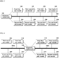
- FIGS. 1 and 2 are block diagrams for explaining an inner vehicle communication method according to the prior art.
- ECU electronice control unit
- FIG. 1 a structure is adopted, in which the electronic control unit 10 and a plurality of electronic devices installed in the vehicle individually transmit and receive signals.
- a first-first sub-module to a first-fourth sub-module 11, 12, 13, and 14 and a second-first sub-module to a second-fourth sub-module 21, 22, 23, and 24 mean a plurality of electronic devices; a first-first sub-module to a first-fourth sub-module 11, 12, 13, and 14 mean a group of the same type of electronic device; and a second-first sub-module to second-fourth sub-module 21, 22, 23, and 24 may mean another group of the same type of electronic device.
- the electronic control unit 10 may sequentially transmit and receive signals to and from each of the sub-modules 11, 12, 13, 14, 21, 22, 23, and 24 rather than transmitting signals individually.
- communication takes place in a way that when the electronic control unit 10 transmits a signal A to a first-first sub-module 11; the first-first sub-module 11 receives it and then transmits the signal A to the next module which is a first-second sub-module 12; the first-second sub-module 12 transmits the signal A to a first-third sub-module 13; and the first-third sub-module 13 transmits the signal A to a first-fourth sub-module 14.
- FIG. 3 is a block diagram illustrating a partial configuration of a vehicle inner communication system according to an embodiment
- FIG. 4 is a block diagram illustrating a modified embodiment of a vehicle inner communication system according to an embodiment of FIG. 3 .
- a first-first sub-module to a first-fourth sub-module 110, 120, 130, and 140 and a second-first sub-module to a second-fourth sub-module 210, 220, 230, and 240 mean a plurality of electronic devices; a first-first sub-module to a first-fourth sub-module 110, 120, 130, and 140 mean a group of the same type of electronic device; and the second-first sub-module to the second-fourth sub-module 210, 220, 230, and 240 mean another group of the same type of electronic device.
- FIG. 3 a first-first sub-module to a first-fourth sub-module 110, 120, 130, and 140 and a second-first sub-module to a second-fourth sub-module 210, 220, 230, and 240 mean another group of the same type of electronic device.
- a 3-1 sub-module 310 and a 3-2 sub-module 320 mean a group of the same type of electronic device
- a 4-1 sub-module 410 and a 4-2 sub-module 420 mean another group of the same type of electronic device.
- an electronic control unit is a device corresponding to the ECU of the vehicle, and will be described with reference to a control unit 100 for convenience of description below.
- the sub-module group is described based on the first module and the second module, but it is not limited thereto, and as illustrated in FIG. 4 , more types of modules may be set, and the number of modules may also be variously changed.
- control unit 100 may transmit and receive a communication signal to and from a first-first sub-module to a first-fourth sub-modules 110, 120, 130, and 140 and a second-first sub-module to a second-fourth sub-module 210, 220, 230, and 240 through two methods.
- control unit 100 can communicate individually with each of the first-first sub-module to the first-fourth sub-module 110, 120, 130, and 140 and a second-first sub-module to a second-fourth sub-module 210, 220, 230, and 240, and at the same time, may perform communication separately and sequentially with a first-first sub-module to a first-fourth sub-module 110, 120, 130, and 140 and a second-first sub-module to a second-fourth sub-module 210, 220, 230, and 240 through serially connected communication lines.
- CAN communication and RS-485 communication methods generally used inside the vehicle may be included; and in case of serial communication method, UART (universal asynchronous receiver/transmitter) communication method, RS-232 communication method, SPI communication method, I2C communication method, and the like may be included.
- UART universal asynchronous receiver/transmitter
- the control unit 100 should detect the status information of each module and perform control if necessary, and in general, the state of the modules can be detected using the BUS communication line 200.
- the control unit 100 can perform dual communication in controlling the module, so there is an effect that can enhance the operational stability of the modules installed in a vehicle.
- control unit 100 may control various modules installed in the vehicle using the bus communication line 200, and in the case of bus communication lines, since it uses a common communication line 200 as indicated in the drawing, rather than using one individual line, so there is an advantage of being able to transmit a signal to each module simultaneously.
- the vehicle inner communication system it is possible to communicate with the module in a serial connection communication method separately from the bus communication method, and since the control unit 100 can determine the location of each module using communication and proceed with setting, the problem that the position of the module has to be fixed can disappear, and furthermore, there is an advantage that only one sub-module needs to be managed per module.
- ID setting for each module had to be performed using bus communication, but in the case of a vehicle inner communication system according to an embodiment, since ID setting can be set using serially connected communication, ID setting can be performed more efficiently, and at the same time, there is also the effect that the location constraint for each module is removed.
- a vehicle inner communication system can continuously control the module even if a communication problem occurs in any one of the bus communication method and the serial communication method, so communication with each module can be performed using another communication method, and due to this, there is an advantage of obtaining a higher safety rating of the vehicle capable of stably operating various modules installed in the vehicle.
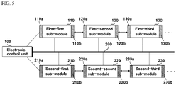
- FIG. 5 is a block diagram illustrating a partial configuration of a vehicle inner communication system according to yet another embodiment.
- FIG. 5 a general structure and a method of performing communication are the same as those of FIG. 3 , so overlapping portions will be omitted and characteristics between modules will be described.
- the controller 100 may set the same type of modules to a same group when setting the modules installed in the vehicle for each group.
- a DC-DC converter system converters can be set to the same group; also in a battery management system, batteries can be set to the same group; and also in an oil circuit breaker (OCB) system, breakers and the like can be set to the same group, and in this case, modules of the same type can communicate with each other in the same way.
- OBC oil circuit breaker
- the receiving unit 110a in which the first-first sub-module 110 receives a signal from the control unit 100 and the transmitting unit 110b transmitting to the first-second sub-module 120 may be configured with the same type of communication interface. That is, the transmitting unit 110a of the first-first sub-module 110 and the receiving unit 110b; the transmitting unit 120a and the receiving unit 120b of the first-second sub-module 120; and the transmitting unit 130a and the receiving unit 130b of the first-third sub-module 130 may be configured with the same type of communication interface.
- the receiving unit 210a that the second-first sub-module 210 receives a signal from the control unit 100 and the transmitting unit 210b that transmits to the second-second sub-module 220 may be configured with the same type of communication interface. That is, the transmitting unit 210a and the receiving unit 210b of the second-first sub-module 210; the transmitting unit 220a and the receiving unit 220b of the second-second sub-module 220; and the transmitting unit 230a and the receiving unit 230b of the second-third sub-module 230 may be configured with the same type of communication interface.
- a vehicle inner communication system and vehicle including same has an effect of reducing restrictions on arrangement positions of electronic devices by setting an ID to each of the electronic devices, which is a disadvantage of bus communication, by using serial-connected communication.
- a vehicle inner communication system and vehicle including same can continuously control electronic devices using another communication method even if operation is impossible due to a problem in one communication, and thus, there is an effect of achieving a higher safety rating for the vehicle by implementing dual communication from a functional safety point of view.
Landscapes
- Engineering & Computer Science (AREA)
- Computer Networks & Wireless Communication (AREA)
- Signal Processing (AREA)
- Theoretical Computer Science (AREA)
- Physics & Mathematics (AREA)
- General Engineering & Computer Science (AREA)
- General Physics & Mathematics (AREA)
- Small-Scale Networks (AREA)
- Health & Medical Sciences (AREA)
- Computing Systems (AREA)
- General Health & Medical Sciences (AREA)
- Medical Informatics (AREA)
Abstract
Description
- The present invention relates to a vehicle inner communication system and vehicle including same, and more particularly, relates to a technology for efficiently performing communication between a main controller inside a vehicle and various modules installed inside the vehicle.
- In modern society, automobiles are the most common means of transportation, and the number of people using automobiles is increasing. Owing to the development of automobile technology, many changes are taking place in life, such as making it easier to move long distances than in the past and making life easier.
- For the convenience of the driver, many electronic devices such as hands-free devices, GPS receivers, Bluetooth devices, and high-pass devices are being developed inside vehicles, and among automobile-related technology fields, the proportion of electric and electronic fields creating new values is increasing.
- Recently, many electronic device parts are mounted in automobiles, and many electronic device parts are being operated multiple times and simultaneously. In general, in such a case, one central electronic control unit (ECU) for a vehicle plays the role of managing and controlling these electronic parts at the same time.
- However, in installing and controlling these electronic device components, since it is efficient to install and control similar types of electronic device components as a group, recently, attempts to diversify product groups by connecting devices such as a DC-DC converter or an oil circuit breaker (OCB) are actively being made.
- However, in the case of adopting such a configuration, the central electronic control unit must be able to detect in real time whether various electronic device components connected to the central electronic control unit are operating correctly, however, in the case of the prior art, when a problem occurs in a portion of the communication line connected between the central electronic control device and the modules, thereby disabling communication, there is a problem that there is no way to accurately know this.
- Accordingly, the present invention is an invention devised to solve the problems of the prior art as described above, an object thereof is to provide a vehicle inner communication system and vehicle including same in which a method of communication with electronic devices using a bus and a communication method of electronic devices connected in series by controlling electronic devices using both at the same time, so that when a problem occurs in one communication method, it is possible to control electronic devices using other methods of communication.
- A vehicle inner communication system according to one embodiment may comprise: a plurality of electronic device groups provided in a vehicle; and a control unit configured to detect electronic devices in the electronic device groups and control operation thereof, by using bus communication method, which send and receive signal individually with electronic devices in the electronic device groups, and serial communication method, which send and receive signal sequentially with electronic devices serially connected in the electronic device group.
- The bus communication method may include at least one of a controller area network (CAN) communication method and an RS-485 communication method.
- The serial communication method may include a method in which communication signals are sequentially transmitted through serially connected electronic devices.
- The serial communication method may include at least one among a universal asynchronous receiver/transmitter (UART) communication method, an RS-232 communication method, an SPI communication method, and an I2C communication method.
- The control unit sets IDs to the electronic devices inside the electronic device group using the serial communication method, and then may detect the electronic devices through the bus communication method using the IDs that has been set and control the operation thereof.
- In the electronic device group, electronic devices of the same type may be grouped together.
- Electronic devices in the electronic device group may transmit/receive signals to each other using the same type of communication method.
- The electronic devices may include at least one among a DC-DC converter, a battery management system, and an oil circuit breaker (OCB).
- The control unit may detect and control the electronic devices using another communication method that is operating normally when a problem occurs in the operation of any one of the bus communication method and the serial communication method.
- A vehicle according to another embodiment may comprises: at least one of electronic device groups; and a control unit configured to detect electronic devices in the electronic device groups and control operation thereof, by using bus communication method individually connected to electronic devices in the electronic device group and serial communication method which the electronic devices in the electronic device group are connected each other.
- A vehicle inner communication system and vehicle including same according to an embodiment has an effect of reducing restrictions on arrangement positions of electronic devices by setting an ID to each of the electronic devices, which is a disadvantage of bus communication, by using serial-connected communication.
- In addition, a vehicle inner communication system and vehicle including same according to an embodiment can continuously control electronic devices using another communication method even if operation is impossible due to a problem in one communication, and thus, there is an effect of achieving a higher safety rating for the vehicle by implementing dual communication from a functional safety point of view.
-
-
FIG. 1 is a block diagram illustrating a communication method inside a vehicle according to a prior art. -
FIG. 2 is a block diagram for explaining a communication method inside a vehicle according to another prior art. -
FIG. 3 is a block diagram illustrating a partial configuration of a vehicle inner communication system according to an embodiment. -
FIG. 4 is a block diagram illustrating a partial configuration of a vehicle inner communication system according to another embodiment. -
FIG. 5 is a block diagram illustrating a partial configuration of a vehicle inner communication system according to yet another embodiment. - The configuration illustrated in the embodiments and drawings described in this specification are a preferred example of the disclosed invention, and there may be various modified embodiments that may replace the embodiments and drawings of the present specification at the time of filing of the present application.
- In addition, the terms used in this specification are used to describe the embodiments, and are not intended to limit and/or restrict the disclosed invention. The singular expression includes the plural expression unless the context clearly dictates otherwise.
- In the present specification, terms such as "comprises", "comprising" or "have" are intended to designate that the features, numbers, steps, operations, components, parts, or combinations thereof described in the specification exist, but does not preclude in advance the possibility of the presence or addition of one or more other features or numbers, steps, operations, components, parts, or combinations thereof, and terms including an ordinal number such as "first", "second", and the like used in this specification may be used to describe various components, but the components are not limited by the terms.
- Hereinafter, with reference to the accompanying drawings, embodiments of the present invention will be described in detail so that those of ordinary skill in the art can easily carry out the present invention. And in order to clearly explain the present invention in the drawings, parts irrelevant to the description will be omitted.
-
FIGS. 1 and 2 are block diagrams for explaining an inner vehicle communication method according to the prior art. - Many electronic device components are mounted on a vehicle for the operation of the vehicle and the convenience of the user, and the state of these electronic device components is detected through an electronic control unit (ECU), which is generally installed inside the vehicle, and operation is controlled at the same time.
- And with the development of electronic technology, the number and types of electronic device components mounted on vehicles are increasing, and since managing all of these individually by the electronic control unit may result in an overload of the electronic control unit, there is a growing need for a method capable of efficiently managing these electronic devices.
- Accordingly, in order for the electronic control unit of the vehicle to efficiently manage electronic device components mounted on the vehicle, it should be possible to determine in real time whether the transmission and reception of signals between the electronic control unit and the electronic devices are operating smoothly and without any problems, but in the case of prior art, since there is only one way of communication between the electronic control unit and the electronic devices, there has been a problem in which this could not be accurately determined.
- Looking at this in detail, in the case of the prior art, as illustrated in
FIG. 1 , a structure is adopted, in which theelectronic control unit 10 and a plurality of electronic devices installed in the vehicle individually transmit and receive signals. - Here, a first-first sub-module to a first-
fourth sub-module fourth sub-module fourth sub-module fourth sub-module - That is, in the case of the prior art, since the
electronic control unit 10 controlled each of thesub-modules sub-modules - In addition, in the case of the prior art, a structure as illustrated in
FIG. 2 is adopted as another method, and in the case of the structure illustrated inFIG. 2 , theelectronic control unit 10 may sequentially transmit and receive signals to and from each of thesub-modules - Specifically, in the case of such a communication method, electronic devices of the same type are sequentially connected to form a group, and communication is performed in such a way that a received signal is transmitted to the next serially connected module.
- For example, communication takes place in a way that when the
electronic control unit 10 transmits a signal A to a first-first sub-module 11; the first-first sub-module 11 receives it and then transmits the signal A to the next module which is a first-second sub-module 12; the first-second sub-module 12 transmits the signal A to a first-third sub-module 13; and the first-third sub-module 13 transmits the signal A to a first-fourth sub-module 14. - In the case of such a communication method, there is an advantage of being able to transmit and receive signals more efficiently as the modules of the same group are connected to each other, but as the number of connected modules increases, the communication time becomes longer, and when a problem occurs in any one communication line, there may be a problem in that communication to all modules connected in series becomes impossible.
- Therefore, in the case of the vehicle inner communication system and vehicle including same according to an embodiment, it is to provide a method capable of stably enhancing the communication performance inside the vehicle while solving these problems. Hereinafter, it will be studied in detail through the drawings.
-
FIG. 3 is a block diagram illustrating a partial configuration of a vehicle inner communication system according to an embodiment, andFIG. 4 is a block diagram illustrating a modified embodiment of a vehicle inner communication system according to an embodiment ofFIG. 3 . - In
FIG. 3 , a first-first sub-module to a first-fourth sub-module fourth sub-module fourth sub-module fourth sub-module FIG. 4 , a 3-1sub-module 310 and a 3-2sub-module 320 mean a group of the same type of electronic device, and a 4-1sub-module 410 and a 4-2sub-module 420 mean another group of the same type of electronic device. - In addition, an electronic control unit is a device corresponding to the ECU of the vehicle, and will be described with reference to a
control unit 100 for convenience of description below. InFIG. 3 , the sub-module group is described based on the first module and the second module, but it is not limited thereto, and as illustrated inFIG. 4 , more types of modules may be set, and the number of modules may also be variously changed. - Referring to
FIG. 3 , thecontrol unit 100 may transmit and receive a communication signal to and from a first-first sub-module to a first-fourth sub-modules fourth sub-module - Specifically, the
control unit 100 can communicate individually with
each of the first-first sub-module to the first-fourth sub-module fourth sub-module fourth sub-module fourth sub-module - Here, in the case of the
bus communication line 200, CAN communication and RS-485 communication methods generally used inside the vehicle may be included; and in case of serial communication method, UART (universal asynchronous receiver/transmitter) communication method, RS-232 communication method, SPI communication method, I2C communication method, and the like may be included. - The
control unit 100 should detect the status information of each module and perform control if necessary, and in general, the state of the modules can be detected using theBUS communication line 200. - And in this case, a separate setting is required for each module, and such information can be set using a communication line connected in series with the
control unit 100. - Therefore, since the vehicle inner communication system according to an embodiment has such a configuration, the
control unit 100 can perform dual communication in controlling the module, so there is an effect that can enhance the operational stability of the modules installed in a vehicle. - In addition, the
control unit 100 may control various modules installed in the vehicle using thebus communication line 200, and in the case of bus communication lines, since it uses acommon communication line 200 as indicated in the drawing, rather than using one individual line, so there is an advantage of being able to transmit a signal to each module simultaneously. - In addition, when communication is performed using bus communication, even if one module fails, this problem does not interfere with communication between other modules, so there is an advantage in that communication with other modules can be stably performed.
- However, when communication is performed using only the bus communication line, due to the nature of bus communication, a predefined ID is required for each module, but when only the bus communication line is used, there is a problem that the position of the module must be fixed in response thereto.
- However, in the case of the vehicle inner communication system according to an embodiment, it is possible to communicate with the module in a serial connection communication method separately from the bus communication method, and since the
control unit 100 can determine the location of each module using communication and proceed with setting, the problem that the position of the module has to be fixed can disappear, and furthermore, there is an advantage that only one sub-module needs to be managed per module. - In addition, when performing communication using bus communication, there were many problems as the ID setting for each module had to be performed using bus communication, but in the case of a vehicle inner communication system according to an embodiment, since ID setting can be set using serially connected communication, ID setting can be performed more efficiently, and at the same time, there is also the effect that the location constraint for each module is removed.
- In addition, a vehicle inner communication system according to an embodiment can continuously control the module even if a communication problem occurs in any one of the bus communication method and the serial communication method, so communication with each module can be performed using another communication method, and due to this, there is an advantage of obtaining a higher safety rating of the vehicle capable of stably operating various modules installed in the vehicle.
-
FIG. 5 is a block diagram illustrating a partial configuration of a vehicle inner communication system according to yet another embodiment. - Referring to
FIG. 5 , a general structure and a method of performing communication are the same as those ofFIG. 3 , so overlapping portions will be omitted and characteristics between modules will be described. - The
controller 100 according to an embodiment may set the same type of modules to a same group when setting the modules installed in the vehicle for each group. For example, in a DC-DC converter system, converters can be set to the same group; also in a battery management system, batteries can be set to the same group; and also in an oil circuit breaker (OCB) system, breakers and the like can be set to the same group, and in this case, modules of the same type can communicate with each other in the same way. - Specifically, as illustrated in
FIG. 5 ,the receivingunit 110a in which the first-first sub-module 110 receives a signal from thecontrol unit 100 and the transmittingunit 110b transmitting to the first-second sub-module 120 may be configured with the same type of communication interface. That is, the transmittingunit 110a of the first-first sub-module 110 and the receivingunit 110b; the transmittingunit 120a and the receivingunit 120b of the first-second sub-module 120; and the transmittingunit 130a and the receivingunit 130b of the first-third sub-module 130 may be configured with the same type of communication interface. - Similarly, the receiving
unit 210a that the second-first sub-module 210 receives a signal from thecontrol unit 100 and the transmittingunit 210b that transmits to the second-second sub-module 220 may be configured with the same type of communication interface. That is, the transmittingunit 210a and the receivingunit 210b of the second-first sub-module 210; the transmittingunit 220a and the receivingunit 220b of the second-second sub-module 220; and the transmittingunit 230a and the receivingunit 230b of the second-third sub-module 230 may be configured with the same type of communication interface. - In addition, in the case of having such a configuration, since the ID setting, which is a disadvantage of communication using bus communication of the prior art, can be effectively set using serial-connected communication, the effect of reducing the restrictions on the positional arrangement of the module may occur.
- Up to now, the configuration and effects of a vehicle inner communication system have been studied through drawings.
- In the case of a vehicle inner communication system according to the prior art, there was a problem that there was no way to accurately know when a problem occurred in a part of the connected communication line and communication is not established.
- However, a vehicle inner communication system and vehicle including same according to an embodiment has an effect of reducing restrictions on arrangement positions of electronic devices by setting an ID to each of the electronic devices, which is a disadvantage of bus communication, by using serial-connected communication.
- In addition, a vehicle inner communication system and vehicle including same according to an embodiment can continuously control electronic devices using another communication method even if operation is impossible due to a problem in one communication, and thus, there is an effect of achieving a higher safety rating for the vehicle by implementing dual communication from a functional safety point of view.
- Although the embodiments have been described with reference to the limited embodiments and drawings up to now, various modifications and variations are possible from the above description by those skilled in the art. For example, the techniques described may be performed in a different order than the method described, and/or components of the described system, structure, device, circuit, and the like are combined or combined in a manner different from the described method, or even if replaced or substituted by other components or equivalents, appropriate results can be achieved. Therefore, other embodiments and equivalents to the claims also belong to the scope of the claims described below.
Claims (10)
- A vehicle inner communication system comprising:at least one of electronic device group provided in a vehicle; anda control unit configured to detect electronic devices in the electronic device group and control operation thereof, by using bus communication method, which send and receive signal individually with electronic devices in the electronic device group, and serial communication method, which send and receive signal sequentially with electronic devices serially connected in the electronic device group.
- The vehicle inner communication system according to claim 1, wherein the bus communication method comprises at least one of a controller area network (CAN) communication method and an RS-485 communication method.
- The vehicle inner communication system according to claim 1, wherein the serial communication method comprises a method in which communication signals are sequentially transmitted through electronic devices serially connected.
- The vehicle inner communication system according to claim 1, wherein the serial communication method comprises at least one among a universal asynchronous receiver/transmitter (UART) communication method, an RS-232 communication method, an SPI communication method, and an I2C communication method.
- The vehicle inner communication system according to claim 1, wherein the control unit sets IDs to electronic devices in the electronic device group using the serial communication method, and then detects the electronic devices through the bus communication method using the IDs that has been set and controls the operation thereof.
- The vehicle inner communication system according to claim 1, wherein in the electronic device group, electronic devices of same type are grouped together.
- The vehicle inner communication system according to claim 6, wherein electronic devices in the electronic device group transmit/receive signals to each other using same type of communication method.
- The vehicle inner communication system according to claim 1, wherein the electronic devices comprises at least one among a DC-DC converter, a battery management system, and an oil circuit breaker (OCB).
- The vehicle inner communication system according to claim 1, wherein the control unit detects and controls the electronic devices using another communication method that is operating normally when a problem occurs in the operation of any one of the bus communication method and the serial communication method.
- A vehicle comprising:at least one of electronic device group; anda control unit configured to detect electronic devices in the electronic device group and control operation thereof, by using bus communication method individually connected to electronic devices in the electronic device group and serial communication method which the electronic devices in the electronic device group are connected each other.
Applications Claiming Priority (2)
| Application Number | Priority Date | Filing Date | Title |
|---|---|---|---|
| KR1020190111748A KR102820281B1 (en) | 2019-09-09 | 2019-09-09 | An in-vehicle communication system and a vehicle comprising the same. In-vehicle |
| PCT/KR2020/012188 WO2021049879A1 (en) | 2019-09-09 | 2020-09-09 | Vehicle inner communication system and vehicle including same |
Publications (3)
| Publication Number | Publication Date |
|---|---|
| EP4030699A1 true EP4030699A1 (en) | 2022-07-20 |
| EP4030699A4 EP4030699A4 (en) | 2022-11-02 |
| EP4030699B1 EP4030699B1 (en) | 2025-12-17 |
Family
ID=74866695
Family Applications (1)
| Application Number | Title | Priority Date | Filing Date |
|---|---|---|---|
| EP20862086.4A Active EP4030699B1 (en) | 2019-09-09 | 2020-09-09 | Vehicle inner communication system and vehicle including same |
Country Status (6)
| Country | Link |
|---|---|
| US (1) | US12155503B2 (en) |
| EP (1) | EP4030699B1 (en) |
| JP (1) | JP7634521B2 (en) |
| KR (1) | KR102820281B1 (en) |
| CN (1) | CN114365457B (en) |
| WO (1) | WO2021049879A1 (en) |
Families Citing this family (1)
| Publication number | Priority date | Publication date | Assignee | Title |
|---|---|---|---|---|
| KR20230105597A (en) * | 2022-01-04 | 2023-07-11 | 주식회사 엘지에너지솔루션 | Communication device for vehicle and operating method thereof |
Family Cites Families (20)
| Publication number | Priority date | Publication date | Assignee | Title |
|---|---|---|---|---|
| SE0001491D0 (en) * | 2000-04-25 | 2000-04-25 | Scania Cv Ab | Functionally divided deplex communication bus |
| US6996644B2 (en) | 2001-06-06 | 2006-02-07 | Conexant Systems, Inc. | Apparatus and methods for initializing integrated circuit addresses |
| US7170853B2 (en) * | 2001-08-31 | 2007-01-30 | Temic Automotive Of North America, Inc. | Vehicle active network topologies |
| JP4826885B2 (en) * | 2005-09-29 | 2011-11-30 | 日本精機株式会社 | Control device for vehicle display |
| JP2009135693A (en) | 2007-11-29 | 2009-06-18 | Toyota Motor Corp | Vehicle control system |
| KR20090084361A (en) * | 2008-02-01 | 2009-08-05 | 현대로템 주식회사 | Bus-type Train Control Network Using Arcnet Communication |
| DE102008050102B4 (en) * | 2008-10-06 | 2010-11-04 | Phoenix Contact Gmbh & Co. Kg | Communication entity for communication via a bus-oriented communication network |
| KR20110085679A (en) * | 2010-01-21 | 2011-07-27 | 글로컴비즈코리아주식회사 | Automobile self-diagnosis device using hybrid communication of Zigbee communication and CAN communication |
| US9843172B2 (en) * | 2014-12-31 | 2017-12-12 | Lsis Co., Ltd. | Switchboard with position-indicating apparatus |
| KR101749390B1 (en) * | 2015-01-28 | 2017-06-20 | 주식회사 엘지화학 | System for Controller Area Network and CAN Communication Apparatus |
| EP3326312B1 (en) | 2015-07-22 | 2025-10-01 | Arilou Information Security Technologies Ltd. | Vehicle communications bus data security |
| US20170083468A1 (en) * | 2015-09-21 | 2017-03-23 | Qualcomm Incorporated | Identifying multiple identical devices on a shared bus |
| KR101714474B1 (en) * | 2016-01-06 | 2017-03-09 | 현대자동차주식회사 | Communication method of electronic device in vehicle and vehicle having the same |
| US10509407B2 (en) | 2016-07-01 | 2019-12-17 | Samsung Electronics Co., Ltd. | Apparatus and method for a vehicle platform |
| CN106230648B (en) * | 2016-09-14 | 2023-02-17 | 南京康尼机电股份有限公司 | Gate controller of integrated data acquisition and transmission device and processing and transmission method thereof |
| JP6493381B2 (en) | 2016-12-26 | 2019-04-03 | トヨタ自動車株式会社 | In-vehicle communication system |
| EP3635565B1 (en) * | 2017-05-15 | 2023-10-11 | Apex Industrial Technologies LLC | Sequential node identification in multiple-compartment dispensing enclosures |
| US10789364B2 (en) * | 2018-05-02 | 2020-09-29 | Nxp B.V. | Method for providing an authenticated update in a distributed network |
| JP2020154584A (en) * | 2019-03-19 | 2020-09-24 | キオクシア株式会社 | Memory system |
| US11815976B2 (en) * | 2019-05-22 | 2023-11-14 | Qualcomm Incorporated | Bandwidth based power management for peripheral component interconnect express devices |
-
2019
- 2019-09-09 KR KR1020190111748A patent/KR102820281B1/en active Active
-
2020
- 2020-09-09 CN CN202080064079.8A patent/CN114365457B/en active Active
- 2020-09-09 EP EP20862086.4A patent/EP4030699B1/en active Active
- 2020-09-09 JP JP2022515582A patent/JP7634521B2/en active Active
- 2020-09-09 US US17/637,629 patent/US12155503B2/en active Active
- 2020-09-09 WO PCT/KR2020/012188 patent/WO2021049879A1/en not_active Ceased
Also Published As
| Publication number | Publication date |
|---|---|
| CN114365457B (en) | 2024-06-18 |
| WO2021049879A1 (en) | 2021-03-18 |
| JP2022547190A (en) | 2022-11-10 |
| US20220278869A1 (en) | 2022-09-01 |
| US12155503B2 (en) | 2024-11-26 |
| KR102820281B1 (en) | 2025-06-16 |
| JP7634521B2 (en) | 2025-02-21 |
| CN114365457A (en) | 2022-04-15 |
| EP4030699B1 (en) | 2025-12-17 |
| EP4030699A4 (en) | 2022-11-02 |
| KR20210030154A (en) | 2021-03-17 |
Similar Documents
| Publication | Publication Date | Title |
|---|---|---|
| US20110164594A1 (en) | Device and method for transmitting information | |
| US20190012916A1 (en) | Motor vehicle and parking lot for motor vehicles as well as communications system | |
| WO2012018033A1 (en) | Processing system, processing device and power supply control method | |
| EP2654171B1 (en) | Power supply device and power supply method | |
| AU2011348866B2 (en) | Computer-control method for multi-unit coupling of a rail locomotive | |
| WO2014104168A1 (en) | Vehicle communication system, onboard device, memory medium, and communication method | |
| KR102174402B1 (en) | Battery charging status indicator system for electric vehicle and control method for the same | |
| US12155503B2 (en) | Vehicle inner communication system and vehicle including same | |
| US20250010748A1 (en) | Method and apparatus for wireless charging of stopped and driving electric vehicles using two-way communications | |
| CN110562275B (en) | Multichannel dual-redundancy rail transit vehicle reconnection system and method | |
| US10004024B2 (en) | Method and apparatus for varied-host shared vehicular remote connectivity | |
| CN111854805B (en) | Detection circuit and method for external antenna | |
| US9660705B2 (en) | On-board unit, communication method, and recording medium | |
| JP2014068466A (en) | Charge device | |
| JP4455946B2 (en) | On-board information control system | |
| US20110222433A1 (en) | Automatic address configuration of vehicle network devices during installation | |
| KR102469911B1 (en) | Wireless power transmission module and method for providing service using the same | |
| WO2025029041A1 (en) | Vehicle charging device | |
| EP3223423B1 (en) | Power generator system, power generator control device, and power-generation balance control method for power generator system | |
| EP4109768A1 (en) | Modulation of supply current in active antenna systems | |
| JP2008299498A (en) | Detection method of overhead wire cut | |
| WO2022194129A1 (en) | Control system, vehicle-mounted control apparatus and autonomous vehicle | |
| US20160339933A1 (en) | Communication device, train network system, and network setting method | |
| US12316551B2 (en) | Method for transmitting a data element between a first control unit of a vehicle and a second control unit of the vehicle, computer-readable medium, system and vehicle | |
| KR102711330B1 (en) | Electronic controller unit, System for controlling vehicle, and system for sensing information about the vehicle |
Legal Events
| Date | Code | Title | Description |
|---|---|---|---|
| STAA | Information on the status of an ep patent application or granted ep patent |
Free format text: STATUS: THE INTERNATIONAL PUBLICATION HAS BEEN MADE |
|
| PUAI | Public reference made under article 153(3) epc to a published international application that has entered the european phase |
Free format text: ORIGINAL CODE: 0009012 |
|
| STAA | Information on the status of an ep patent application or granted ep patent |
Free format text: STATUS: REQUEST FOR EXAMINATION WAS MADE |
|
| 17P | Request for examination filed |
Effective date: 20220304 |
|
| AK | Designated contracting states |
Kind code of ref document: A1 Designated state(s): AL AT BE BG CH CY CZ DE DK EE ES FI FR GB GR HR HU IE IS IT LI LT LU LV MC MK MT NL NO PL PT RO RS SE SI SK SM TR |
|
| A4 | Supplementary search report drawn up and despatched |
Effective date: 20221005 |
|
| RIC1 | Information provided on ipc code assigned before grant |
Ipc: G06F 13/42 20060101ALI20220928BHEP Ipc: H04L 12/40 20060101AFI20220928BHEP |
|
| DAV | Request for validation of the european patent (deleted) | ||
| DAX | Request for extension of the european patent (deleted) | ||
| STAA | Information on the status of an ep patent application or granted ep patent |
Free format text: STATUS: EXAMINATION IS IN PROGRESS |
|
| 17Q | First examination report despatched |
Effective date: 20240802 |
|
| GRAP | Despatch of communication of intention to grant a patent |
Free format text: ORIGINAL CODE: EPIDOSNIGR1 |
|
| STAA | Information on the status of an ep patent application or granted ep patent |
Free format text: STATUS: GRANT OF PATENT IS INTENDED |
|
| INTG | Intention to grant announced |
Effective date: 20250710 |
|
| GRAS | Grant fee paid |
Free format text: ORIGINAL CODE: EPIDOSNIGR3 |
|
| GRAA | (expected) grant |
Free format text: ORIGINAL CODE: 0009210 |
|
| STAA | Information on the status of an ep patent application or granted ep patent |
Free format text: STATUS: THE PATENT HAS BEEN GRANTED |
|
| AK | Designated contracting states |
Kind code of ref document: B1 Designated state(s): AL AT BE BG CH CY CZ DE DK EE ES FI FR GB GR HR HU IE IS IT LI LT LU LV MC MK MT NL NO PL PT RO RS SE SI SK SM TR |
|
| REG | Reference to a national code |
Ref country code: CH Ref legal event code: F10 Free format text: ST27 STATUS EVENT CODE: U-0-0-F10-F00 (AS PROVIDED BY THE NATIONAL OFFICE) Effective date: 20251217 Ref country code: GB Ref legal event code: FG4D |
|
| REG | Reference to a national code |
Ref country code: DE Ref legal event code: R096 Ref document number: 602020064161 Country of ref document: DE |
|
| REG | Reference to a national code |
Ref country code: LT Ref legal event code: MG9D |
|
| PG25 | Lapsed in a contracting state [announced via postgrant information from national office to epo] |
Ref country code: NO Free format text: LAPSE BECAUSE OF FAILURE TO SUBMIT A TRANSLATION OF THE DESCRIPTION OR TO PAY THE FEE WITHIN THE PRESCRIBED TIME-LIMIT Effective date: 20260317 |
|
| PG25 | Lapsed in a contracting state [announced via postgrant information from national office to epo] |
Ref country code: HR Free format text: LAPSE BECAUSE OF FAILURE TO SUBMIT A TRANSLATION OF THE DESCRIPTION OR TO PAY THE FEE WITHIN THE PRESCRIBED TIME-LIMIT Effective date: 20251217 Ref country code: FI Free format text: LAPSE BECAUSE OF FAILURE TO SUBMIT A TRANSLATION OF THE DESCRIPTION OR TO PAY THE FEE WITHIN THE PRESCRIBED TIME-LIMIT Effective date: 20251217 |
|
| PG25 | Lapsed in a contracting state [announced via postgrant information from national office to epo] |
Ref country code: RS Free format text: LAPSE BECAUSE OF FAILURE TO SUBMIT A TRANSLATION OF THE DESCRIPTION OR TO PAY THE FEE WITHIN THE PRESCRIBED TIME-LIMIT Effective date: 20260317 |
|
| REG | Reference to a national code |
Ref country code: NL Ref legal event code: MP Effective date: 20251217 |
|
| PG25 | Lapsed in a contracting state [announced via postgrant information from national office to epo] |
Ref country code: LV Free format text: LAPSE BECAUSE OF FAILURE TO SUBMIT A TRANSLATION OF THE DESCRIPTION OR TO PAY THE FEE WITHIN THE PRESCRIBED TIME-LIMIT Effective date: 20251217 |
|
| PG25 | Lapsed in a contracting state [announced via postgrant information from national office to epo] |
Ref country code: BG Free format text: LAPSE BECAUSE OF FAILURE TO SUBMIT A TRANSLATION OF THE DESCRIPTION OR TO PAY THE FEE WITHIN THE PRESCRIBED TIME-LIMIT Effective date: 20251217 |