EP4030638A1 - Optical submarine communication system, monitoring result conveyance method, and non-transitory computer-readable medium in which program is stored - Google Patents
Optical submarine communication system, monitoring result conveyance method, and non-transitory computer-readable medium in which program is stored Download PDFInfo
- Publication number
- EP4030638A1 EP4030638A1 EP20863156.4A EP20863156A EP4030638A1 EP 4030638 A1 EP4030638 A1 EP 4030638A1 EP 20863156 A EP20863156 A EP 20863156A EP 4030638 A1 EP4030638 A1 EP 4030638A1
- Authority
- EP
- European Patent Office
- Prior art keywords
- optical signal
- submarine
- monitoring
- submarine device
- monitoring result
- Prior art date
- Legal status (The legal status is an assumption and is not a legal conclusion. Google has not performed a legal analysis and makes no representation as to the accuracy of the status listed.)
- Withdrawn
Links
- 230000003287 optical effect Effects 0.000 title claims abstract description 304
- 238000012544 monitoring process Methods 0.000 title claims abstract description 267
- 238000004891 communication Methods 0.000 title claims abstract description 51
- 238000000034 method Methods 0.000 title claims description 36
- 230000008859 change Effects 0.000 claims description 13
- 230000008569 process Effects 0.000 claims description 4
- 239000000284 extract Substances 0.000 claims description 3
- 238000010586 diagram Methods 0.000 description 16
- 230000005540 biological transmission Effects 0.000 description 14
- 230000005856 abnormality Effects 0.000 description 13
- 101000786631 Homo sapiens Protein SYS1 homolog Proteins 0.000 description 12
- 102100025575 Protein SYS1 homolog Human genes 0.000 description 12
- 230000004044 response Effects 0.000 description 11
- 230000006870 function Effects 0.000 description 4
- 238000001228 spectrum Methods 0.000 description 4
- 230000015654 memory Effects 0.000 description 3
- 230000001902 propagating effect Effects 0.000 description 3
- 101150050673 CHK1 gene Proteins 0.000 description 2
- 230000015556 catabolic process Effects 0.000 description 2
- 238000006731 degradation reaction Methods 0.000 description 2
- 238000012545 processing Methods 0.000 description 2
- 239000004065 semiconductor Substances 0.000 description 2
- 230000008901 benefit Effects 0.000 description 1
- 238000004590 computer program Methods 0.000 description 1
- 238000013461 design Methods 0.000 description 1
- 230000000694 effects Effects 0.000 description 1
- 239000013307 optical fiber Substances 0.000 description 1
Images


Classifications
-
- H—ELECTRICITY
- H04—ELECTRIC COMMUNICATION TECHNIQUE
- H04B—TRANSMISSION
- H04B10/00—Transmission systems employing electromagnetic waves other than radio-waves, e.g. infrared, visible or ultraviolet light, or employing corpuscular radiation, e.g. quantum communication
- H04B10/07—Arrangements for monitoring or testing transmission systems; Arrangements for fault measurement of transmission systems
- H04B10/075—Arrangements for monitoring or testing transmission systems; Arrangements for fault measurement of transmission systems using an in-service signal
- H04B10/077—Arrangements for monitoring or testing transmission systems; Arrangements for fault measurement of transmission systems using an in-service signal using a supervisory or additional signal
-
- H—ELECTRICITY
- H04—ELECTRIC COMMUNICATION TECHNIQUE
- H04B—TRANSMISSION
- H04B13/00—Transmission systems characterised by the medium used for transmission, not provided for in groups H04B3/00 - H04B11/00
- H04B13/02—Transmission systems in which the medium consists of the earth or a large mass of water thereon, e.g. earth telegraphy
Definitions
- the present disclosure relates to a submarine optical communication system and a method of transmitting a monitoring result.
- the submarine optical communication system includes a plurality of terminal station apparatuses provided on land, a submarine cable for transmitting communication between the plurality of terminal station apparatuses, and a submarine device provided at a relay point of the submarine cable.
- the submarine device transmits, relays, and splits optical signals propagating through the submarine cable.
- the submarine device monitors an operation state of itself, and transmits a result of the monitoring to one of a plurality of the terminal station apparatuses having a function of managing the monitoring results among the plurality of terminal station apparatuses provided on land.
- Patent Literature 1, 2, and 3 Techniques related to a submarine optical communication system and a method of transmitting the monitoring results of the submarine device provided in the submarine optical communication system are disclosed in, for example, Patent Literature 1, 2, and 3.
- a terminal station apparatus transmits a command signal to a relay apparatus to be monitored, and in response to receiving the command signal, the relay apparatus to be monitored transmits a monitoring result of the relay apparatus itself to the terminal station apparatus as a response signal.
- the relay apparatus includes optical receiving means for receiving a wavelength-multiplexed optical signal, and processing means for selecting an optical signal in a first wavelength from the wavelength-multiplexed optical signal, performing intensity modulation according to notification information, returning the intensity-modulated optical signal back to the wavelength-multiplexed optical signal, and outputting the wavelength-multiplexed optical signal.
- the relay apparatus can output a monitoring optical signal (a monitoring result of the relay apparatus itself) without having a light source for the monitoring optical signal.
- the terminal station apparatus transmits a command signal to the relay apparatus to be monitored, and in response to receiving the command signal, the relay apparatus to be monitored transmits the monitoring result of the relay apparatus itself to the terminal station apparatus as a response signal. Therefore, in the configurations of Patent Literature 1 and 2, when there are a plurality of relay apparatuses to be monitored, it is necessary that the terminal station apparatus sequentially accesses each of the plurality of relay apparatuses to sequentially acquire the monitoring result of each of the plurality of relay apparatuses. In other words, it is necessary for each relay apparatus to transmit the monitoring result of the relay apparatus itself to the terminal station apparatus when the monitoring result is not transmitted by the other relay apparatuses. Specifically, in the configurations of Patent Literature 1 and 2, when there are a plurality of relay apparatuses to be monitored, the plurality of relay apparatuses cannot simultaneously transmit the monitoring results to the terminal station apparatus.
- a relay apparatus is merely configured to be able to adjust a modulation intensity of an optical signal in a designated wavelength for the purpose of outputting a monitoring optical signal (a monitoring result of the relay apparatus) without including a light source for the monitoring optical signal in the relay apparatus.
- a monitoring optical signal a monitoring result of the relay apparatus
- no consideration has been given to a case in which a plurality of relay apparatuses simultaneously transmit the monitoring results to the monitoring results.
- Patent Literature 3 when there are a plurality of relay apparatuses to be monitored, it is necessary for each relay apparatus to transmit the monitoring result of the relay apparatus itself when the monitoring results are not transmitted by the other relay apparatuses so that the transmission of the monitoring result does not collide with the transmission of the monitoring results by the other relay apparatuses. That is, in the configuration of Patent Literature 3, when there are a plurality of relay apparatuses to be monitored, the plurality of relay apparatuses cannot simultaneously transmit the monitoring results to the terminal station apparatus.
- Patent Literature 3 since an optically complicated circuit configuration is adopted in which a response signal light wavelength is split and extracted from a reception main signal by using a filter, modulated by VOA, and then multiplexed, there is a possibility that a main signal may be degraded. Additionally, this configuration require a dedicated circuit for light intensity modulation for a response. Further, since the optical wavelength used for the response cannot be changed in each splitter or repeater after the operation is started, a system including many optical branch apparatuses cannot support dynamic optical path changes. An amount of information that can be transmitted from each branch or repeater is also limited to binary information.
- An object of the present disclosure is to provide a submarine optical communication system and a method of transmitting a monitoring result that solve the above problems.
- An example aspect is a submarine optical communication system including: a plurality of terminal station apparatuses; a submarine cable configured to transmit optical signals used for communication between the plurality of terminal station apparatuses; and a first submarine device and a second submarine device provided at relay points of the submarine cable.
- the first submarine device includes: a first monitoring circuit configured to monitor an operation state of the first submarine device; and a first optical signal adjusting circuit configured to adjust an intensity of an optical signal in a first wavelength band assigned to the first submarine device among the optical signals supplied to the first submarine device based on a first monitoring result obtained by the first monitoring circuit and output the adjusted optical signal as an optical signal including the first monitoring result.
- the second submarine device includes: a second monitoring circuit configured to monitor an operation state of the second submarine device; and a second optical signal adjusting circuit configured to adjust an intensity of an optical signal in a second wavelength band assigned to the second submarine device among the optical signals supplied to the second submarine device based on a second monitoring result obtained by the second monitoring circuit and output the adjusted optical signal as an optical signal including the second monitoring result, the second wavelength band being different from the first wavelength band assigned to the first submarine device.
- a method of transmitting a monitoring result including: a first monitoring step of monitoring, in a first submarine device, an operation state of the first submarine device; a second monitoring step of monitoring, in a second submarine device, an operation state of the second submarine device; a first optical signal adjusting step of adjusting, in the first submarine device, an intensity of an optical signal in a first wavelength band assigned to the first submarine device among optical signals supplied to the first submarine device based on a first monitoring result obtained in the first monitoring step and outputting the adjusted optical signal as an optical signal including the first monitoring result; and a second optical signal adjusting step of adjusting, in the second submarine device, an intensity of an optical signal in a second wavelength band assigned to the second submarine device among the optical signals supplied to the second submarine device based on a second monitoring result obtained in the second monitoring step and outputting the adjusted optical signal as an optical signal including the second monitoring result, the second wavelength band being different from the first wavelength band assigned to the first submarine device.
- each of a plurality of submarine devices can freely transmit a monitoring result of the submarine device itself without worrying about each other's transmission state of a monitoring result, and a method of transmitting the monitoring result.
- components are not always essential unless otherwise particularly specified and considered to be definitely essential in principle.
- shapes, positional relations, or the like of the components or the like in the following example embodiment they will include ones, for example, substantially approximate or similar in their shapes or the like unless otherwise particularly specified and considered not to be definitely so in principle. This is similarly applied even to the above-described number or the like (including the number of pieces, numerical values, quantity, range, etc.).
- Fig. 1 is a block diagram schematically showing a submarine optical communication system SYS1 according to a first example embodiment.
- the submarine optical communication system SYS1 includes a plurality (four in the example of Fig. 1 ) of terminal station apparatuses 1, a plurality (two in the example of Fig. 1 ) of submarine devices 2, and submarine cables 3.
- the terminal station apparatuses 1 are referred to as terminal station apparatuses 1_1 to 1_4, respectively.
- the submarine devices 2 are referred to as submarine devices 2_1 and 2_2, respectively.
- the terminal station apparatuses 1_1 to 1_4 are provided on land and are configured to communicate with each other through the submarine cables 3. At least one of the terminal station apparatuses 1_1 to 1_4 has a function of collecting results of monitoring the submarine devices 2_1 and 2_2 performed by the submarine devices 2_1 and 2_2, respectively, and managing and controlling the monitoring results.
- Each of the submarine cables 3 transmits optical signals used for communication between the terminal station apparatuses 1_1 to 1_4.
- Each of the submarine devices 2_1 and 2_2 is provided at a relay point (on the bottom of the sea) of the submarine cable 3, and transmits, relays, and splits the optical signals propagating through the submarine cable 3.
- a monitoring circuit 211 monitors an operation state of the submarine device 2_1.
- the submarine device 2_1 includes at least the monitoring circuit 211 and an optical signal adjusting circuit 212.
- the optical signal adjusting circuit 212 adjusts an intensity of the optical signal in a wavelength band (a first wavelength band) assigned to the submarine device 2_1 among the optical signals (wavelength multiplexed optical signals) supplied to the submarine device 2_1 through the submarine cable 3, based on the monitoring result obtained by the monitoring circuit 211. Then, the optical signal adjusting circuit 212 outputs the adjusted optical signal as an optical signal including the monitoring result obtained by the monitoring circuit 211.
- This optical signal including the monitoring result obtained by the monitoring circuit 211 is transmitted through the submarine cable 3 to the terminal station apparatus (e.g., the terminal station apparatus 1_1) for managing and controlling the monitoring result of the submarine device 2_1.
- a monitoring circuit 221 monitors an operation state of the submarine device 2_2.
- the submarine device 2_2 includes at least the monitoring circuit 221 and an optical signal adjusting circuit 222.
- the optical signal adjusting circuit 222 adjusts an intensity of the optical signal in a wavelength band (a second wavelength band) assigned to the submarine device 2_2 among the optical signals (wavelength multiplexed optical signals) supplied to the submarine device 2_2 through the submarine cable 3, based on the monitoring result obtained by the monitoring circuit 221.
- the wavelength band of the optical signal assigned to the submarine device 2_2 is different from the wavelength band of the optical signal assigned to the submarine device 2_1.
- the optical signal adjusting circuit 222 outputs the adjusted optical signal as an optical signal including the monitoring result obtained by the monitoring circuit 221.
- This optical signal including the monitoring result obtained by the monitoring circuit 221 is transmitted through the submarine cable 3 to the terminal station apparatus (e.g., the terminal station apparatus 1_1) for managing and controlling the monitoring results of the submarine device 2_2.
- a plurality of submarine devices adjust the intensities of the optical signals in different wavelength bands included in common optical signals based on each of the monitoring results, and output the optical signals including the monitoring results, respectively.
- each of the plurality of submarine devices can freely transmit the monitoring result of the submarine device itself without worrying about each other's transmission state of the monitoring result. It is thus possible, for example, for the plurality of submarine devices to simultaneously transmit the respective monitoring results to the terminal station apparatus. Further, for example, when a failure occurs in any of the submarine devices, each of the submarine devices can autonomously transmit the monitoring result to the terminal station apparatus without waiting for a command signal from the terminal station apparatus. Furthermore, in this configuration, the configuration and assignment of the light wavelength and the like used for a response can be changed after the operation is started.
- the submarine device 2_2 has basically the same configuration as that of the submarine device 2_1 except that the wavelength band assigned to the submarine device 2_2 for transmitting the monitoring result is different from that assigned to the submarine device 2_1. Therefore, the description of the submarine device 2_2 will be omitted.
- the terminal station apparatuses 1_2 to 1_4 have basically the same configuration as that of the terminal station apparatus 1_1, and therefore, a description thereof will be omitted.
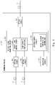
- Fig. 2 is a block diagram showing a specific configuration example of the submarine device 2_1.
- the submarine device 2_1 includes the monitoring circuit 211, the optical signal adjusting circuit 212, and optical circuits 215 to 217.
- the optical signal adjusting circuit 212 is composed of a spectrum control circuit 213 and an output light control circuit 214.
- the output light control circuit 214 has a function as a Wavelength Selectable Switch (WSS) for selecting one of a plurality of optical signals supplied from the plurality of submarine cables 3 of different paths and outputting the selected optical signal.
- WSS Wavelength Selectable Switch
- the output light control circuit 214 adjusts the intensity of the optical signal supplied through the submarine cable 3.
- the monitoring circuit 211 monitors the operation state of the submarine device 2_1.
- the operation state of the submarine device 2_1 includes status information, alarm information, monitor information, and the like of the submarine device 2_1.
- the spectrum control circuit 213 controls a spectrum (a wavelength intensity) of the optical signal output from the output light control circuit 214 based on the monitoring result obtained by the monitoring circuit 211.
- the output light control circuit 214 adjusts the intensity of the optical signal in the wavelength band assigned to the submarine device 2_1 among the optical signals to the intensity according to the monitoring result obtained by the monitoring circuit 211.
- An amount of adjustment of the intensity of the optical signal is controlled to such an extent that it does not affect communication quality.
- the predetermined wavelength band is excluded from the wavelength band used for transmitting the monitoring result.
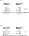
- Fig. 3 is a diagram for explaining the optical signal before the monitoring result of the submarine device 2_1 is transmitted by the submarine device 2_1.
- the optical signal propagating through the submarine cable 3 is, for example, a wavelength multiplexed optical signal composed of optical signals of a plurality of channels CH1 to CHk (k is an integer of two or more).
- Fig. 4 is a diagram for explaining a first method of transmitting the monitoring result of the submarine device 2_1 by the submarine device 2_1.
- the output light control circuit 214 adjusts the intensity of the optical signal of the channel CH2 assigned to the submarine device 2_1 among the optical signals based on the monitoring result obtained by the monitoring circuit 211. For example, when there is an abnormality in the submarine device 2_1, the output light control circuit 214 makes the intensity of the optical signal of the channel CH2 weaker than a reference intensity, while when there is no abnormality in the submarine device 2_1, the output light control circuit 214 makes the intensity of the optical signal of the channel CH2 stronger than the reference intensity.
- the channel CHk is assigned to the submarine device 2_2 as a channel for transmitting the monitoring result. Therefore, the submarine device 2_2 adjusts the intensity of the optical signal of the channel CHk based on the monitoring result obtained by the monitoring circuit 221.
- the submarine devices 2_1 and 2_2 adjust the intensities of the optical signals in different wavelength bands included in the common optical signals based on the respective monitoring results.
- each of the submarine devices 2_1 and 2_2 can freely transmit the monitoring result of the submarine devices 2_1 and 2_2, respectively, without worrying about each other's transmission state of the monitoring result.
- the intensity of the optical signal is controlled according to the monitoring result can be configured in any way. For example, when there is no abnormality in the submarine device 2_1, the intensity of the optical signal of the channel CH2 may be maintained at the reference intensity instead of making it stronger than the reference intensity. Alternatively, the intensity of the optical signal of the channel CH2 may be controlled only when a specific abnormality (a failure at a specific location) in the submarine device 2_1 occurs.
- Fig. 5 is a diagram for explaining a second method of transmitting the monitoring result of the submarine device 2_1 obtained by the submarine device 2_1.
- the output light control circuit 214 adjusts an amount of change of the optical signal of the channel CH2 from the reference intensity based on the monitoring result obtained by the monitoring circuit 211.
- the output light control circuit 214 adjusts the amount of change of the optical signal of the channel CH2 from the reference intensity based on the status information, the alarm information, and the monitor information of the submarine device 2_1.
- the submarine device 2_1 can collectively transmit a plurality of pieces of information included in the monitoring result obtained by the monitoring circuit 211.
- the channel CHk is assigned to the submarine device 2_2 as a channel for transmitting the monitoring result. Therefore, the submarine device 2_2 adjusts the amount of change of the optical signal of the channel CHk from the reference intensity based on the monitoring result obtained by the monitoring circuit 221. Thus, the submarine device 2_2 can collectively transmit a plurality of pieces of information included in the monitoring result obtained by the monitoring circuit 221.
- the submarine devices 2_1 and 2_2 adjust the amount of change of the optical signals of the channels CH2 and CHk from the reference intensity based on the monitoring results obtained by the submarine devices 2_1 and 2_2, respectively, but the present disclosure is not limited to this.
- the submarine devices 2_1 and 2_2 may adjust a period in which the intensities of the optical signals in the wavelength bands of the channels CH2 and CHk are changed based on the monitoring results obtained by the submarine devices 2_1 and 2_2, respectively.
- the submarine devices 2_1 and 2_2 may be capable of transmitting notifications about different monitoring results including an alarm or the like depending on a difference in a period of time during which the intensity of the optical signal is changed. For example, if the period of time during which the intensity of the optical signal is changed is 1 second, a first alarm A is indicated, while if the period of time during which the intensity of the optical signal is changed is 2 seconds, a second alarm B is indicated.
- Fig. 6 is a diagram for explaining a third method of transmitting the monitoring result of the submarine device 2_1 obtained by the submarine device 2_1.
- the channel CH2 assigned to the submarine device 2_1 is composed of a plurality of channels CH2_1 to CH2_3.
- the output light control circuit 214 adjusts the intensities of the respective optical signals of the channels CH2_1 to CH2_3 based on the monitoring result obtained by the monitoring circuit 211.
- the output light control circuit 214 adjusts the intensity of the respective optical signals of the channels CH2_1 to CH2_3 based on the status information, the alarm information, and the monitor information of the submarine device 2_1.
- the submarine device 2_1 can collectively transmit a plurality of pieces of information included in the monitoring result obtained by the monitoring circuit 211.
- the channel CHk assigned to the submarine device 2_2 is composed of a plurality of channels CHk_1 to CHk_3. Therefore, the submarine device 2_2 adjusts the intensities of the respective optical signals of the channels CHk_1 to CHk_3 based on, for example, the status information, the alarm information, and the monitor information of the submarine device 2_2. Thus, the submarine device 2_2 can collectively transmit a plurality of pieces of information included in the monitoring result obtained by the monitoring circuit 221.
- Fig. 7 is a diagram for explaining a fourth method of transmitting the monitoring result of the submarine device 2_1 obtained by the submarine device 2_1.
- the output light control circuit 214 blocks the output of the optical signal of the channel CH2 (i.e., the intensity is made substantially zero), because there is, for example, an abnormality in the submarine device 2_1.
- the terminal station apparatus 1_1 in response to receiving the optical signal, causes a transmission apparatus such as SLTE or TPND to generate an LOS (Loss Of Signal) alarm and an LOF (Loss Of Frame) alarm, thereby determining that there is an abnormality in the submarine device 2_1.
- SLTE stands for Submarine Line Terminal Equipment.
- TPND stands for TransPoNDer.
- the submarine device 2_2 blocks the output of the optical signal of the channel CHk, for example, when there is an abnormality in the submarine device 2_2. In the example of Fig. 7 , since no abnormality has occurred in the submarine device 2_2, the output of the optical signal of the channel CHk is not blocked.
- the submarine devices 2_1 and 2_2 block the output of the optical signals of the channels CH2 and CHk when there is an abnormality in the submarine devices 2_1 and 2_2, respectively, but the present disclosure is not limited to this.
- the submarine devices 2_1 and 2_2 may block the output of the optical signals of the channels CH2 and CHk when it is necessary to transmit a notification about a specific monitoring result, for example, when an urgent situation occurs.
- the terminal station apparatus 1_1 in response to receiving the optical signal, causes the transmission apparatus such as SLTE or TPND to generate an alarm of signal degradation, thereby determining that there is an abnormality in the submarine devices 2_1 and 2_2.
- the submarine devices 2_1 and 2_2 block the output of the optical signals of the channels CH2 and CHk when there is an abnormality in the submarine devices 2_1 and 2_2, respectively, but the present disclosure is not limited to this.
- the submarine devices 2_1 and 2_2 may operate levels of the optical signals of the channels CH2 and CHk to deteriorate the communication quality when there is an abnormality in the submarine devices 2_1 and 2_2, respectively.
- the terminal station apparatus 1_1 in response to receiving the optical signal, causes the transmission apparatus such as SLTE or TPND to generate an alarm of signal degradation, thereby determining that there is an abnormality in the submarine devices 2_1 and 2_2.
- the first to fourth methods of transmitting the monitoring results by the submarine device 2_1 (and 2_2) may be used in combination.
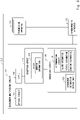
- Fig. 2 is a block diagram showing a specific configuration example of the terminal station apparatus 1_1. In the following descriptions, the management and control of the monitoring results in the terminal station apparatus 1_1 will be described.
- the terminal station apparatus 1_1 has a function of collecting, managing, and controlling the monitoring results of the submarine device 2_1 and 2_2 obtained by the submarine devices 2_1 and 2_2, respectively.
- the terminal station apparatus 1_1 includes a wavelength multiplexing apparatus 111, a transmission apparatus 112 such as SLTE or TPND, and a system monitoring apparatus 113 for monitoring the entire submarine optical communication system SYS1.
- the wavelength multiplexing apparatus 111 may be, for example, a WME (Wavelength Multiplexing Equipment) and may include an optical CouPLer (CPL)) 114, a reception circuit 115, a control and management circuit 116, and an optical circuit 117.
- WME Widelength Multiplexing Equipment
- CPL optical CouPLer
- the optical coupler 114 splits the optical signal supplied through the submarine cable 3. One optical signal split by the optical coupler 114 is supplied to the transmission apparatus 112, and the other one of the split optical signal is received by the reception circuit 115.
- the reception circuit 115 may include, for example, an Optical Channel Monitor (OCM) 118 to monitor optical power (intensity) of each channel of an optical signal.
- OCM Optical Channel Monitor
- the reception circuit 115 extracts the intensities of the optical signals of the channels CH2 and CHk used for transmitting the monitoring results of the submarine devices 2_1 and 2_2 obtained by the submarine devices 2_1 and 2_2, respectively.
- the management circuit 116 includes, for example, a determination circuit 119 and a management information storage unit 120.
- the determination circuit 119 identifies the monitoring results of the submarine devices 2_1 and 2_2 obtained by the submarine devices 2_1 and 2_2, respectively, from the intensities of the optical signals of the channels CH2 and CHk, respectively, extracted by the reception circuit 115. These monitoring results are stored and managed in the management information storage unit 120. Then, predetermined control is performed based on the monitoring results stored in the management information storage unit 120.
- a plurality of submarine devices adjust intensities of optical signals in different wavelength bands included in common optical signals based on respective monitoring results, and output the optical signals including the respective monitoring results.
- the plurality of submarine devices can freely transmit the monitoring results of the respective submarine devices without worrying about each other's transmission state of the monitoring result.
- a plurality of submarine devices can simultaneously transmit the their monitoring results to the terminal station apparatus.
- each of the submarine devices can autonomously transmit the monitoring result to the terminal station apparatus without waiting for a command signal from the terminal station apparatus, for example, when a failure occurs in the submarine device itself.
- the submarine optical communication system SYS1 includes two submarine devices 2_1 and 2_2 has been described as an example, but the present disclosure is not limited thereto.
- the submarine optical communication system SYS1 can be suitably changed to a configuration having three or more submarine devices 2_1 to 2_n (n is an integer of three or more).
- the present disclosure has been described as a hardware configuration, but the present disclosure is not limited thereto.
- the present disclosure can also be implemented by causing a CPU (Central Processing Unit) to execute a computer program for transmitting the monitoring result in the submarine optical communication system SYS1.
- a CPU Central Processing Unit
- Non-transitory computer readable media include any type of tangible storage media.
- Examples of non-transitory computer readable media include magnetic storage media, optical magnetic storage media, CD-ROM (Read Only Memory), CD-R, CD-R/W, and semiconductor memories.
- Examples of magnetic storage media include floppy disks, magnetic tapes, hard disk drives, etc.
- Examples of optical magnetic storage media include magneto-optical disks.
- Examples of semiconductor memories include such as mask ROM, PROM (Programmable ROM), EPROM (Erasable PROM), flash ROM, RAM (Random Access Memory), etc.).
- the program may be provided to a computer using any type of transitory computer readable media. Examples of transitory computer readable media include electric signals, optical signals, and electromagnetic waves. Transitory computer readable media can provide the program to a computer via a wired communication line (e.g. electric wires, and optical fibers) or a wireless communication line.
- a submarine optical communication system comprising:
- the submarine optical communication system according to any one of Supplementary notes 1 to 5, wherein at least one of the plurality of terminal station apparatuses comprises:
- a method of transmitting a monitoring result comprising:
Landscapes
- Engineering & Computer Science (AREA)
- Computer Networks & Wireless Communication (AREA)
- Signal Processing (AREA)
- Physics & Mathematics (AREA)
- Electromagnetism (AREA)
- Optical Communication System (AREA)
Abstract
Description
- The present disclosure relates to a submarine optical communication system and a method of transmitting a monitoring result.
- The submarine optical communication system includes a plurality of terminal station apparatuses provided on land, a submarine cable for transmitting communication between the plurality of terminal station apparatuses, and a submarine device provided at a relay point of the submarine cable. The submarine device transmits, relays, and splits optical signals propagating through the submarine cable.
- In order to improve reliability, the submarine device monitors an operation state of itself, and transmits a result of the monitoring to one of a plurality of the terminal station apparatuses having a function of managing the monitoring results among the plurality of terminal station apparatuses provided on land.
- Techniques related to a submarine optical communication system and a method of transmitting the monitoring results of the submarine device provided in the submarine optical communication system are disclosed in, for example,
Patent Literature - In
Patent Literature - Further, in
Patent Literature 3, the relay apparatus includes optical receiving means for receiving a wavelength-multiplexed optical signal, and processing means for selecting an optical signal in a first wavelength from the wavelength-multiplexed optical signal, performing intensity modulation according to notification information, returning the intensity-modulated optical signal back to the wavelength-multiplexed optical signal, and outputting the wavelength-multiplexed optical signal. In this manner, the relay apparatus can output a monitoring optical signal (a monitoring result of the relay apparatus itself) without having a light source for the monitoring optical signal. -
- Patent Literature 1:
Japanese Unexamined Patent Application Publication No. H09-18410 - Patent Literature 2: International Patent Publication No.
WO2018/003912 - Patent Literature 3: International Patent Publication No.
WO2015/145985 - However, in the related art, when there are a plurality of relay apparatuses (submarine devices) to be monitored, no consideration has been given to a case in which the plurality of relay apparatuses simultaneously transmit the monitoring results to the terminal station apparatus.
- For example, in the configurations of
Patent Literature Patent Literature Patent Literature - Further, in
Patent Literature 3, a relay apparatus is merely configured to be able to adjust a modulation intensity of an optical signal in a designated wavelength for the purpose of outputting a monitoring optical signal (a monitoring result of the relay apparatus) without including a light source for the monitoring optical signal in the relay apparatus. In other words, inPatent Literature 3, no consideration has been given to a case in which a plurality of relay apparatuses simultaneously transmit the monitoring results to the monitoring results. Therefore, in the configuration disclosed inPatent Literature 3, when there are a plurality of relay apparatuses to be monitored, it is necessary for each relay apparatus to transmit the monitoring result of the relay apparatus itself when the monitoring results are not transmitted by the other relay apparatuses so that the transmission of the monitoring result does not collide with the transmission of the monitoring results by the other relay apparatuses. That is, in the configuration ofPatent Literature 3, when there are a plurality of relay apparatuses to be monitored, the plurality of relay apparatuses cannot simultaneously transmit the monitoring results to the terminal station apparatus. - Further, in
Patent Literature 3, since an optically complicated circuit configuration is adopted in which a response signal light wavelength is split and extracted from a reception main signal by using a filter, modulated by VOA, and then multiplexed, there is a possibility that a main signal may be degraded. Additionally, this configuration require a dedicated circuit for light intensity modulation for a response. Further, since the optical wavelength used for the response cannot be changed in each splitter or repeater after the operation is started, a system including many optical branch apparatuses cannot support dynamic optical path changes. An amount of information that can be transmitted from each branch or repeater is also limited to binary information. - In short, in the related art, when there are a plurality of relay apparatuses (submarine devices) to be monitored, there is a problem that the plurality of relay apparatuses cannot freely transmit the monitoring results to the terminal station apparatus without worrying about each other's transmission state of the monitoring result.
- An object of the present disclosure is to provide a submarine optical communication system and a method of transmitting a monitoring result that solve the above problems.
- An example aspect is a submarine optical communication system including: a plurality of terminal station apparatuses; a submarine cable configured to transmit optical signals used for communication between the plurality of terminal station apparatuses; and a first submarine device and a second submarine device provided at relay points of the submarine cable. The first submarine device includes: a first monitoring circuit configured to monitor an operation state of the first submarine device; and a first optical signal adjusting circuit configured to adjust an intensity of an optical signal in a first wavelength band assigned to the first submarine device among the optical signals supplied to the first submarine device based on a first monitoring result obtained by the first monitoring circuit and output the adjusted optical signal as an optical signal including the first monitoring result. The second submarine device includes: a second monitoring circuit configured to monitor an operation state of the second submarine device; and a second optical signal adjusting circuit configured to adjust an intensity of an optical signal in a second wavelength band assigned to the second submarine device among the optical signals supplied to the second submarine device based on a second monitoring result obtained by the second monitoring circuit and output the adjusted optical signal as an optical signal including the second monitoring result, the second wavelength band being different from the first wavelength band assigned to the first submarine device.
- In another example aspect, a method of transmitting a monitoring result including: a first monitoring step of monitoring, in a first submarine device, an operation state of the first submarine device; a second monitoring step of monitoring, in a second submarine device, an operation state of the second submarine device; a first optical signal adjusting step of adjusting, in the first submarine device, an intensity of an optical signal in a first wavelength band assigned to the first submarine device among optical signals supplied to the first submarine device based on a first monitoring result obtained in the first monitoring step and outputting the adjusted optical signal as an optical signal including the first monitoring result; and a second optical signal adjusting step of adjusting, in the second submarine device, an intensity of an optical signal in a second wavelength band assigned to the second submarine device among the optical signals supplied to the second submarine device based on a second monitoring result obtained in the second monitoring step and outputting the adjusted optical signal as an optical signal including the second monitoring result, the second wavelength band being different from the first wavelength band assigned to the first submarine device.
- According to the above example aspects, it is possible to provide a submarine optical communication system in which each of a plurality of submarine devices can freely transmit a monitoring result of the submarine device itself without worrying about each other's transmission state of a monitoring result, and a method of transmitting the monitoring result.
-
-
Fig. 1 is a block diagram schematically showing a submarine optical communication system according to a first example embodiment; -
Fig. 2 is a block diagram showing a specific configuration example of a submarine device provided in the submarine optical communication system shown inFig. 1 ; -
Fig. 3 is a diagram for explaining an optical signal before transmission of a monitoring result of the submarine device obtained by the submarine device provided in the submarine optical communication system shown inFig. 1 ; -
Fig. 4 is a diagram for explaining a first method of transmitting a monitoring result of the submarine device obtained by the submarine device itself provided in the submarine optical communication system shown inFig. 1 ; -
Fig. 5 is a diagram for explaining a second method of transmitting a monitoring result of the submarine device obtained by the submarine device itself provided in the submarine optical communication system shown inFig. 1 ; -
Fig. 6 is a diagram for explaining a third method of transmitting a monitoring result of the submarine device obtained by the submarine device itself provided in the submarine optical communication system shown inFig. 1 ; -
Fig. 7 is a diagram for explaining a fourth method of transmitting a monitoring result of the submarine device obtained by the submarine device itself provided in the submarine optical communication system shown inFig. 1 ; and -
Fig. 8 is a block diagram showing a specific configuration example of a terminal station apparatus provided in the submarine optical communication system shown inFig. 1 . - An example embodiment will be described below with reference to the drawings. Since the drawings are simple, the technical scope of the example embodiment should not be narrowly interpreted based on the description of the drawings. The same elements are denoted by the same reference signs, and repeated descriptions are omitted.
- The disclosure will be described by dividing it into a plurality of sections or example embodiment whenever circumstances require it for convenience in the following embodiment.
- However, unless otherwise particularly specified, these sections or embodiment are not irrelevant to one another. One section or example embodiment is related to modified example, applications, details, supplementary explanations, and the like of some or all of the other ones. When reference is made to the number of elements or the like (including the number of pieces, numerical values, quantity, range, etc.) in the following example embodiment, the number thereof is not limited to a specific number and may be greater than or less than or equal to the specific number unless otherwise particularly specified and definitely limited to the specific number in principle.
- Further, in the following example embodiment, components (including operation steps, etc.) are not always essential unless otherwise particularly specified and considered to be definitely essential in principle. Similarly, when reference is made to the shapes, positional relations, or the like of the components or the like in the following example embodiment, they will include ones, for example, substantially approximate or similar in their shapes or the like unless otherwise particularly specified and considered not to be definitely so in principle. This is similarly applied even to the above-described number or the like (including the number of pieces, numerical values, quantity, range, etc.).
-
Fig. 1 is a block diagram schematically showing a submarine optical communication system SYS1 according to a first example embodiment. As shown inFig. 1 , the submarine optical communication system SYS1 includes a plurality (four in the example ofFig. 1 ) ofterminal station apparatuses 1, a plurality (two in the example ofFig. 1 ) ofsubmarine devices 2, andsubmarine cables 3. In the example ofFig. 1 , in order to distinguish the four terminal station apparatuses, theterminal station apparatuses 1 are referred to as terminal station apparatuses 1_1 to 1_4, respectively. Further, in order to distinguish the twosubmarine devices 2, thesubmarine devices 2 are referred to as submarine devices 2_1 and 2_2, respectively. - The terminal station apparatuses 1_1 to 1_4 are provided on land and are configured to communicate with each other through the
submarine cables 3. At least one of the terminal station apparatuses 1_1 to 1_4 has a function of collecting results of monitoring the submarine devices 2_1 and 2_2 performed by the submarine devices 2_1 and 2_2, respectively, and managing and controlling the monitoring results. - Each of the
submarine cables 3 transmits optical signals used for communication between the terminal station apparatuses 1_1 to 1_4. Each of the submarine devices 2_1 and 2_2 is provided at a relay point (on the bottom of the sea) of thesubmarine cable 3, and transmits, relays, and splits the optical signals propagating through thesubmarine cable 3. - A
monitoring circuit 211 monitors an operation state of the submarine device 2_1. Specifically, the submarine device 2_1 includes at least themonitoring circuit 211 and an opticalsignal adjusting circuit 212. The opticalsignal adjusting circuit 212 adjusts an intensity of the optical signal in a wavelength band (a first wavelength band) assigned to the submarine device 2_1 among the optical signals (wavelength multiplexed optical signals) supplied to the submarine device 2_1 through thesubmarine cable 3, based on the monitoring result obtained by themonitoring circuit 211. Then, the opticalsignal adjusting circuit 212 outputs the adjusted optical signal as an optical signal including the monitoring result obtained by themonitoring circuit 211. This optical signal including the monitoring result obtained by themonitoring circuit 211 is transmitted through thesubmarine cable 3 to the terminal station apparatus (e.g., the terminal station apparatus 1_1) for managing and controlling the monitoring result of the submarine device 2_1. - Similarly, a
monitoring circuit 221 monitors an operation state of the submarine device 2_2. Specifically, the submarine device 2_2 includes at least themonitoring circuit 221 and an opticalsignal adjusting circuit 222. The opticalsignal adjusting circuit 222 adjusts an intensity of the optical signal in a wavelength band (a second wavelength band) assigned to the submarine device 2_2 among the optical signals (wavelength multiplexed optical signals) supplied to the submarine device 2_2 through thesubmarine cable 3, based on the monitoring result obtained by themonitoring circuit 221. Note that the wavelength band of the optical signal assigned to the submarine device 2_2 is different from the wavelength band of the optical signal assigned to the submarine device 2_1. Then, the opticalsignal adjusting circuit 222 outputs the adjusted optical signal as an optical signal including the monitoring result obtained by themonitoring circuit 221. This optical signal including the monitoring result obtained by themonitoring circuit 221 is transmitted through thesubmarine cable 3 to the terminal station apparatus (e.g., the terminal station apparatus 1_1) for managing and controlling the monitoring results of the submarine device 2_2. - As described above, in the submarine optical communication system SYS1 according to this example embodiment, a plurality of submarine devices adjust the intensities of the optical signals in different wavelength bands included in common optical signals based on each of the monitoring results, and output the optical signals including the monitoring results, respectively. Thus, in the submarine optical communication system SYS1 according to this example embodiment, each of the plurality of submarine devices can freely transmit the monitoring result of the submarine device itself without worrying about each other's transmission state of the monitoring result. It is thus possible, for example, for the plurality of submarine devices to simultaneously transmit the respective monitoring results to the terminal station apparatus. Further, for example, when a failure occurs in any of the submarine devices, each of the submarine devices can autonomously transmit the monitoring result to the terminal station apparatus without waiting for a command signal from the terminal station apparatus. Furthermore, in this configuration, the configuration and assignment of the light wavelength and the like used for a response can be changed after the operation is started.
- Next, the details of the submarine device 2_1 and the terminal station apparatus 1_1 will be described. Note that the submarine device 2_2 has basically the same configuration as that of the submarine device 2_1 except that the wavelength band assigned to the submarine device 2_2 for transmitting the monitoring result is different from that assigned to the submarine device 2_1. Therefore, the description of the submarine device 2_2 will be omitted. The terminal station apparatuses 1_2 to 1_4 have basically the same configuration as that of the terminal station apparatus 1_1, and therefore, a description thereof will be omitted.
- «Specific example of submarine device 2_1»
-
Fig. 2 is a block diagram showing a specific configuration example of the submarine device 2_1. - As shown in
Fig. 2 , the submarine device 2_1 includes themonitoring circuit 211, the opticalsignal adjusting circuit 212, andoptical circuits 215 to 217. The opticalsignal adjusting circuit 212 is composed of aspectrum control circuit 213 and an outputlight control circuit 214. - The output
light control circuit 214 has a function as a Wavelength Selectable Switch (WSS) for selecting one of a plurality of optical signals supplied from the plurality ofsubmarine cables 3 of different paths and outputting the selected optical signal. The outputlight control circuit 214 adjusts the intensity of the optical signal supplied through thesubmarine cable 3. - As described above, the
monitoring circuit 211 monitors the operation state of the submarine device 2_1. The operation state of the submarine device 2_1 includes status information, alarm information, monitor information, and the like of the submarine device 2_1. - The
spectrum control circuit 213 controls a spectrum (a wavelength intensity) of the optical signal output from the outputlight control circuit 214 based on the monitoring result obtained by themonitoring circuit 211. Thus, the outputlight control circuit 214 adjusts the intensity of the optical signal in the wavelength band assigned to the submarine device 2_1 among the optical signals to the intensity according to the monitoring result obtained by themonitoring circuit 211. An amount of adjustment of the intensity of the optical signal is controlled to such an extent that it does not affect communication quality. However, when there is a possibility that the communication quality deteriorates due to a slight change in the intensity of the optical signal in a predetermined wavelength band, the predetermined wavelength band is excluded from the wavelength band used for transmitting the monitoring result. -
Fig. 3 is a diagram for explaining the optical signal before the monitoring result of the submarine device 2_1 is transmitted by the submarine device 2_1. Referring toFig. 3 , the optical signal propagating through thesubmarine cable 3 is, for example, a wavelength multiplexed optical signal composed of optical signals of a plurality of channels CH1 to CHk (k is an integer of two or more). -
Fig. 4 is a diagram for explaining a first method of transmitting the monitoring result of the submarine device 2_1 by the submarine device 2_1. Referring toFig. 4 , the outputlight control circuit 214 adjusts the intensity of the optical signal of the channel CH2 assigned to the submarine device 2_1 among the optical signals based on the monitoring result obtained by themonitoring circuit 211. For example, when there is an abnormality in the submarine device 2_1, the outputlight control circuit 214 makes the intensity of the optical signal of the channel CH2 weaker than a reference intensity, while when there is no abnormality in the submarine device 2_1, the outputlight control circuit 214 makes the intensity of the optical signal of the channel CH2 stronger than the reference intensity. - In the example of
Fig. 4 , the channel CHk is assigned to the submarine device 2_2 as a channel for transmitting the monitoring result. Therefore, the submarine device 2_2 adjusts the intensity of the optical signal of the channel CHk based on the monitoring result obtained by themonitoring circuit 221. - In this way, the submarine devices 2_1 and 2_2 adjust the intensities of the optical signals in different wavelength bands included in the common optical signals based on the respective monitoring results. Thus, in the submarine optical communication system SYS1, each of the submarine devices 2_1 and 2_2 can freely transmit the monitoring result of the submarine devices 2_1 and 2_2, respectively, without worrying about each other's transmission state of the monitoring result.
- Note that how the intensity of the optical signal is controlled according to the monitoring result can be configured in any way. For example, when there is no abnormality in the submarine device 2_1, the intensity of the optical signal of the channel CH2 may be maintained at the reference intensity instead of making it stronger than the reference intensity. Alternatively, the intensity of the optical signal of the channel CH2 may be controlled only when a specific abnormality (a failure at a specific location) in the submarine device 2_1 occurs.
-
Fig. 5 is a diagram for explaining a second method of transmitting the monitoring result of the submarine device 2_1 obtained by the submarine device 2_1. Referring toFig. 5 , the outputlight control circuit 214 adjusts an amount of change of the optical signal of the channel CH2 from the reference intensity based on the monitoring result obtained by themonitoring circuit 211. For example, the outputlight control circuit 214 adjusts the amount of change of the optical signal of the channel CH2 from the reference intensity based on the status information, the alarm information, and the monitor information of the submarine device 2_1. By doing so, the submarine device 2_1 can collectively transmit a plurality of pieces of information included in the monitoring result obtained by themonitoring circuit 211. - In the example of
Fig. 5 , the channel CHk is assigned to the submarine device 2_2 as a channel for transmitting the monitoring result. Therefore, the submarine device 2_2 adjusts the amount of change of the optical signal of the channel CHk from the reference intensity based on the monitoring result obtained by themonitoring circuit 221. Thus, the submarine device 2_2 can collectively transmit a plurality of pieces of information included in the monitoring result obtained by themonitoring circuit 221. - In the example shown in
Fig. 5 , the submarine devices 2_1 and 2_2 adjust the amount of change of the optical signals of the channels CH2 and CHk from the reference intensity based on the monitoring results obtained by the submarine devices 2_1 and 2_2, respectively, but the present disclosure is not limited to this. For example, the submarine devices 2_1 and 2_2 may adjust a period in which the intensities of the optical signals in the wavelength bands of the channels CH2 and CHk are changed based on the monitoring results obtained by the submarine devices 2_1 and 2_2, respectively. In other words, the submarine devices 2_1 and 2_2 may be capable of transmitting notifications about different monitoring results including an alarm or the like depending on a difference in a period of time during which the intensity of the optical signal is changed. For example, if the period of time during which the intensity of the optical signal is changed is 1 second, a first alarm A is indicated, while if the period of time during which the intensity of the optical signal is changed is 2 seconds, a second alarm B is indicated. -
Fig. 6 is a diagram for explaining a third method of transmitting the monitoring result of the submarine device 2_1 obtained by the submarine device 2_1. Referring toFig. 6 , the channel CH2 assigned to the submarine device 2_1 is composed of a plurality of channels CH2_1 to CH2_3. Here, the outputlight control circuit 214 adjusts the intensities of the respective optical signals of the channels CH2_1 to CH2_3 based on the monitoring result obtained by themonitoring circuit 211. For example, the outputlight control circuit 214 adjusts the intensity of the respective optical signals of the channels CH2_1 to CH2_3 based on the status information, the alarm information, and the monitor information of the submarine device 2_1. Thus, the submarine device 2_1 can collectively transmit a plurality of pieces of information included in the monitoring result obtained by themonitoring circuit 211. - In the example of
Fig. 6 , the channel CHk assigned to the submarine device 2_2 is composed of a plurality of channels CHk_1 to CHk_3. Therefore, the submarine device 2_2 adjusts the intensities of the respective optical signals of the channels CHk_1 to CHk_3 based on, for example, the status information, the alarm information, and the monitor information of the submarine device 2_2. Thus, the submarine device 2_2 can collectively transmit a plurality of pieces of information included in the monitoring result obtained by themonitoring circuit 221. -
Fig. 7 is a diagram for explaining a fourth method of transmitting the monitoring result of the submarine device 2_1 obtained by the submarine device 2_1. Referring toFig. 7 , the outputlight control circuit 214 blocks the output of the optical signal of the channel CH2 (i.e., the intensity is made substantially zero), because there is, for example, an abnormality in the submarine device 2_1. In this case, in response to receiving the optical signal, the terminal station apparatus 1_1 causes a transmission apparatus such as SLTE or TPND to generate an LOS (Loss Of Signal) alarm and an LOF (Loss Of Frame) alarm, thereby determining that there is an abnormality in the submarine device 2_1. SLTE stands for Submarine Line Terminal Equipment. TPND stands for TransPoNDer. - In addition, in the example of
Fig. 7 , the submarine device 2_2 blocks the output of the optical signal of the channel CHk, for example, when there is an abnormality in the submarine device 2_2. In the example ofFig. 7 , since no abnormality has occurred in the submarine device 2_2, the output of the optical signal of the channel CHk is not blocked. - In the example of
Fig. 7 , the submarine devices 2_1 and 2_2 block the output of the optical signals of the channels CH2 and CHk when there is an abnormality in the submarine devices 2_1 and 2_2, respectively, but the present disclosure is not limited to this. The submarine devices 2_1 and 2_2 may block the output of the optical signals of the channels CH2 and CHk when it is necessary to transmit a notification about a specific monitoring result, for example, when an urgent situation occurs. In this case, in response to receiving the optical signal, the terminal station apparatus 1_1 causes the transmission apparatus such as SLTE or TPND to generate an alarm of signal degradation, thereby determining that there is an abnormality in the submarine devices 2_1 and 2_2. - Further, in the example of
Fig. 7 , the submarine devices 2_1 and 2_2 block the output of the optical signals of the channels CH2 and CHk when there is an abnormality in the submarine devices 2_1 and 2_2, respectively, but the present disclosure is not limited to this. For example, the submarine devices 2_1 and 2_2 may operate levels of the optical signals of the channels CH2 and CHk to deteriorate the communication quality when there is an abnormality in the submarine devices 2_1 and 2_2, respectively. In this case, in response to receiving the optical signal, the terminal station apparatus 1_1 causes the transmission apparatus such as SLTE or TPND to generate an alarm of signal degradation, thereby determining that there is an abnormality in the submarine devices 2_1 and 2_2. - The first to fourth methods of transmitting the monitoring results by the submarine device 2_1 (and 2_2) may be used in combination.
-
Fig. 2 is a block diagram showing a specific configuration example of the terminal station apparatus 1_1. In the following descriptions, the management and control of the monitoring results in the terminal station apparatus 1_1 will be described. - As shown in
Fig. 2 , the terminal station apparatus 1_1 has a function of collecting, managing, and controlling the monitoring results of the submarine device 2_1 and 2_2 obtained by the submarine devices 2_1 and 2_2, respectively. Specifically, the terminal station apparatus 1_1 includes awavelength multiplexing apparatus 111, atransmission apparatus 112 such as SLTE or TPND, and asystem monitoring apparatus 113 for monitoring the entire submarine optical communication system SYS1. - The
wavelength multiplexing apparatus 111 may be, for example, a WME (Wavelength Multiplexing Equipment) and may include an optical CouPLer (CPL)) 114, areception circuit 115, a control andmanagement circuit 116, and anoptical circuit 117. - The
optical coupler 114 splits the optical signal supplied through thesubmarine cable 3. One optical signal split by theoptical coupler 114 is supplied to thetransmission apparatus 112, and the other one of the split optical signal is received by thereception circuit 115. - The
reception circuit 115 may include, for example, an Optical Channel Monitor (OCM) 118 to monitor optical power (intensity) of each channel of an optical signal. In other words, thereception circuit 115 extracts the intensities of the optical signals of the channels CH2 and CHk used for transmitting the monitoring results of the submarine devices 2_1 and 2_2 obtained by the submarine devices 2_1 and 2_2, respectively. - The
management circuit 116 includes, for example, adetermination circuit 119 and a management information storage unit 120. Thedetermination circuit 119 identifies the monitoring results of the submarine devices 2_1 and 2_2 obtained by the submarine devices 2_1 and 2_2, respectively, from the intensities of the optical signals of the channels CH2 and CHk, respectively, extracted by thereception circuit 115. These monitoring results are stored and managed in the management information storage unit 120. Then, predetermined control is performed based on the monitoring results stored in the management information storage unit 120. - As described above, in the submarine optical communication system SYS1 according to this example embodiment, a plurality of submarine devices adjust intensities of optical signals in different wavelength bands included in common optical signals based on respective monitoring results, and output the optical signals including the respective monitoring results. Thus, in the submarine optical communication system SYS1 according to this example embodiment, the plurality of submarine devices can freely transmit the monitoring results of the respective submarine devices without worrying about each other's transmission state of the monitoring result. Thus, for example, a plurality of submarine devices can simultaneously transmit the their monitoring results to the terminal station apparatus. Furthermore, each of the submarine devices can autonomously transmit the monitoring result to the terminal station apparatus without waiting for a command signal from the terminal station apparatus, for example, when a failure occurs in the submarine device itself.
- In the above example embodiment, the case where the submarine optical communication system SYS1 includes two submarine devices 2_1 and 2_2 has been described as an example, but the present disclosure is not limited thereto. The submarine optical communication system SYS1 can be suitably changed to a configuration having three or more submarine devices 2_1 to 2_n (n is an integer of three or more).
- Although the example embodiment of the present disclosure has been described in detail with reference to the drawings, the specific configuration is not limited to the above, and various design changes and the like are possible within the scope not departing from the gist of the present disclosure.
- In the above-described example embodiment, the present disclosure has been described as a hardware configuration, but the present disclosure is not limited thereto. The present disclosure can also be implemented by causing a CPU (Central Processing Unit) to execute a computer program for transmitting the monitoring result in the submarine optical communication system SYS1.
- The program can be stored and provided to a computer using any type of non-transitory computer readable media. Non-transitory computer readable media include any type of tangible storage media. Examples of non-transitory computer readable media include magnetic storage media, optical magnetic storage media, CD-ROM (Read Only Memory), CD-R, CD-R/W, and semiconductor memories. Examples of magnetic storage media include floppy disks, magnetic tapes, hard disk drives, etc. Examples of optical magnetic storage media include magneto-optical disks. Examples of semiconductor memories include such as mask ROM, PROM (Programmable ROM), EPROM (Erasable PROM), flash ROM, RAM (Random Access Memory), etc.). The program may be provided to a computer using any type of transitory computer readable media. Examples of transitory computer readable media include electric signals, optical signals, and electromagnetic waves. Transitory computer readable media can provide the program to a computer via a wired communication line (e.g. electric wires, and optical fibers) or a wireless communication line.
- The whole or part of the exemplary embodiment disclosed above can be described as, but not limited to, the following supplementary notes.
- A submarine optical communication system comprising:
- a plurality of terminal station apparatuses;
- a submarine cable configured to transmit optical signals used for communication between the plurality of terminal station apparatuses; and
- a first submarine device and a second submarine device provided at relay points of the submarine cable, wherein
- the first submarine device comprises:
- a first monitoring circuit configured to monitor an operation state of the first submarine device; and
- a first optical signal adjusting circuit configured to adjust an intensity of an optical signal in a first wavelength band assigned to the first submarine device among the optical signals supplied to the first submarine device based on a first monitoring result obtained by the first monitoring circuit and output the adjusted optical signal as an optical signal including the first monitoring result,
- the second submarine device comprises:
- a second monitoring circuit configured to monitor an operation state of the second submarine device; and
- a second optical signal adjusting circuit configured to adjust an intensity of an optical signal in a second wavelength band assigned to the second submarine device among the optical signals supplied to the second submarine device based on a second monitoring result obtained by the second monitoring circuit and output the adjusted optical signal as an optical signal including the second monitoring result, the second wavelength band being different from the first wavelength band assigned to the first submarine device.
- The submarine optical communication system according to
Supplementary note 1, wherein - the first optical signal adjusting circuit is configured to adjust an amount of change of the optical signal in the first wavelength band from a reference intensity based on the first monitoring result obtained by the first monitoring circuit, and
- the second optical signal adjusting circuit is configured to adjust an amount of change of the optical signal in the second wavelength band from a reference intensity based on the second monitoring result obtained by the second monitoring circuit.
- The submarine optical communication system according to
Supplementary note - the first wavelength band is composed of a plurality of first partial wavelength bands,
- the second wavelength band is composed of a plurality of second partial wavelength bands,
- the first optical signal adjusting circuit is configured to adjust the intensities of the optical signals in the plurality of first partial wavelength bands based on the first monitoring result obtained by the first monitoring circuit, and
- the second optical signal adjusting circuit is configured to adjust the intensities of the optical signals in the plurality of second partial wavelength bands based on the second monitoring result obtained by the second monitoring circuit.
- The submarine optical communication system according to any one of
Supplementary notes 1 to 3, wherein - the first optical signal adjusting circuit is configured to block an output of the optical signal in the first wavelength band assigned to the first submarine device based on the first monitoring result showing a specific monitoring result, and
- the second optical signal adjusting circuit is configured to block the output of the optical signal in the second wavelength band assigned to the second submarine device based on the second monitoring result indicating a specific monitoring result.
- The submarine optical communication system according to any one of
Supplementary notes 1 to 4, wherein - the first optical signal adjusting circuit is configured to exclude a predetermined frequency band from a target of the first wavelength band assigned to the first submarine device, and
- the second optical signal adjusting circuit is configured to exclude a predetermined frequency band from a target of the second wavelength band assigned to the second submarine device.
- The submarine optical communication system according to any one of
Supplementary notes 1 to 5, wherein
at least one of the plurality of terminal station apparatuses comprises: - a monitoring result acquisition circuit configured to acquire the first monitoring result from the intensity of the optical signal in the first wavelength band and extract the second monitoring result from the intensity of the optical signal in the second wavelength band; and
- a management circuit configured to manage the monitoring results extracted by the monitoring result acquisition circuit.
- A method of transmitting a monitoring result comprising:
- a first monitoring step of monitoring, in a first submarine device, an operation state of the first submarine device;
- a second monitoring step of monitoring, in a second submarine device, an operation state of the second submarine device;
- a first optical signal adjusting step of adjusting, in the first submarine device, an intensity of an optical signal in a first wavelength band assigned to the first submarine device among optical signals supplied to the first submarine device based on a first monitoring result obtained in the first monitoring step and outputting the adjusted optical signal as an optical signal including the first monitoring result; and
- a second optical signal adjusting step of adjusting, in the second submarine device, an intensity of an optical signal in a second wavelength band assigned to the second submarine device among the optical signals supplied to the second submarine device based on a second monitoring result obtained in the second monitoring step and outputting the adjusted optical signal as an optical signal including the second monitoring result, the second wavelength band being different from the first wavelength band assigned to the first submarine device.
- The method according to Supplementary note 7, wherein
- in the first optical signal adjusting step, in the first submarine device, an amount of change of the optical signal in the first wavelength band from a reference intensity is adjusted based on the first monitoring result, and
- in the second optical signal adjusting step, in the second first submarine device, an amount of change of the optical signal in the second wavelength band from a reference intensity is adjusted based on the second monitoring result.
- The method according to Supplementary note 7 or 8, wherein
- the first wavelength band is composed of a plurality of first partial wavelength bands,
- the second wavelength band is composed of a plurality of second partial wavelength bands,
- in the first optical signal adjusting step, in the first submarine device, the intensities of the optical signals in the plurality of first partial wavelength bands are adjusted based on the first monitoring result obtained by the first monitoring circuit, and
- in the second optical signal adjusting step, in the second submarine device, the intensities of the optical signals in the plurality of second partial wavelength bands are adjusted based on the second monitoring result obtained by the second monitoring circuit.
- The method according to any one of Supplementary notes 7 to 9, wherein
- in the first optical signal adjusting step, in the first submarine device, an output of the optical signal in the first wavelength band assigned to the first submarine device is blocked based on the first monitoring result showing a specific monitoring result, and
- in the second optical signal adjusting step, in the second submarine device, an output of the optical signal in the second wavelength band assigned to the second submarine device is blocked based on the second monitoring result showing a specific monitoring result.
- The method according to any one of Supplementary notes 7 to 10, wherein
- in the first optical signal adjusting step, in the first submarine device, a predetermined frequency band is excluded from a target of the first wavelength band assigned to the first submarine device, and
- in the second optical signal adjusting step, in the second submarine device, a predetermined frequency band is excluded from a target of the second wavelength band assigned to the second submarine device.
- The method according to any one of Supplementary notes 7 to 11, wherein
the first submarine device and the second submarine device are both provided at relay points of a submarine cable. - A program for causing a computer to execute:
- a first monitoring process of monitoring, in a first submarine device, an operation state of the first submarine device;
- a second monitoring process of monitoring, in a second submarine device, an operation state of the second submarine device;
- a first optical signal adjusting process of adjusting, in the first submarine device, an intensity of an optical signal in a first wavelength band assigned to the first submarine device among optical signals supplied to the first submarine device based on a first monitoring result obtained in the first monitoring process and outputting the adjusted optical signal as an optical signal including the first monitoring result; and
- a second optical signal adjusting process of adjusting, in the second submarine device, an intensity of an optical signal in a second wavelength band assigned to the second submarine device among the optical signals supplied to the second submarine device based on a second monitoring result obtained in the second monitoring process and outputting the adjusted optical signal as an optical signal including the second monitoring result, the second wavelength band being different from the first wavelength band assigned to the first submarine device.
- Although the present disclosure has been described with reference to the above example embodiment, the present disclosure is not limited thereto. Various changes can be made to the configuration and details of the disclosure within the scope of the disclosure that can be understood by those skilled in the art.
- This application is based upon and claims the benefit of priority from
Japanese patent application No. 2019-164280, filed on September 10, 2019 -
- SYS1
- SUBMARINE OPTICAL COMMUNICATION SYSTEM
- 1, 1_1 TO 1_4
- TERMINAL STATION APPARATUS
- 2, 2_1, 2_2
- SUBMARINE DEVICE
- 3
- SUBMARINE CABLE
- 211
- MONITORING CIRCUIT
- 212
- OPTICAL SIGNAL ADJUSTING CIRCUIT
- 213
- SPECTRUM CONTROL CIRCUIT
- 214
- OUTPUT LIGHT CONTROL CIRCUIT
- 215 TO 217
- OPTICAL CIRCUIT
- 221
- MONITORING CIRCUIT
- 222
- OPTICAL SIGNAL ADJUSTING CIRCUIT
- 111
- WAVELENGTH MULTIPLEXING CIRCUIT
- 112
- TRANSMISSION APPARATUS
- 113
- SYSTEM MONITORING CIRCUIT
- 114
- OPTICAL COUPLER
- 115
- RECEPTION CIRCUIT
- 116
- MANAGEMENT CIRCUIT
- 117
- OPTICAL CIRCUIT
- 118
- OPTICAL CHANNEL MONITOR
- 119
- DETERMINATION CIRCUIT
- 120
- MANAGEMENT INFORMATION STORAGE UNIT
Claims (13)
- A submarine optical communication system comprising:a plurality of terminal station apparatuses;a submarine cable configured to transmit optical signals used for communication between the plurality of terminal station apparatuses; anda first submarine device and a second submarine device provided at relay points of the submarine cable, whereinthe first submarine device comprises:a first monitoring circuit configured to monitor an operation state of the first submarine device; anda first optical signal adjusting circuit configured to adjust an intensity of an optical signal in a first wavelength band assigned to the first submarine device among the optical signals supplied to the first submarine device based on a first monitoring result obtained by the first monitoring circuit and output the adjusted optical signal as an optical signal including the first monitoring result,the second submarine device comprises:a second monitoring circuit configured to monitor an operation state of the second submarine device; anda second optical signal adjusting circuit configured to adjust an intensity of an optical signal in a second wavelength band assigned to the second submarine device among the optical signals supplied to the second submarine device based on a second monitoring result obtained by the second monitoring circuit and output the adjusted optical signal as an optical signal including the second monitoring result, the second wavelength band being different from the first wavelength band assigned to the first submarine device.
- The submarine optical communication system according to Claim 1, whereinthe first optical signal adjusting circuit is configured to adjust an amount of change of the optical signal in the first wavelength band from a reference intensity based on the first monitoring result obtained by the first monitoring circuit, andthe second optical signal adjusting circuit is configured to adjust an amount of change of the optical signal in the second wavelength band from a reference intensity based on the second monitoring result obtained by the second monitoring circuit.
- The submarine optical communication system according to Claim 1 or 2, whereinthe first wavelength band is composed of a plurality of first partial wavelength bands,the second wavelength band is composed of a plurality of second partial wavelength bands,the first optical signal adjusting circuit is configured to adjust the intensities of the optical signals in the plurality of first partial wavelength bands based on the first monitoring result obtained by the first monitoring circuit, andthe second optical signal adjusting circuit is configured to adjust the intensities of the optical signals in the plurality of second partial wavelength bands based on the second monitoring result obtained by the second monitoring circuit.
- The submarine optical communication system according to any one of Claims 1 to 3, whereinthe first optical signal adjusting circuit is configured to block an output of the optical signal in the first wavelength band assigned to the first submarine device based on the first monitoring result showing a specific monitoring result, andthe second optical signal adjusting circuit is configured to block the output of the optical signal in the second wavelength band assigned to the second submarine device based on the second monitoring result indicating a specific monitoring result.
- The submarine optical communication system according to any one of Claims 1 to 4, whereinthe first optical signal adjusting circuit is configured to exclude a predetermined frequency band from a target of the first wavelength band assigned to the first submarine device, andthe second optical signal adjusting circuit is configured to exclude a predetermined frequency band from a target of the second wavelength band assigned to the second submarine device.
- The submarine optical communication system according to any one of Claims 1 to 5, wherein
at least one of the plurality of terminal station apparatuses comprises:a monitoring result acquisition circuit configured to acquire the first monitoring result from the intensity of the optical signal in the first wavelength band and extract the second monitoring result from the intensity of the optical signal in the second wavelength band; anda management circuit configured to manage the monitoring results extracted by the monitoring result acquisition circuit. - A method of transmitting a monitoring result comprising:a first monitoring step of monitoring, in a first submarine device, an operation state of the first submarine device;a second monitoring step of monitoring, in a second submarine device, an operation state of the second submarine device;a first optical signal adjusting step of adjusting, in the first submarine device, an intensity of an optical signal in a first wavelength band assigned to the first submarine device among optical signals supplied to the first submarine device based on a first monitoring result obtained in the first monitoring step and outputting the adjusted optical signal as an optical signal including the first monitoring result; anda second optical signal adjusting step of adjusting, in the second submarine device, an intensity of an optical signal in a second wavelength band assigned to the second submarine device among the optical signals supplied to the second submarine device based on a second monitoring result obtained in the second monitoring step and outputting the adjusted optical signal as an optical signal including the second monitoring result, the second wavelength band being different from the first wavelength band assigned to the first submarine device.
- The method according to Claim 7, whereinin the first optical signal adjusting step, in the first submarine device, an amount of change of the optical signal in the first wavelength band from a reference intensity is adjusted based on the first monitoring result, andin the second optical signal adjusting step, in the second first submarine device, an amount of change of the optical signal in the second wavelength band from a reference intensity is adjusted based on the second monitoring result.
- The method according to Claim 7 or 8, whereinthe first wavelength band is composed of a plurality of first partial wavelength bands,the second wavelength band is composed of a plurality of second partial wavelength bands,in the first optical signal adjusting step, in the first submarine device, the intensities of the optical signals in the plurality of first partial wavelength bands are adjusted based on the first monitoring result obtained by the first monitoring circuit, andin the second optical signal adjusting step, in the second submarine device, the intensities of the optical signals in the plurality of second partial wavelength bands are adjusted based on the second monitoring result obtained by the second monitoring circuit.
- The method according to any one of Claims 7 to 9, whereinin the first optical signal adjusting step, in the first submarine device, an output of the optical signal in the first wavelength band assigned to the first submarine device is blocked based on the first monitoring result showing a specific monitoring result, andin the second optical signal adjusting step, in the second submarine device, an output of the optical signal in the second wavelength band assigned to the second submarine device is blocked based on the second monitoring result showing a specific monitoring result.
- The method according to any one of Claims 7 to 10, whereinin the first optical signal adjusting step, in the first submarine device, a predetermined frequency band is excluded from a target of the first wavelength band assigned to the first submarine device, andin the second optical signal adjusting step, in the second submarine device, a predetermined frequency band is excluded from a target of the second wavelength band assigned to the second submarine device.
- The method according to any one of Claims 7 to 11, wherein
the first submarine device and the second submarine device are both provided at relay points of a submarine cable. - A non-transitory computer readable medium storing a program for causing a computer to execute:a first monitoring process of monitoring, in a first submarine device, an operation state of the first submarine device;a second monitoring process of monitoring, in a second submarine device, an operation state of the second submarine device;a first optical signal adjusting process of adjusting, in the first submarine device, an intensity of an optical signal in a first wavelength band assigned to the first submarine device among optical signals supplied to the first submarine device based on a first monitoring result obtained in the first monitoring process and outputting the adjusted optical signal as an optical signal including the first monitoring result; anda second optical signal adjusting process of adjusting, in the second submarine device, an intensity of an optical signal in a second wavelength band assigned to the second submarine device among the optical signals supplied to the second submarine device based on a second monitoring result obtained in the second monitoring process and outputting the adjusted optical signal as an optical signal including the second monitoring result, the second wavelength band being different from the first wavelength band assigned to the first submarine device.
Applications Claiming Priority (2)
| Application Number | Priority Date | Filing Date | Title |
|---|---|---|---|
| JP2019164280 | 2019-09-10 | ||
| PCT/JP2020/019217 WO2021049099A1 (en) | 2019-09-10 | 2020-05-14 | Optical submarine communication system, monitoring result conveyance method, and non-transitory computer-readable medium in which program is stored |
Publications (1)
| Publication Number | Publication Date |
|---|---|
| EP4030638A1 true EP4030638A1 (en) | 2022-07-20 |
Family
ID=74866920
Family Applications (1)
| Application Number | Title | Priority Date | Filing Date |
|---|---|---|---|
| EP20863156.4A Withdrawn EP4030638A1 (en) | 2019-09-10 | 2020-05-14 | Optical submarine communication system, monitoring result conveyance method, and non-transitory computer-readable medium in which program is stored |
Country Status (5)
| Country | Link |
|---|---|
| US (1) | US11843415B2 (en) |
| EP (1) | EP4030638A1 (en) |
| JP (1) | JP7359214B2 (en) |
| CN (1) | CN114375549B (en) |
| WO (1) | WO2021049099A1 (en) |
Families Citing this family (3)
| Publication number | Priority date | Publication date | Assignee | Title |
|---|---|---|---|---|
| US12334994B2 (en) | 2021-09-22 | 2025-06-17 | Nec Corporation | Control apparatus, control system, control method, and non-transitory computer readable medium |
| JP7582497B2 (en) * | 2021-09-24 | 2024-11-13 | 日本電気株式会社 | Undersea Optical Communication System |
| JP7841650B2 (en) * | 2023-03-28 | 2026-04-07 | 日本電気株式会社 | Submarine optical communication system, its control method, and control program |
Family Cites Families (11)
| Publication number | Priority date | Publication date | Assignee | Title |
|---|---|---|---|---|
| JPH0918410A (en) | 1995-06-26 | 1997-01-17 | Fujitsu Ltd | WDM optical communication monitoring device |
| US6344915B1 (en) * | 1997-06-20 | 2002-02-05 | Ciena Corporation | System and method for shutting off an optical energy source in a communication system having optical amplifiers |
| JP3496710B2 (en) * | 1998-07-10 | 2004-02-16 | Kddi株式会社 | Optical amplifier monitoring system and method |
| JP4632585B2 (en) * | 2001-07-16 | 2011-02-16 | 富士通株式会社 | Optical transmission system |
| JP5195746B2 (en) | 2007-03-20 | 2013-05-15 | 富士通株式会社 | Transmission line monitoring method and apparatus |
| JP5240673B2 (en) | 2009-03-19 | 2013-07-17 | 日本電気株式会社 | Optical signal level adjustment system, information analysis / control signal generation apparatus and information analysis / control signal generation method therefor |
| CN101931471B (en) * | 2009-06-23 | 2013-08-07 | 华为海洋网络有限公司 | Method for monitoring fiber line state, repeater and submarine cable system |
| JP6160179B2 (en) * | 2013-03-29 | 2017-07-12 | 日本電気株式会社 | Submarine optical cable system, monitoring information intensive submarine equipment, system monitoring method, and monitoring program therefor |
| WO2015145985A1 (en) * | 2014-03-27 | 2015-10-01 | 日本電気株式会社 | Optical relay device, optical communication system, optical relay method, and storage medium |
| JP6729696B2 (en) * | 2016-07-01 | 2020-07-22 | 日本電気株式会社 | Relay device, monitoring system, and method of transmitting monitoring information |
| JP2019164280A (en) | 2018-03-20 | 2019-09-26 | 富士ゼロックス株式会社 | Image formation apparatus |
-
2020
- 2020-05-14 JP JP2021545113A patent/JP7359214B2/en active Active
- 2020-05-14 CN CN202080063298.4A patent/CN114375549B/en active Active
- 2020-05-14 US US17/640,130 patent/US11843415B2/en active Active
- 2020-05-14 EP EP20863156.4A patent/EP4030638A1/en not_active Withdrawn
- 2020-05-14 WO PCT/JP2020/019217 patent/WO2021049099A1/en not_active Ceased
Also Published As
| Publication number | Publication date |
|---|---|
| JP7359214B2 (en) | 2023-10-11 |
| US20220303001A1 (en) | 2022-09-22 |
| US11843415B2 (en) | 2023-12-12 |
| WO2021049099A1 (en) | 2021-03-18 |
| CN114375549A (en) | 2022-04-19 |
| JPWO2021049099A1 (en) | 2021-03-18 |
| CN114375549B (en) | 2024-04-26 |
Similar Documents
| Publication | Publication Date | Title |
|---|---|---|
| EP2410677B1 (en) | Optical signal level adjustment system, apparatus which analyzes information and generates control signal for system of same, and method of analyzing information and generating control signal | |
| US11843415B2 (en) | Submarine optical communication system, method for transmitting monitoring result, and non-transitory computer readable medium storing monitoring program | |
| US20160381441A1 (en) | Optical transmission device, optical transmission system, and optical transmission method | |
| US9912407B2 (en) | Optical relay device, optical communication system, optical relay method, and storage medium | |
| JP2012244530A (en) | Erroneous fiber connection detection method and node device | |
| US10892844B2 (en) | Communication device, communication system, communication apparatus, and communication method | |
| US9391421B2 (en) | Optical amplification apparatus, optical transmission apparatus, and optical transmission system | |
| JP6497439B2 (en) | COMMUNICATION DEVICE, COMMUNICATION METHOD, AND COMMUNICATION SYSTEM | |
| EP4027589A1 (en) | Submarine cable system, submarine appliance control device, method for controlling submarine appliance, and non-transitory computer-readable medium | |
| US20230104053A1 (en) | Optical transmission apparatus and control method of optical transmission apparatus | |
| US11558122B2 (en) | Optical transmission apparatus, terminal station apparatus, optical communication system, and optical communication method | |
| US11817907B2 (en) | Optical transmission device and optical transmission method | |
| US20220187163A1 (en) | Light-transmission-path-spectrum measurement device, light-transmission-path system, and computer-readable medium | |
| US11664891B2 (en) | Optical multiplexer/demultiplexer, optical submarine cable system, optical multiplexing/demultiplexing method, and non-transitory computer readable medium | |
| JP7670118B2 (en) | Wavelength multiplexing device and wavelength multiplexing method | |
| US10998998B2 (en) | Test controller, optical wavelength multiplexing transmission apparatus, test control circuit and method, and program recording medium | |
| EP4109843A1 (en) | Fault detection apparatus, fault detection method, and submarine cable system | |
| US20250119211A1 (en) | Light monitoring device, light monitoring system, and light monitoring method | |
| US20240137117A1 (en) | Optical transmission path monitoring device and optical transmission path monitoring method |
Legal Events
| Date | Code | Title | Description |
|---|---|---|---|
| STAA | Information on the status of an ep patent application or granted ep patent |
Free format text: STATUS: THE INTERNATIONAL PUBLICATION HAS BEEN MADE |
|
| PUAI | Public reference made under article 153(3) epc to a published international application that has entered the european phase |
Free format text: ORIGINAL CODE: 0009012 |
|
| STAA | Information on the status of an ep patent application or granted ep patent |
Free format text: STATUS: REQUEST FOR EXAMINATION WAS MADE |
|
| 17P | Request for examination filed |
Effective date: 20220221 |
|
| AK | Designated contracting states |
Kind code of ref document: A1 Designated state(s): AL AT BE BG CH CY CZ DE DK EE ES FI FR GB GR HR HU IE IS IT LI LT LU LV MC MK MT NL NO PL PT RO RS SE SI SK SM TR |
|
| STAA | Information on the status of an ep patent application or granted ep patent |
Free format text: STATUS: THE APPLICATION HAS BEEN WITHDRAWN |
|
| 18W | Application withdrawn |
Effective date: 20220810 |