EP4030629A1 - Integrated tcas/transponder transmitter architecture - Google Patents
Integrated tcas/transponder transmitter architecture Download PDFInfo
- Publication number
- EP4030629A1 EP4030629A1 EP22151667.7A EP22151667A EP4030629A1 EP 4030629 A1 EP4030629 A1 EP 4030629A1 EP 22151667 A EP22151667 A EP 22151667A EP 4030629 A1 EP4030629 A1 EP 4030629A1
- Authority
- EP
- European Patent Office
- Prior art keywords
- transmitter
- outgoing signals
- antenna port
- channel
- pin diode
- Prior art date
- Legal status (The legal status is an assumption and is not a legal conclusion. Google has not performed a legal analysis and makes no representation as to the accuracy of the status listed.)
- Pending
Links
- WBWWGRHZICKQGZ-HZAMXZRMSA-M taurocholate Chemical compound C([C@H]1C[C@H]2O)[C@H](O)CC[C@]1(C)[C@@H]1[C@@H]2[C@@H]2CC[C@H]([C@@H](CCC(=O)NCCS([O-])(=O)=O)C)[C@@]2(C)[C@@H](O)C1 WBWWGRHZICKQGZ-HZAMXZRMSA-M 0.000 description 17
- 238000010586 diagram Methods 0.000 description 14
- 238000013459 approach Methods 0.000 description 7
- 230000008901 benefit Effects 0.000 description 5
- 230000006870 function Effects 0.000 description 3
- 239000011159 matrix material Substances 0.000 description 3
- 238000000034 method Methods 0.000 description 3
- 230000004044 response Effects 0.000 description 3
- 239000004065 semiconductor Substances 0.000 description 3
- 101710116822 Atrochrysone carboxylic acid synthase Proteins 0.000 description 2
- 238000004422 calculation algorithm Methods 0.000 description 2
- IHKWXDCSAKJQKM-SRQGCSHVSA-N n-[(1s,6s,7r,8r,8ar)-1,7,8-trihydroxy-1,2,3,5,6,7,8,8a-octahydroindolizin-6-yl]acetamide Chemical compound O[C@H]1[C@H](O)[C@@H](NC(=O)C)CN2CC[C@H](O)[C@@H]21 IHKWXDCSAKJQKM-SRQGCSHVSA-N 0.000 description 2
- 230000005540 biological transmission Effects 0.000 description 1
- 239000004020 conductor Substances 0.000 description 1
- 238000010276 construction Methods 0.000 description 1
- 230000009977 dual effect Effects 0.000 description 1
- 238000005259 measurement Methods 0.000 description 1
- 230000010363 phase shift Effects 0.000 description 1
- 230000008054 signal transmission Effects 0.000 description 1
Images



Classifications
-
- H—ELECTRICITY
- H04—ELECTRIC COMMUNICATION TECHNIQUE
- H04B—TRANSMISSION
- H04B1/00—Details of transmission systems, not covered by a single one of groups H04B3/00 - H04B13/00; Details of transmission systems not characterised by the medium used for transmission
- H04B1/02—Transmitters
- H04B1/04—Circuits
- H04B1/0483—Transmitters with multiple parallel paths
-
- H—ELECTRICITY
- H01—ELECTRIC ELEMENTS
- H01P—WAVEGUIDES; RESONATORS, LINES, OR OTHER DEVICES OF THE WAVEGUIDE TYPE
- H01P5/00—Coupling devices of the waveguide type
- H01P5/02—Coupling devices of the waveguide type with invariable factor of coupling
-
- H—ELECTRICITY
- H01—ELECTRIC ELEMENTS
- H01Q—ANTENNAS, i.e. RADIO AERIALS
- H01Q1/00—Details of, or arrangements associated with, antennas
- H01Q1/27—Adaptation for use in or on movable bodies
- H01Q1/28—Adaptation for use in or on aircraft, missiles, satellites, or balloons
- H01Q1/282—Modifying the aerodynamic properties of the vehicle, e.g. projecting type aerials
- H01Q1/283—Blade, stub antennas
-
- H—ELECTRICITY
- H03—ELECTRONIC CIRCUITRY
- H03F—AMPLIFIERS
- H03F3/00—Amplifiers with only discharge tubes or only semiconductor devices as amplifying elements
- H03F3/20—Power amplifiers, e.g. Class B amplifiers, Class C amplifiers
- H03F3/24—Power amplifiers, e.g. Class B amplifiers, Class C amplifiers of transmitter output stages
- H03F3/245—Power amplifiers, e.g. Class B amplifiers, Class C amplifiers of transmitter output stages with semiconductor devices only
-
- H—ELECTRICITY
- H04—ELECTRIC COMMUNICATION TECHNIQUE
- H04B—TRANSMISSION
- H04B1/00—Details of transmission systems, not covered by a single one of groups H04B3/00 - H04B13/00; Details of transmission systems not characterised by the medium used for transmission
- H04B1/02—Transmitters
- H04B1/04—Circuits
- H04B1/0458—Arrangements for matching and coupling between power amplifier and antenna or between amplifying stages
-
- H—ELECTRICITY
- H04—ELECTRIC COMMUNICATION TECHNIQUE
- H04B—TRANSMISSION
- H04B1/00—Details of transmission systems, not covered by a single one of groups H04B3/00 - H04B13/00; Details of transmission systems not characterised by the medium used for transmission
- H04B1/38—Transceivers, i.e. devices in which transmitter and receiver form a structural unit and in which at least one part is used for functions of transmitting and receiving
- H04B1/40—Circuits
- H04B1/401—Circuits for selecting or indicating operating mode
-
- H—ELECTRICITY
- H03—ELECTRONIC CIRCUITRY
- H03F—AMPLIFIERS
- H03F2200/00—Indexing scheme relating to amplifiers
- H03F2200/451—Indexing scheme relating to amplifiers the amplifier being a radio frequency amplifier
-
- H—ELECTRICITY
- H04—ELECTRIC COMMUNICATION TECHNIQUE
- H04B—TRANSMISSION
- H04B1/00—Details of transmission systems, not covered by a single one of groups H04B3/00 - H04B13/00; Details of transmission systems not characterised by the medium used for transmission
- H04B1/59—Responders; Transponders
Definitions
- the present disclosure is concerned with transmitters e.g. for an aircraft.
- the transmitter comprises a first channel.
- the first channel comprises a first input port, one or more first power amplifiers configured to receive first outgoing signals from the first input port and amplify the first outgoing signals, and a first antenna port configured to receive the first outgoing signals from the first power amplifier(s), and transmit first radio frequency (RF) signals in a first direction.
- RF radio frequency
- the transmitter comprises a second channel.
- the second channel comprises a second input port, one or more second power amplifiers configured to receive second outgoing signals from the second input port and amplify the second outgoing signals, and a second antenna port configured to receive the second outgoing signals from the second power amplifier(s), and transmit second RF signals in a second direction.
- the transmitter comprises a first branchline coupler communicatively coupled to the first channel and the second channel.
- the first branchline coupler comprises one or more first quarter wave transformers and a first set of p-type i-type n-type (PIN) diode switches.
- the first set of PIN diode switches is configured to have a high impedance to transmit at least one of the first outgoing signals or the second outgoing signals to form a first radiating beam or a second radiating beam responsive to the transmitter being in an amplitude-based mode.
- the first set of PIN diode switches is configured to have a low impedance and transmit the first outgoing signals to the first antenna port and the second outgoing signals to the second antenna port responsive to the transmitter being in a phase-based mode.
- inventive concepts are not limited in their application to the details of construction and the arrangement of the components or steps or methodologies set forth in the following description or illustrated in the drawings.
- inventive concepts disclosed herein may be practiced without these specific details.
- well-known features may not be described in detail to avoid unnecessarily complicating the present disclosure.
- inventive concepts disclosed herein are capable of other embodiments or of being practiced or carried out in various ways. Also, it is to be understood that the phraseology and terminology employed herein is for the purpose of description and should not be regarded as limiting.
- a letter following a reference numeral is intended to reference an embodiment of the feature or element that may be similar, but not necessarily identical, to a previously described element or feature bearing the same reference numeral (e.g., 1, 1a, 1b).
- Such shorthand notations are used for purposes of convenience only, and should not be construed to limit the inventive concepts disclosed herein in any way unless expressly stated to the contrary.
- "or" refers to an inclusive or and not to an exclusive or. For example, a condition A or B is satisfied by any one of the following: A is true (or present) and B is false (or not present), A is false (or not present) and B is true (or present), and both A and B are true (or present).
- any reference to “one embodiment” or “some embodiments” means that a particular element, feature, structure, or characteristic described in connection with the embodiment is included in at least one embodiment of the inventive concepts disclosed herein.
- the appearances of the phrase “in some embodiments” in various places in the specification are not necessarily all referring to the same embodiment, and embodiments of the inventive concepts disclosed may include one or more of the features expressly described or inherently present herein, or any combination or sub-combination of two or more such features, along with any other features which may not necessarily be expressly described or inherently present in the present disclosure.
- TCASs Traffic Collision Avoidance Systems
- AVSs Aircraft or Airborne Collision Avoidance Systems
- the TCAS periodically transmit interrogation signals to be received by transponders onboard other aircraft (e.g., target aircraft) in the vicinity of the protected aircraft.
- the target aircraft's transponder In reply to the interrogation signals (e.g., request signals), the target aircraft's transponder transmits a response signal.
- the typical transponder receiver receives the TCAS interrogation at 1030 MHz signals and transmits the reply at 1090 MHz signals.
- the TCAS equipment aboard the protected aircraft determines the range of the target aircraft by calculating the round trip time between transmission of the interrogation signal and reception of the response signal.
- a transponder is an airborne transmitter-receiver (i.e., transceiver) component of air traffic control Radar Beacon System mode A and mode C interrogations as well as mode S interrogations.
- a transponder sends an identifying coded signal in response to a received interrogation from a ground-based radar station or airborne TCAS system to locate and identify the aircraft.
- Reply signals from the transponder are used to generate displays of the replying aircraft identification, position, altitude, velocity, rate of altitude change, etc.
- phase-based bearing estimation e.g., phase-based TCAS
- amplitude-based TCAS amplitude-based TCAS
- An example of an amplitude-based system is the ISS-2100 and an example of a phase-based system is the TTR-2100, both developed by Rockwell Collins, Inc. (Cedar Rapids, IA).
- Developing and maintaining two TCAS platforms is prohibitively expensive, since both platforms need to be extensively updated in order to enable modern TCAS/ACAS standards such as ACAS-X.
- transitioning to a single platform (either amplitude or phase-based) for future applications is problematic since customers are required to change out their TCAS antennas from existing aircraft. Selecting a single platform is also problematic since both platforms have disadvantages.
- FIG. 1 is a diagram view of a conventional amplitude-based transmitter 100 (e.g., phased array) for an aircraft TCAS.
- the angle-of-arrive is calculated by comparing the amplitudes of the signals received from each channel (e.g., a first amplitude for the forward direction, a second amplitude for the aft direction, etc.).
- Driver amplifiers 110 and 120 and a power amplifier 130 are configured to receive outgoing signals from an input port 105 and amplify the outgoing signals.
- Quarter wave transformers 143a-d, 145a-d, and 147a-d apply an impedance transform and a 90° phase-shift to the outgoing signals.
- Switches 162a-d and 164a-d control which of the output ports 170a-d (e.g., antenna ports) transmits the outgoing signals.
- Each of the output ports 170a-d is communicatively coupled to a passive beamforming network (e.g., Butler matrix).
- the directional beam may then be transmitted by a radiating element of an antenna.
- the beam direction is controlled by switching between the four outputs ports 170a-d (e.g., after the outgoing signals are amplified by the single set of amplifiers 110, 120 and 130). In this way, four directional beams are produced.
- Advantages of the conventional amplitude-based approach include cable phase calibration not being required and a single set of transmitter amplifiers (e.g., a single transmit channel).
- One disadvantage of the amplitude-based approach is the requirement of a 1-to-4 beam select switch for switching between the multiple output ports (e.g., antenna ports) which causes significant loss and increases power amplifier requirements.
- a single high power transmitter and switch is challenging to implement and has reliability issues, especially when mismatched (e.g., by impedance).
- Another disadvantage is the difficulty meeting the transponder A2 (250 Watt) requirement and the A3 (400 Watt) requirement.
- the amplitude-based approach antenna is expensive since it requires a passive beam forming network (e.g., Butler matrix) and internal high power PIN diode switches for an omnidirectional beam. Furthermore, angle-of-arrive measurements are not as accurate as a phase-based system causing significant bearing errors on displayed targets.
- passive beam forming network e.g., Butler matrix
- internal high power PIN diode switches for an omnidirectional beam.
- angle-of-arrive measurements are not as accurate as a phase-based system causing significant bearing errors on displayed targets.
- FIG. 2 is a diagram view of a conventional phase-based transmitter 200 for an aircraft transponder.
- Phase-based TCAS utilizes four smaller transmitter/power amplifiers with digital beam forming.
- the angle-of-arrive is calculated by comparing the phases of the signals received from each channel (e.g., a first phase for the forward element, a second phase for the aft element, etc.).
- Each channel includes a respective set of driver amplifiers 210a-d and 220a-d and power amplifiers 230a-d configured to receive respective outgoing signals from the input ports 205a-d and amplify the outgoing signals.
- the relative phase of the four transmitters (sets of amplifiers) is adjusted in the digital domain to create the required beam.
- phase-based approach includes the use of four low-power transmitters (highly reliable), the omnidirectional beam requiring no additional hardware, the easier path to the A3 power requirement, and improved bearing accuracy.
- the phase-based approach presents several disadvantages. For one, it requires a complex cable calibration algorithm to determine the relative electrical length of each of the four RF cables between the TCAS radio and the antenna. Additionally, the phase-based approach does not support a single, directional top antenna with a bottom omnidirectional blade antenna without additional circuitry. This limitation is highly undesirable since about 40% of current ACAS configurations include a single directional antenna on the top of the aircraft with an omnidirectional blade antenna (e.g., omni-blade) on the bottom of the aircraft.
- the omni-blade Since the omni-blade is only connected to one of the four sets of power amplifiers, the power into the omni-blade is one quarter of the power into the directional antenna. In the near future, the ADS-B standard may make the dual directional antenna obsolete since the dual-directional antenna adds a significant addition of weight, drag and cost.
- Embodiments of the present disclosure are directed to a TCAS transmitter architecture that advantageously integrates both the phase-based and amplitude-based platforms.
- the present transmitter supports amplitude-based TCAS antennas for backwards compatibility, supports phase-based TCAS antennas (the preferred TCAS solution for all future traffic products), and supports bottom omni-blade antenna operation. In this way, aircraft that are currently equipped with either the phase-based platform or the amplitude-based platform do not require a complicated change of existing hardware or software.
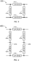
- FIG. 3 is a diagram view of a conventional branchline coupler 300 including quarter wave transformers 310a and 310b on 35 ⁇ lines and quarter wave transformers 320a and 320b on 50 ⁇ lines.
- FIG. 4 is a diagram view of a branchline coupler 400 that may be used with the present transmitter, in accordance with one or more embodiments of the present disclosure.
- the branchline coupler 400 may include quarter wave transformers 410a and 410b on 35 ⁇ lines and quarter wave transformers 420a-b and 425a-b on 50 ⁇ lines.
- Shunt p-type i-type- n-type (PIN) diode switches 430a-b may be inserted at the midpoint of each of the two 50 ⁇ lines.
- the PIN diode switches 430a-b may be diodes with a wide, undoped intrinsic (i-type) semiconductor region between a p-type semiconductor and an n-type semiconductor region. The p-type and n-type regions may be doped for use as Ohmic contacts. Under zero- or reverse-bias (the "off" state), a PIN diode has a low capacitance which does not pass an RF signal. Under a forward bias (the "on” state), a PIN diode may be an effective conductor of RF signals and allows them to pass.
- the PIN diode switches 430a-b may be controlled by a computer (e.g., coupler) such that a bias current controls the on and off states.
- RF relays can alternatively be used as switches, they switch relatively slowly (on the order of tens of milliseconds).
- the PIN diode switches 430a-b may switch relatively quickly (e.g., 1 microsecond), although at lower RF frequencies, the switching times may have a different order of magnitude as the RF period.
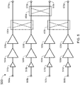
- FIG. 5 is a diagram view of a transmitter 500 for an aircraft (e.g., a TCAS transceiver and/or transponder).
- the transmitter may comprise a first channel, a second channel, a third channel, and a fourth channel, although the present disclosure is not limited to any particular number of channels.
- Each channel may include respective input ports 505a-d, one or more drive and power amplifiers 510a-d, 520a-d, and 530a-d configured to receive outgoing signals from the input ports 505a-d and amplify the outgoing signals, and output ports 570a-d configured to be coupled to radiating elements (e.g., antennas; not shown).
- radiating elements e.g., antennas; not shown.
- the radiating elements may be configured to receive the respective outgoing signals from the amplifier(s) 530a-d and transmit radio frequency (RF) signals in a respective direction (e.g., forward, aft, left, right, etc.) It is noted that the direction may be, for example, an azimuthal direction from the protected aircraft.
- the transmitter 500 may be able to transmit the combined power from all four power amplifiers 530a-d from a single port (e.g., connected to a blade antenna).
- the transmitter 500 may include branchline couplers 400a-d that are substantially similar or substantially identical to the branchline coupler 400 described with respect to FIG. 4 .
- the branchline couplers 400a-d may communicatively couple the channels such that signal transmission may be controlled between each channel.
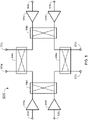
- the PIN diode switches 430a-b of coupler 400a may be configured to have a low impedance (e.g., by connecting the circuit to ground) and transmit the first outgoing signals of the first channel to the first antenna port, and the second outgoing signals of the second channel to the second antenna port, etc.
- the output RF beams are controlled with a digital beam former to adjust the relative phase of the four channels.
- the PIN diode switches 430a-b of coupler 400a may be configured to have a high impedance to transmit the first outgoing signals of the first channel to the first antenna port or the second antenna port, or the second outgoing signals of the second channel to the second antenna port or the first antenna port.
- the relative phase of the outgoing signals at the amplifiers e.g., amplifiers 530a-b
- the branchline couplers 400b and 400c may be substantially identical or substantially similar in structure and function to the branchline coupler 400a.
- each of the output ports 570a-d is communicatively coupled to a passive beamforming network (e.g., Butler matrix) when the transmitter 500 is in an amplitude-based mode.
- a passive beamforming network e.g., Butler matrix
- a controller e.g., computer or computing system including one or more processors and a memory may be communicatively coupled to the transmitter.
- Program instructions may be stored on the memory, that, when executed by the one or more processors, cause the one or more processors to perform functions, procedures, algorithms, methods, etc. described in the present disclosure.
- the controller may control the on-state and the off-state of the transmitter 500 by applying a bias current to the PIN diode switches of the branchline couplers 400a-c.
- the controller may adjust the phase of outgoing signals using digital beamforming (e.g., during the phase-based mode) or may adjust the phase of the outgoing signals at the amplifiers 530a-d (e.g., during the amplitude-based mode).
- FIG. 8 is a diagram view of an alternative transmitter 500.
- the transmitter 500 may include a fourth branchline coupler 400d that is substantially similar or substantially identical in form and function to the branchline couplers 400a-c described with respect to FIG. 5 .
- the fourth branchline coupler 400d may communicatively couple the first channel and the fourth channel.
- the alternative configuration of the transmitter 500 enables all four power amplifiers 530a-d to be combined and transmitted out of any of the four output ports 570a-d during the amplitude-based mode, or directly connected to their respective output port 570a-d during the phase-based mode.
Landscapes
- Engineering & Computer Science (AREA)
- Computer Networks & Wireless Communication (AREA)
- Signal Processing (AREA)
- Physics & Mathematics (AREA)
- Remote Sensing (AREA)
- Power Engineering (AREA)
- Fluid Mechanics (AREA)
- Astronomy & Astrophysics (AREA)
- Aviation & Aerospace Engineering (AREA)
- General Physics & Mathematics (AREA)
- Transmitters (AREA)
Abstract
Description
- The present disclosure is concerned with transmitters e.g. for an aircraft.
- A transmitter for an aircraft is disclosed in accordance with one or more illustrative embodiments of the present disclosure. In one illustrative embodiment, the transmitter comprises a first channel. The first channel comprises a first input port, one or more first power amplifiers configured to receive first outgoing signals from the first input port and amplify the first outgoing signals, and a first antenna port configured to receive the first outgoing signals from the first power amplifier(s), and transmit first radio frequency (RF) signals in a first direction. In another illustrative embodiment, the transmitter comprises a second channel. The second channel comprises a second input port, one or more second power amplifiers configured to receive second outgoing signals from the second input port and amplify the second outgoing signals, and a second antenna port configured to receive the second outgoing signals from the second power amplifier(s), and transmit second RF signals in a second direction. In another illustrative embodiment, the transmitter comprises a first branchline coupler communicatively coupled to the first channel and the second channel. The first branchline coupler comprises one or more first quarter wave transformers and a first set of p-type i-type n-type (PIN) diode switches. The first set of PIN diode switches is configured to have a high impedance to transmit at least one of the first outgoing signals or the second outgoing signals to form a first radiating beam or a second radiating beam responsive to the transmitter being in an amplitude-based mode. The first set of PIN diode switches is configured to have a low impedance and transmit the first outgoing signals to the first antenna port and the second outgoing signals to the second antenna port responsive to the transmitter being in a phase-based mode.
- It is to be understood that both the foregoing general description and the following detailed description are exemplary and explanatory only and are not necessarily restrictive of the invention as claimed. The accompanying drawings, which are incorporated in and constitute a part of the specification, illustrate embodiments of the invention and together with the general description, serve to explain the principles of the invention.
- The numerous advantages of the disclosure may be better understood by those skilled in the art by reference to the accompanying figures in which:
-
FIG. 1 is a diagram view of a conventional amplitude-based transmitter for an aircraft transponder. -
FIG. 2 is a diagram view of a conventional phase-based transmitter for an aircraft transponder. -
FIG. 3 is a diagram view of a conventional branchline coupler. -
FIG. 4 is a diagram view of a switched branchline coupler, in accordance with one or more embodiments of the present disclosure. -
FIG. 5 is a diagram view of a transmitter for an aircraft transponder including both a phase-based mode and an amplitude-based mode, in accordance with one or more embodiments of the present disclosure. -
FIG. 6 is a diagram view of a switched branchline coupler in a phase-based mode, in accordance with one or more embodiments of the present disclosure. -
FIG. 7 is a diagram view of a switched branchline coupler in an amplitude-based mode, in accordance with one or more embodiments of the present disclosure. -
FIG. 8 is a diagram view of an alternative of the transmitter shown inFIG. 5 , in accordance with one or more embodiments of the present disclosure. - Before explaining at least one embodiment of the inventive concepts disclosed herein in detail, it is to be understood that the inventive concepts are not limited in their application to the details of construction and the arrangement of the components or steps or methodologies set forth in the following description or illustrated in the drawings. In the following detailed description of embodiments of the present disclosure, numerous specific details are set forth in order to provide a more thorough understanding of the inventive concepts. However, it will be apparent to one of ordinary skill in the art having the benefit of the present disclosure that the inventive concepts disclosed herein may be practiced without these specific details. In other instances, well-known features may not be described in detail to avoid unnecessarily complicating the present disclosure. The inventive concepts disclosed herein are capable of other embodiments or of being practiced or carried out in various ways. Also, it is to be understood that the phraseology and terminology employed herein is for the purpose of description and should not be regarded as limiting.
- As used herein a letter following a reference numeral is intended to reference an embodiment of the feature or element that may be similar, but not necessarily identical, to a previously described element or feature bearing the same reference numeral (e.g., 1, 1a, 1b). Such shorthand notations are used for purposes of convenience only, and should not be construed to limit the inventive concepts disclosed herein in any way unless expressly stated to the contrary. Further, unless expressly stated to the contrary, "or" refers to an inclusive or and not to an exclusive or. For example, a condition A or B is satisfied by any one of the following: A is true (or present) and B is false (or not present), A is false (or not present) and B is true (or present), and both A and B are true (or present). In addition, use of the "a" or "an" are employed to describe elements and components of embodiments of the instant inventive concepts. This is done merely for convenience and to give a general sense of the inventive concepts, and "a" and "an" are intended to include one or at least one and the singular also includes the plural unless it is obvious that it is meant otherwise.
- Finally, as used herein any reference to "one embodiment" or "some embodiments" means that a particular element, feature, structure, or characteristic described in connection with the embodiment is included in at least one embodiment of the inventive concepts disclosed herein. The appearances of the phrase "in some embodiments" in various places in the specification are not necessarily all referring to the same embodiment, and embodiments of the inventive concepts disclosed may include one or more of the features expressly described or inherently present herein, or any combination or sub-combination of two or more such features, along with any other features which may not necessarily be expressly described or inherently present in the present disclosure.
- Traffic Collision Avoidance Systems (TCASs), also known as Aircraft or Airborne Collision Avoidance Systems (ACASs), operate with airborne transponders onboard protected aircraft. The TCAS periodically transmit interrogation signals to be received by transponders onboard other aircraft (e.g., target aircraft) in the vicinity of the protected aircraft. In reply to the interrogation signals (e.g., request signals), the target aircraft's transponder transmits a response signal. The typical transponder receiver receives the TCAS interrogation at 1030 MHz signals and transmits the reply at 1090 MHz signals. The TCAS equipment aboard the protected aircraft determines the range of the target aircraft by calculating the round trip time between transmission of the interrogation signal and reception of the response signal.
- A transponder is an airborne transmitter-receiver (i.e., transceiver) component of air traffic control Radar Beacon System mode A and mode C interrogations as well as mode S interrogations. A transponder sends an identifying coded signal in response to a received interrogation from a ground-based radar station or airborne TCAS system to locate and identify the aircraft. Reply signals from the transponder are used to generate displays of the replying aircraft identification, position, altitude, velocity, rate of altitude change, etc.
- Conventional airborne TCASs include two different approaches to form directional transmitter antenna patterns and angle of arrival determination: phase-based bearing estimation (e.g., phase-based TCAS) and amplitude comparing bearing estimation (amplitude-based TCAS). An example of an amplitude-based system is the ISS-2100 and an example of a phase-based system is the TTR-2100, both developed by Rockwell Collins, Inc. (Cedar Rapids, IA). Developing and maintaining two TCAS platforms is prohibitively expensive, since both platforms need to be extensively updated in order to enable modern TCAS/ACAS standards such as ACAS-X. Additionally, transitioning to a single platform (either amplitude or phase-based) for future applications is problematic since customers are required to change out their TCAS antennas from existing aircraft. Selecting a single platform is also problematic since both platforms have disadvantages. Thus, there is a need for a solution that advantageously integrates both platforms to reduce development and customer support burdens and is compatible with both phase and amplitude based antennas.
-
FIG. 1 is a diagram view of a conventional amplitude-based transmitter 100 (e.g., phased array) for an aircraft TCAS. The angle-of-arrive is calculated by comparing the amplitudes of the signals received from each channel (e.g., a first amplitude for the forward direction, a second amplitude for the aft direction, etc.).Driver amplifiers power amplifier 130 are configured to receive outgoing signals from aninput port 105 and amplify the outgoing signals.Quarter wave transformers 143a-d, 145a-d, and 147a-d apply an impedance transform and a 90° phase-shift to the outgoing signals.Switches 162a-d and 164a-d control which of theoutput ports 170a-d (e.g., antenna ports) transmits the outgoing signals. Each of theoutput ports 170a-d is communicatively coupled to a passive beamforming network (e.g., Butler matrix). The directional beam may then be transmitted by a radiating element of an antenna. The beam direction is controlled by switching between the fouroutputs ports 170a-d (e.g., after the outgoing signals are amplified by the single set ofamplifiers - Advantages of the conventional amplitude-based approach include cable phase calibration not being required and a single set of transmitter amplifiers (e.g., a single transmit channel). One disadvantage of the amplitude-based approach is the requirement of a 1-to-4 beam select switch for switching between the multiple output ports (e.g., antenna ports) which causes significant loss and increases power amplifier requirements. A single high power transmitter and switch is challenging to implement and has reliability issues, especially when mismatched (e.g., by impedance). Another disadvantage is the difficulty meeting the transponder A2 (250 Watt) requirement and the A3 (400 Watt) requirement. Additionally, the amplitude-based approach antenna is expensive since it requires a passive beam forming network (e.g., Butler matrix) and internal high power PIN diode switches for an omnidirectional beam. Furthermore, angle-of-arrive measurements are not as accurate as a phase-based system causing significant bearing errors on displayed targets.
-
FIG. 2 is a diagram view of a conventional phase-basedtransmitter 200 for an aircraft transponder. Phase-based TCAS utilizes four smaller transmitter/power amplifiers with digital beam forming. The angle-of-arrive is calculated by comparing the phases of the signals received from each channel (e.g., a first phase for the forward element, a second phase for the aft element, etc.). Each channel includes a respective set ofdriver amplifiers 210a-d and 220a-d andpower amplifiers 230a-d configured to receive respective outgoing signals from theinput ports 205a-d and amplify the outgoing signals. The relative phase of the four transmitters (sets of amplifiers) is adjusted in the digital domain to create the required beam. - Advantages of the phase-based approach include the use of four low-power transmitters (highly reliable), the omnidirectional beam requiring no additional hardware, the easier path to the A3 power requirement, and improved bearing accuracy. The phase-based approach presents several disadvantages. For one, it requires a complex cable calibration algorithm to determine the relative electrical length of each of the four RF cables between the TCAS radio and the antenna. Additionally, the phase-based approach does not support a single, directional top antenna with a bottom omnidirectional blade antenna without additional circuitry. This limitation is highly undesirable since about 40% of current ACAS configurations include a single directional antenna on the top of the aircraft with an omnidirectional blade antenna (e.g., omni-blade) on the bottom of the aircraft. Since the omni-blade is only connected to one of the four sets of power amplifiers, the power into the omni-blade is one quarter of the power into the directional antenna. In the near future, the ADS-B standard may make the dual directional antenna obsolete since the dual-directional antenna adds a significant addition of weight, drag and cost.
- Embodiments of the present disclosure are directed to a TCAS transmitter architecture that advantageously integrates both the phase-based and amplitude-based platforms. The present transmitter supports amplitude-based TCAS antennas for backwards compatibility, supports phase-based TCAS antennas (the preferred TCAS solution for all future traffic products), and supports bottom omni-blade antenna operation. In this way, aircraft that are currently equipped with either the phase-based platform or the amplitude-based platform do not require a complicated change of existing hardware or software.
-
FIG. 3 is a diagram view of aconventional branchline coupler 300 includingquarter wave transformers quarter wave transformers FIG. 4 is a diagram view of abranchline coupler 400 that may be used with the present transmitter, in accordance with one or more embodiments of the present disclosure. Thebranchline coupler 400 may includequarter wave transformers quarter wave transformers 420a-b and 425a-b on 50 Ω lines. Shunt p-type i-type- n-type (PIN)diode switches 430a-b may be inserted at the midpoint of each of the two 50 Ω lines. WhenPIN diode switches 430a-b have a high impedance, the circuit behaves like a standard branchline coupler. When the PIN diode is forward biased to create a short circuit, thecoupler 400 is effectively bypassed but maintains the correct 50 Ω match over the required pass band. - The
PIN diode switches 430a-b may be diodes with a wide, undoped intrinsic (i-type) semiconductor region between a p-type semiconductor and an n-type semiconductor region. The p-type and n-type regions may be doped for use as Ohmic contacts. Under zero- or reverse-bias (the "off" state), a PIN diode has a low capacitance which does not pass an RF signal. Under a forward bias (the "on" state), a PIN diode may be an effective conductor of RF signals and allows them to pass. ThePIN diode switches 430a-b may be controlled by a computer (e.g., coupler) such that a bias current controls the on and off states. Although RF relays can alternatively be used as switches, they switch relatively slowly (on the order of tens of milliseconds). In contrast, thePIN diode switches 430a-b may switch relatively quickly (e.g., 1 microsecond), although at lower RF frequencies, the switching times may have a different order of magnitude as the RF period. -
FIG. 5 is a diagram view of atransmitter 500 for an aircraft (e.g., a TCAS transceiver and/or transponder). The transmitter may comprise a first channel, a second channel, a third channel, and a fourth channel, although the present disclosure is not limited to any particular number of channels. Each channel may includerespective input ports 505a-d, one or more drive andpower amplifiers 510a-d, 520a-d, and 530a-d configured to receive outgoing signals from theinput ports 505a-d and amplify the outgoing signals, andoutput ports 570a-d configured to be coupled to radiating elements (e.g., antennas; not shown). The radiating elements may be configured to receive the respective outgoing signals from the amplifier(s) 530a-d and transmit radio frequency (RF) signals in a respective direction (e.g., forward, aft, left, right, etc.) It is noted that the direction may be, for example, an azimuthal direction from the protected aircraft. In some embodiments, thetransmitter 500 may be able to transmit the combined power from all fourpower amplifiers 530a-d from a single port (e.g., connected to a blade antenna). Thetransmitter 500 may includebranchline couplers 400a-d that are substantially similar or substantially identical to thebranchline coupler 400 described with respect toFIG. 4 . Thebranchline couplers 400a-d may communicatively couple the channels such that signal transmission may be controlled between each channel. - For example, as shown in
FIG. 6 , when thetransmitter 500 is in a phase-based mode, thePIN diode switches 430a-b ofcoupler 400a may be configured to have a low impedance (e.g., by connecting the circuit to ground) and transmit the first outgoing signals of the first channel to the first antenna port, and the second outgoing signals of the second channel to the second antenna port, etc. During the phase-based mode, the output RF beams are controlled with a digital beam former to adjust the relative phase of the four channels. - As shown in
FIG. 7 , when thetransmitter 500 is in an amplitude-based mode, thePIN diode switches 430a-b ofcoupler 400a may be configured to have a high impedance to transmit the first outgoing signals of the first channel to the first antenna port or the second antenna port, or the second outgoing signals of the second channel to the second antenna port or the first antenna port. To direct the RF beam out of the correct port, the relative phase of the outgoing signals at the amplifiers (e.g.,amplifiers 530a-b) may be adjusted. It is noted that thebranchline couplers branchline coupler 400a. For example, thebranchline coupler 400b may communicatively couple the second channel and the third channel, and thebranchline coupler 400c may communicatively couple the third channel and the fourth channel. In some embodiments, each of theoutput ports 570a-d is communicatively coupled to a passive beamforming network (e.g., Butler matrix) when thetransmitter 500 is in an amplitude-based mode. - In some embodiments, a controller (e.g., computer or computing system) including one or more processors and a memory may be communicatively coupled to the transmitter. Program instructions may be stored on the memory, that, when executed by the one or more processors, cause the one or more processors to perform functions, procedures, algorithms, methods, etc. described in the present disclosure. For example, in some embodiments, the controller may control the on-state and the off-state of the
transmitter 500 by applying a bias current to the PIN diode switches of thebranchline couplers 400a-c. In some embodiments, the controller may adjust the phase of outgoing signals using digital beamforming (e.g., during the phase-based mode) or may adjust the phase of the outgoing signals at theamplifiers 530a-d (e.g., during the amplitude-based mode). -
FIG. 8 is a diagram view of analternative transmitter 500. In some embodiments, thetransmitter 500 may include afourth branchline coupler 400d that is substantially similar or substantially identical in form and function to thebranchline couplers 400a-c described with respect toFIG. 5 . Thefourth branchline coupler 400d may communicatively couple the first channel and the fourth channel. In this way, the alternative configuration of thetransmitter 500 enables all fourpower amplifiers 530a-d to be combined and transmitted out of any of the fouroutput ports 570a-d during the amplitude-based mode, or directly connected to theirrespective output port 570a-d during the phase-based mode. - It is believed that the present disclosure and many of its attendant advantages will be understood by the foregoing description, and it will be apparent that various changes may be made within the scope of the invention defined by the appended claims.
Claims (7)
- A transmitter for an aircraft, comprising:a first channel, comprising:a first input port (505a),one or more first power amplifiers (510a, 520a, 530a) configured to receive first outgoing signals from the first input port and amplify the first outgoing signals, anda first antenna port (570a) configured to receive the first outgoing signals from the first power amplifier(s), and transmit first radio frequency (RF) signals in a first direction,a second channel, comprising:a second input port (505b),one or more second power amplifiers (510b, 520b, 530b) configured to receive second outgoing signals from the second input port and amplify the second outgoing signals, anda second antenna port (570b) configured to receive the second outgoing signals from the second power amplifier(s), and transmit second RF signals in a second direction,a first branchline coupler (400a) communicatively coupled to the first channel and the second channel, comprising:one or more first quarter wave transformers, anda first set of p-type i-type n-type PIN diode switches (430a),wherein the first set of PIN diode switches is configured to have a high impedance to transmit at least one of the first outgoing signals or the second outgoing signals to the first antenna port or the second antenna port responsive to the transmitter being in an amplitude-based mode,wherein the first set of PIN diode switches is configured to have a low impedance and transmit the first outgoing signals to the first antenna port and the second outgoing signals to the second antenna port responsive to the transmitter being in a phase-based mode.
- The transmitter of claim 1, further comprising:a third channel, comprising:a third input port (505c),one or more third power amplifiers (510c, 520c, 530c) configured to receive third outgoing signals from the third input port and amplify the third outgoing signals, anda third antenna port (570c) configured to receive the third outgoing signals from the third power amplifier(s), and transmit third RF signals in a third direction,a second branchline coupler (400b) communicatively coupled to the second channel and the third channel, comprising:one or more second quarter wave transformers, anda second set of PIN diode switches (430b),wherein the second set of PIN diode switches is configured to have a high impedance to transmit at least one of the second outgoing signals or the third outgoing signals to the second antenna port or the third antenna port responsive to the transmitter being in an amplitude-based mode,wherein the second set of PIN diode switches is configured to have a low impedance to transmit the second outgoing signals to the second antenna port and the third outgoing signals to the third antenna port responsive to the transmitter being in a phase-based mode.
- The transmitter of claim 2, further comprising:a fourth channel, comprising:a fourth input port (505d),one or more fourth power amplifiers (510d, 520d, 530d) configured to receive fourth outgoing signals from the fourth input port and amplify the fourth outgoing signals, anda fourth antenna port (570d) configured to receive the fourth outgoing signals from the fourth power amplifier(s), and transmit fourth radio frequency (RF) signals in a fourth direction,a third branchline coupler (400c) communicatively coupled to the third channel and the fourth channel, comprising:one or more third quarter wave transformers, anda third set of PIN diode switches,wherein the third set of PIN diode switches is configured to have a high impedance to transmit at least one of the third outgoing signals or the fourth outgoing signals to the third antenna port or the fourth antenna port responsive to the transmitter being in an amplitude-based mode,wherein the third set of PIN diode switches is configured to have a low impedance to transmit the third outgoing signals to the third antenna port and the fourth outgoing signals to the fourth antenna port responsive to the transmitter being in a phase-based mode.
- The transmitter of claim 3, comprising a fourth branchline coupler (400d) communicatively coupled to the first channel and the fourth channel, wherein the fourth branchline coupler comprises:one or more fourth quarter wave transformers, anda fourth set of PIN diode switches,wherein the fourth set of PIN diode switches is configured to have a high impedance to transmit at least one of the first outgoing signals or the fourth outgoing signals to the first antenna port or the fourth antenna port responsive to the transmitter being in an amplitude-based mode,wherein the fourth set of PIN diode switches is configured to have a low impedance to transmit the first outgoing signals to the first antenna port and the fourth outgoing signals to the fourth antenna port responsive to the transmitter being in a phase-based mode.
- The transmitter of claim 4, wherein the first direction is forward of the aircraft, the second direction is right of the aircraft, the third direction is aft of the aircraft, and the fourth direction is left of the aircraft.
- The transmitter of claim 4 or 5, wherein the transmitter being in the phase-based mode connects the first set of PIN diode switches, the second set of PIN diode switches, the third set of PIN diode switches, and the fourth set of PIN diode switches to ground.
- The transmitter of claim 4, 5 or 6, wherein at least one of the first antenna port, the second antenna port, the third radiating antenna port, or the fourth antenna port is connected to a blade antenna.
Applications Claiming Priority (1)
| Application Number | Priority Date | Filing Date | Title |
|---|---|---|---|
| US17/149,197 US11356134B1 (en) | 2021-01-14 | 2021-01-14 | Integrated TCAS/transponder transmitter architecture |
Publications (1)
| Publication Number | Publication Date |
|---|---|
| EP4030629A1 true EP4030629A1 (en) | 2022-07-20 |
Family
ID=80112300
Family Applications (1)
| Application Number | Title | Priority Date | Filing Date |
|---|---|---|---|
| EP22151667.7A Pending EP4030629A1 (en) | 2021-01-14 | 2022-01-14 | Integrated tcas/transponder transmitter architecture |
Country Status (2)
| Country | Link |
|---|---|
| US (1) | US11356134B1 (en) |
| EP (1) | EP4030629A1 (en) |
Families Citing this family (1)
| Publication number | Priority date | Publication date | Assignee | Title |
|---|---|---|---|---|
| TWI826096B (en) * | 2022-11-03 | 2023-12-11 | 財團法人工業技術研究院 | Switching circuit and method of providing switching circuit |
Citations (1)
| Publication number | Priority date | Publication date | Assignee | Title |
|---|---|---|---|---|
| US20090027258A1 (en) * | 2007-07-23 | 2009-01-29 | Stayton Gregory T | Systems and methods for antenna calibration |
Family Cites Families (18)
| Publication number | Priority date | Publication date | Assignee | Title |
|---|---|---|---|---|
| US6097266A (en) * | 1998-08-14 | 2000-08-01 | Lucent Technologies Inc | Intelligent RF combiner |
| US6313783B1 (en) | 1999-03-24 | 2001-11-06 | Honeywell International, Inc. | Transponder having directional antennas |
| KR100500663B1 (en) * | 2002-11-18 | 2005-07-12 | 한국전자통신연구원 | Switched coupler type digital phase shifter using quadrature generator |
| JP2007501397A (en) | 2003-08-05 | 2007-01-25 | ハワイ大学 | Microwave self-tuning antenna array for secure data transmission and satellite network cross-links |
| US7466670B2 (en) * | 2004-08-09 | 2008-12-16 | Cisco Technology, Inc. | Transmit system employing an antenna and balanced amplifier architecture which provides power amplifier load balancing independent of single or dual signal operation of the transmitter |
| US7436350B1 (en) | 2004-09-30 | 2008-10-14 | Rockwell Collins, Inc. | Combined aircraft TCAS/transponder with common antenna system |
| US7583223B2 (en) | 2006-09-18 | 2009-09-01 | Honeywell International Inc. | Distributed and Cable reduced TCAS |
| US20080219246A1 (en) | 2007-03-08 | 2008-09-11 | Northrop Grumman Space And Mission Systems Corp. | System and method for switching using coordinated phase shifters |
| US8019338B2 (en) * | 2008-05-29 | 2011-09-13 | Honeywell International Inc. | Reconfigurable aircraft communications system with integrated avionics communication router and audio management functions |
| EP2678902A4 (en) | 2011-02-25 | 2015-01-07 | Honeywell Int Inc | SYSTEMS AND METHODS FOR PROVIDING IMPROVED MEASUREMENT OF INLAND ANTICOLLISION SYSTEM DEPOSITION |
| US8933836B1 (en) | 2011-09-30 | 2015-01-13 | Rockwell Collins, Inc. | High speed angle-to-target estimation for a multiple antenna system and method |
| US9223019B2 (en) | 2012-10-25 | 2015-12-29 | Honeywell International Inc. | TCAS bearing estimation with reduced antenna elements |
| US9857461B2 (en) | 2013-10-14 | 2018-01-02 | Aviation Communication & Surveillance Systems Llc | Systems and methods for remote L-band smart antenna distance measuring equipment diversity |
| US9806394B2 (en) * | 2015-05-20 | 2017-10-31 | Mediatek Inc. | 0/90 degree coupler with complex termination |
| US10101447B2 (en) * | 2015-05-27 | 2018-10-16 | Garmin International, Inc. | Shared aviation antenna |
| US11480667B2 (en) * | 2016-01-22 | 2022-10-25 | Aviation Communication & Surveillance Systems Llc | Systems and methods for providing an integrated TCAS, transponder, and DME system using a dedicated DME antenna |
| US10958323B1 (en) * | 2020-03-25 | 2021-03-23 | Semiconductor Components Industries, Llc | MIMO radar system with dual mode output power amplification |
| US11038728B1 (en) * | 2020-10-01 | 2021-06-15 | Honeywell International Inc. | Demodulating surveillance signals |
-
2021
- 2021-01-14 US US17/149,197 patent/US11356134B1/en active Active
-
2022
- 2022-01-14 EP EP22151667.7A patent/EP4030629A1/en active Pending
Patent Citations (1)
| Publication number | Priority date | Publication date | Assignee | Title |
|---|---|---|---|---|
| US20090027258A1 (en) * | 2007-07-23 | 2009-01-29 | Stayton Gregory T | Systems and methods for antenna calibration |
Also Published As
| Publication number | Publication date |
|---|---|
| US11356134B1 (en) | 2022-06-07 |
Similar Documents
| Publication | Publication Date | Title |
|---|---|---|
| Lee et al. | Design and performance of a 24-GHz switch-antenna array FMCW radar system for automotive applications | |
| US8405541B2 (en) | Multi-range radar system | |
| US4742354A (en) | Radar transceiver employing circularly polarized waveforms | |
| US6184830B1 (en) | Compensation of direction finding estimates for polarimetric errors | |
| EP1901087B1 (en) | Distributed and cable reduced TCAS | |
| KR20170142560A (en) | Radar apparatus and Method for processing radar signal | |
| US11493620B2 (en) | Distributed monopulse radar antenna array for collision avoidance | |
| US7436350B1 (en) | Combined aircraft TCAS/transponder with common antenna system | |
| US10601132B2 (en) | Active phase switchable array | |
| US5208601A (en) | All-weather precision landing system for aircraft in remote areas | |
| AU8302891A (en) | Monopulse processing systems | |
| US8269684B2 (en) | Navigation, identification, and collision avoidance antenna systems | |
| US4670757A (en) | Bistatic object location method | |
| US5337058A (en) | Fast switching polarization diverse radar antenna system | |
| US11356134B1 (en) | Integrated TCAS/transponder transmitter architecture | |
| Sorrentino et al. | Accurate FMCW radar-based indoor localization system | |
| US12241971B2 (en) | Air traffic control antenna and system | |
| US4316190A (en) | Secondary surveillance radar | |
| Schwarz et al. | Improving the detection capability of imaging MIMO radars by TX beamforming | |
| KR102689273B1 (en) | Radar apparatus | |
| US7928894B1 (en) | Phased array radar with mutually orthogonal coding of transmitted and received V and H components | |
| US4107682A (en) | System for overcoming the effect of electronic countermeasures | |
| US6486839B1 (en) | Relative elevation detection for aircraft pilot warning system | |
| Lai et al. | ADS-B based collision avoidance radar for unmanned aerial vehicles | |
| US4975708A (en) | Time domain electronic antenna beam shaping |
Legal Events
| Date | Code | Title | Description |
|---|---|---|---|
| PUAI | Public reference made under article 153(3) epc to a published international application that has entered the european phase |
Free format text: ORIGINAL CODE: 0009012 |
|
| STAA | Information on the status of an ep patent application or granted ep patent |
Free format text: STATUS: THE APPLICATION HAS BEEN PUBLISHED |
|
| AK | Designated contracting states |
Kind code of ref document: A1 Designated state(s): AL AT BE BG CH CY CZ DE DK EE ES FI FR GB GR HR HU IE IS IT LI LT LU LV MC MK MT NL NO PL PT RO RS SE SI SK SM TR |
|
| STAA | Information on the status of an ep patent application or granted ep patent |
Free format text: STATUS: REQUEST FOR EXAMINATION WAS MADE |
|
| 17P | Request for examination filed |
Effective date: 20230120 |
|
| RBV | Designated contracting states (corrected) |
Designated state(s): AL AT BE BG CH CY CZ DE DK EE ES FI FR GB GR HR HU IE IS IT LI LT LU LV MC MK MT NL NO PL PT RO RS SE SI SK SM TR |