EP4030600B1 - Motor, camera module, and mobile terminal - Google Patents
Motor, camera module, and mobile terminal Download PDFInfo
- Publication number
- EP4030600B1 EP4030600B1 EP20880723.0A EP20880723A EP4030600B1 EP 4030600 B1 EP4030600 B1 EP 4030600B1 EP 20880723 A EP20880723 A EP 20880723A EP 4030600 B1 EP4030600 B1 EP 4030600B1
- Authority
- EP
- European Patent Office
- Prior art keywords
- eccentricity
- motor
- base
- prevention
- support base
- Prior art date
- Legal status (The legal status is an assumption and is not a legal conclusion. Google has not performed a legal analysis and makes no representation as to the accuracy of the status listed.)
- Active
Links
Images







Classifications
-
- H—ELECTRICITY
- H02—GENERATION; CONVERSION OR DISTRIBUTION OF ELECTRIC POWER
- H02K—DYNAMO-ELECTRIC MACHINES
- H02K41/00—Propulsion systems in which a rigid body is moved along a path due to dynamo-electric interaction between the body and a magnetic field travelling along the path
- H02K41/02—Linear motors; Sectional motors
- H02K41/035—DC motors; Unipolar motors
- H02K41/0352—Unipolar motors
- H02K41/0354—Lorentz force motors, e.g. voice coil motors
- H02K41/0356—Lorentz force motors, e.g. voice coil motors moving along a straight path
-
- F—MECHANICAL ENGINEERING; LIGHTING; HEATING; WEAPONS; BLASTING
- F03—MACHINES OR ENGINES FOR LIQUIDS; WIND, SPRING, OR WEIGHT MOTORS; PRODUCING MECHANICAL POWER OR A REACTIVE PROPULSIVE THRUST, NOT OTHERWISE PROVIDED FOR
- F03G—SPRING, WEIGHT, INERTIA OR LIKE MOTORS; MECHANICAL-POWER PRODUCING DEVICES OR MECHANISMS, NOT OTHERWISE PROVIDED FOR OR USING ENERGY SOURCES NOT OTHERWISE PROVIDED FOR
- F03G7/00—Mechanical-power-producing mechanisms, not otherwise provided for or using energy sources not otherwise provided for
- F03G7/06—Mechanical-power-producing mechanisms, not otherwise provided for or using energy sources not otherwise provided for using expansion or contraction of bodies due to heating, cooling, moistening, drying or the like
- F03G7/061—Mechanical-power-producing mechanisms, not otherwise provided for or using energy sources not otherwise provided for using expansion or contraction of bodies due to heating, cooling, moistening, drying or the like characterised by the actuating element
- F03G7/0614—Mechanical-power-producing mechanisms, not otherwise provided for or using energy sources not otherwise provided for using expansion or contraction of bodies due to heating, cooling, moistening, drying or the like characterised by the actuating element using shape memory elements
- F03G7/06143—Wires
-
- F—MECHANICAL ENGINEERING; LIGHTING; HEATING; WEAPONS; BLASTING
- F03—MACHINES OR ENGINES FOR LIQUIDS; WIND, SPRING, OR WEIGHT MOTORS; PRODUCING MECHANICAL POWER OR A REACTIVE PROPULSIVE THRUST, NOT OTHERWISE PROVIDED FOR
- F03G—SPRING, WEIGHT, INERTIA OR LIKE MOTORS; MECHANICAL-POWER PRODUCING DEVICES OR MECHANISMS, NOT OTHERWISE PROVIDED FOR OR USING ENERGY SOURCES NOT OTHERWISE PROVIDED FOR
- F03G7/00—Mechanical-power-producing mechanisms, not otherwise provided for or using energy sources not otherwise provided for
- F03G7/06—Mechanical-power-producing mechanisms, not otherwise provided for or using energy sources not otherwise provided for using expansion or contraction of bodies due to heating, cooling, moistening, drying or the like
- F03G7/066—Actuator control or monitoring
- F03G7/0665—Actuator control or monitoring controlled displacement, e.g. by using a lens positioning actuator
-
- G—PHYSICS
- G02—OPTICS
- G02B—OPTICAL ELEMENTS, SYSTEMS OR APPARATUS
- G02B27/00—Optical systems or apparatus not provided for by any of the groups G02B1/00 - G02B26/00, G02B30/00
- G02B27/64—Imaging systems using optical elements for stabilisation of the lateral and angular position of the image
- G02B27/646—Imaging systems using optical elements for stabilisation of the lateral and angular position of the image compensating for small deviations, e.g. due to vibration or shake
-
- G—PHYSICS
- G02—OPTICS
- G02B—OPTICAL ELEMENTS, SYSTEMS OR APPARATUS
- G02B7/00—Mountings, adjusting means, or light-tight connections, for optical elements
- G02B7/02—Mountings, adjusting means, or light-tight connections, for optical elements for lenses
- G02B7/04—Mountings, adjusting means, or light-tight connections, for optical elements for lenses with mechanism for focusing or varying magnification
- G02B7/09—Mountings, adjusting means, or light-tight connections, for optical elements for lenses with mechanism for focusing or varying magnification adapted for automatic focusing or varying magnification
-
- G—PHYSICS
- G03—PHOTOGRAPHY; CINEMATOGRAPHY; ANALOGOUS TECHNIQUES USING WAVES OTHER THAN OPTICAL WAVES; ELECTROGRAPHY; HOLOGRAPHY
- G03B—APPARATUS OR ARRANGEMENTS FOR TAKING PHOTOGRAPHS OR FOR PROJECTING OR VIEWING THEM; APPARATUS OR ARRANGEMENTS EMPLOYING ANALOGOUS TECHNIQUES USING WAVES OTHER THAN OPTICAL WAVES; ACCESSORIES THEREFOR
- G03B13/00—Viewfinders; Focusing aids for cameras; Means for focusing for cameras; Autofocus systems for cameras
- G03B13/32—Means for focusing
- G03B13/34—Power focusing
- G03B13/36—Autofocus systems
-
- G—PHYSICS
- G03—PHOTOGRAPHY; CINEMATOGRAPHY; ANALOGOUS TECHNIQUES USING WAVES OTHER THAN OPTICAL WAVES; ELECTROGRAPHY; HOLOGRAPHY
- G03B—APPARATUS OR ARRANGEMENTS FOR TAKING PHOTOGRAPHS OR FOR PROJECTING OR VIEWING THEM; APPARATUS OR ARRANGEMENTS EMPLOYING ANALOGOUS TECHNIQUES USING WAVES OTHER THAN OPTICAL WAVES; ACCESSORIES THEREFOR
- G03B3/00—Focusing arrangements of general interest for cameras, projectors or printers
-
- G—PHYSICS
- G03—PHOTOGRAPHY; CINEMATOGRAPHY; ANALOGOUS TECHNIQUES USING WAVES OTHER THAN OPTICAL WAVES; ELECTROGRAPHY; HOLOGRAPHY
- G03B—APPARATUS OR ARRANGEMENTS FOR TAKING PHOTOGRAPHS OR FOR PROJECTING OR VIEWING THEM; APPARATUS OR ARRANGEMENTS EMPLOYING ANALOGOUS TECHNIQUES USING WAVES OTHER THAN OPTICAL WAVES; ACCESSORIES THEREFOR
- G03B30/00—Camera modules comprising integrated lens units and imaging units, specially adapted for being embedded in other devices, e.g. mobile phones or vehicles
-
- G—PHYSICS
- G03—PHOTOGRAPHY; CINEMATOGRAPHY; ANALOGOUS TECHNIQUES USING WAVES OTHER THAN OPTICAL WAVES; ELECTROGRAPHY; HOLOGRAPHY
- G03B—APPARATUS OR ARRANGEMENTS FOR TAKING PHOTOGRAPHS OR FOR PROJECTING OR VIEWING THEM; APPARATUS OR ARRANGEMENTS EMPLOYING ANALOGOUS TECHNIQUES USING WAVES OTHER THAN OPTICAL WAVES; ACCESSORIES THEREFOR
- G03B5/00—Adjustment of optical system relative to image or object surface other than for focusing
-
- H—ELECTRICITY
- H04—ELECTRIC COMMUNICATION TECHNIQUE
- H04N—PICTORIAL COMMUNICATION, e.g. TELEVISION
- H04N23/00—Cameras or camera modules comprising electronic image sensors; Control thereof
- H04N23/60—Control of cameras or camera modules
- H04N23/68—Control of cameras or camera modules for stable pick-up of the scene, e.g. compensating for camera body vibrations
- H04N23/682—Vibration or motion blur correction
- H04N23/685—Vibration or motion blur correction performed by mechanical compensation
- H04N23/687—Vibration or motion blur correction performed by mechanical compensation by shifting the lens or sensor position
-
- G—PHYSICS
- G03—PHOTOGRAPHY; CINEMATOGRAPHY; ANALOGOUS TECHNIQUES USING WAVES OTHER THAN OPTICAL WAVES; ELECTROGRAPHY; HOLOGRAPHY
- G03B—APPARATUS OR ARRANGEMENTS FOR TAKING PHOTOGRAPHS OR FOR PROJECTING OR VIEWING THEM; APPARATUS OR ARRANGEMENTS EMPLOYING ANALOGOUS TECHNIQUES USING WAVES OTHER THAN OPTICAL WAVES; ACCESSORIES THEREFOR
- G03B2205/00—Adjustment of optical system relative to image or object surface other than for focusing
- G03B2205/0007—Movement of one or more optical elements for control of motion blur
-
- G—PHYSICS
- G03—PHOTOGRAPHY; CINEMATOGRAPHY; ANALOGOUS TECHNIQUES USING WAVES OTHER THAN OPTICAL WAVES; ELECTROGRAPHY; HOLOGRAPHY
- G03B—APPARATUS OR ARRANGEMENTS FOR TAKING PHOTOGRAPHS OR FOR PROJECTING OR VIEWING THEM; APPARATUS OR ARRANGEMENTS EMPLOYING ANALOGOUS TECHNIQUES USING WAVES OTHER THAN OPTICAL WAVES; ACCESSORIES THEREFOR
- G03B2205/00—Adjustment of optical system relative to image or object surface other than for focusing
- G03B2205/0053—Driving means for the movement of one or more optical element
- G03B2205/0076—Driving means for the movement of one or more optical element using shape memory alloys
Definitions
- This application relates to the field of camera technologies, and in particular, to a motor, a camera module, and a mobile terminal.
- Mobile terminals having a camera function such as smartphones and tablet computers, have increasingly high requirements for driving devices used therein, which are very important especially to autofocus (Auto Focus, AF for short) and optical image stabilization (Optical Image Stabilization, OIS for short) functions.
- autofocus Auto Focus, AF for short
- optical image stabilization Optical Image Stabilization, OIS for short
- OIS optical image stabilizers
- Drivers used in conventional OIS apparatuses include a voice coil motor (Voice Coil Motor, VCM for short) type OIS apparatus, a shape memory alloy (Shape memory alloy, shape memory alloy for short) type OIS apparatus, a VCM-shape memory alloy type OIS apparatus, a piezoelectric type OIS apparatus, or a stepper motor type OIS apparatus.
- VCM Voice Coil Motor
- shape memory alloy shape memory alloy
- VCM-shape memory alloy type OIS apparatus a piezoelectric type OIS apparatus
- stepper motor type OIS apparatus a stepper motor type OIS apparatus.
- shape memory alloy motor such as an eight-wire motor, which removes driving methods of other types such as electromagnetic and piezoelectric, and relies only on shape memory alloy wires to achieve AF and OIS functions.
- a shape memory alloy motor has advantages such as low costs, large thrust, long stroke, and no electromagnetic interference, and has wide application prospects.
- a rotor is suspended in the motor only by the shape memory alloy wires. When the shape memory alloy motor is powered on, the shape memory alloy wires are controlled to be energized to contract, and the position and posture of the motor rotor are changed.
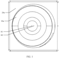
- the shape memory alloy wires When the shape memory alloy motor is powered off, the shape memory alloy wires get loose due to power outage, and the position and posture of the motor rotor are relatively free and may vary with the direction of gravity, resulting in a relatively large deviation between the center of thpe motor rotor and the central position of a motor stator. As shown in FIG 1 , there is a relatively large deviation, namely eccentricity, between a central axis A1 of a rotor 10a and a central axis A2 of a stator 20a, which affects the appearance of a camera module and a mobile terminal, and affects a product yield.
- WO 2017/069491 A1 disclose actuator for a camera module, in which a magnetic auto-focus actuator centers a lens element.
- Embodiments of this application provide a motor, a camera module, and a mobile terminal, to resolve a technical problem of reducing eccentricity.
- the present invention is defined by the independent claims.
- Advantageous implementations are defined in the dependent claims.
- embodiments which are not covered by the claims are to be considered as examples necessary for understanding the invention.
- an embodiment of this application provides a motor, including a base, a support base, and a shape memory alloy actuator.
- the support base and the base are disposed in a stacked manner.
- the shape memory alloy actuator is fixedly connected between the base and the support base, and the shape memory alloy actuator is configured to drive the support base to move relative to the base.
- the motor further includes an eccentricity-prevention magnetic assembly, the eccentricity-prevention magnetic assembly includes a first eccentricity-prevention member and a second eccentricity-prevention member, the first eccentricity-prevention member is disposed on the base, the second eccentricity-prevention member is disposed on the support base, and when the motor is in a powered-off state, a first central axis of the base coincides with a second central axis of the support base under the action of magnetostatic forces between the first eccentricity-prevention member and the second eccentricity-prevention member.
- the eccentricity-prevention magnetic assembly includes a first eccentricity-prevention member and a second eccentricity-prevention member, the first eccentricity-prevention member is disposed on the base, the second eccentricity-prevention member is disposed on the support base, and when the motor is in a powered-off state, a first central axis of the base coincides with a second central axis of the support base under the action of magnetostatic forces between the first eccentricity-prevention member and
- the shape memory alloy actuator can contract and deform when energized, so as to provide a driving force for the support base to move relative to the base.
- none of the shape memory alloy actuators are supplied with power. In other words, the shape memory alloy actuators cannot provide a driving force for the support base to move relative to the base.
- the first central axis of the base coincides with the second central axis of the support base, so that a possibility of the problem of eccentricity of the motor is reduced, and a product yield is improved.
- the first eccentricity-prevention member and the second eccentricity-prevention member have magnetostatic forces of attraction or repulsion therebetween.
- One of the first eccentricity-prevention member and the second eccentricity-prevention member is a magnet, and the other is a magnetizer; or both the first eccentricity-prevention member and the second eccentricity-prevention member are magnets.
- the motor has the function of preventing eccentricity while keeping the structure simple.
- the base has a first limiting portion, the first limiting portion is provided with a limiting groove, the support base has a second limiting portion, and the second limiting portion is accommodated in the limiting groove of the first limiting portion, so as to limit the movement of the support base relative to the base.
- the base further includes a baseplate, the first limiting portion protrudes from the baseplate, the baseplate is provided with a first accommodating hole corresponding to the second limiting portion, the first eccentricity-prevention member is accommodated in the first accommodating hole, the second eccentricity-prevention member is disposed on the second limiting portion, the first eccentricity-prevention member and the second eccentricity-prevention member have magnetostatic forces of attraction therebetween, and when the motor is in a powered-off state, a side of the second limiting portion facing the baseplate fits together with the baseplate.
- the first eccentricity-prevention member is built in the baseplate and not exposed from the base, so that the first eccentricity-prevention member is protected, and the movement of the support base relative to the base and the wiring of the motor are not affected.
- the baseplate is provided with a guide groove communicating with the limiting groove
- the bottom of the second limiting portion adjacent to the baseplate is provided with a guide protrusion
- the guide protrusion is accommodated in the guide groove when the motor is in a powered-off state.
- the guide protrusion is accommodated in the guide groove
- the first central axis of the base substantially coincides with the second central axis of the support base
- the support base is centered on the base
- the guide groove guides the movement of the support base relative to the base, thereby improving the accuracy of centering the motor.
- the base further includes a baseplate, the first limiting portion protrudes from the baseplate, the limiting groove extends through the baseplate, an end face of the first limiting portion away from the baseplate is provided with a first accommodating hole, and the first eccentricity-prevention member is accommodated in the first accommodating hole; the second eccentricity-prevention member is disposed on the second limiting portion, and when the motor is in a powered-off state, due to the action of the magnetostatic forces between the first eccentricity-prevention member and the second eccentricity-prevention member, part of an outer side wall of the first limiting portion fits together with a side wall of the limiting groove.
- the first eccentricity-prevention member is accommodated in the first accommodating hole, so that the first eccentricity-prevention member is protected, and the assembly of the motor is facilitated.
- the first eccentricity-prevention member is built in the baseplate and not exposed from the base, so that the movement of the support base relative to the base and the wiring of the motor are not affected.
- the second limiting portion is provided with a second accommodating hole, and the second eccentricity-prevention member is accommodated in the second accommodating hole.
- the second eccentricity-prevention member is built in the support base and not exposed from the support base, so that the second eccentricity-prevention member is protected, and the movement of the support base relative to the base is not affected.
- the motor further includes an eccentricity-prevention elastic structure fixedly connected between the support base and the base, the eccentricity-prevention elastic structure is configured to provide an elastic force for the base and the support base, so as to assist the eccentricity-prevention magnetic assembly in making the first central axis of the base coincide with the second central axis of the support base, or assist the shape memory alloy actuator in driving the support base to move relative to the base, to implement image stabilization and focusing.
- the support base further includes a connecting portion spaced apart from the second limiting portion, the shape memory alloy actuator is fixedly connected between the first limiting portion and the connecting portion, the eccentricity-prevention elastic structure is fixedly connected between the connecting portion and the first limiting portion, the connecting portion is provided with an abutting bump, the eccentricity-prevention elastic structure is provided with a slot, and the abutting protrusion is accommodated in the slot, which is beneficial to the improvement of connection stability between the eccentricity-prevention elastic structure and the support base.
- the eccentricity-prevention elastic structure includes a first elastic member and a second elastic member, each of the first elastic member and the second elastic member is fixedly connected between the base and the support base, and the first elastic member and the second elastic member are spaced apart along the first central axis of the base, so as to strengthen the elastic force of the eccentricity-prevention elastic structure.
- the eccentricity-prevention elastic structure is electrically connected to the shape memory alloy actuator as a common ground of the motor.
- the eccentricity-prevention elastic structure acts as an electrical connection while providing an elastic force for the support base, which is beneficial to simplification of the structure and wiring of the motor.
- the motor includes a plurality of side portions
- the first limiting portion includes two secondary mounting portions that are fixedly connected, and each secondary mounting portion is protruded with two first fastening terminals
- the connecting portion includes two secondary connecting portions that are fixedly connected, and each secondary connecting portion is provided with a second fastening terminal
- each side portion of the motor is correspondingly provided with two shape memory alloy actuators that are disposed crosswise, and each shape memory alloy is fastened between the first fastening terminal of one secondary mounting portion and the second fastening terminal of one secondary connecting portion.
- the eccentricity-prevention elastic structure is fastened to an end face of the connecting portion away from the baseplate and an end face of the first limiting portion away from the baseplate.
- an embodiment of this application further provides a camera module, including a lens and the motor described above, where the lens is fastened onto the support base.
- a first central axis of the base coincides with a second central axis of the support base, so that a possibility of the problem of eccentricity of the motor is reduced, and a yield of the camera module is improved.
- an embodiment of this application further provides a mobile terminal, including the camera module described above and a processor.
- the processor is configured to control to supply power to the shape memory alloy actuator, to drive the support base with the lens to move relative to the base for autofocus and image stabilization.
- a first central axis of the base coincides with a second central axis of the support base, so that a possibility of the problem of eccentricity of the motor is reduced, and a yield of the mobile terminal is improved.
- the processor is configured to control the magnitude of a current that is input to each shape memory alloy actuator, thereby driving the support base to move relative to the base.
- the processor is configured to control, for each shape memory alloy actuator, a voltage based on a duty cycle of pulse width modulation, thereby driving the support base to move relative to the base.
- the mobile terminal is one of a smartphone, a smart watch, a tablet computer, a personal digital assistant (personal digital assistant, PDA), or a notebook computer.
- a smartphone a smart watch
- a tablet computer a personal digital assistant (personal digital assistant, PDA)
- PDA personal digital assistant
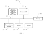
- FIG. 2 is a block diagram of a structure of a mobile terminal according to a first implementation of this application.
- the mobile terminal 200 includes a camera module 100, a processor 201, a communications bus 203, at least one communications interface 205, and a memory 206.
- the processor 201 is communicatively connected to the camera module 100, the at least one communications interface 205, and the memory 206 through the communications bus 203.
- the mobile terminal 100 may be any of various types of consumer electronic devices that can be easily held in a user's hand during normal use.
- the mobile terminal 100 may be an electronic device equipped with the camera module 100, such as a smartphone, a smart watch, a tablet computer, a personal digital assistant (personal digital assistant, PDA), or a notebook computer.
- PDA personal digital assistant
- the processor 201 may be a central processing unit (Central Processing Unit, CPU), or may be another general-purpose processor, a digital signal processor (Digital Signal Processor, DSP), an application-specific integrated circuit (Application Specific Integrated Circuit, ASIC), a field-programmable gate array (Field-Programmable Gate Array, FPGA), or another programmable logic device, a discrete gate or transistor logic device, a discrete hardware component, or the like.
- the general-purpose processor may be a microprocessor, or the processor may be any conventional processor or the like.
- the processor 201 is a control center of the mobile terminal 200, and connects all parts of the entire mobile terminal 200 through various interfaces and lines.
- the communications bus 203 may include a path for transferring information between the foregoing components.
- the communications interface 205 is any apparatus such as a transceiver, and is configured to communicate with another device or communications network, for example, the Ethernet, a radio access network (radio access network, RAN), or a wireless local area network (wireless local area network, WLAN).
- a radio access network radio access network, RAN
- a wireless local area network wireless local area network, WLAN
- the memory 206 may be configured to store a computer program and/or module, and the processor 201 implements various functions of the mobile terminal 200 by running or executing the computer program and/or module stored in the memory 206 and invoking data stored in the memory 206.
- the memory 206 may mainly include a program storage area and a data storage area.
- the program storage area may store an operating system, an application program (such as a sound playing function or an image playing function) that is required by a plurality of functions, and the like.
- the data storage area may store data (such as audio data or a phone book) that is created based on use of the terminal 200, and the like.
- the memory 206 may include a high-speed random access memory, and may further include a non-volatile memory such as a hard disk, an internal memory, and a removable hard disk, a smart media card (Smart Media Card, SMC), a secure digital (Secure Digital, SD) card, a flash card (Flash Card), a plurality of disk storage devices, a flash memory device, or another volatile solid-state storage device.
- the memory 206 may exist independently, and is connected to the processor 201 through the communications bus 203. Alternatively, the memory 206 may be integrated with the processor 201.
- the mobile terminal 200 may include a plurality of processors 201, for example, a CPU 0 and a CPU 1 in FIG. 2 .
- Each of the processors 201 may be a single-core (single-CPU) processor or a multi-core (multi-CPU) processor.
- the processor may be one or more devices, circuits, and/or processing cores configured to process data (for example, computer program instructions).
- the mobile terminal 200 further includes a speaker 207 and a display 208 that are electrically connected to the processor 201.
- FIG. 2 is merely an example of the mobile terminal 200, and does not constitute a limitation to the mobile terminal 200.
- the mobile terminal 200 may include more or fewer components than those shown in FIG. 2 , or some components may be combined, or there may be different components.
- the mobile terminal 200 may further include an input/output device, a network access device, and the like, which is not limited herein.
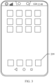
- FIG. 3 is a schematic diagram of an application scenario of a mobile terminal.
- the mobile terminal 200 is a consumer electronic device such as a smartphone.
- the processor 201 detects a trigger event corresponding to a virtual key 209 of a camera application
- the camera module 100 is controlled to start and enter a capturing interface (as shown in FIG. 4 ), to facilitate a user to capture an image.
- the camera module 100 may be a front-facing camera module of the mobile terminal 200 or a rear-facing camera module of the mobile terminal 200.
- the application scenario of the mobile terminal 200 shown in FIG. 3 and FIG. 4 is merely an example, which is not limited in this application.
- FIG. 5 is a schematic perspective view of assembly of a camera module of the mobile terminal according to the first implementation of this application.
- the camera module 100 includes a lens 10 and a motor 20.
- the lens 10 includes one or more lenses.
- the motor 20 includes a base 21, a support base 23, a shape memory alloy actuator 25, an eccentricity-prevention magnetic assembly 27, and an eccentricity-prevention elastic structure 29.
- the base 21 and the support base 23 are disposed in a stacked manner.
- the lens 10 is fastened onto the support base 21.
- the shape memory alloy actuator 25 is fixedly connected between the support base 21 and the base 23.
- the shape memory alloy actuator 25 is configured to drive the support base 23 to move relative to the base 21, thereby implementing the functions of autofocus and optical image stabilization.
- the eccentricity-prevention magnetic assembly 27 includes a first eccentricity-prevention member 271 fastened to the base 21 and a second eccentricity-prevention member 273 fastened to the support base 23.
- the first eccentricity-prevention member 271 and the second eccentricity-prevention member 273 have magnetostatic forces therebetween.
- the eccentricity-prevention elastic structure 29 is fixedly connected between the base 21 and the support base 23.
- a first central axis of the base 21 coincides with a second central axis of the support base 23, so that a possibility of the problem of eccentricity of the motor 20 is reduced.
- the first central axis of the base 21 may substantially coincide with the second central axis of the support base 23, which means that the motor 20 may be slightly eccentric due to errors, but this does not affect the appearance of the camera module 100.
- the motor 20 further includes a powered-on state.
- the processor 201 controls to supply power to the shape memory alloy actuators 25, and the shape memory alloy actuators 25 overcome the magnetostatic forces between the first eccentricity-prevention member 271 and the second eccentricity-prevention member 273 and the elastic force provided by the eccentricity-prevention elastic structure 29, to drive the support base 23 to move relative to the base 21.
- FIG. 7 is a schematic perspective exploded view of the camera module shown in FIG. 5 .
- the base 21 includes a baseplate 211 and a first limiting portion 213 protruding from the baseplate 211.
- the baseplate 211 is provided with a first through hole 2111.
- Each first limiting portion 213 is provided with a limiting groove 2131 on a side toward the first through hole 2111.
- Each first limiting portion 213 is further provided with a first fastening terminal 215 on an outer side wall away from the limiting groove 2131, where the first fastening terminal 215 is configured to fasten the shape memory alloy actuator 25.
- the baseplate 211 is provided with a first accommodating hole 2113 (as shown in FIG. 6 ) corresponding to a position of the limiting groove 2131, and the first eccentricity-prevention member 271 is fixedly accommodated in the first accommodating hole 2113.
- the support base 23 includes a base body 231, two second limiting portions 233, and two connecting portions 235.
- the base body 231 is provided with a second through hole 2311.
- the lens 10 passes through the second through hole 2311 and is fixedly connected to the base body 231.
- the two second limiting portions 233 and the two connecting portions 235 protrude at intervals from an outer wall of the base body 231 away from the second through hole 2311.
- Each second limiting portion 233 is accommodated in one limiting groove 2131.
- Each second limiting portion 233 is provided with a second accommodating hole 2333 (as shown in FIG. 6 ), and the second eccentricity-prevention member 273 is fastened in the second accommodating hole 2333.
- the bottom of the second limiting portion 233 facing the baseplate 211 fits together with the baseplate 211, and the first central axis of the base 21 coincides with the second central axis of support base 23.
- the structure and shape of the support base 23 are not limited.
- the support base 23 is substantially in the shape of a rectangular parallelepiped, and each of the two second limiting portions 233 and the two connecting portions 235 is a corner of the support base 23.
- Shape memory alloy (Shape memory alloy, shape memory alloy for short) is a general term for a class of metals with shape memory effect.
- shape memory alloy shape memory alloy, shape memory alloy for short
- a shape memory alloy material is an alloy material that can be heated to completely eliminate its deformation at a lower temperature and return to its original shape before deformation.
- a shape memory alloy has two states: one is the austenite phase at high temperature, which exists in the form of cubic crystals; the other is the martensite phase at low temperature, which exists in the form of monoclinic crystals.
- a transformation from austenite into martensite is referred to as a martensitic transformation, and a transformation from martensite into austenite is referred to as a reverse martensitic transformation.
- the basic operating principle of the shape memory alloy material is to heat the material to a critical temperature or higher for shape memory heat treatment (training), and make the material deform to some extent.
- the low-temperature martensite phase is reversed to the high-temperature austenite phase (that is, a reverse transformation occurs), so that the material returns to its remembered pre-deformed state.
- shape memory alloy wires are energized, and heat produced raises the temperature of the wires to implement the reverse transformation from the low-temperature martensite phase into the high-temperature austenite phase, recalling the memory before deformation.
- the wires contract and drive a related load component, to implement the focusing and image stabilization functions.
- the temperature of the wires decreases, and the wires get loose under the action of a resilience force of the load.
- the first eccentricity-prevention member 271 is a magnetizer
- the second eccentricity-prevention member 273 is a permanent magnet.
- the eccentricity-prevention elastic structure 29 is substantially ring-shaped.
- the eccentricity-prevention elastic structure 29 is fixedly connected between the support base 23 and the base 21.
- the eccentricity-prevention elastic structure 29 is fastened to an end face of the connecting portion 235 away from the baseplate 211 and an end face of the first limiting portion 213 away from the baseplate 211 by using an adhesive, so that the eccentricity-prevention elastic structure 29 is fixedly connected to the support base 23 and the base 21.
- the end face of the connecting portion 235 away from the baseplate 211 is further provided with an abutting bump 2353.
- the eccentricity-prevention elastic structure 29 is provided with a slot 291.
- the abutting bump 2353 is accommodated in the slot 291 to strengthen connection stability between the eccentricity-prevention elastic structure 29 and the support base 23.
- An opening of the slot 291 is disposed toward the center of the eccentricity-prevention elastic structure 29.
- the eccentricity-prevention elastic structure 29 is electrically connected to each of the shape memory alloy actuators 25 to serve as a common ground (common, namely common ground) of the motor 20.
- the eccentricity-prevention elastic structure 29 acts as an electrical connection while providing an elastic force for the support base 23, which is beneficial to simplification of the structure and wiring of the motor 60.
- the eccentricity-prevention elastic structure 29 may not be electrically connected to each of the shape memory alloy actuators 25; the shape of the eccentricity-prevention elastic structure 29 is not limited, and a quantity of eccentricity-prevention elastic structures 29 is not limited.
- the mobile terminal 200 When in use, the mobile terminal 200 may be placed vertically, horizontally, obliquely, or in another posture.
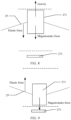
- the motor 20 is in a powered-on state, there is a relatively large distance between the first eccentricity-prevention member 271 and the second eccentricity-prevention member 273, and the direction of gravity received by the first eccentricity-prevention member 271 is opposite to that of a magnetostatic force received by the first eccentricity-prevention member 271 from the second eccentricity-prevention member 273.
- the processor 201 controls the motor 20 to be powered off.
- the eccentricity-prevention elastic structure 29 may provide an elastic force in the same direction as the magnetostatic force, so that the support base 23 moves toward the base 21 and fits together with the base 21.
- the motor 20 is in a powered-off state, and the base 21 and the support base 23 are in close contact.
- the processor 201 controls to supply power to the shape memory alloy actuator 25, if a magnetostatic force between the first eccentricity-prevention member 271 and the second eccentricity-prevention member 273 is relatively large, and a driving force provided by the shape memory alloy actuator 25 is not enough to overcome the magnetostatic force, the direction of an elastic force of the eccentricity-prevention elastic structure 29 is opposite to that of the magnetostatic force. Refer to FIG. 9 .
- the eccentricity-prevention elastic structure 29 provides assistance to the shape memory alloy actuator 25, so that the support base 23 is separated from the base 21 to implement the image stabilization and focusing functions.
- the direction of gravity, the direction of magnetostatic force, and the direction of elastic force in FIG. 8 and FIG. 9 are merely an example.
- the eccentricity-prevention elastic structure 29 can assist the eccentricity-prevention magnetic assembly 27 in making the first central axis of the base 21 coincide with the second central axis of the support base 23, or assist the shape memory alloy actuator 25 in driving the support base 23 to move relative to the base 21, to implement image stabilization and focusing.
- the first accommodating hole 2113 is omitted, and the first eccentricity-prevention member 271 is directly fastened to the baseplate 211 of the base 21 or another portion; the second accommodating hole 2333 is omitted, and the second eccentricity-prevention member 273 is directly fastened to the second limiting portion 233 of the support base 23 or another portion.
- a magnetostatic force between the first eccentricity-prevention member 271 and the second eccentricity-prevention member 273 can cause the base 21 and the support base 23 to fit each other when the motor 20 is in a powered-off state, so that the first central axis of the base 21 can coincide with the second central axis of the support base 23.
- the baseplate 211 is substantially rectangular, the two first limiting portions 213 are disposed on one diagonal line (first diagonal line) of the baseplate 211 and around the edge of the first through hole 211, and each of the first limiting portions 213 is located at one corner of the baseplate 211.
- the two connecting portions 235 are substantially located on the other diagonal line (second diagonal line) of the baseplate 211, and each connecting portion 235 is correspondingly disposed at one corner of the baseplate 211. In other words, each of the two connecting portions 235 and the two second limiting portions 233 is disposed corresponding to one corner of the baseplate 211.
- the first limiting portion 213 includes two secondary mounting portions 2135 (as shown in FIG. 7 ) that are fixedly connected.
- the two secondary mounting portions 2135 together form the limiting groove 2131.
- Each secondary mounting portion 2135 is protruded with two first fastening terminals 215, where one first fastening terminal 215 is provided at an end of the secondary mounting portion 2135 adjacent to the baseplate 211, and the other first fastening terminal 215 is provided at an end of the secondary mounting portion 2135 away from the baseplate 211.
- the connecting portion 235 includes two secondary connecting portions 2351 that are fixedly connected and disposed away from the second through hole 2311.
- Each secondary connecting portion 2351 is provided with two second fastening terminals 237, where one second fastening terminal 237 is provided at an end of the secondary connecting portion 2351 adjacent to the baseplate 211, and the other second fastening terminal 237 is provided at an end of the secondary connecting portion 2351 away from the baseplate 211.
- Each shape memory alloy actuator 25 is fixedly connected between one first fastening terminal 215 and one second fastening terminal 237.
- the motor 20 has four side portions; the two secondary mounting portions 2135 of each first limiting portion 213 are substantially perpendicular to each other, and the two secondary connecting portions 2351 of each connecting portion 235 are substantially perpendicular to each other. Therefore, each secondary mounting portion 2135 and a corresponding secondary connecting portion 2351 are disposed on the same side of the motor 20. Two shape memory alloy actuators 25 on the same side of the motor 20 are disposed crosswise.
- FIG. 10 is a schematic diagram of a structure of the motor.
- the support base 23 is represented by a rectangular structure in FIG. 10 .
- the base 21 is omitted in FIG. 10 .
- Eight shape memory alloy actuators that are equal in length and symmetrical in distribution are each connected between the first fastening terminal 215 of the base 21 and the second fastening terminal 237 of the support base 23.
- the shape memory alloy actuator 25 includes a number 1 actuator 251, a number 2 actuator 252, a number 3 actuator 253, a number 4 actuator 254, a number 5 actuator 255, a number 6 actuator 256, a number 7 actuator 257, and a number 8 actuator 258.
- the processor 201 is configured to control to supply power to the number 1 actuator 251, the number 2 actuator 252, the number 3 actuator 253, the number 4 actuator 254, the number 5 actuator 255, the number 6 actuator 256, the number 7 actuator 257, and the number 8 actuator 258. It can be understood that the processor 201 may control the magnitude of a current that is input to each shape memory alloy actuator 25, or may control, for each shape memory alloy actuator 25, a voltage based on a duty cycle of pulse width modulation, to implement the functions of the camera module 100 of automatic optical image stabilization and focusing.
- the quantity and arrangement of the shape memory alloy actuators 25 are not limited, as long as they can drive the support base 23 to move relative to the base 21.
- the arrangement of the eccentricity-prevention magnetic assembly 27 on the base 21 and the support base 23 is not limited, as long as the action of the magnetic force of the eccentricity-prevention magnetic assembly 27 on the support base 23 and the base 21 causes the first central axis of the base 21 to coincide with the second central axis of the support base 23.
- the support base (rotor) 23 and the base (stator) 21 keep in close contact at any posture, and there is no eccentricity.
- the shape memory alloy actuator 25 SMA wire
- a pulling force of the shape memory alloy actuator 25 overcomes the magnetostatic force and/or the elastic force to separate the support base 23 of the motor 20 from the base (stator) 21.
- the support base 23 is in an eight-wire suspension state, and the autofocus (AF) and optical image stabilization (OIS) actions are completed in this state.
- FIG. 11 is a schematic perspective view of assembly of a motor according to a second implementation of this application
- FIG. 12 is a schematic perspective exploded view of the motor shown in FIG. 11
- FIG. 13 is a perspective sectional view of the motor shown in FIG. 11 .
- the structure of the motor 40 provided in the second implementation is substantially the same as that of the motor 20 provided in the first implementation, except that the eccentricity-prevention elastic structure is omitted in the motor 40.
- each eccentricity-prevention magnetic assembly 47 includes a first eccentricity-prevention member 471 and a second eccentricity-prevention member 473.
- a first eccentricity-prevention member 471 is accommodated in a first accommodating hole 4113
- a second eccentricity-prevention member 473 is accommodated in a corresponding second accommodating hole 4331
- the first eccentricity-prevention member 471 and the second eccentricity-prevention member 473 have magnetostatic forces of attraction therebetween.
- the first eccentricity-prevention member 471 is a magnetizer
- the second eccentricity-prevention member 473 is a permanent magnet
- each eccentricity-prevention magnetic assembly 47 has one first eccentricity-prevention member 471 and one second eccentricity-prevention member 473.
- first eccentricity-prevention member 471 is built in the base 41
- second eccentricity-prevention member 473 is built in the support base 43, so that the movement of the support base 43 relative to the base 41 and the wiring of the motor are not easily affected.
- FIG. 14 is a schematic perspective view of assembly of a motor according to a third implementation of this application
- FIG. 15 is a schematic perspective exploded view of the motor shown in FIG. 14
- the structure of the motor 50 provided in the third implementation is substantially the same as that of the motor 20 provided in the first implementation, except that the eccentricity-prevention elastic structure is omitted in the motor 50.
- the motor 50 includes a base 51, a support base 53, a shape memory alloy actuator (not shown in the figure), and an eccentricity-prevention magnetic assembly 57.
- the base 51 includes a baseplate 511 and a first limiting portion 513 protruding from the baseplate 511.
- the baseplate 511 is provided with a first through hole 5111.
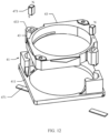
- the first limiting portion 513 is provided with a limiting groove 5131 on a side toward the first through hole 5111, and the limiting groove 5131 extends through the baseplate 511 and communicate with the first through hole 5111.
- the first limiting portion 513 is provided with a first accommodating hole 5131 on an end face away from the baseplate 511.
- the first accommodating hole 5133 is spaced apart from the limiting groove 5131. It can be understood that the first accommodating hole 5131 may communicate with the limiting groove 5131.
- the support base 53 is substantially square, and the support base 53 has a second limiting portion 533.
- the second limiting portion 533 is accommodated in the first limiting portion 513.
- the second limiting portion 533 is provided with a second accommodating hole 5331.
- the eccentricity-prevention magnetic assembly 57 includes a first eccentricity-prevention member 571 and a second eccentricity-prevention member 573, the first eccentricity-prevention member 571 is fixedly accommodated in the first accommodating hole 5133, and the second eccentricity-prevention member 573 is fixedly accommodated in the second accommodating hole 5331.
- Both the first eccentricity-prevention member 571 and the second eccentricity-prevention member 573 are permanent magnets, and the first eccentricity-prevention member 571 and the second eccentricity-prevention member 573 each have a first magnetic pole (for example, N pole) and a second magnetic pole (for example, S pole).
- the first magnetic pole of the first eccentricity-prevention member 571 and the second magnetic pole of the second eccentricity-prevention member 573 are disposed adjacent to each other, and the first eccentricity-prevention member 571 and the second eccentricity-prevention member 573 attract each other.
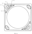
- the support base 53 and the base 51 are subject to the action of the magnetostatic forces of attraction between the first eccentricity-prevention member 571 and the second eccentricity-prevention member 573, and part of an outer side wall of the second limiting portion 533 and part of an inner side wall of the limiting groove 5131 of the base 51 are in close contact (in side-by-side close contact), as shown in FIG. 16 , so that a first central axis of the base 51 coincides with a second central axis of the support base 53.
- one of shape memory alloy actuators is energized to contract to provide a driving force to the support base 53, pulling the support base 53 to overcome the magnetostatic forces, and the support base 53 is separated from the base 51, as shown in FIG. 17 .
- one of the first eccentricity-prevention member 571 and the second eccentricity-prevention member 573 is a magnet, and the other is a magnetizer.
- FIG. 18 is a schematic perspective exploded view of a motor according to a fourth implementation of this application.
- the structure of the motor 60 provided in the fourth implementation is substantially the same as that of the motor 20 provided in the first implementation, except that the eccentricity-prevention magnetic assembly is omitted in the motor 60.
- an eccentricity-prevention elastic structure of the motor 60 includes two first elastic members 691 and two second elastic members 693.
- Each first elastic member 691 is fastened between a base 61 and a support base 63 of the motor 60
- each second elastic member 693 is fastened between the base 61 and the support base 63 of the motor 60, where the second elastic member 693 is located between the first elastic member 691 and a baseplate 611 of the base 61.
- Both the first elastic member 691 and the second elastic member 693 are substantially arc-shaped.
- the two first elastic members 691 substantially form a ring shape, to provide a relatively uniform elastic force to the base 61 and the support base 63.
- the first elastic member 691 and the second elastic member 693 are spaced apart in the direction of a first central axis of the base 61.
- the two second elastic members 693 substantially form a ring shape, to provide a relatively uniform elastic force to the base 61 and the support base 63.
- the second elastic member 693 also serves as a common ground (common) of the motor 60.
- the second elastic member 693 replaces the common ground for electrical conduction in the original eight-wire motor, so as to provide for an electrical connection while the first central axis of the base 61 substantially coincides with a second central axis of the support base 63, which is beneficial to simplification of the structure and wiring of the motor 60.
- the first elastic member 691 may be omitted, the quantity and shape of the first elastic members 691 are not limited, and the quantity and shape of the second elastic members 691 are not limited.
- the first elastic member 691 (upper elastic sheet) and the second elastic member 693 (lower elastic sheet) are added to the motor 60, and the second elastic member 693 is used to replace the common ground.
- the first elastic member 691 and the second elastic member 693 can provide an elastic force for the support base 63 (rotor) of the motor 60 to keep the support base 63 in the centered state, which greatly resolves the problem of eccentricity.
- FIG. 19 is a perspective sectional view of a motor according to a fifth implementation of this application.
- the structure of the motor 70 provided in the fifth embodiment is substantially the same as that of the motor 20 provided in the first implementation, except that a baseplate 711 of a base 71 is provided with a guide groove 7112 communicating with a limiting groove 7131.
- a first accommodating hole 7113 is provided in a side wall of the guide groove 7112.
- a first eccentricity-prevention member 771 is accommodated in the first accommodating hole 7113.
- a guide protrusion 7331 is provided on the bottom of a second limiting portion 733 of a support base 73 facing the baseplate 711. The guide protrusion 7331 can be accommodated in the guide groove 7112.
- the guide protrusion 7331 is substantially V-shaped, which makes it easier for the guide protrusion 7331 to enter the guide groove 7112, and improves the accuracy of centering the support base 73. It can be understood that the shape of the guide groove 7112 is not limited.
- the guide protrusion 7331 is accommodated in the guide groove 7112, and a first central axis of the base 71 coincides with a second central axis of the support base 73.
- the guide protrusion 7331 is separated from the guide groove 7112, and the support base 73 is suspended above the base 71 for autofocus and image stabilization.
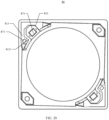
- FIG. 20 is a top view of a motor in a powered-off state according to a sixth implementation of this application.
- the structure of the motor 80 provided in the sixth implementation is substantially the same as that of the motor 50 provided in the third implementation, except that a first magnetic pole (for example, the S pole shown in FIG. 20 ) of a first eccentricity-prevention member 871 and a first magnetic pole (for example, the S pole shown in FIG. 20 ) of a second eccentricity-prevention member 873 are disposed adjacent to each other, that is, the first eccentricity-prevention member 871 and the second eccentricity-prevention member 873 have magnetostatic forces of repulsion therebetween.
- a first magnetic pole for example, the S pole shown in FIG. 20
- a first magnetic pole for example, the S pole shown in FIG. 20
- a first magnetic pole for example, the S pole shown in FIG. 20
- a support base 83 and a base 81 are subject to the action of the magnetostatic forces of repulsion between the first eccentricity-prevention member 871 and the second eccentricity-prevention member 873, and part of an outer side wall of a second limiting portion 833 and part of an inner side wall of a limiting groove 8131 of the base 81 are in close contact (in side-by-side close contact).
Landscapes
- Physics & Mathematics (AREA)
- Engineering & Computer Science (AREA)
- General Physics & Mathematics (AREA)
- Combustion & Propulsion (AREA)
- Chemical & Material Sciences (AREA)
- Electromagnetism (AREA)
- Power Engineering (AREA)
- Mechanical Engineering (AREA)
- General Engineering & Computer Science (AREA)
- Optics & Photonics (AREA)
- Multimedia (AREA)
- Signal Processing (AREA)
- Studio Devices (AREA)
- Lens Barrels (AREA)
- Adjustment Of Camera Lenses (AREA)
Description
- This application relates to the field of camera technologies, and in particular, to a motor, a camera module, and a mobile terminal.
- Mobile terminals having a camera function, such as smartphones and tablet computers, have increasingly high requirements for driving devices used therein, which are very important especially to autofocus (Auto Focus, AF for short) and optical image stabilization (Optical Image Stabilization, OIS for short) functions.
- Therefore, optical image stabilizers (OIS) are often employed in high-quality image camera lenses to prevent image damage caused by hand shaking during photography. Drivers used in conventional OIS apparatuses include a voice coil motor (Voice Coil Motor, VCM for short) type OIS apparatus, a shape memory alloy (Shape memory alloy, shape memory alloy for short) type OIS apparatus, a VCM-shape memory alloy type OIS apparatus, a piezoelectric type OIS apparatus, or a stepper motor type OIS apparatus.
- In addition, there is a shape memory alloy motor, such as an eight-wire motor, which removes driving methods of other types such as electromagnetic and piezoelectric, and relies only on shape memory alloy wires to achieve AF and OIS functions. Such a motor has advantages such as low costs, large thrust, long stroke, and no electromagnetic interference, and has wide application prospects. A rotor is suspended in the motor only by the shape memory alloy wires. When the shape memory alloy motor is powered on, the shape memory alloy wires are controlled to be energized to contract, and the position and posture of the motor rotor are changed. When the shape memory alloy motor is powered off, the shape memory alloy wires get loose due to power outage, and the position and posture of the motor rotor are relatively free and may vary with the direction of gravity, resulting in a relatively large deviation between the center of thpe motor rotor and the central position of a motor stator. As shown in
FIG 1 , there is a relatively large deviation, namely eccentricity, between a central axis A1 of arotor 10a and a central axis A2 of astator 20a, which affects the appearance of a camera module and a mobile terminal, and affects a product yield. -
WO 2017/069491 A1 ,WO 2018/234573 A1 ,CN 107979259 A andWO 2017/191998 A1 disclose actuator for a camera module, in which a magnetic auto-focus actuator centers a lens element. - Embodiments of this application provide a motor, a camera module, and a mobile terminal, to resolve a technical problem of reducing eccentricity. The present invention is defined by the independent claims. Advantageous implementations are defined in the dependent claims. In the following description, embodiments which are not covered by the claims are to be considered as examples necessary for understanding the invention.
- To achieve the foregoing objective, implementations of this application use the following technical solutions.
- According to a first aspect, an embodiment of this application provides a motor, including a base, a support base, and a shape memory alloy actuator. The support base and the base are disposed in a stacked manner. The shape memory alloy actuator is fixedly connected between the base and the support base, and the shape memory alloy actuator is configured to drive the support base to move relative to the base. The motor further includes an eccentricity-prevention magnetic assembly, the eccentricity-prevention magnetic assembly includes a first eccentricity-prevention member and a second eccentricity-prevention member, the first eccentricity-prevention member is disposed on the base, the second eccentricity-prevention member is disposed on the support base, and when the motor is in a powered-off state, a first central axis of the base coincides with a second central axis of the support base under the action of magnetostatic forces between the first eccentricity-prevention member and the second eccentricity-prevention member.
- The shape memory alloy actuator can contract and deform when energized, so as to provide a driving force for the support base to move relative to the base. In the powered-off state, none of the shape memory alloy actuators are supplied with power. In other words, the shape memory alloy actuators cannot provide a driving force for the support base to move relative to the base.
- When the motor is in a powered-off state, due to the action of the magnetostatic forces between the first eccentricity-prevention member and the second eccentricity-prevention member, the first central axis of the base coincides with the second central axis of the support base, so that a possibility of the problem of eccentricity of the motor is reduced, and a product yield is improved.
The first eccentricity-prevention member and the second eccentricity-prevention member have magnetostatic forces of attraction or repulsion therebetween. One of the first eccentricity-prevention member and the second eccentricity-prevention member is a magnet, and the other is a magnetizer; or both the first eccentricity-prevention member and the second eccentricity-prevention member are magnets. With the magnetostatic forces between the first eccentricity-prevention member and the second eccentricity-prevention member, the first central axis of the base coincides with the second central axis of the support base, and the eccentricity-prevention magnetic assembly has a simple structure. In this way, the motor has the function of preventing eccentricity while keeping the structure simple. - In an implementation, the base has a first limiting portion, the first limiting portion is provided with a limiting groove, the support base has a second limiting portion, and the second limiting portion is accommodated in the limiting groove of the first limiting portion, so as to limit the movement of the support base relative to the base.
- In an implementation, the base further includes a baseplate, the first limiting portion protrudes from the baseplate, the baseplate is provided with a first accommodating hole corresponding to the second limiting portion, the first eccentricity-prevention member is accommodated in the first accommodating hole, the second eccentricity-prevention member is disposed on the second limiting portion, the first eccentricity-prevention member and the second eccentricity-prevention member have magnetostatic forces of attraction therebetween, and when the motor is in a powered-off state, a side of the second limiting portion facing the baseplate fits together with the baseplate. The first eccentricity-prevention member is built in the baseplate and not exposed from the base, so that the first eccentricity-prevention member is protected, and the movement of the support base relative to the base and the wiring of the motor are not affected.
- In an implementation, the baseplate is provided with a guide groove communicating with the limiting groove, the bottom of the second limiting portion adjacent to the baseplate is provided with a guide protrusion, and the guide protrusion is accommodated in the guide groove when the motor is in a powered-off state. When the motor is in a powered-off state, under the action of the magnetostatic forces between the first eccentricity-prevention member and the second eccentricity-prevention member, the guide protrusion is accommodated in the guide groove, the first central axis of the base substantially coincides with the second central axis of the support base, the support base is centered on the base, and the guide groove guides the movement of the support base relative to the base, thereby improving the accuracy of centering the motor.
- In an implementation, the base further includes a baseplate, the first limiting portion protrudes from the baseplate, the limiting groove extends through the baseplate, an end face of the first limiting portion away from the baseplate is provided with a first accommodating hole, and the first eccentricity-prevention member is accommodated in the first accommodating hole; the second eccentricity-prevention member is disposed on the second limiting portion, and when the motor is in a powered-off state, due to the action of the magnetostatic forces between the first eccentricity-prevention member and the second eccentricity-prevention member, part of an outer side wall of the first limiting portion fits together with a side wall of the limiting groove.
- The first eccentricity-prevention member is accommodated in the first accommodating hole, so that the first eccentricity-prevention member is protected, and the assembly of the motor is facilitated. The first eccentricity-prevention member is built in the baseplate and not exposed from the base, so that the movement of the support base relative to the base and the wiring of the motor are not affected.
- In an implementation, the second limiting portion is provided with a second accommodating hole, and the second eccentricity-prevention member is accommodated in the second accommodating hole. In this way, the second eccentricity-prevention member is built in the support base and not exposed from the support base, so that the second eccentricity-prevention member is protected, and the movement of the support base relative to the base is not affected.
- In an implementation, the motor further includes an eccentricity-prevention elastic structure fixedly connected between the support base and the base, the eccentricity-prevention elastic structure is configured to provide an elastic force for the base and the support base, so as to assist the eccentricity-prevention magnetic assembly in making the first central axis of the base coincide with the second central axis of the support base, or assist the shape memory alloy actuator in driving the support base to move relative to the base, to implement image stabilization and focusing.
- In an implementation, the support base further includes a connecting portion spaced apart from the second limiting portion, the shape memory alloy actuator is fixedly connected between the first limiting portion and the connecting portion, the eccentricity-prevention elastic structure is fixedly connected between the connecting portion and the first limiting portion, the connecting portion is provided with an abutting bump, the eccentricity-prevention elastic structure is provided with a slot, and the abutting protrusion is accommodated in the slot, which is beneficial to the improvement of connection stability between the eccentricity-prevention elastic structure and the support base.
- In an implementation, the eccentricity-prevention elastic structure includes a first elastic member and a second elastic member, each of the first elastic member and the second elastic member is fixedly connected between the base and the support base, and the first elastic member and the second elastic member are spaced apart along the first central axis of the base, so as to strengthen the elastic force of the eccentricity-prevention elastic structure.
- In an implementation, the eccentricity-prevention elastic structure is electrically connected to the shape memory alloy actuator as a common ground of the motor. The eccentricity-prevention elastic structure acts as an electrical connection while providing an elastic force for the support base, which is beneficial to simplification of the structure and wiring of the motor.
- In an implementation, the motor includes a plurality of side portions, the first limiting portion includes two secondary mounting portions that are fixedly connected, and each secondary mounting portion is protruded with two first fastening terminals; the connecting portion includes two secondary connecting portions that are fixedly connected, and each secondary connecting portion is provided with a second fastening terminal; and each side portion of the motor is correspondingly provided with two shape memory alloy actuators that are disposed crosswise, and each shape memory alloy is fastened between the first fastening terminal of one secondary mounting portion and the second fastening terminal of one secondary connecting portion.
- In an implementation, the eccentricity-prevention elastic structure is fastened to an end face of the connecting portion away from the baseplate and an end face of the first limiting portion away from the baseplate.
- According to a second aspect, an embodiment of this application further provides a camera module, including a lens and the motor described above, where the lens is fastened onto the support base.
- When the motor is in a powered-off state, due to the action of a magnetic force of the eccentricity-prevention magnetic assembly, a first central axis of the base coincides with a second central axis of the support base, so that a possibility of the problem of eccentricity of the motor is reduced, and a yield of the camera module is improved.
- According to a third aspect, an embodiment of this application further provides a mobile terminal, including the camera module described above and a processor. The processor is configured to control to supply power to the shape memory alloy actuator, to drive the support base with the lens to move relative to the base for autofocus and image stabilization.
- When the motor is in a powered-off state, due to the action of a magnetic force of the eccentricity-prevention magnetic assembly, a first central axis of the base coincides with a second central axis of the support base, so that a possibility of the problem of eccentricity of the motor is reduced, and a yield of the mobile terminal is improved.
- In an implementation, the processor is configured to control the magnitude of a current that is input to each shape memory alloy actuator, thereby driving the support base to move relative to the base.
- In an implementation, the processor is configured to control, for each shape memory alloy actuator, a voltage based on a duty cycle of pulse width modulation, thereby driving the support base to move relative to the base.
- In an implementation, the mobile terminal is one of a smartphone, a smart watch, a tablet computer, a personal digital assistant (personal digital assistant, PDA), or a notebook computer.
-
-
FIG. 1 is a top view of a motor in a powered-off state in the conventional technology; -
FIG. 2 is a block diagram of a structure of a mobile terminal according to a first implementation of this application; -
FIG. 3 is a schematic diagram of an application scenario of a mobile terminal; -
FIG. 4 is a schematic diagram of the mobile terminal shown inFIG. 3 entering a camera interface; -
FIG. 5 is a schematic perspective view of assembly of a camera module according to the first implementation of this application; -
FIG. 6 is a perspective sectional view of the camera module shown inFIG. 5 ; -
FIG. 7 is a schematic perspective exploded view of the camera module shown inFIG. 5 ; -
FIG. 8 is a schematic force diagram of a partial structure of a motor in a powered-off state in an application scenario; -
FIG. 9 is a schematic force diagram of a partial structure of the motor in a powered-on state in another application scenario; -
FIG. 10 is a schematic diagram of a structure of the motor; -
FIG. 11 is a schematic perspective view of assembly of a motor according to a second implementation of this application; -
FIG. 12 is a schematic perspective exploded view of the motor shown inFIG. 11 ; -
FIG. 13 is a perspective sectional view of the motor shown inFIG. 11 ; -
FIG. 14 is a schematic perspective view of assembly of a motor according to a third implementation of this application; -
FIG. 15 is a schematic perspective exploded view of the motor shown inFIG. 14 ; -
FIG. 16 is a top view of the motor shown inFIG. 14 in a powered-off state; -
FIG. 17 is a top view of the motor shown inFIG. 14 in a powered-on state; -
FIG. 18 is a schematic perspective exploded view of a motor according to a fourth implementation of this application; -
FIG. 19 is a perspective sectional view of a motor according to a fifth implementation of this application; and -
FIG. 20 is a top view of a motor in a powered-off state according to a sixth implementation of this application. -
FIG. 2 is a block diagram of a structure of a mobile terminal according to a first implementation of this application. Themobile terminal 200 includes acamera module 100, aprocessor 201, acommunications bus 203, at least onecommunications interface 205, and amemory 206. Theprocessor 201 is communicatively connected to thecamera module 100, the at least onecommunications interface 205, and thememory 206 through thecommunications bus 203. Themobile terminal 100 may be any of various types of consumer electronic devices that can be easily held in a user's hand during normal use. Specifically, themobile terminal 100 may be an electronic device equipped with thecamera module 100, such as a smartphone, a smart watch, a tablet computer, a personal digital assistant (personal digital assistant, PDA), or a notebook computer. - The
processor 201 may be a central processing unit (Central Processing Unit, CPU), or may be another general-purpose processor, a digital signal processor (Digital Signal Processor, DSP), an application-specific integrated circuit (Application Specific Integrated Circuit, ASIC), a field-programmable gate array (Field-Programmable Gate Array, FPGA), or another programmable logic device, a discrete gate or transistor logic device, a discrete hardware component, or the like. The general-purpose processor may be a microprocessor, or the processor may be any conventional processor or the like. Theprocessor 201 is a control center of themobile terminal 200, and connects all parts of the entiremobile terminal 200 through various interfaces and lines. Thecommunications bus 203 may include a path for transferring information between the foregoing components. - The
communications interface 205 is any apparatus such as a transceiver, and is configured to communicate with another device or communications network, for example, the Ethernet, a radio access network (radio access network, RAN), or a wireless local area network (wireless local area network, WLAN). - The
memory 206 may be configured to store a computer program and/or module, and theprocessor 201 implements various functions of themobile terminal 200 by running or executing the computer program and/or module stored in thememory 206 and invoking data stored in thememory 206. Thememory 206 may mainly include a program storage area and a data storage area. The program storage area may store an operating system, an application program (such as a sound playing function or an image playing function) that is required by a plurality of functions, and the like. The data storage area may store data (such as audio data or a phone book) that is created based on use of the terminal 200, and the like. In addition, thememory 206 may include a high-speed random access memory, and may further include a non-volatile memory such as a hard disk, an internal memory, and a removable hard disk, a smart media card (Smart Media Card, SMC), a secure digital (Secure Digital, SD) card, a flash card (Flash Card), a plurality of disk storage devices, a flash memory device, or another volatile solid-state storage device. Thememory 206 may exist independently, and is connected to theprocessor 201 through thecommunications bus 203. Alternatively, thememory 206 may be integrated with theprocessor 201. - In specific implementation, in an embodiment, the
mobile terminal 200 may include a plurality ofprocessors 201, for example, aCPU 0 and aCPU 1 inFIG. 2 . Each of theprocessors 201 may be a single-core (single-CPU) processor or a multi-core (multi-CPU) processor. Herein, the processor may be one or more devices, circuits, and/or processing cores configured to process data (for example, computer program instructions). - In this implementation, the
mobile terminal 200 further includes aspeaker 207 and adisplay 208 that are electrically connected to theprocessor 201. It may be understood thatFIG. 2 is merely an example of themobile terminal 200, and does not constitute a limitation to themobile terminal 200. Themobile terminal 200 may include more or fewer components than those shown inFIG. 2 , or some components may be combined, or there may be different components. For example, themobile terminal 200 may further include an input/output device, a network access device, and the like, which is not limited herein. -
FIG. 3 is a schematic diagram of an application scenario of a mobile terminal. In an application scenario, themobile terminal 200 is a consumer electronic device such as a smartphone. When theprocessor 201 detects a trigger event corresponding to avirtual key 209 of a camera application, thecamera module 100 is controlled to start and enter a capturing interface (as shown inFIG. 4 ), to facilitate a user to capture an image. It can be understood that thecamera module 100 may be a front-facing camera module of themobile terminal 200 or a rear-facing camera module of themobile terminal 200. The application scenario of themobile terminal 200 shown inFIG. 3 andFIG. 4 is merely an example, which is not limited in this application. -
FIG. 5 is a schematic perspective view of assembly of a camera module of the mobile terminal according to the first implementation of this application. Thecamera module 100 includes alens 10 and amotor 20. Thelens 10 includes one or more lenses. Themotor 20 includes abase 21, asupport base 23, a shapememory alloy actuator 25, an eccentricity-preventionmagnetic assembly 27, and an eccentricity-preventionelastic structure 29. Thebase 21 and thesupport base 23 are disposed in a stacked manner. Thelens 10 is fastened onto thesupport base 21. The shapememory alloy actuator 25 is fixedly connected between thesupport base 21 and thebase 23. The shapememory alloy actuator 25 is configured to drive thesupport base 23 to move relative to thebase 21, thereby implementing the functions of autofocus and optical image stabilization. The eccentricity-preventionmagnetic assembly 27 includes a first eccentricity-prevention member 271 fastened to thebase 21 and a second eccentricity-prevention member 273 fastened to thesupport base 23. The first eccentricity-prevention member 271 and the second eccentricity-prevention member 273 have magnetostatic forces therebetween. The eccentricity-preventionelastic structure 29 is fixedly connected between the base 21 and thesupport base 23. - When the
motor 20 is in a powered-off state, due to the action of a magnetic force of the eccentricity-preventionmagnetic assembly 27 and an elastic force of the eccentricity-preventionelastic structure 29, a first central axis of thebase 21 coincides with a second central axis of thesupport base 23, so that a possibility of the problem of eccentricity of themotor 20 is reduced. The first central axis of the base 21 may substantially coincide with the second central axis of thesupport base 23, which means that themotor 20 may be slightly eccentric due to errors, but this does not affect the appearance of thecamera module 100. - In the powered-off state, none of the shape
memory alloy actuators 25 are energized. In other words, the shapememory alloy actuators 25 cannot provide a driving force for thesupport base 23 to move relative to thebase 21. Themotor 20 further includes a powered-on state. In the powered-on state, theprocessor 201 controls to supply power to the shapememory alloy actuators 25, and the shapememory alloy actuators 25 overcome the magnetostatic forces between the first eccentricity-prevention member 271 and the second eccentricity-prevention member 273 and the elastic force provided by the eccentricity-preventionelastic structure 29, to drive thesupport base 23 to move relative to thebase 21. - Referring also to
FIG. 7, FIG. 7 is a schematic perspective exploded view of the camera module shown inFIG. 5 . Thebase 21 includes abaseplate 211 and a first limiting portion 213 protruding from thebaseplate 211. Thebaseplate 211 is provided with a first throughhole 2111. Each first limiting portion 213 is provided with a limitinggroove 2131 on a side toward the first throughhole 2111. Each first limiting portion 213 is further provided with afirst fastening terminal 215 on an outer side wall away from the limitinggroove 2131, where thefirst fastening terminal 215 is configured to fasten the shapememory alloy actuator 25. Thebaseplate 211 is provided with a first accommodating hole 2113 (as shown inFIG. 6 ) corresponding to a position of the limitinggroove 2131, and the first eccentricity-prevention member 271 is fixedly accommodated in the firstaccommodating hole 2113. - The
support base 23 includes abase body 231, two second limitingportions 233, and two connectingportions 235. Thebase body 231 is provided with a second throughhole 2311. Thelens 10 passes through the second throughhole 2311 and is fixedly connected to thebase body 231. The two second limitingportions 233 and the two connectingportions 235 protrude at intervals from an outer wall of thebase body 231 away from the second throughhole 2311. Each second limitingportion 233 is accommodated in one limitinggroove 2131. Each second limitingportion 233 is provided with a second accommodating hole 2333 (as shown inFIG. 6 ), and the second eccentricity-prevention member 273 is fastened in the secondaccommodating hole 2333. When themotor 20 is in a powered-off state, due to the action of a magnetostatic force of the eccentricity-preventionmagnetic assembly 27 and elasticity of the eccentricity-preventionelastic structure 29, the bottom of the second limitingportion 233 facing thebaseplate 211 fits together with thebaseplate 211, and the first central axis of thebase 21 coincides with the second central axis ofsupport base 23. It can be understood that the structure and shape of thesupport base 23 are not limited. For example, thesupport base 23 is substantially in the shape of a rectangular parallelepiped, and each of the two second limitingportions 233 and the two connectingportions 235 is a corner of thesupport base 23. - There are eight shape
memory alloy actuators 25. Shape memory alloy (Shape memory alloy, shape memory alloy for short) is a general term for a class of metals with shape memory effect. When an ordinary metal material is subject to an external force, elastic deformation occurs first, and the metal returns to its original shape when the external force is removed. As the external force is increased to reach a yield point of the metal, plastic deformation occurs, in which permanent deformation remains after the external force is removed, and the metal does not return to its original shape even if heated. A shape memory alloy material is an alloy material that can be heated to completely eliminate its deformation at a lower temperature and return to its original shape before deformation. - It is generally believed that a shape memory alloy has two states: one is the austenite phase at high temperature, which exists in the form of cubic crystals; the other is the martensite phase at low temperature, which exists in the form of monoclinic crystals. A transformation from austenite into martensite is referred to as a martensitic transformation, and a transformation from martensite into austenite is referred to as a reverse martensitic transformation. The basic operating principle of the shape memory alloy material is to heat the material to a critical temperature or higher for shape memory heat treatment (training), and make the material deform to some extent. When the material is cooled to form the martensite phase and then is heated again to the critical temperature or higher, the low-temperature martensite phase is reversed to the high-temperature austenite phase (that is, a reverse transformation occurs), so that the material returns to its remembered pre-deformed state.
- In the application of the shape memory alloy material to a driving process of a motor, shape memory alloy wires are energized, and heat produced raises the temperature of the wires to implement the reverse transformation from the low-temperature martensite phase into the high-temperature austenite phase, recalling the memory before deformation. As a result, the wires contract and drive a related load component, to implement the focusing and image stabilization functions. When the power is stopped, the temperature of the wires decreases, and the wires get loose under the action of a resilience force of the load.
- The first eccentricity-
prevention member 271 is a magnetizer, and the second eccentricity-prevention member 273 is a permanent magnet. In this implementation, there are two eccentricity-preventionmagnetic assemblies 27, and each eccentricity-preventionmagnetic assembly 27 has two first eccentricity-prevention members 271 and one second eccentricity-prevention member 273. It can be understood that a quantity of eccentricity-preventionmagnetic assemblies 27 is not limited, and a quantity of first eccentricity-prevention members 271 and second eccentricity-prevention members 273 in the eccentricity-preventionmagnetic assembly 27 is not limited. - The eccentricity-prevention
elastic structure 29 is substantially ring-shaped. The eccentricity-preventionelastic structure 29 is fixedly connected between thesupport base 23 and thebase 21. In this implementation, the eccentricity-preventionelastic structure 29 is fastened to an end face of the connectingportion 235 away from thebaseplate 211 and an end face of the first limiting portion 213 away from thebaseplate 211 by using an adhesive, so that the eccentricity-preventionelastic structure 29 is fixedly connected to thesupport base 23 and thebase 21. The end face of the connectingportion 235 away from thebaseplate 211 is further provided with anabutting bump 2353. The eccentricity-preventionelastic structure 29 is provided with aslot 291. Theabutting bump 2353 is accommodated in theslot 291 to strengthen connection stability between the eccentricity-preventionelastic structure 29 and thesupport base 23. An opening of theslot 291 is disposed toward the center of the eccentricity-preventionelastic structure 29. - The eccentricity-prevention
elastic structure 29 is electrically connected to each of the shapememory alloy actuators 25 to serve as a common ground (common, namely common ground) of themotor 20. In other words, the eccentricity-preventionelastic structure 29 acts as an electrical connection while providing an elastic force for thesupport base 23, which is beneficial to simplification of the structure and wiring of themotor 60. It can be understood that the eccentricity-preventionelastic structure 29 may not be electrically connected to each of the shapememory alloy actuators 25; the shape of the eccentricity-preventionelastic structure 29 is not limited, and a quantity of eccentricity-preventionelastic structures 29 is not limited. - When in use, the
mobile terminal 200 may be placed vertically, horizontally, obliquely, or in another posture. For example, in an application scenario, as shown inFIG. 8 , themotor 20 is in a powered-on state, there is a relatively large distance between the first eccentricity-prevention member 271 and the second eccentricity-prevention member 273, and the direction of gravity received by the first eccentricity-prevention member 271 is opposite to that of a magnetostatic force received by the first eccentricity-prevention member 271 from the second eccentricity-prevention member 273. If thecamera module 100 does not require image stabilization and focusing, theprocessor 201 controls themotor 20 to be powered off. If a magnetostatic force between the first eccentricity-prevention member 271 and the second eccentricity-prevention member 273 is too small to overcome gravity received by thesupport base 23, and thebase 21 is in close contact with thesupport base 23, the eccentricity-preventionelastic structure 29 may provide an elastic force in the same direction as the magnetostatic force, so that thesupport base 23 moves toward thebase 21 and fits together with thebase 21. - For another example, in another application scenario, the
motor 20 is in a powered-off state, and thebase 21 and thesupport base 23 are in close contact. When thecamera module 100 requires image stabilization and focusing, theprocessor 201 controls to supply power to the shapememory alloy actuator 25, if a magnetostatic force between the first eccentricity-prevention member 271 and the second eccentricity-prevention member 273 is relatively large, and a driving force provided by the shapememory alloy actuator 25 is not enough to overcome the magnetostatic force, the direction of an elastic force of the eccentricity-preventionelastic structure 29 is opposite to that of the magnetostatic force. Refer toFIG. 9 . The eccentricity-preventionelastic structure 29 provides assistance to the shapememory alloy actuator 25, so that thesupport base 23 is separated from the base 21 to implement the image stabilization and focusing functions. The direction of gravity, the direction of magnetostatic force, and the direction of elastic force inFIG. 8 and FIG. 9 are merely an example. - In conclusion, the eccentricity-prevention
elastic structure 29 can assist the eccentricity-preventionmagnetic assembly 27 in making the first central axis of the base 21 coincide with the second central axis of thesupport base 23, or assist the shapememory alloy actuator 25 in driving thesupport base 23 to move relative to thebase 21, to implement image stabilization and focusing. - In an implementation, the first
accommodating hole 2113 is omitted, and the first eccentricity-prevention member 271 is directly fastened to thebaseplate 211 of the base 21 or another portion; the secondaccommodating hole 2333 is omitted, and the second eccentricity-prevention member 273 is directly fastened to the second limitingportion 233 of thesupport base 23 or another portion. A magnetostatic force between the first eccentricity-prevention member 271 and the second eccentricity-prevention member 273 can cause thebase 21 and thesupport base 23 to fit each other when themotor 20 is in a powered-off state, so that the first central axis of the base 21 can coincide with the second central axis of thesupport base 23. - In this implementation, still refer to
FIG. 7 . Thebaseplate 211 is substantially rectangular, the two first limiting portions 213 are disposed on one diagonal line (first diagonal line) of thebaseplate 211 and around the edge of the first throughhole 211, and each of the first limiting portions 213 is located at one corner of thebaseplate 211. The two connectingportions 235 are substantially located on the other diagonal line (second diagonal line) of thebaseplate 211, and each connectingportion 235 is correspondingly disposed at one corner of thebaseplate 211. In other words, each of the two connectingportions 235 and the two second limitingportions 233 is disposed corresponding to one corner of thebaseplate 211. - More specifically, the first limiting portion 213 includes two secondary mounting portions 2135 (as shown in
FIG. 7 ) that are fixedly connected. The twosecondary mounting portions 2135 together form the limitinggroove 2131. Eachsecondary mounting portion 2135 is protruded with twofirst fastening terminals 215, where onefirst fastening terminal 215 is provided at an end of thesecondary mounting portion 2135 adjacent to thebaseplate 211, and the otherfirst fastening terminal 215 is provided at an end of thesecondary mounting portion 2135 away from thebaseplate 211. The connectingportion 235 includes two secondary connectingportions 2351 that are fixedly connected and disposed away from the second throughhole 2311. Each secondary connectingportion 2351 is provided with twosecond fastening terminals 237, where onesecond fastening terminal 237 is provided at an end of the secondary connectingportion 2351 adjacent to thebaseplate 211, and the othersecond fastening terminal 237 is provided at an end of the secondary connectingportion 2351 away from thebaseplate 211. Each shapememory alloy actuator 25 is fixedly connected between onefirst fastening terminal 215 and onesecond fastening terminal 237. - In this implementation, the
motor 20 has four side portions; the twosecondary mounting portions 2135 of each first limiting portion 213 are substantially perpendicular to each other, and the two secondary connectingportions 2351 of each connectingportion 235 are substantially perpendicular to each other. Therefore, each secondary mountingportion 2135 and a corresponding secondary connectingportion 2351 are disposed on the same side of themotor 20. Two shapememory alloy actuators 25 on the same side of themotor 20 are disposed crosswise. -
FIG. 10 is a schematic diagram of a structure of the motor. Thesupport base 23 is represented by a rectangular structure inFIG. 10 . Thebase 21 is omitted inFIG. 10 . Eight shape memory alloy actuators that are equal in length and symmetrical in distribution are each connected between thefirst fastening terminal 215 of thebase 21 and thesecond fastening terminal 237 of thesupport base 23. The shapememory alloy actuator 25 includes anumber 1actuator 251, a number 2actuator 252, a number 3actuator 253, a number 4actuator 254, a number 5actuator 255, a number 6actuator 256, a number 7actuator 257, and a number 8actuator 258. Theprocessor 201 is configured to control to supply power to thenumber 1actuator 251, the number 2actuator 252, the number 3actuator 253, the number 4actuator 254, the number 5actuator 255, the number 6actuator 256, the number 7actuator 257, and the number 8actuator 258. It can be understood that theprocessor 201 may control the magnitude of a current that is input to each shapememory alloy actuator 25, or may control, for each shapememory alloy actuator 25, a voltage based on a duty cycle of pulse width modulation, to implement the functions of thecamera module 100 of automatic optical image stabilization and focusing. - Basic principles of focusing and image stabilization of the
camera module 100 through the eight shape memory alloy actuators (251, 252, 253, 254, 255, 256, 257, 258) are briefly described as follows: - (1) To implement focusing of the
lens 10 along the z-axis, the actuators numbered 1, 3, 5, and 7 (251, 253, 255, 257) are energized and heated to contract, and the four actuators that symmetrically contract generate a resultant force in the -z-axis direction, driving the structure of thesupport base 23 and thelens 10 to implement focusing in the -z-axis direction. Similarly, the actuators numbered 2, 4, 6, and 8 (252, 254, 256, 258) are energized and heated to contract, and the four actuators that symmetrically contract generate a resultant force in the +z-axis direction, to implement focusing in the +z-axis direction. In a stable state, the actuators numbered 1, 3, 5, and 7 (251, 253, 255, 257) as a group and the actuators numbered 2, 4, 6, and 8 (252, 254, 256, 258) as a group generate forces to create an equilibrium of forces under the weight of an assembly of thelens 10 and thesupport base 23. - (2) To implement translational image stabilization (that is, a lens shift mode) of the
lens 10, the actuators numbered 3, 4, 5, and 6 (253, 254, 255, 256) as a group are energized to generate a force, and the actuators numbered 1, 2, 7, and 8 (251, 252, 257, 258) as a group are energized to generate a force, resulting in a pair of opposing forces in the x-axis direction. When a resultant force of the group of the actuators numbered 1, 2, 7, and 8 (251, 252, 257, 258) is less than a resultant force of the group of the actuators numbered 3, 4, 5, and 6 (253, 254, 255, 256) (1 -2-7-8 < 3-4-5-6), a translation in the +x axis direction occurs, that is, thesupport base 23 drives thelens 10 to translate in the +x axis direction. When the resultant force of the group of the actuators numbered 1, 2, 7, and 8 (251, 252, 257, 258) is greater than the resultant force of the group of the actuators numbered 3, 4, 5, and 6 (253, 254, 255, 256) (1-2-7-8 > 3-4-5-6), a translation in the -x direction occurs, that is, thesupport base 23 drives thelens 10 to translate in the -x axis direction. In this way, the translational image stabilization relative to the position of an image sensor in the x axis direction is implemented. In a stable state, the resultant force of the group of the actuators numbered 1, 2, 7, and 8 (251, 252, 257, 258) is equal to the resultant force of the group of the actuators numbered 3, 4, 5, and 6 (253, 254, 255, 256), that is, the force generated by thewires 1, 2, 7, and 8 and the force generated by the wires 3, 4, 5, and 6 are in equilibrium.
Similarly, the actuators numbered 1, 2, 5, and 6 (251, 252, 255, 256) as a group are energized to generate a force, and the actuators numbered 3, 4, 7, and 8 (253, 254, 257, 258) as a group are energized to generate a force, resulting in a pair of opposing forces in the y-axis direction and implementing the translational image stabilization of thelens 10 in the y-axis direction. - (3) To implement tilted image stabilization (lens tilt mode) of the
lens 10, the actuators numbered 3 and 7 (253, 257) as a group are energized to contract, and the actuators numbered 2 and 6 (252, 256) as a group are energized to contract, so that thesupport base 23 drives thelens 10 to rotate clockwise around the x-axis; the actuators numbered 1 and 5 (251, 255) as a group are energized to contract, and the actuators numbered 4 and 8 (254, 258) are energized to contract, resulting in a counterclockwise rotation around the x-axis. When stable, a torsional force generated by the actuators numbered 3 and 7 (253, 257) and the actuators numbered 2 and 6 (252, 256) and a torsional force generated by the actuators numbered 1 and 5 (251, 255) and the actuators numbered 4 and 8 (254, 258) are in equilibrium, thereby forming the tilted image stabilization of the lens around the x-axis. Similarly, the actuators numbered 1 and 7 (251, 257) and the actuators numbered 4 and 6 (254, 256) are energized to contract, resulting in a clockwise rotation around the y-axis; the actuators numbered 3 and 5 (253, 255) and the actuators numbered 2 and 8 (252, 258) are energized to contract, resulting in a counterclockwise rotation around the y-axis. An equilibrium of forces is formed based on the same principle as above, and finally the tilted image stabilization of the lens around the y-axis is implemented. - In an implementation, the quantity and arrangement of the shape
memory alloy actuators 25 are not limited, as long as they can drive thesupport base 23 to move relative to thebase 21. - In an implementation, the arrangement of the eccentricity-prevention
magnetic assembly 27 on thebase 21 and thesupport base 23 is not limited, as long as the action of the magnetic force of the eccentricity-preventionmagnetic assembly 27 on thesupport base 23 and the base 21 causes the first central axis of the base 21 to coincide with the second central axis of thesupport base 23. - When the
motor 20 is powered off, due to the action of the magnetostatic force of the eccentricity-preventionmagnetic assembly 27 and/or the elastic force of the eccentricity-preventionelastic structure 29, the support base (rotor) 23 and the base (stator) 21 keep in close contact at any posture, and there is no eccentricity. When themotor 20 is powered on, the shape memory alloy actuator 25 (SMA wire) is energized and heated to contract. A pulling force of the shapememory alloy actuator 25 overcomes the magnetostatic force and/or the elastic force to separate thesupport base 23 of themotor 20 from the base (stator) 21. Thesupport base 23 is in an eight-wire suspension state, and the autofocus (AF) and optical image stabilization (OIS) actions are completed in this state. -
FIG. 11 is a schematic perspective view of assembly of a motor according to a second implementation of this application,FIG. 12 is a schematic perspective exploded view of the motor shown inFIG. 11 , andFIG. 13 is a perspective sectional view of the motor shown inFIG. 11 . The structure of themotor 40 provided in the second implementation is substantially the same as that of themotor 20 provided in the first implementation, except that the eccentricity-prevention elastic structure is omitted in themotor 40. - More specifically, a
support base 43 is substantially rectangular, and each eccentricity-preventionmagnetic assembly 47 includes a first eccentricity-prevention member 471 and a second eccentricity-prevention member 473. In each eccentricity-preventionmagnetic assembly 47, a first eccentricity-prevention member 471 is accommodated in a firstaccommodating hole 4113, a second eccentricity-prevention member 473 is accommodated in a corresponding secondaccommodating hole 4331, and the first eccentricity-prevention member 471 and the second eccentricity-prevention member 473 have magnetostatic forces of attraction therebetween. The first eccentricity-prevention member 471 is a magnetizer, the second eccentricity-prevention member 473 is a permanent magnet, and each eccentricity-preventionmagnetic assembly 47 has one first eccentricity-prevention member 471 and one second eccentricity-prevention member 473. - When the
motor 40 is in a powered-off state, because the second eccentricity-prevention member 473 is attracted by the first eccentricity-prevention member 471, that is, under the action of the magnetostatic forces of attraction between the second eccentricity-prevention member 473 and the first eccentricity-prevention member 471, the bottom of thesupport base 43 fits together with abaseplate 411 of abase 41, and the first eccentricity-prevention member 471 is aligned with the second eccentricity-prevention member 473, so that a first central axis of thebase 41 coincides with a second central axis of thesupport base 43, which simplifies the structure of themotor 40 while reducing a possibility of eccentricity of themotor 40. In addition, the first eccentricity-prevention member 471 is built in thebase 41, and the second eccentricity-prevention member 473 is built in thesupport base 43, so that the movement of thesupport base 43 relative to thebase 41 and the wiring of the motor are not easily affected. -
FIG. 14 is a schematic perspective view of assembly of a motor according to a third implementation of this application, andFIG. 15 is a schematic perspective exploded view of the motor shown inFIG. 14 . The structure of themotor 50 provided in the third implementation is substantially the same as that of themotor 20 provided in the first implementation, except that the eccentricity-prevention elastic structure is omitted in themotor 50. - Specifically, the
motor 50 includes abase 51, asupport base 53, a shape memory alloy actuator (not shown in the figure), and an eccentricity-preventionmagnetic assembly 57. Thebase 51 includes a baseplate 511 and a first limitingportion 513 protruding from the baseplate 511. The baseplate 511 is provided with a first throughhole 5111. The first limitingportion 513 is provided with a limitinggroove 5131 on a side toward the first throughhole 5111, and the limitinggroove 5131 extends through the baseplate 511 and communicate with the first throughhole 5111. The first limitingportion 513 is provided with a firstaccommodating hole 5131 on an end face away from the baseplate 511. The firstaccommodating hole 5133 is spaced apart from the limitinggroove 5131. It can be understood that the firstaccommodating hole 5131 may communicate with the limitinggroove 5131. - The
support base 53 is substantially square, and thesupport base 53 has a second limitingportion 533. The second limitingportion 533 is accommodated in the first limitingportion 513. The second limitingportion 533 is provided with a secondaccommodating hole 5331. The eccentricity-preventionmagnetic assembly 57 includes a first eccentricity-prevention member 571 and a second eccentricity-prevention member 573, the first eccentricity-prevention member 571 is fixedly accommodated in the firstaccommodating hole 5133, and the second eccentricity-prevention member 573 is fixedly accommodated in the secondaccommodating hole 5331. Both the first eccentricity-prevention member 571 and the second eccentricity-prevention member 573 are permanent magnets, and the first eccentricity-prevention member 571 and the second eccentricity-prevention member 573 each have a first magnetic pole (for example, N pole) and a second magnetic pole (for example, S pole). The first magnetic pole of the first eccentricity-prevention member 571 and the second magnetic pole of the second eccentricity-prevention member 573 are disposed adjacent to each other, and the first eccentricity-prevention member 571 and the second eccentricity-prevention member 573 attract each other. - When the
motor 50 is in a powered-off state, thesupport base 53 and the base 51 are subject to the action of the magnetostatic forces of attraction between the first eccentricity-prevention member 571 and the second eccentricity-prevention member 573, and part of an outer side wall of the second limitingportion 533 and part of an inner side wall of the limitinggroove 5131 of the base 51 are in close contact (in side-by-side close contact), as shown inFIG. 16 , so that a first central axis of thebase 51 coincides with a second central axis of thesupport base 53. When themotor 50 is in a powered-on state, at least one of shape memory alloy actuators is energized to contract to provide a driving force to thesupport base 53, pulling thesupport base 53 to overcome the magnetostatic forces, and thesupport base 53 is separated from thebase 51, as shown inFIG. 17 . It can be understood that one of the first eccentricity-prevention member 571 and the second eccentricity-prevention member 573 is a magnet, and the other is a magnetizer. -
FIG. 18 is a schematic perspective exploded view of a motor according to a fourth implementation of this application. The structure of themotor 60 provided in the fourth implementation is substantially the same as that of themotor 20 provided in the first implementation, except that the eccentricity-prevention magnetic assembly is omitted in themotor 60. - In this implementation, an eccentricity-prevention elastic structure of the
motor 60 includes two firstelastic members 691 and two secondelastic members 693. Each firstelastic member 691 is fastened between a base 61 and asupport base 63 of themotor 60, and each secondelastic member 693 is fastened between the base 61 and thesupport base 63 of themotor 60, where the secondelastic member 693 is located between the firstelastic member 691 and abaseplate 611 of thebase 61. Both the firstelastic member 691 and the secondelastic member 693 are substantially arc-shaped. The two firstelastic members 691 substantially form a ring shape, to provide a relatively uniform elastic force to thebase 61 and thesupport base 63. The firstelastic member 691 and the secondelastic member 693 are spaced apart in the direction of a first central axis of thebase 61. The two secondelastic members 693 substantially form a ring shape, to provide a relatively uniform elastic force to thebase 61 and thesupport base 63. - The second
elastic member 693 also serves as a common ground (common) of themotor 60. In other words, the secondelastic member 693 replaces the common ground for electrical conduction in the original eight-wire motor, so as to provide for an electrical connection while the first central axis of the base 61 substantially coincides with a second central axis of thesupport base 63, which is beneficial to simplification of the structure and wiring of themotor 60. It can be understood that the firstelastic member 691 may be omitted, the quantity and shape of the firstelastic members 691 are not limited, and the quantity and shape of the secondelastic members 691 are not limited. - The first elastic member 691 (upper elastic sheet) and the second elastic member 693 (lower elastic sheet) are added to the
motor 60, and the secondelastic member 693 is used to replace the common ground. The firstelastic member 691 and the secondelastic member 693 can provide an elastic force for the support base 63 (rotor) of themotor 60 to keep thesupport base 63 in the centered state, which greatly resolves the problem of eccentricity. -
FIG. 19 is a perspective sectional view of a motor according to a fifth implementation of this application. The structure of themotor 70 provided in the fifth embodiment is substantially the same as that of themotor 20 provided in the first implementation, except that abaseplate 711 of abase 71 is provided with aguide groove 7112 communicating with a limitinggroove 7131. A firstaccommodating hole 7113 is provided in a side wall of theguide groove 7112. A first eccentricity-prevention member 771 is accommodated in the firstaccommodating hole 7113. Aguide protrusion 7331 is provided on the bottom of a second limitingportion 733 of asupport base 73 facing thebaseplate 711. Theguide protrusion 7331 can be accommodated in theguide groove 7112. In this implementation, theguide protrusion 7331 is substantially V-shaped, which makes it easier for theguide protrusion 7331 to enter theguide groove 7112, and improves the accuracy of centering thesupport base 73. It can be understood that the shape of theguide groove 7112 is not limited. - When the
motor 70 is in a powered-off state, due to the action of magnetostatic forces of attraction between the first eccentricity-prevention member 771 and the second eccentricity-prevention member 773 and an elastic force of the eccentricity-preventionelastic structure 79, theguide protrusion 7331 is accommodated in theguide groove 7112, and a first central axis of thebase 71 coincides with a second central axis of thesupport base 73. When themotor 70 is in a powered-on state, due to the driving action of a shapememory alloy actuator 75, theguide protrusion 7331 is separated from theguide groove 7112, and thesupport base 73 is suspended above thebase 71 for autofocus and image stabilization. -
FIG. 20 is a top view of a motor in a powered-off state according to a sixth implementation of this application. The structure of themotor 80 provided in the sixth implementation is substantially the same as that of themotor 50 provided in the third implementation, except that a first magnetic pole (for example, the S pole shown inFIG. 20 ) of a first eccentricity-prevention member 871 and a first magnetic pole (for example, the S pole shown inFIG. 20 ) of a second eccentricity-prevention member 873 are disposed adjacent to each other, that is, the first eccentricity-prevention member 871 and the second eccentricity-prevention member 873 have magnetostatic forces of repulsion therebetween. - When the
motor 80 is in a powered-off state, a support base 83 and a base 81 are subject to the action of the magnetostatic forces of repulsion between the first eccentricity-prevention member 871 and the second eccentricity-prevention member 873, and part of an outer side wall of a second limitingportion 833 and part of an inner side wall of a limitinggroove 8131 of the base 81 are in close contact (in side-by-side close contact). - The foregoing descriptions are merely specific implementations of this application, but are not intended to limit the protection scope of this application. Any variation or replacement readily figured out by a person skilled in the art within the technical scope disclosed in this application shall fall within the protection scope of this application. Therefore, the protection scope of this application shall be subject to the protection scope of the claims.
Claims (10)
- A motor (20, 40, 50, 60, 70, 80) for a camera module (100), comprising a base (21, 41, 51, 61, 71, 81), a support base (23, 43, 53, 63, 73, 83), and a shape memory alloy actuator (25), wherein the shape memory alloy actuator (25) is fixedly connected between the base and the support base (23, 43, 53, 63, 73, 83), and the shape memory alloy actuator (25) is configured to drive the support base (23, 43, 53, 63, 73, 83) to move relative to the base to perform auto-focus and image stabilization; andthe motor (20, 40, 50, 60, 70, 80) further comprises an eccentricity-prevention magnetic assembly (27, 47, 57), the eccentricity-prevention magnetic assembly (27, 47, 57) comprises a first eccentricity-prevention member (271, 471, 571, 771, 871) and a second eccentricity-prevention member (273, 473, 573, 773, 873), the first eccentricity-prevention member (271, 471, 571, 771, 871) is disposed on the base (21, 41, 51, 61, 71, 81), the second eccentricity-prevention member (273, 473, 573, 773, 873) is disposed on the support base (23, 43, 53, 63, 73, 83), and when the motor (20, 40, 50, 60, 70, 80) is in a powered-off state, a first central axis of the base (21, 41, 51, 61, 71, 81) coincides with a second central axis of the support base (23, 43, 53, 63, 73, 83) under the action of magnetostatic forces between the first eccentricity-prevention member (271, 471, 571, 771, 871) and the second eccentricity-prevention member (273, 473, 573, 773, 873),characterised in thatthe base (21, 41, 51, 61, 71, 81) has a first limiting portion (213, 513), the first limiting portion (213, 513) is provided with a limiting groove (2131, 5131, 7131, 8131), the support base (23, 43, 53, 63, 73, 83) has a second limiting portion (233, 533), and the second limiting portion (233, 533) is accommodated in the limiting groove (2131, 5131, 7131, 8131) of the first limiting portion (213, 513), andwherein the base (21, 41, 51, 61, 71, 81) further comprises a baseplate (211, 411, 511, 611, 711), the first limiting portion (213, 513) protrudes from the baseplate (211, 411, 511, 611, 711), the baseplate (211, 411, 511, 611, 711) is provided with a first accommodating hole corresponding to the second limiting portion (233, 533), the first eccentricity-prevention member (271, 471, 571, 771, 871) is accommodated in the first accommodating hole, the second eccentricity-prevention member (273, 473, 573, 773, 873) is disposed on the second limiting portion (233, 533), the first eccentricity-prevention member (271, 471, 571, 771, 871) and the second eccentricity-prevention member (273, 473, 573, 773, 873) have magnetostatic forces of attraction therebetween, and when the motor (20, 40, 50, 60, 70, 80) is in a powered-off state, a side of the second limiting portion (233, 533) facing the baseplate (211, 411, 511, 611, 711) fits together with the baseplate (211, 411, 511, 611, 711).
- The motor (20, 40, 50, 60, 70, 80) according to claim 1, wherein the baseplate (211, 411, 511, 611, 711) is provided with a guide groove (7112) communicating with the limiting groove (2131, 5131, 7131, 8131), the bottom of the second limiting portion (233, 533) adjacent to the baseplate (211, 411, 511, 611, 711) is provided with a guide protrusion (7331), and the guide protrusion (7331) is accommodated in the guide groove (7112) when the motor (20, 40, 50, 60, 70, 80) is in a powered-off state.
- The motor (20, 40, 50, 60, 70, 80) according to claim 1, wherein the limiting groove (2131, 5131, 7131, 8131) extends through the baseplate (211, 411, 511, 611, 711), an end face of the first limiting portion (213, 513) away from the baseplate is provided with the first accommodating hole, and the first eccentricity-prevention member (271, 471, 571, 771, 871) is accommodated in the first accommodating hole; and
when the motor (20, 40, 50, 60, 70, 80) is in a powered-off state, part of an outer side wall of the second limiting portion (233, 533) fits together with a side wall of the limiting groove (2131, 5131, 7131, 8131). - The motor (20, 40, 50, 60, 70, 80) according to either of claims 2 and 3, wherein the second limiting portion (233, 533) is provided with a second accommodating hole, and the second eccentricity-prevention member (273, 473, 573, 773, 873) is accommodated in the second accommodating hole.
- The motor (20, 40, 50, 60, 70, 80) according to any one of claims 1 to 4, wherein the motor (20, 40, 50, 60, 70, 80) further comprises an eccentricity-prevention elastic structure fixedly connected between the support base (23, 43, 53, 63, 73, 83) and the base (21, 41, 51, 61, 71, 81).
- The motor (20, 40, 50, 60, 70, 80) according to claim 5, wherein the support base (23, 43, 53, 63, 73, 83) further comprises a connecting portion spaced apart from the second limiting portion (233, 533), the shape memory alloy actuator (25) is fixedly connected between the first limiting portion (213, 513) and the connecting portion, the eccentricity-prevention elastic structure is fixedly connected between the connecting portion and the first limiting portion (213, 513), the connecting portion is provided with an abutting bump, the eccentricity-prevention elastic structure is provided with a slot, and the abutting protrusion is accommodated in the slot.
- The motor (20, 40, 50, 60, 70, 80) according to claim 6, wherein the eccentricity-prevention elastic structure comprises a first elastic member and a second elastic member, each of the first elastic member and the second elastic member is fixedly connected between the base (21, 41, 51, 61, 71, 81) and the support base (23, 43, 53, 63, 73, 83), and the first elastic member and the second elastic member are spaced apart along the first central axis of the base (21, 41, 51, 61, 71, 81).
- The motor (20, 40, 50, 60, 70, 80) according to claim 6, wherein the eccentricity-prevention elastic structure is electrically connected to the shape memory alloy actuator (25) as a common ground of the motor (20, 40, 50, 60, 70, 80).
- A camera module (100), comprising a lens and the motor (20, 40, 50, 60, 70, 80) according to any one of claims 1 to 8, wherein the lens is fastened onto the support base (23, 43, 53, 63, 73, 83).
- A mobile terminal (200), comprising the camera module (100) according to claim 9 and a processor, wherein the processor is configured to control to supply power to the shape memory alloy actuator (25), to drive the support base (23, 43, 53, 63, 73, 83) with the lens to move relative to the base (21, 41, 51, 61, 71, 81) for autofocus and image stabilization.
Applications Claiming Priority (2)
| Application Number | Priority Date | Filing Date | Title |
|---|---|---|---|
| CN201911032725.8A CN112737271B (en) | 2019-10-28 | 2019-10-28 | Motor, camera module and mobile terminal |
| PCT/CN2020/121301 WO2021082944A1 (en) | 2019-10-28 | 2020-10-15 | Motor, camera module, and mobile terminal |
Publications (3)
| Publication Number | Publication Date |
|---|---|
| EP4030600A1 EP4030600A1 (en) | 2022-07-20 |
| EP4030600A4 EP4030600A4 (en) | 2022-09-28 |
| EP4030600B1 true EP4030600B1 (en) | 2024-06-19 |
Family
ID=75589439
Family Applications (1)
| Application Number | Title | Priority Date | Filing Date |
|---|---|---|---|
| EP20880723.0A Active EP4030600B1 (en) | 2019-10-28 | 2020-10-15 | Motor, camera module, and mobile terminal |
Country Status (4)
| Country | Link |
|---|---|
| US (1) | US12407236B2 (en) |
| EP (1) | EP4030600B1 (en) |
| CN (2) | CN112737271B (en) |
| WO (1) | WO2021082944A1 (en) |
Families Citing this family (7)
| Publication number | Priority date | Publication date | Assignee | Title |
|---|---|---|---|---|
| CN113161179B (en) * | 2021-04-29 | 2023-03-21 | 维沃移动通信有限公司 | Lifting key and electronic equipment |
| JP7616568B2 (en) * | 2021-07-02 | 2025-01-17 | アルプスアルパイン株式会社 | Camera module drive unit |
| JP7635911B2 (en) * | 2021-07-02 | 2025-02-26 | アルプスアルパイン株式会社 | Camera module drive unit |
| CN117674535B (en) * | 2022-08-31 | 2026-07-21 | 晋城三赢精密电子有限公司 | Voice coil motor, lens module and electronic device |
| CN115480357B (en) * | 2022-09-07 | 2025-10-24 | 北京可利尔福科技有限公司 | AF motors, camera modules and electronic equipment |
| KR102905658B1 (en) | 2022-12-29 | 2025-12-29 | 삼성전기주식회사 | Lens driving apparatus camera module including the same |
| JP2025025725A (en) * | 2023-08-10 | 2025-02-21 | アルプスアルパイン株式会社 | Lens drive device and camera module |
Family Cites Families (21)
| Publication number | Priority date | Publication date | Assignee | Title |
|---|---|---|---|---|
| GB2457860B (en) * | 2007-02-12 | 2010-06-30 | Cambridge Mechatronics Ltd | Shape memory alloy actuation apparatus |
| WO2009071898A2 (en) * | 2007-12-03 | 2009-06-11 | Cambridge Mechatronics Limited | Control of a shape memory alloy actuation arrangement |
| EP2326984A2 (en) | 2008-09-12 | 2011-06-01 | Cambridge Mechatronics Limited | Optical image stabilisation comprising shape memory alloy actuators |
| US8792166B2 (en) | 2009-01-14 | 2014-07-29 | Nidec Copal Corporation | Image blur correction apparatus and image pickup unit having image blur correction apparatus |
| KR101582088B1 (en) | 2009-04-20 | 2016-01-04 | 삼성전자주식회사 | Drive assembly for shake compensation of digital camera |
| KR101044219B1 (en) * | 2009-10-19 | 2011-06-29 | 삼성전기주식회사 | Lens drive module |
| JP5427009B2 (en) | 2009-11-30 | 2014-02-26 | 富士フイルム株式会社 | Lens device |
| JP6289451B2 (en) | 2012-05-25 | 2018-03-07 | ケンブリッジ メカトロニクス リミテッド | Shape memory alloy actuator |
| TWI546604B (en) | 2012-07-05 | 2016-08-21 | 鴻海精密工業股份有限公司 | Actuator and camera module using same |
| TWM505615U (en) * | 2014-12-08 | 2015-07-21 | 台睿精工股份有限公司 | Optical image stabilization actuator module |
| KR102412258B1 (en) | 2015-10-20 | 2022-06-24 | 삼성전자주식회사 | Camera module having stabilizer and electronic device including thereof |
| TWI559654B (en) * | 2015-12-18 | 2016-11-21 | 財團法人工業技術研究院 | Voice coil motor |
| KR102348365B1 (en) | 2016-05-03 | 2022-01-10 | 삼성전자주식회사 | Electronic device including camera module |
| CN205987121U (en) * | 2016-08-25 | 2017-02-22 | 东莞市亚登电子有限公司 | Miniature optical anti -vibration camera module structure |
| CN106646810B (en) * | 2016-11-11 | 2024-01-19 | 上海比路电子股份有限公司 | A lens driving device |
| CN106787600A (en) * | 2016-12-16 | 2017-05-31 | 厦门新鸿洲精密科技有限公司 | The voice coil motor of stabilization is realized using marmem |
| JP6989625B2 (en) | 2017-06-23 | 2022-01-05 | オプトチューン コンシューマー アーゲー | Optical devices including autofocus and optical image stabilization, especially cameras |
| KR102338925B1 (en) | 2017-06-27 | 2021-12-13 | 엘지이노텍 주식회사 | Camera module |
| GB201713191D0 (en) | 2017-08-17 | 2017-10-04 | Cambridge Mechatronics Ltd | SMA Actuator assembly |
| CN107979259A (en) * | 2018-01-12 | 2018-05-01 | 河南省皓泽电子有限公司 | A kind of memory alloy driven micromachine |
| CN109856891B (en) * | 2019-03-21 | 2025-02-25 | 上海信迈电子科技有限公司 | Anti-shake structure, anti-shake system and camera device |
-
2019
- 2019-10-28 CN CN201911032725.8A patent/CN112737271B/en active Active
-
2020
- 2020-10-15 US US17/772,735 patent/US12407236B2/en active Active
- 2020-10-15 EP EP20880723.0A patent/EP4030600B1/en active Active
- 2020-10-15 CN CN202080074178.4A patent/CN114600352B/en active Active
- 2020-10-15 WO PCT/CN2020/121301 patent/WO2021082944A1/en not_active Ceased
Also Published As
| Publication number | Publication date |
|---|---|
| WO2021082944A1 (en) | 2021-05-06 |
| CN112737271A (en) | 2021-04-30 |
| EP4030600A4 (en) | 2022-09-28 |
| US12407236B2 (en) | 2025-09-02 |
| CN114600352A (en) | 2022-06-07 |
| CN114600352B (en) | 2024-05-17 |
| EP4030600A1 (en) | 2022-07-20 |
| CN112737271B (en) | 2022-10-11 |
| US20220345021A1 (en) | 2022-10-27 |
Similar Documents
| Publication | Publication Date | Title |
|---|---|---|
| US12407236B2 (en) | Motor, camera module, and mobile terminal | |
| US10539759B2 (en) | Optical system | |
| CN114710606B (en) | Camera module and optical device including the camera module | |
| CN111641761B (en) | Camera module and electronic equipment | |
| US10795114B2 (en) | Lens driving apparatus | |
| WO2022188657A1 (en) | Voice coil motor, camera, and electronic device | |
| JP7814332B2 (en) | Lens driving device, camera module including same, and optical device | |
| US20220357554A1 (en) | Driving mechanism | |
| CN110784629B (en) | Camera unit, camera module and mobile terminal | |
| TW201602674A (en) | Lens driving device, camera module, and camera mounting device | |
| JP2016020939A (en) | Lens driving device, camera module, and mobile terminal with camera | |
| US20180299651A1 (en) | Optical system | |
| CN115509062A (en) | Lens driving device, camera module and optical device including lens driving device | |
| KR102876464B1 (en) | A lens moving unit, and camera module and optical instrument including the same | |
| CN112995463B (en) | Camera module and electronic equipment | |
| US20180074415A1 (en) | Optical element driving mechanism | |
| WO2024146280A1 (en) | Image stabilization structure, camera means and electronic device | |
| US20240248280A1 (en) | Driving mechanism | |
| KR20250021350A (en) | A lens moving unit, and camera module and optical instrument including the same | |
| KR102686701B1 (en) | Lens moving apparatus, and camera module and optical instrument including the same | |
| WO2020243858A1 (en) | Automatic focusing lens assembly | |
| KR102884551B1 (en) | A lens moving unit, and camera module and optical instrument including the same | |
| WO2024207209A1 (en) | Lens drive device | |
| CN223428516U (en) | Camera modules and electronic equipment | |
| CN212343889U (en) | Camera module and camera device |
Legal Events
| Date | Code | Title | Description |
|---|---|---|---|
| STAA | Information on the status of an ep patent application or granted ep patent |
Free format text: STATUS: THE INTERNATIONAL PUBLICATION HAS BEEN MADE |
|
| PUAI | Public reference made under article 153(3) epc to a published international application that has entered the european phase |
Free format text: ORIGINAL CODE: 0009012 |
|
| STAA | Information on the status of an ep patent application or granted ep patent |
Free format text: STATUS: REQUEST FOR EXAMINATION WAS MADE |
|
| 17P | Request for examination filed |
Effective date: 20220414 |
|
| AK | Designated contracting states |
Kind code of ref document: A1 Designated state(s): AL AT BE BG CH CY CZ DE DK EE ES FI FR GB GR HR HU IE IS IT LI LT LU LV MC MK MT NL NO PL PT RO RS SE SI SK SM TR |
|
| A4 | Supplementary search report drawn up and despatched |
Effective date: 20220831 |
|
| RIC1 | Information provided on ipc code assigned before grant |
Ipc: G03B 13/36 20210101ALI20220825BHEP Ipc: G02B 27/64 20060101ALI20220825BHEP Ipc: F03G 7/06 20060101ALI20220825BHEP Ipc: H02K 41/035 20060101AFI20220825BHEP |
|
| DAV | Request for validation of the european patent (deleted) | ||
| DAX | Request for extension of the european patent (deleted) | ||
| GRAP | Despatch of communication of intention to grant a patent |
Free format text: ORIGINAL CODE: EPIDOSNIGR1 |
|
| STAA | Information on the status of an ep patent application or granted ep patent |
Free format text: STATUS: GRANT OF PATENT IS INTENDED |
|
| INTG | Intention to grant announced |
Effective date: 20240202 |
|
| GRAS | Grant fee paid |
Free format text: ORIGINAL CODE: EPIDOSNIGR3 |
|
| GRAA | (expected) grant |
Free format text: ORIGINAL CODE: 0009210 |
|
| STAA | Information on the status of an ep patent application or granted ep patent |
Free format text: STATUS: THE PATENT HAS BEEN GRANTED |
|
| AK | Designated contracting states |
Kind code of ref document: B1 Designated state(s): AL AT BE BG CH CY CZ DE DK EE ES FI FR GB GR HR HU IE IS IT LI LT LU LV MC MK MT NL NO PL PT RO RS SE SI SK SM TR |
|
| REG | Reference to a national code |
Ref country code: GB Ref legal event code: FG4D |
|
| REG | Reference to a national code |
Ref country code: CH Ref legal event code: EP |
|
| REG | Reference to a national code |
Ref country code: DE Ref legal event code: R096 Ref document number: 602020032782 Country of ref document: DE |
|
| PG25 | Lapsed in a contracting state [announced via postgrant information from national office to epo] |
Ref country code: BG Free format text: LAPSE BECAUSE OF FAILURE TO SUBMIT A TRANSLATION OF THE DESCRIPTION OR TO PAY THE FEE WITHIN THE PRESCRIBED TIME-LIMIT Effective date: 20240619 |
|
| PG25 | Lapsed in a contracting state [announced via postgrant information from national office to epo] |
Ref country code: HR Free format text: LAPSE BECAUSE OF FAILURE TO SUBMIT A TRANSLATION OF THE DESCRIPTION OR TO PAY THE FEE WITHIN THE PRESCRIBED TIME-LIMIT Effective date: 20240619 Ref country code: FI Free format text: LAPSE BECAUSE OF FAILURE TO SUBMIT A TRANSLATION OF THE DESCRIPTION OR TO PAY THE FEE WITHIN THE PRESCRIBED TIME-LIMIT Effective date: 20240619 |
|
| REG | Reference to a national code |
Ref country code: LT Ref legal event code: MG9D |
|
| PG25 | Lapsed in a contracting state [announced via postgrant information from national office to epo] |
Ref country code: GR Free format text: LAPSE BECAUSE OF FAILURE TO SUBMIT A TRANSLATION OF THE DESCRIPTION OR TO PAY THE FEE WITHIN THE PRESCRIBED TIME-LIMIT Effective date: 20240920 |
|
| REG | Reference to a national code |
Ref country code: NL Ref legal event code: MP Effective date: 20240619 |
|
| PG25 | Lapsed in a contracting state [announced via postgrant information from national office to epo] |
Ref country code: LV Free format text: LAPSE BECAUSE OF FAILURE TO SUBMIT A TRANSLATION OF THE DESCRIPTION OR TO PAY THE FEE WITHIN THE PRESCRIBED TIME-LIMIT Effective date: 20240619 |
|
| PG25 | Lapsed in a contracting state [announced via postgrant information from national office to epo] |
Ref country code: NO Free format text: LAPSE BECAUSE OF FAILURE TO SUBMIT A TRANSLATION OF THE DESCRIPTION OR TO PAY THE FEE WITHIN THE PRESCRIBED TIME-LIMIT Effective date: 20240919 Ref country code: LV Free format text: LAPSE BECAUSE OF FAILURE TO SUBMIT A TRANSLATION OF THE DESCRIPTION OR TO PAY THE FEE WITHIN THE PRESCRIBED TIME-LIMIT Effective date: 20240619 Ref country code: HR Free format text: LAPSE BECAUSE OF FAILURE TO SUBMIT A TRANSLATION OF THE DESCRIPTION OR TO PAY THE FEE WITHIN THE PRESCRIBED TIME-LIMIT Effective date: 20240619 Ref country code: GR Free format text: LAPSE BECAUSE OF FAILURE TO SUBMIT A TRANSLATION OF THE DESCRIPTION OR TO PAY THE FEE WITHIN THE PRESCRIBED TIME-LIMIT Effective date: 20240920 Ref country code: FI Free format text: LAPSE BECAUSE OF FAILURE TO SUBMIT A TRANSLATION OF THE DESCRIPTION OR TO PAY THE FEE WITHIN THE PRESCRIBED TIME-LIMIT Effective date: 20240619 Ref country code: BG Free format text: LAPSE BECAUSE OF FAILURE TO SUBMIT A TRANSLATION OF THE DESCRIPTION OR TO PAY THE FEE WITHIN THE PRESCRIBED TIME-LIMIT Effective date: 20240619 Ref country code: RS Free format text: LAPSE BECAUSE OF FAILURE TO SUBMIT A TRANSLATION OF THE DESCRIPTION OR TO PAY THE FEE WITHIN THE PRESCRIBED TIME-LIMIT Effective date: 20240919 |
|
| PG25 | Lapsed in a contracting state [announced via postgrant information from national office to epo] |
Ref country code: NL Free format text: LAPSE BECAUSE OF FAILURE TO SUBMIT A TRANSLATION OF THE DESCRIPTION OR TO PAY THE FEE WITHIN THE PRESCRIBED TIME-LIMIT Effective date: 20240619 |
|
| REG | Reference to a national code |
Ref country code: AT Ref legal event code: MK05 Ref document number: 1696598 Country of ref document: AT Kind code of ref document: T Effective date: 20240619 |
|
| PG25 | Lapsed in a contracting state [announced via postgrant information from national office to epo] |
Ref country code: NL Free format text: LAPSE BECAUSE OF FAILURE TO SUBMIT A TRANSLATION OF THE DESCRIPTION OR TO PAY THE FEE WITHIN THE PRESCRIBED TIME-LIMIT Effective date: 20240619 |
|
| PG25 | Lapsed in a contracting state [announced via postgrant information from national office to epo] |
Ref country code: PT Free format text: LAPSE BECAUSE OF FAILURE TO SUBMIT A TRANSLATION OF THE DESCRIPTION OR TO PAY THE FEE WITHIN THE PRESCRIBED TIME-LIMIT Effective date: 20241021 |
|
| PG25 | Lapsed in a contracting state [announced via postgrant information from national office to epo] |
Ref country code: PT Free format text: LAPSE BECAUSE OF FAILURE TO SUBMIT A TRANSLATION OF THE DESCRIPTION OR TO PAY THE FEE WITHIN THE PRESCRIBED TIME-LIMIT Effective date: 20241021 |
|
| PG25 | Lapsed in a contracting state [announced via postgrant information from national office to epo] |
Ref country code: PL Free format text: LAPSE BECAUSE OF FAILURE TO SUBMIT A TRANSLATION OF THE DESCRIPTION OR TO PAY THE FEE WITHIN THE PRESCRIBED TIME-LIMIT Effective date: 20240619 |
|
| PG25 | Lapsed in a contracting state [announced via postgrant information from national office to epo] |
Ref country code: EE Free format text: LAPSE BECAUSE OF FAILURE TO SUBMIT A TRANSLATION OF THE DESCRIPTION OR TO PAY THE FEE WITHIN THE PRESCRIBED TIME-LIMIT Effective date: 20240619 |
|
| PG25 | Lapsed in a contracting state [announced via postgrant information from national office to epo] |
Ref country code: IS Free format text: LAPSE BECAUSE OF FAILURE TO SUBMIT A TRANSLATION OF THE DESCRIPTION OR TO PAY THE FEE WITHIN THE PRESCRIBED TIME-LIMIT Effective date: 20241019 Ref country code: AT Free format text: LAPSE BECAUSE OF FAILURE TO SUBMIT A TRANSLATION OF THE DESCRIPTION OR TO PAY THE FEE WITHIN THE PRESCRIBED TIME-LIMIT Effective date: 20240619 |
|
| PG25 | Lapsed in a contracting state [announced via postgrant information from national office to epo] |
Ref country code: CZ Free format text: LAPSE BECAUSE OF FAILURE TO SUBMIT A TRANSLATION OF THE DESCRIPTION OR TO PAY THE FEE WITHIN THE PRESCRIBED TIME-LIMIT Effective date: 20240619 |
|
| PG25 | Lapsed in a contracting state [announced via postgrant information from national office to epo] |
Ref country code: RO Free format text: LAPSE BECAUSE OF FAILURE TO SUBMIT A TRANSLATION OF THE DESCRIPTION OR TO PAY THE FEE WITHIN THE PRESCRIBED TIME-LIMIT Effective date: 20240619 Ref country code: SK Free format text: LAPSE BECAUSE OF FAILURE TO SUBMIT A TRANSLATION OF THE DESCRIPTION OR TO PAY THE FEE WITHIN THE PRESCRIBED TIME-LIMIT Effective date: 20240619 |
|
| PG25 | Lapsed in a contracting state [announced via postgrant information from national office to epo] |
Ref country code: SM Free format text: LAPSE BECAUSE OF FAILURE TO SUBMIT A TRANSLATION OF THE DESCRIPTION OR TO PAY THE FEE WITHIN THE PRESCRIBED TIME-LIMIT Effective date: 20240619 Ref country code: ES Free format text: LAPSE BECAUSE OF FAILURE TO SUBMIT A TRANSLATION OF THE DESCRIPTION OR TO PAY THE FEE WITHIN THE PRESCRIBED TIME-LIMIT Effective date: 20240619 |
|
| PG25 | Lapsed in a contracting state [announced via postgrant information from national office to epo] |
Ref country code: SM Free format text: LAPSE BECAUSE OF FAILURE TO SUBMIT A TRANSLATION OF THE DESCRIPTION OR TO PAY THE FEE WITHIN THE PRESCRIBED TIME-LIMIT Effective date: 20240619 Ref country code: SK Free format text: LAPSE BECAUSE OF FAILURE TO SUBMIT A TRANSLATION OF THE DESCRIPTION OR TO PAY THE FEE WITHIN THE PRESCRIBED TIME-LIMIT Effective date: 20240619 Ref country code: RO Free format text: LAPSE BECAUSE OF FAILURE TO SUBMIT A TRANSLATION OF THE DESCRIPTION OR TO PAY THE FEE WITHIN THE PRESCRIBED TIME-LIMIT Effective date: 20240619 Ref country code: PL Free format text: LAPSE BECAUSE OF FAILURE TO SUBMIT A TRANSLATION OF THE DESCRIPTION OR TO PAY THE FEE WITHIN THE PRESCRIBED TIME-LIMIT Effective date: 20240619 Ref country code: IS Free format text: LAPSE BECAUSE OF FAILURE TO SUBMIT A TRANSLATION OF THE DESCRIPTION OR TO PAY THE FEE WITHIN THE PRESCRIBED TIME-LIMIT Effective date: 20241019 Ref country code: ES Free format text: LAPSE BECAUSE OF FAILURE TO SUBMIT A TRANSLATION OF THE DESCRIPTION OR TO PAY THE FEE WITHIN THE PRESCRIBED TIME-LIMIT Effective date: 20240619 Ref country code: EE Free format text: LAPSE BECAUSE OF FAILURE TO SUBMIT A TRANSLATION OF THE DESCRIPTION OR TO PAY THE FEE WITHIN THE PRESCRIBED TIME-LIMIT Effective date: 20240619 Ref country code: CZ Free format text: LAPSE BECAUSE OF FAILURE TO SUBMIT A TRANSLATION OF THE DESCRIPTION OR TO PAY THE FEE WITHIN THE PRESCRIBED TIME-LIMIT Effective date: 20240619 Ref country code: AT Free format text: LAPSE BECAUSE OF FAILURE TO SUBMIT A TRANSLATION OF THE DESCRIPTION OR TO PAY THE FEE WITHIN THE PRESCRIBED TIME-LIMIT Effective date: 20240619 |
|
| PG25 | Lapsed in a contracting state [announced via postgrant information from national office to epo] |
Ref country code: IT Free format text: LAPSE BECAUSE OF FAILURE TO SUBMIT A TRANSLATION OF THE DESCRIPTION OR TO PAY THE FEE WITHIN THE PRESCRIBED TIME-LIMIT Effective date: 20240619 |
|
| REG | Reference to a national code |
Ref country code: DE Ref legal event code: R097 Ref document number: 602020032782 Country of ref document: DE |
|
| PG25 | Lapsed in a contracting state [announced via postgrant information from national office to epo] |
Ref country code: DK Free format text: LAPSE BECAUSE OF FAILURE TO SUBMIT A TRANSLATION OF THE DESCRIPTION OR TO PAY THE FEE WITHIN THE PRESCRIBED TIME-LIMIT Effective date: 20240619 |
|
| PLBE | No opposition filed within time limit |
Free format text: ORIGINAL CODE: 0009261 |
|
| STAA | Information on the status of an ep patent application or granted ep patent |
Free format text: STATUS: NO OPPOSITION FILED WITHIN TIME LIMIT |
|
| 26N | No opposition filed |
Effective date: 20250320 |
|
| REG | Reference to a national code |
Ref country code: CH Ref legal event code: PL |
|
| PG25 | Lapsed in a contracting state [announced via postgrant information from national office to epo] |
Ref country code: MC Free format text: LAPSE BECAUSE OF FAILURE TO SUBMIT A TRANSLATION OF THE DESCRIPTION OR TO PAY THE FEE WITHIN THE PRESCRIBED TIME-LIMIT Effective date: 20240619 |
|
| PG25 | Lapsed in a contracting state [announced via postgrant information from national office to epo] |
Ref country code: BE Free format text: LAPSE BECAUSE OF NON-PAYMENT OF DUE FEES Effective date: 20241031 Ref country code: LU Free format text: LAPSE BECAUSE OF NON-PAYMENT OF DUE FEES Effective date: 20241015 |
|
| PG25 | Lapsed in a contracting state [announced via postgrant information from national office to epo] |
Ref country code: CH Free format text: LAPSE BECAUSE OF NON-PAYMENT OF DUE FEES Effective date: 20241031 |
|
| REG | Reference to a national code |
Ref country code: BE Ref legal event code: MM Effective date: 20241031 |
|
| PG25 | Lapsed in a contracting state [announced via postgrant information from national office to epo] |
Ref country code: SE Free format text: LAPSE BECAUSE OF FAILURE TO SUBMIT A TRANSLATION OF THE DESCRIPTION OR TO PAY THE FEE WITHIN THE PRESCRIBED TIME-LIMIT Effective date: 20240619 |
|
| PGFP | Annual fee paid to national office [announced via postgrant information from national office to epo] |
Ref country code: GB Payment date: 20250904 Year of fee payment: 6 |
|
| PGFP | Annual fee paid to national office [announced via postgrant information from national office to epo] |
Ref country code: FR Payment date: 20250908 Year of fee payment: 6 |
|
| PG25 | Lapsed in a contracting state [announced via postgrant information from national office to epo] |
Ref country code: IE Free format text: LAPSE BECAUSE OF NON-PAYMENT OF DUE FEES Effective date: 20241015 |
|
| PGFP | Annual fee paid to national office [announced via postgrant information from national office to epo] |
Ref country code: DE Payment date: 20250902 Year of fee payment: 6 |
|
| PG25 | Lapsed in a contracting state [announced via postgrant information from national office to epo] |
Ref country code: CY Free format text: LAPSE BECAUSE OF FAILURE TO SUBMIT A TRANSLATION OF THE DESCRIPTION OR TO PAY THE FEE WITHIN THE PRESCRIBED TIME-LIMIT; INVALID AB INITIO Effective date: 20201015 |
|
| PG25 | Lapsed in a contracting state [announced via postgrant information from national office to epo] |
Ref country code: HU Free format text: LAPSE BECAUSE OF FAILURE TO SUBMIT A TRANSLATION OF THE DESCRIPTION OR TO PAY THE FEE WITHIN THE PRESCRIBED TIME-LIMIT; INVALID AB INITIO Effective date: 20201015 |
|
| PG25 | Lapsed in a contracting state [announced via postgrant information from national office to epo] |
Ref country code: TR Free format text: LAPSE BECAUSE OF FAILURE TO SUBMIT A TRANSLATION OF THE DESCRIPTION OR TO PAY THE FEE WITHIN THE PRESCRIBED TIME-LIMIT Effective date: 20240619 |
|
| PG25 | Lapsed in a contracting state [announced via postgrant information from national office to epo] |
Ref country code: SI Free format text: LAPSE BECAUSE OF FAILURE TO SUBMIT A TRANSLATION OF THE DESCRIPTION OR TO PAY THE FEE WITHIN THE PRESCRIBED TIME-LIMIT Effective date: 20240619 |
|
| PG25 | Lapsed in a contracting state [announced via postgrant information from national office to epo] |
Ref country code: LT Free format text: LAPSE BECAUSE OF FAILURE TO SUBMIT A TRANSLATION OF THE DESCRIPTION OR TO PAY THE FEE WITHIN THE PRESCRIBED TIME-LIMIT Effective date: 20240619 |