EP4030564A1 - Connection terminal and power supply device - Google Patents
Connection terminal and power supply device Download PDFInfo
- Publication number
- EP4030564A1 EP4030564A1 EP22150496.2A EP22150496A EP4030564A1 EP 4030564 A1 EP4030564 A1 EP 4030564A1 EP 22150496 A EP22150496 A EP 22150496A EP 4030564 A1 EP4030564 A1 EP 4030564A1
- Authority
- EP
- European Patent Office
- Prior art keywords
- connection
- contact
- connection terminal
- pieces
- support
- Prior art date
- Legal status (The legal status is an assumption and is not a legal conclusion. Google has not performed a legal analysis and makes no representation as to the accuracy of the status listed.)
- Granted
Links
Images

Classifications
-
- H—ELECTRICITY
- H01—ELECTRIC ELEMENTS
- H01R—ELECTRICALLY-CONDUCTIVE CONNECTIONS; STRUCTURAL ASSOCIATIONS OF A PLURALITY OF MUTUALLY-INSULATED ELECTRICAL CONNECTING ELEMENTS; COUPLING DEVICES; CURRENT COLLECTORS
- H01R13/00—Details of coupling devices of the kinds covered by groups H01R12/70 or H01R24/00 - H01R33/00
- H01R13/02—Contact members
- H01R13/10—Sockets for co-operation with pins or blades
- H01R13/11—Resilient sockets
- H01R13/115—U-shaped sockets having inwardly bent legs, e.g. spade type
-
- H—ELECTRICITY
- H01—ELECTRIC ELEMENTS
- H01R—ELECTRICALLY-CONDUCTIVE CONNECTIONS; STRUCTURAL ASSOCIATIONS OF A PLURALITY OF MUTUALLY-INSULATED ELECTRICAL CONNECTING ELEMENTS; COUPLING DEVICES; CURRENT COLLECTORS
- H01R13/00—Details of coupling devices of the kinds covered by groups H01R12/70 or H01R24/00 - H01R33/00
- H01R13/02—Contact members
- H01R13/22—Contacts for co-operating by abutting
- H01R13/24—Contacts for co-operating by abutting resilient; resiliently-mounted
-
- H—ELECTRICITY
- H01—ELECTRIC ELEMENTS
- H01R—ELECTRICALLY-CONDUCTIVE CONNECTIONS; STRUCTURAL ASSOCIATIONS OF A PLURALITY OF MUTUALLY-INSULATED ELECTRICAL CONNECTING ELEMENTS; COUPLING DEVICES; CURRENT COLLECTORS
- H01R13/00—Details of coupling devices of the kinds covered by groups H01R12/70 or H01R24/00 - H01R33/00
- H01R13/02—Contact members
- H01R13/193—Means for increasing contact pressure at the end of engagement of coupling part, e.g. zero insertion force or no friction
-
- H—ELECTRICITY
- H01—ELECTRIC ELEMENTS
- H01M—PROCESSES OR MEANS, e.g. BATTERIES, FOR THE DIRECT CONVERSION OF CHEMICAL ENERGY INTO ELECTRICAL ENERGY
- H01M10/00—Secondary cells; Manufacture thereof
- H01M10/60—Heating or cooling; Temperature control
- H01M10/65—Means for temperature control structurally associated with the cells
- H01M10/655—Solid structures for heat exchange or heat conduction
-
- H—ELECTRICITY
- H01—ELECTRIC ELEMENTS
- H01M—PROCESSES OR MEANS, e.g. BATTERIES, FOR THE DIRECT CONVERSION OF CHEMICAL ENERGY INTO ELECTRICAL ENERGY
- H01M50/00—Constructional details or processes of manufacture of the non-active parts of electrochemical cells other than fuel cells, e.g. hybrid cells
- H01M50/20—Mountings; Secondary casings or frames; Racks, modules or packs; Suspension devices; Shock absorbers; Transport or carrying devices; Holders
- H01M50/204—Racks, modules or packs for multiple batteries or multiple cells
-
- H—ELECTRICITY
- H01—ELECTRIC ELEMENTS
- H01M—PROCESSES OR MEANS, e.g. BATTERIES, FOR THE DIRECT CONVERSION OF CHEMICAL ENERGY INTO ELECTRICAL ENERGY
- H01M50/00—Constructional details or processes of manufacture of the non-active parts of electrochemical cells other than fuel cells, e.g. hybrid cells
- H01M50/20—Mountings; Secondary casings or frames; Racks, modules or packs; Suspension devices; Shock absorbers; Transport or carrying devices; Holders
- H01M50/247—Mountings; Secondary casings or frames; Racks, modules or packs; Suspension devices; Shock absorbers; Transport or carrying devices; Holders specially adapted for portable devices, e.g. mobile phones, computers, hand tools or pacemakers
-
- H—ELECTRICITY
- H01—ELECTRIC ELEMENTS
- H01M—PROCESSES OR MEANS, e.g. BATTERIES, FOR THE DIRECT CONVERSION OF CHEMICAL ENERGY INTO ELECTRICAL ENERGY
- H01M50/00—Constructional details or processes of manufacture of the non-active parts of electrochemical cells other than fuel cells, e.g. hybrid cells
- H01M50/20—Mountings; Secondary casings or frames; Racks, modules or packs; Suspension devices; Shock absorbers; Transport or carrying devices; Holders
- H01M50/296—Mountings; Secondary casings or frames; Racks, modules or packs; Suspension devices; Shock absorbers; Transport or carrying devices; Holders characterised by terminals of battery packs
-
- H—ELECTRICITY
- H01—ELECTRIC ELEMENTS
- H01M—PROCESSES OR MEANS, e.g. BATTERIES, FOR THE DIRECT CONVERSION OF CHEMICAL ENERGY INTO ELECTRICAL ENERGY
- H01M50/00—Constructional details or processes of manufacture of the non-active parts of electrochemical cells other than fuel cells, e.g. hybrid cells
- H01M50/50—Current conducting connections for cells or batteries
- H01M50/502—Interconnectors for connecting terminals of adjacent batteries; Interconnectors for connecting cells outside a battery casing
-
- H—ELECTRICITY
- H02—GENERATION; CONVERSION OR DISTRIBUTION OF ELECTRIC POWER
- H02J—ELECTRIC POWER NETWORKS; CIRCUIT ARRANGEMENTS OR SYSTEMS FOR SUPPLYING OR DISTRIBUTING ELECTRIC POWER; SYSTEMS FOR STORING ELECTRIC ENERGY
- H02J7/00—Circuit arrangements for charging or discharging batteries or for supplying loads from batteries
- H02J7/70—Circuit arrangements for charging or discharging batteries or for supplying loads from batteries characterised by the mechanical construction
- H02J7/751—Circuit arrangements for charging or discharging batteries or for supplying loads from batteries characterised by the mechanical construction concerning the insertion or the connection of the batteries
-
- H—ELECTRICITY
- H05—ELECTRIC TECHNIQUES NOT OTHERWISE PROVIDED FOR
- H05K—PRINTED CIRCUITS; CASINGS OR CONSTRUCTIONAL DETAILS OF ELECTRIC APPARATUS; MANUFACTURE OF ASSEMBLAGES OF ELECTRICAL COMPONENTS
- H05K7/00—Constructional details common to different types of electric apparatus
- H05K7/20—Modifications to facilitate cooling, ventilating, or heating
- H05K7/2039—Modifications to facilitate cooling, ventilating, or heating characterised by the heat transfer by conduction from the heat generating element to a dissipating body
- H05K7/20409—Outer radiating structures on heat dissipating housings, e.g. fins integrated with the housing
- H05K7/20418—Outer radiating structures on heat dissipating housings, e.g. fins integrated with the housing the radiating structures being additional and fastened onto the housing
-
- H—ELECTRICITY
- H01—ELECTRIC ELEMENTS
- H01R—ELECTRICALLY-CONDUCTIVE CONNECTIONS; STRUCTURAL ASSOCIATIONS OF A PLURALITY OF MUTUALLY-INSULATED ELECTRICAL CONNECTING ELEMENTS; COUPLING DEVICES; CURRENT COLLECTORS
- H01R13/00—Details of coupling devices of the kinds covered by groups H01R12/70 or H01R24/00 - H01R33/00
- H01R13/02—Contact members
- H01R13/15—Pins, blades or sockets having separate spring member for producing or increasing contact pressure
- H01R13/18—Pins, blades or sockets having separate spring member for producing or increasing contact pressure with the spring member surrounding the socket
-
- Y—GENERAL TAGGING OF NEW TECHNOLOGICAL DEVELOPMENTS; GENERAL TAGGING OF CROSS-SECTIONAL TECHNOLOGIES SPANNING OVER SEVERAL SECTIONS OF THE IPC; TECHNICAL SUBJECTS COVERED BY FORMER USPC CROSS-REFERENCE ART COLLECTIONS [XRACs] AND DIGESTS
- Y02—TECHNOLOGIES OR APPLICATIONS FOR MITIGATION OR ADAPTATION AGAINST CLIMATE CHANGE
- Y02E—REDUCTION OF GREENHOUSE GAS [GHG] EMISSIONS, RELATED TO ENERGY GENERATION, TRANSMISSION OR DISTRIBUTION
- Y02E60/00—Enabling technologies; Technologies with a potential or indirect contribution to GHG emissions mitigation
- Y02E60/10—Energy storage using batteries
Definitions
- the present disclosure relates to the technical field of batteries and, in particular, a connection terminal, and a power supply device.
- a battery pack is widely used in an electric tool to provide power for the electric tool.
- a battery connection terminal is disposed on the electric tool, a tool connection terminal is disposed on a battery pack, and when the battery pack is connected to the electric tool, the battery connection terminal and the tool connection terminal are plugged together to conduct power.
- the tool connection terminal is in contact with the battery connection terminal through two or more contact points, and the contact area is relatively mall, so that the voltage drop of the battery path is large, the contact resistance is large, and thus the heating is serious when a large current is passed.
- the relatively large vibration will lead to single point contact or no point contact, which may easily cause sparking, affect the coating of the battery connection terminal, and cause the contact resistance to deteriorate.
- a connection terminal in one example, includes a body portion including a first end disposed on a power supply device and a second end opposite to the first end; two connection pieces, wherein an inner clamping space for clamping a electrode piece is formed between the two connection pieces; and a support portion supporting the two connection pieces and disposed at the second end of the body portion.
- the support portion connects the two connection pieces and the body portion, an inner side surface of each of the two connection pieces includes a contact surface for connecting with the electrode piece, and the contact surface extends along a first plane so that the contact surface is capable of being in surface contact with the electrode piece.
- the support portion includes at least one support arm, and the at least one support arm abuts outer side surfaces of the two connection pieces.
- the support portion is formed with a plurality of support arms, and the plurality of support arms abut the outer side surfaces of the two connection pieces so as to form a multi-point support for the two connection pieces.
- five support arms are provided for each of the two connection pieces, one of the five support arms abuts a middle part of the each of the two connection pieces, and four of the five support arms abut four corners of the each of the two connection pieces.
- connection pieces are symmetrical about a second plane, and the contact surface is gradually away from the second plane along an insertion direction of the electrode piece.
- connection pieces are symmetrical about a second plane, and an included angle A between the first plane and the second plane is about 1 degree.
- each of the two connection pieces includes a connection portion and a contact portion, the connection portion extends and bends relative to the contact portion, the connection portion is connected to the support portion, the contact portion is provided with the contact surface, and the inner clamping space is formed between two contact surfaces.
- a bell-mouth structure is formed between two connection portions and the bell-mouth structure gradually increases along a direction away from the inner clamping space.
- a notch is provided at an intersection of the connection portion and the support portion, and the notch extends toward the inner clamping space.
- the body portion, the support portion and the two connection pieces are integrally formed.
- connection terminal further including a heat sink, wherein the heat sink is connected to the body portion and extends toward a direction away from the support portion.
- the support portion includes a main body connecting the body portion and the two connection pieces and a support arm for abutting an outer side surface of the two connection pieces.
- each of the two connection pieces includes a connection portion and a contact portion, the connection portion extends and bends relative to the contact portion, the connection portion is connected to the support portion, the contact portion is provided with the contact surface, the inner clamping space is formed between two contact surfaces, and the support arm abuts the contact portion.
- the support portion includes plurality of support arms for abutting the contact portion.
- a power supply device includes a housing and a connection terminal.
- the connection terminal includes: a body portion including a first end disposed on the power supply device and a second end opposite to the first end; a first connection piece and a second connection piece, an inner clamping space for clamping a electrode piece being formed between the first connection piece and the second connection piece; and a support portion supporting the first connection piece and the second connection piece.
- the inner side surface of the first connection piece includes a first contact surface for connecting with the electrode piece
- the inner side surface of the second connection piece includes a second contact surface for connecting with the electrode piece
- the first contact surface extends along a first plane so that the first contact surface is capable of being in surface contact with the electrode piece.
- the support portion is connected to the body portion to support the two connection pieces; the two connection pieces bend toward each other so that the connections pieces have certain resilience; the inner clamping space is formed between the two connection pieces for clamping the electrode piece, and the inner side surfaces of the two connection pieces are formed as planes to enable the electrode piece to be in surface contact with each of the two connection pieces, so that the contact area between the connection terminal and the electrode piece is increased, the contact resistance is reduced, and thereby the problem of heating of the battery pack is ameliorated; at the same time, the poor contact caused by the contact force and vibration is improved, the influence caused by the vibration is further reduced, and the connection is more stable.
- connection to each other is to be construed in a broad sense, for example, as securely connected, detachably connected or integrated; mechanically connected or electrically connected; directly connected to each other or indirectly connected to each other via an intermediary; or internally connected between two components or interaction relations between two components.
- connection detachably connected or integrated; mechanically connected or electrically connected; directly connected to each other or indirectly connected to each other via an intermediary; or internally connected between two components or interaction relations between two components.
- first feature and the second feature may be in direct contact or be in contact via another feature between the two features.
- first feature is described as “on”, “above”, or “over” the second feature, the first feature is right on, above, or over the second feature or the first feature is obliquely on, above, or over the second feature, or the first feature is simply at a higher level than the second feature.
- the first feature When the first feature is described as “under”, “below”, or “underneath” the second feature, the first feature is right under, below, or underneath the second feature or the first feature is obliquely under, below, or underneath the second feature, or the first feature is simply at a lower level than the second feature.
- connection terminal 10 may be an electrode.
- the connection terminal 10 includes a body portion 11, a support portion 12 and two connection pieces 13.
- the two connection pieces 13 are specifically a first connection piece 13a and a second connection piece 13b.
- a first end 11a of the body portion 11 is disposed on a battery pack or a power tool, a second end 11b of the body portion 11 is connected to a first end 12a of the support portion 12, and the two connection pieces 13a, 13b are disposed on a second end 12b of the support portion 12 facing away from the body portion 11.
- the two connection pieces 13a, 13b bend toward each other, an inner clamping space 135 is formed between the two connection pieces 13a, 13b for clamping an electrode piece 40, and inner side surfaces 130 of the two connection pieces 13a, 13b are formed as planes to enable the electrode piece 40 to be in surface contact with each of the two connection pieces 13a, 13b.
- Each of the inner side surfaces 130 comprises a contact surface 130a for connecting the electrode piece 40, the contact surface 130a is a plane extending along a first plane n so that the each of the two connection pieces 13a, 13b is in surface contact with the electrode piece 40.
- connection pieces 13a, 13b are in surface contact with the electrode piece 40, the contact area between the connection terminal 10 and the electrode piece 40 can be increased to reduce the contact resistance and thereby ameliorate the problem of heating of the battery pack or the power tool. At the same time, the poor contact caused by the contact force and vibration can be improved, so that the influence caused by the vibration can be further reduced and the connection can be more stable.
- the body portion 11 is formed in a U-shape
- the support portion 12 is disposed on opposite sides of the body portion 11
- the connection pieces 13a, 13b are disposed on the end portion of the support portion 12, and the two connection pieces 13a, 13b bend toward each other.
- the body portion 11, the support portion 12 and the connection pieces 13a, 13b are integrally formed to facilitate processing and production and ensure the structural strength.
- the connection between the support portion 12 and each connection piece 13 bends in an arc shape, so that the connection pieces 13a, 13b have certain resilience.
- the support portion 12 includes a main body 122 and multiple support arms 121, the multiple support arms 121 extends from the main body 122 to the connection pieces13a, 13b, so multiple support arms 121 abut outer side surfaces 134 of the connection pieces 13a, 13b.
- the outer side surfaces 134 is opposite to the inner side surfaces 130.
- the support arms 121 bend toward the connection pieces 13a, 13b relative to the support portion 12, so as to abut the connection pieces 13a, 13b.
- Support arms 121 on the outer side 134 of one of the two connection pieces 13a, 13b are arranged in the same form as support arms 121 on the outer side 134 of the other one of the two connection pieces 13a, 13b, so that the clamping forces of the two connection pieces 13a, 13b to the electrode piece are consistent and uniform.
- each connection piece 13 is provided for each connection piece 13, one of the five support arms 121 abuts a middle part of the each connection piece 13, and four of the five support arms 121 abut four corners of the each connection piece 13, so that each connection piece 13 is uniformly stressed as a whole.
- each connection piece 13 includes a connection portion 131 and a contact portion 132, the connection portion 131 extends and bends relative to the contact portion 132, the connection portion 131 is connected to the support portion 12, and the inner clamping space 135 is formed between two contact portions 132.
- the inner side of each of the two contact portions 132 is provided the contact surface 130a.
- the connection portion 131 serves as a transition so that the two contact portions 132 can approach each other.
- Five support arms 121 abut the outer side of the contact portion 132.
- a bell-mouth structure 136 is formed between the two connection portions 131, and the bell-mouth structure 136 gradually increases along a direction away from the inner clamping space 135, so as to facilitate the insertion of the electrode piece 40 into the inner clamping space 135.
- a notch 133 is provided at a junction of the connection portion 131 and the support portion 12, and the notch 133 extends toward the inner clamping space.
- the notch 133 is provided so that the resilience of the connection between the connection pieces 13a, 13b and the support portion 12 is enhanced and a certain space is provided for the deformation of the connection pieces 13a, 13b.
- the inner clamping space 135 is formed between the contact surface 130a of the two connection pieces 13a, 13b, and the connection position between the connection portion 131 and the contact portion 132 is an entrance end 135a of the inner clamping space 135. If the inner side surfaces of the two connection pieces are parallel and thus the inner clamping space is rectangular, then when the electrode piece 40 is inserted into the inner clamping space, the contact portion tends to tilt due to the leverage effect, resulting in that opening distances of two ends of the inner clamping space are different and the connection pieces cannot be in full contact with the electrode piece 40.
- the shape of the inner clamping space 135 is an isosceles trapezoid, and along an insertion direction of the electrode piece 40, the inner clamping space 135 gradually increases.
- the first connection piece 13a is symmetrical to the second connection piece 13b about a second plane m
- an included angle between each of the contact surface 130a of the two connection pieces 13a, 13b and the second plane m is a set angle
- the contact surface 130a are gradually away from the second plane m along the insertion direction of the electrode piece 40.
- the contact surface 130a is inclined to the second plane m.
- the second plane is represented by m
- the first plane n is an extended plane of the contact surface 130a
- the included angle between the first plane n and the second plane m is represented by A.
- the electrode piece 40 When the electrode piece 40 is inserted into the inner clamping space 135, the electrode piece 40 first squeezes the connection position between the connection portion 131 and the contact portion 132. Since the contact portion 132 is pre-tilted outward, the problem can be solved of the difference in the opening distances of the two ends of the inner clamping space 135 caused by the leverage effect, so that the connection pieces 13a, 13b can be in full contact with the electrode piece 40 to ensure the insertion stability of the electrode piece 40.
- the angle of the included angle A may be set according to actual conditions and is not limited here. In the example, the included angle is about 1 degree.
- FIGS. 3 and 4 show another example, in which same or corresponding parts as in the preceding example are denoted by the corresponding reference numerals.
- the connection terminal 10 further includes a heat sink 21.
- the heat sink 21 is connected to the body portion 11 and extends toward a direction away from the support portion 12.
- the heat sink 21 is provided so that the heat capacity of the connection terminal 10 is increased, the contact area between the connection terminal 10 and the air is also increased, and thereby the heat dissipation area is increased. Therefore, heat accumulation is avoided, so that the impact of a large current on the performance of the battery pack is reduced.
- one side of the body portion 11 is provided with an extension portion 111, the extension portion 111 extends in the direction away from the support portion 12, and the heat sink 21 is connected to the extension portion 111 to adapt to the mounting space of the connection terminal 10.
- the shape of the heat sink 21 may be set according to actual requirements.
- the heat sink 21 includes a straight portion and an arc-shaped portion, which increase the heat dissipation area of the heat sink 21 and also adapt to the mounting space of the heat sink 21.
- the example of the present disclosure further provides a power supply device 31, specifically providing a battery pack, which includes a housing 31a and the connection terminal 10 of any one of the preceding examples.
- a mounting groove is provided in the housing 31a of the battery pack, and the connection terminal 10 is inserted into the mounting groove.
- a limit groove is provided in the housing, and the heat sink 21 is inserted into the limit groove.
- the limit groove is provided along the inner wall of the housing 31a to reduce space occupation.
Landscapes
- Chemical & Material Sciences (AREA)
- General Chemical & Material Sciences (AREA)
- Electrochemistry (AREA)
- Chemical Kinetics & Catalysis (AREA)
- Engineering & Computer Science (AREA)
- Power Engineering (AREA)
- Thermal Sciences (AREA)
- Computer Hardware Design (AREA)
- Biophysics (AREA)
- Life Sciences & Earth Sciences (AREA)
- Microelectronics & Electronic Packaging (AREA)
- Physics & Mathematics (AREA)
- Manufacturing & Machinery (AREA)
- Battery Mounting, Suspending (AREA)
Abstract
Description
- The present disclosure relates to the technical field of batteries and, in particular, a connection terminal, and a power supply device.
- A battery pack is widely used in an electric tool to provide power for the electric tool. A battery connection terminal is disposed on the electric tool, a tool connection terminal is disposed on a battery pack, and when the battery pack is connected to the electric tool, the battery connection terminal and the tool connection terminal are plugged together to conduct power.
- In the related art, the tool connection terminal is in contact with the battery connection terminal through two or more contact points, and the contact area is relatively mall, so that the voltage drop of the battery path is large, the contact resistance is large, and thus the heating is serious when a large current is passed. In addition, the relatively large vibration will lead to single point contact or no point contact, which may easily cause sparking, affect the coating of the battery connection terminal, and cause the contact resistance to deteriorate.
- In one example, a connection terminal includes a body portion including a first end disposed on a power supply device and a second end opposite to the first end; two connection pieces, wherein an inner clamping space for clamping a electrode piece is formed between the two connection pieces; and a support portion supporting the two connection pieces and disposed at the second end of the body portion. The support portion connects the two connection pieces and the body portion, an inner side surface of each of the two connection pieces includes a contact surface for connecting with the electrode piece, and the contact surface extends along a first plane so that the contact surface is capable of being in surface contact with the electrode piece.
- In one example, the support portion includes at least one support arm, and the at least one support arm abuts outer side surfaces of the two connection pieces.
- In one example, the support portion is formed with a plurality of support arms, and the plurality of support arms abut the outer side surfaces of the two connection pieces so as to form a multi-point support for the two connection pieces.
- In one example, five support arms are provided for each of the two connection pieces, one of the five support arms abuts a middle part of the each of the two connection pieces, and four of the five support arms abut four corners of the each of the two connection pieces.
- In one example, the two connection pieces are symmetrical about a second plane, and the contact surface is gradually away from the second plane along an insertion direction of the electrode piece.
- In one example, the two connection pieces are symmetrical about a second plane, and an included angle A between the first plane and the second plane is about 1 degree.
- In one example, each of the two connection pieces includes a connection portion and a contact portion, the connection portion extends and bends relative to the contact portion, the connection portion is connected to the support portion, the contact portion is provided with the contact surface, and the inner clamping space is formed between two contact surfaces.
- In one example, a bell-mouth structure is formed between two connection portions and the bell-mouth structure gradually increases along a direction away from the inner clamping space.
- In one example, a notch is provided at an intersection of the connection portion and the support portion, and the notch extends toward the inner clamping space.
- In one example, the body portion, the support portion and the two connection pieces are integrally formed.
- In one example, the connection terminal further including a heat sink, wherein the heat sink is connected to the body portion and extends toward a direction away from the support portion.
- In one example, the support portion includes a main body connecting the body portion and the two connection pieces and a support arm for abutting an outer side surface of the two connection pieces.
- In one example, each of the two connection pieces includes a connection portion and a contact portion, the connection portion extends and bends relative to the contact portion, the connection portion is connected to the support portion, the contact portion is provided with the contact surface, the inner clamping space is formed between two contact surfaces, and the support arm abuts the contact portion.
- In one example, the support portion includes plurality of support arms for abutting the contact portion.
- In one example, a power supply device includes a housing and a connection terminal. The connection terminal includes: a body portion including a first end disposed on the power supply device and a second end opposite to the first end; a first connection piece and a second connection piece, an inner clamping space for clamping a electrode piece being formed between the first connection piece and the second connection piece; and a support portion supporting the first connection piece and the second connection piece. The inner side surface of the first connection piece includes a first contact surface for connecting with the electrode piece, the inner side surface of the second connection piece includes a second contact surface for connecting with the electrode piece, and the first contact surface extends along a first plane so that the first contact surface is capable of being in surface contact with the electrode piece.
- The beneficial effects of the present disclosure are described below.
- According to the connection terminal provided by the present disclosure, the support portion is connected to the body portion to support the two connection pieces; the two connection pieces bend toward each other so that the connections pieces have certain resilience; the inner clamping space is formed between the two connection pieces for clamping the electrode piece, and the inner side surfaces of the two connection pieces are formed as planes to enable the electrode piece to be in surface contact with each of the two connection pieces, so that the contact area between the connection terminal and the electrode piece is increased, the contact resistance is reduced, and thereby the problem of heating of the battery pack is ameliorated; at the same time, the poor contact caused by the contact force and vibration is improved, the influence caused by the vibration is further reduced, and the connection is more stable.
-
-
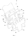
FIG. 1 is a structural view of a connection terminal according to example one of the present disclosure; -
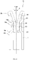
FIG. 2 is a front view of the connection terminal according to example one of the present disclosure; -
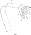
FIG. 3 is a structural view of a connection terminal according to example two of the present disclosure; -
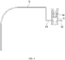
FIG. 4 is a front view of the connection terminal according to example two of the present disclosure; -
FIG. 5 is a structural view of a power supply device according to an example of the present disclosure; and -
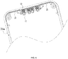
FIG. 6 is an enlarged view of a partial structure of the power supply device ofFIG. 5 . - Examples in accordance with the present disclosure are described in detail hereinafter. Examples of the examples are illustrated in the drawings, where the same or similar reference numerals indicate the same or similar elements or elements having the same or similar functions. The examples described hereinafter with reference to the drawings are merely exemplary. The examples are intended to explain the present disclosure and are not to be construed as limiting the present disclosure.
- In the description of the present disclosure, unless otherwise expressly specified and limited, the term "connected to each other", "connected" or "secured" is to be construed in a broad sense, for example, as securely connected, detachably connected or integrated; mechanically connected or electrically connected; directly connected to each other or indirectly connected to each other via an intermediary; or internally connected between two components or interaction relations between two components. For those of ordinary skill in the art, specific meanings of the preceding terms in the present disclosure may be understood based on specific situations.
- In the present disclosure, unless otherwise expressly specified and limited, when a first feature is described as "above" or "below" a second feature, the first feature and the second feature may be in direct contact or be in contact via another feature between the two features. Moreover, when the first feature is described as "on", "above", or "over" the second feature, the first feature is right on, above, or over the second feature or the first feature is obliquely on, above, or over the second feature, or the first feature is simply at a higher level than the second feature. When the first feature is described as "under", "below", or "underneath" the second feature, the first feature is right under, below, or underneath the second feature or the first feature is obliquely under, below, or underneath the second feature, or the first feature is simply at a lower level than the second feature.
- Technical solutions of the present disclosure are further described hereinafter in conjunction with the drawings and the examples.
- Referring to
FIGS. 1 to 2 , the example of the present disclosure provides aconnection terminal 10, and theconnection terminal 10 may be an electrode. Theconnection terminal 10 includes abody portion 11, asupport portion 12 and twoconnection pieces 13. The twoconnection pieces 13 are specifically a first connection piece 13a and a second connection piece 13b. Afirst end 11a of thebody portion 11 is disposed on a battery pack or a power tool, asecond end 11b of thebody portion 11 is connected to afirst end 12a of thesupport portion 12, and the two connection pieces 13a, 13b are disposed on asecond end 12b of thesupport portion 12 facing away from thebody portion 11. The two connection pieces 13a, 13b bend toward each other, aninner clamping space 135 is formed between the two connection pieces 13a, 13b for clamping anelectrode piece 40, and inner side surfaces 130 of the two connection pieces 13a, 13b are formed as planes to enable theelectrode piece 40 to be in surface contact with each of the two connection pieces 13a, 13b. Each of the inner side surfaces 130 comprises acontact surface 130a for connecting theelectrode piece 40, thecontact surface 130a is a plane extending along a first plane n so that the each of the two connection pieces 13a, 13b is in surface contact with theelectrode piece 40. - Since the connection pieces 13a, 13b are in surface contact with the
electrode piece 40, the contact area between theconnection terminal 10 and theelectrode piece 40 can be increased to reduce the contact resistance and thereby ameliorate the problem of heating of the battery pack or the power tool. At the same time, the poor contact caused by the contact force and vibration can be improved, so that the influence caused by the vibration can be further reduced and the connection can be more stable. - In the example, the
body portion 11 is formed in a U-shape, thesupport portion 12 is disposed on opposite sides of thebody portion 11, the connection pieces 13a, 13b are disposed on the end portion of thesupport portion 12, and the two connection pieces 13a, 13b bend toward each other. - The
body portion 11, thesupport portion 12 and the connection pieces 13a, 13b are integrally formed to facilitate processing and production and ensure the structural strength. The connection between thesupport portion 12 and eachconnection piece 13 bends in an arc shape, so that the connection pieces 13a, 13b have certain resilience. - The
support portion 12 includes amain body 122 andmultiple support arms 121, themultiple support arms 121 extends from themain body 122 to the connection pieces13a, 13b, somultiple support arms 121 abutouter side surfaces 134 of the connection pieces 13a, 13b. Theouter side surfaces 134 is opposite to the inner side surfaces 130. When theelectrode piece 40 is inserted into theinner clamping space 135, the inner side surfaces 130 of the connection pieces 13a, 13b abut theelectrode piece 40, and theouter side surfaces 134 of the connection pieces 13a, 13b abut thesupport arms 121, so that the inner sides and outer side surfaces of the connection pieces 13a, 13b are supported, and the plugging stability of theelectrode piece 40 is ensured. - Specifically, the
support arms 121 bend toward the connection pieces 13a, 13b relative to thesupport portion 12, so as to abut the connection pieces 13a, 13b. - Support
arms 121 on theouter side 134 of one of the two connection pieces 13a, 13b are arranged in the same form assupport arms 121 on theouter side 134 of the other one of the two connection pieces 13a, 13b, so that the clamping forces of the two connection pieces 13a, 13b to the electrode piece are consistent and uniform. - In the example, five
support arms 121 are provided for eachconnection piece 13, one of the fivesupport arms 121 abuts a middle part of the eachconnection piece 13, and four of the fivesupport arms 121 abut four corners of the eachconnection piece 13, so that eachconnection piece 13 is uniformly stressed as a whole. - Specifically, each
connection piece 13 includes aconnection portion 131 and acontact portion 132, theconnection portion 131 extends and bends relative to thecontact portion 132, theconnection portion 131 is connected to thesupport portion 12, and theinner clamping space 135 is formed between twocontact portions 132. The inner side of each of the twocontact portions 132 is provided thecontact surface 130a. Theconnection portion 131 serves as a transition so that the twocontact portions 132 can approach each other. Fivesupport arms 121 abut the outer side of thecontact portion 132. - A bell-
mouth structure 136 is formed between the twoconnection portions 131, and the bell-mouth structure 136 gradually increases along a direction away from theinner clamping space 135, so as to facilitate the insertion of theelectrode piece 40 into theinner clamping space 135. - A
notch 133 is provided at a junction of theconnection portion 131 and thesupport portion 12, and thenotch 133 extends toward the inner clamping space. Thenotch 133 is provided so that the resilience of the connection between the connection pieces 13a, 13b and thesupport portion 12 is enhanced and a certain space is provided for the deformation of the connection pieces 13a, 13b. - The
inner clamping space 135 is formed between thecontact surface 130a of the two connection pieces 13a, 13b, and the connection position between theconnection portion 131 and thecontact portion 132 is anentrance end 135a of theinner clamping space 135. If the inner side surfaces of the two connection pieces are parallel and thus the inner clamping space is rectangular, then when theelectrode piece 40 is inserted into the inner clamping space, the contact portion tends to tilt due to the leverage effect, resulting in that opening distances of two ends of the inner clamping space are different and the connection pieces cannot be in full contact with theelectrode piece 40. - In the example, the shape of the
inner clamping space 135 is an isosceles trapezoid, and along an insertion direction of theelectrode piece 40, theinner clamping space 135 gradually increases. - Specifically, the first connection piece 13a is symmetrical to the second connection piece 13b about a second plane m, an included angle between each of the
contact surface 130a of the two connection pieces 13a, 13b and the second plane m is a set angle, and thecontact surface 130a are gradually away from the second plane m along the insertion direction of theelectrode piece 40. Thecontact surface 130a is inclined to the second plane m. - In
FIG. 2 , the second plane is represented by m, the first plane n is an extended plane of thecontact surface 130a, and the included angle between the first plane n and the second plane m is represented by A. - When the
electrode piece 40 is inserted into theinner clamping space 135, theelectrode piece 40 first squeezes the connection position between theconnection portion 131 and thecontact portion 132. Since thecontact portion 132 is pre-tilted outward, the problem can be solved of the difference in the opening distances of the two ends of theinner clamping space 135 caused by the leverage effect, so that the connection pieces 13a, 13b can be in full contact with theelectrode piece 40 to ensure the insertion stability of theelectrode piece 40. - The angle of the included angle A may be set according to actual conditions and is not limited here. In the example, the included angle is about 1 degree.
-
FIGS. 3 and4 show another example, in which same or corresponding parts as in the preceding example are denoted by the corresponding reference numerals. For brevity, only the difference between the example and the preceding example is described below. The difference is that theconnection terminal 10 further includes aheat sink 21. Theheat sink 21 is connected to thebody portion 11 and extends toward a direction away from thesupport portion 12. Theheat sink 21 is provided so that the heat capacity of theconnection terminal 10 is increased, the contact area between theconnection terminal 10 and the air is also increased, and thereby the heat dissipation area is increased. Therefore, heat accumulation is avoided, so that the impact of a large current on the performance of the battery pack is reduced. - Specifically, one side of the
body portion 11 is provided with anextension portion 111, theextension portion 111 extends in the direction away from thesupport portion 12, and theheat sink 21 is connected to theextension portion 111 to adapt to the mounting space of theconnection terminal 10. - The shape of the
heat sink 21 may be set according to actual requirements. In the example, theheat sink 21 includes a straight portion and an arc-shaped portion, which increase the heat dissipation area of theheat sink 21 and also adapt to the mounting space of theheat sink 21. - Referring to
FIG. 5 , the example of the present disclosure further provides apower supply device 31, specifically providing a battery pack, which includes ahousing 31a and theconnection terminal 10 of any one of the preceding examples. - Referring to
FIGS. 5 to 6 , a mounting groove is provided in thehousing 31a of the battery pack, and theconnection terminal 10 is inserted into the mounting groove. A limit groove is provided in the housing, and theheat sink 21 is inserted into the limit groove. The limit groove is provided along the inner wall of thehousing 31a to reduce space occupation. - The preceding examples illustrate only the basic principles and features of the present disclosure. The present disclosure is not limited by the preceding examples. Various modifications and variations made without departing from the spirit and scope of the present disclosure fall within the scope of the present disclosure. The scope of the present disclosure is defined by the appended claims and their equivalents.
Claims (15)
- A connection terminal (10), comprising:a body portion (11) comprising a first end (11a) disposed on a power supply device (31) and a second end (11b) opposite to the first end;two connection pieces (13a, 13b), wherein an inner clamping space (135) for clamping a electrode piece (40) is formed between the two connection pieces; anda support portion (12) supporting the two connection pieces and disposed at the second end of the body portion;wherein the support portion connects the two connection pieces and the body portion,an inner side surface (130) of each of the two connection pieces comprises a contact surface (130a) for connecting with the electrode piece, and the contact surface extends along a first plane (n) so that the contact surface is capable of being in surface contact with the electrode piece.
- The connection terminal according to claim 1, wherein the support portion comprises at least one support arm (121), and the at least one support arm abuts outer side surfaces (134) of the two connection pieces.
- The connection terminal according to claim 1, wherein the support portion is formed with a plurality of support arms (121), and the plurality of support arms abut the outer side surfaces (134) of the two connection pieces so as to form a multi-point support for the two connection pieces.
- The connection terminal according to claim 2, wherein five support arms (121) are provided for each of the two connection pieces, one of the five support arms abuts a middle part of the each of the two connection pieces, and four of the five support arms abut four corners of the each of the two connection pieces.
- The connection terminal according to claim 1, wherein the two connection pieces are symmetrical about a second plane (m), and the contact surface is gradually away from the second plane along an insertion direction of the electrode piece.
- The connection terminal according to claim 1, wherein the two connection pieces are symmetrical about a second plane (m), and an included angle A between the first plane and the second plane is about 1 degree.
- The connection terminal according to claim 1, wherein each of the two connection pieces comprises a connection portion (131) and a contact portion (132), the connection portion extends and bends relative to the contact portion, the connection portion is connected to the support portion, the contact portion is provided with the contact surface, and the inner clamping space is formed between two contact surfaces.
- The connection terminal according to claim 7, wherein a bell-mouth structure (136) is formed between two connection portions and the bell-mouth structure gradually increases along a direction away from the inner clamping space.
- The connection terminal according to claim 7, wherein a notch (133) is provided at an intersection of the connection portion and the support portion, and the notch extends toward the inner clamping space.
- The connection terminal according to claim 1, wherein the body portion, the support portion and the two connection pieces are integrally formed.
- The connection terminal according to claim 1, further comprising a heat sink (21), wherein the heat sink is connected to the body portion and extends toward a direction away from the support portion.
- The connection terminal according to claim 1, wherein the support portion comprises a main body (122) connecting the body portion and the two connection pieces and a support arm (121) for abutting an outer side surface (134) of the two connection pieces.
- The connection terminal according to claim 12, wherein each of the two connection pieces comprises a connection portion (131) and a contact portion (132), the connection portion extends and bends relative to the contact portion, the connection portion is connected to the support portion, the contact portion is provided with the contact surface, the inner clamping space is formed between two contact surfaces, and the support arm abuts the contact portion.
- The connection terminal according to claim 13, wherein the support portion comprises plurality of support arms for abutting the contact portion.
- A power supply device (31), comprising a housing (31a) and a connection terminal (10),
wherein the connection terminal comprises:a body portion (11) comprising a first end (11a) disposed on the power supply device and a second end (11b) opposite to the first end;a first connection piece (13a) and a second connection piece (13b), an inner clamping space (135) for clamping a electrode piece (40) being formed between the first connection piece and the second connection piece; anda support portion (12) supporting the first connection piece and the second connection piece;wherein the inner side surface (130) of the first connection piece comprises a first contact surface (130a) for connecting with the electrode piece, the inner side surface of the second connection piece comprises a second contact surface for connecting with the electrode piece, and the first contact surface extends along a first plane (n) so that the first contact surface is capable of being in surface contact with the electrode piece.
Applications Claiming Priority (1)
| Application Number | Priority Date | Filing Date | Title |
|---|---|---|---|
| CN202110048687.6A CN114765319A (en) | 2021-01-14 | 2021-01-14 | Electrode and battery pack |
Publications (2)
| Publication Number | Publication Date |
|---|---|
| EP4030564A1 true EP4030564A1 (en) | 2022-07-20 |
| EP4030564B1 EP4030564B1 (en) | 2023-05-31 |
Family
ID=79283078
Family Applications (1)
| Application Number | Title | Priority Date | Filing Date |
|---|---|---|---|
| EP22150496.2A Active EP4030564B1 (en) | 2021-01-14 | 2022-01-07 | Connection terminal and power supply device |
Country Status (3)
| Country | Link |
|---|---|
| US (1) | US11824297B2 (en) |
| EP (1) | EP4030564B1 (en) |
| CN (1) | CN114765319A (en) |
Families Citing this family (1)
| Publication number | Priority date | Publication date | Assignee | Title |
|---|---|---|---|---|
| US20220368052A1 (en) * | 2021-05-12 | 2022-11-17 | Aptiv Technologies Limited | High voltage (hv) terminal frame |
Citations (4)
| Publication number | Priority date | Publication date | Assignee | Title |
|---|---|---|---|---|
| US3076953A (en) * | 1959-03-13 | 1963-02-05 | Clifford E Sloop | Spacer for spring-jaw type spade terminal |
| FR2565423A1 (en) * | 1984-05-29 | 1985-12-06 | Essex Group | RECEPTACLE TERMINAL WITH LEGS |
| GB2314468A (en) * | 1996-06-21 | 1997-12-24 | Mecanismos Aux Ind | Female terminal for a printed circuit board |
| EP2448066A1 (en) * | 2010-10-27 | 2012-05-02 | Sumitomo Wiring Systems, Ltd. | Terminal containing section for an electrical junction box and electrical junction box therewith |
Family Cites Families (20)
| Publication number | Priority date | Publication date | Assignee | Title |
|---|---|---|---|---|
| US3152857A (en) * | 1962-03-05 | 1964-10-13 | B & C Metal Stamping Company | Terminal for electrical meter socket |
| US4472017A (en) * | 1983-04-01 | 1984-09-18 | Essex Group, Inc. | Tab receptacle terminal |
| JPS6048678U (en) * | 1983-09-09 | 1985-04-05 | アンプ インコ−ポレ−テツド | electrical connectors |
| DE3826670C2 (en) * | 1988-08-05 | 1994-11-17 | Framatome Connectors Int | Flat contact socket |
| EP1215763B2 (en) * | 2000-10-12 | 2007-12-05 | Tyco Electronics AMP GmbH | Female contact for an electrical connector |
| US6561828B2 (en) * | 2001-10-10 | 2003-05-13 | Brokelmann, Jaeger & Busse, Gmbh & Co. | Fluorescent-lamp socket |
| FR2844104A1 (en) * | 2002-08-27 | 2004-03-05 | Framatome Connectors Int | CONTACT TERMINAL WITH ELASTIC CONTACT BLADE |
| EP2048746B1 (en) * | 2007-08-13 | 2016-10-05 | Tyco Electronics Nederland B.V. | Busbar connection system |
| CN201829675U (en) * | 2010-09-23 | 2011-05-11 | 富士康(昆山)电脑接插件有限公司 | Conductive terminal |
| US8388389B2 (en) * | 2011-07-07 | 2013-03-05 | Tyco Electronics Corporation | Electrical connectors having opposing electrical contacts |
| US8986030B2 (en) * | 2012-12-06 | 2015-03-24 | Phoenix Contact Development and Manufacturing, Inc. | Modular electric power distribution system |
| US9680236B2 (en) * | 2013-07-08 | 2017-06-13 | Fci Americas Technology Llc | Electrical connector |
| JP2015037030A (en) * | 2013-08-12 | 2015-02-23 | 日本圧着端子製造株式会社 | Jack |
| CN105830284B (en) * | 2013-12-06 | 2020-09-15 | 安费诺富加宜(亚洲)私人有限公司 | Cable Assemblies for Power Connections |
| JP6437276B2 (en) * | 2014-11-04 | 2018-12-12 | 日本航空電子工業株式会社 | connector |
| CN204376023U (en) * | 2015-01-29 | 2015-06-03 | 欧品电子(昆山)有限公司 | Copper bar connector and terminal assemblies |
| BR102016028101B1 (en) * | 2015-12-03 | 2023-04-04 | Linde Aktiengesellschaft | FEMALE CONTACT ELEMENT FOR A SLIPPING RING MOTOR AND SLIPPING RING MOTOR |
| CN109510015B (en) * | 2017-09-15 | 2020-11-06 | 泰科电子(上海)有限公司 | Power Connectors and Connector Assemblies |
| US10879647B2 (en) * | 2018-03-16 | 2020-12-29 | Fci Usa Llc | Double pole power connector |
| CN113823934B (en) * | 2020-06-19 | 2025-06-17 | 泰科电子(上海)有限公司 | Connectors and conductive terminal modules |
-
2021
- 2021-01-14 CN CN202110048687.6A patent/CN114765319A/en active Pending
-
2022
- 2022-01-07 US US17/571,001 patent/US11824297B2/en active Active
- 2022-01-07 EP EP22150496.2A patent/EP4030564B1/en active Active
Patent Citations (4)
| Publication number | Priority date | Publication date | Assignee | Title |
|---|---|---|---|---|
| US3076953A (en) * | 1959-03-13 | 1963-02-05 | Clifford E Sloop | Spacer for spring-jaw type spade terminal |
| FR2565423A1 (en) * | 1984-05-29 | 1985-12-06 | Essex Group | RECEPTACLE TERMINAL WITH LEGS |
| GB2314468A (en) * | 1996-06-21 | 1997-12-24 | Mecanismos Aux Ind | Female terminal for a printed circuit board |
| EP2448066A1 (en) * | 2010-10-27 | 2012-05-02 | Sumitomo Wiring Systems, Ltd. | Terminal containing section for an electrical junction box and electrical junction box therewith |
Also Published As
| Publication number | Publication date |
|---|---|
| CN114765319A (en) | 2022-07-19 |
| EP4030564B1 (en) | 2023-05-31 |
| US11824297B2 (en) | 2023-11-21 |
| US20220224036A1 (en) | 2022-07-14 |
Similar Documents
| Publication | Publication Date | Title |
|---|---|---|
| US9525254B2 (en) | Electrical power connector and a terminal assembly | |
| CN206180228U (en) | Power connector and its power terminals | |
| US20180331442A1 (en) | Electrical connector | |
| US20160226177A1 (en) | Electrical power connector and a terminal assembly | |
| US10658775B2 (en) | Electrical connector directly connecting an electronic component to a circuit board | |
| TW201733217A (en) | Electrical connector and contact thereof | |
| TW547801U (en) | Electrical connector | |
| CN110098518A (en) | A kind of stable type female terminal and its stable type the male and female insertions electric connector of application | |
| EP4030564A1 (en) | Connection terminal and power supply device | |
| CN112018541A (en) | Connector for high-current terminal | |
| US9531102B2 (en) | Electrical power connector and a terminal assembly | |
| CN106856266A (en) | Power supply connector | |
| CN201038388Y (en) | Power supply connector | |
| CN209766702U (en) | Connector for high-current terminal | |
| TW202143566A (en) | Conductive terminal | |
| CN208923460U (en) | A kind of wire connection terminal | |
| CN110459888B (en) | Connecting components and conductive terminals thereof | |
| CN209389260U (en) | power connector | |
| TWM628619U (en) | Electrical connector | |
| CN222282309U (en) | Socket and power adapter | |
| CN219017935U (en) | Signal terminal | |
| CN221885418U (en) | Connector and electronic equipment | |
| CN218827931U (en) | Signal terminal | |
| CN222785531U (en) | Chip jack structure | |
| CN223624918U (en) | A three-dimensional four-sided connected patch fuse holder |
Legal Events
| Date | Code | Title | Description |
|---|---|---|---|
| PUAI | Public reference made under article 153(3) epc to a published international application that has entered the european phase |
Free format text: ORIGINAL CODE: 0009012 |
|
| STAA | Information on the status of an ep patent application or granted ep patent |
Free format text: STATUS: THE APPLICATION HAS BEEN PUBLISHED |
|
| AK | Designated contracting states |
Kind code of ref document: A1 Designated state(s): AL AT BE BG CH CY CZ DE DK EE ES FI FR GB GR HR HU IE IS IT LI LT LU LV MC MK MT NL NO PL PT RO RS SE SI SK SM TR |
|
| STAA | Information on the status of an ep patent application or granted ep patent |
Free format text: STATUS: REQUEST FOR EXAMINATION WAS MADE |
|
| 17P | Request for examination filed |
Effective date: 20221228 |
|
| RBV | Designated contracting states (corrected) |
Designated state(s): AL AT BE BG CH CY CZ DE DK EE ES FI FR GB GR HR HU IE IS IT LI LT LU LV MC MK MT NL NO PL PT RO RS SE SI SK SM TR |
|
| GRAP | Despatch of communication of intention to grant a patent |
Free format text: ORIGINAL CODE: EPIDOSNIGR1 |
|
| STAA | Information on the status of an ep patent application or granted ep patent |
Free format text: STATUS: GRANT OF PATENT IS INTENDED |
|
| RIC1 | Information provided on ipc code assigned before grant |
Ipc: H01R 13/18 20060101ALN20230309BHEP Ipc: H01R 13/11 20060101AFI20230309BHEP |
|
| GRAS | Grant fee paid |
Free format text: ORIGINAL CODE: EPIDOSNIGR3 |
|
| GRAA | (expected) grant |
Free format text: ORIGINAL CODE: 0009210 |
|
| STAA | Information on the status of an ep patent application or granted ep patent |
Free format text: STATUS: THE PATENT HAS BEEN GRANTED |
|
| INTG | Intention to grant announced |
Effective date: 20230403 |
|
| AK | Designated contracting states |
Kind code of ref document: B1 Designated state(s): AL AT BE BG CH CY CZ DE DK EE ES FI FR GB GR HR HU IE IS IT LI LT LU LV MC MK MT NL NO PL PT RO RS SE SI SK SM TR |
|
| REG | Reference to a national code |
Ref country code: GB Ref legal event code: FG4D Ref country code: CH Ref legal event code: EP |
|
| REG | Reference to a national code |
Ref country code: AT Ref legal event code: REF Ref document number: 1571529 Country of ref document: AT Kind code of ref document: T Effective date: 20230615 Ref country code: DE Ref legal event code: R096 Ref document number: 602022000090 Country of ref document: DE |
|
| REG | Reference to a national code |
Ref country code: IE Ref legal event code: FG4D |
|
| REG | Reference to a national code |
Ref country code: LT Ref legal event code: MG9D |
|
| REG | Reference to a national code |
Ref country code: NL Ref legal event code: MP Effective date: 20230531 |
|
| REG | Reference to a national code |
Ref country code: AT Ref legal event code: MK05 Ref document number: 1571529 Country of ref document: AT Kind code of ref document: T Effective date: 20230531 |
|
| PG25 | Lapsed in a contracting state [announced via postgrant information from national office to epo] |
Ref country code: SE Free format text: LAPSE BECAUSE OF FAILURE TO SUBMIT A TRANSLATION OF THE DESCRIPTION OR TO PAY THE FEE WITHIN THE PRESCRIBED TIME-LIMIT Effective date: 20230531 Ref country code: NO Free format text: LAPSE BECAUSE OF FAILURE TO SUBMIT A TRANSLATION OF THE DESCRIPTION OR TO PAY THE FEE WITHIN THE PRESCRIBED TIME-LIMIT Effective date: 20230831 Ref country code: ES Free format text: LAPSE BECAUSE OF FAILURE TO SUBMIT A TRANSLATION OF THE DESCRIPTION OR TO PAY THE FEE WITHIN THE PRESCRIBED TIME-LIMIT Effective date: 20230531 Ref country code: AT Free format text: LAPSE BECAUSE OF FAILURE TO SUBMIT A TRANSLATION OF THE DESCRIPTION OR TO PAY THE FEE WITHIN THE PRESCRIBED TIME-LIMIT Effective date: 20230531 |
|
| PG25 | Lapsed in a contracting state [announced via postgrant information from national office to epo] |
Ref country code: RS Free format text: LAPSE BECAUSE OF FAILURE TO SUBMIT A TRANSLATION OF THE DESCRIPTION OR TO PAY THE FEE WITHIN THE PRESCRIBED TIME-LIMIT Effective date: 20230531 Ref country code: PL Free format text: LAPSE BECAUSE OF FAILURE TO SUBMIT A TRANSLATION OF THE DESCRIPTION OR TO PAY THE FEE WITHIN THE PRESCRIBED TIME-LIMIT Effective date: 20230531 Ref country code: NL Free format text: LAPSE BECAUSE OF FAILURE TO SUBMIT A TRANSLATION OF THE DESCRIPTION OR TO PAY THE FEE WITHIN THE PRESCRIBED TIME-LIMIT Effective date: 20230531 Ref country code: LV Free format text: LAPSE BECAUSE OF FAILURE TO SUBMIT A TRANSLATION OF THE DESCRIPTION OR TO PAY THE FEE WITHIN THE PRESCRIBED TIME-LIMIT Effective date: 20230531 Ref country code: LT Free format text: LAPSE BECAUSE OF FAILURE TO SUBMIT A TRANSLATION OF THE DESCRIPTION OR TO PAY THE FEE WITHIN THE PRESCRIBED TIME-LIMIT Effective date: 20230531 Ref country code: IS Free format text: LAPSE BECAUSE OF FAILURE TO SUBMIT A TRANSLATION OF THE DESCRIPTION OR TO PAY THE FEE WITHIN THE PRESCRIBED TIME-LIMIT Effective date: 20230930 Ref country code: HR Free format text: LAPSE BECAUSE OF FAILURE TO SUBMIT A TRANSLATION OF THE DESCRIPTION OR TO PAY THE FEE WITHIN THE PRESCRIBED TIME-LIMIT Effective date: 20230531 Ref country code: GR Free format text: LAPSE BECAUSE OF FAILURE TO SUBMIT A TRANSLATION OF THE DESCRIPTION OR TO PAY THE FEE WITHIN THE PRESCRIBED TIME-LIMIT Effective date: 20230901 |
|
| PG25 | Lapsed in a contracting state [announced via postgrant information from national office to epo] |
Ref country code: FI Free format text: LAPSE BECAUSE OF FAILURE TO SUBMIT A TRANSLATION OF THE DESCRIPTION OR TO PAY THE FEE WITHIN THE PRESCRIBED TIME-LIMIT Effective date: 20230531 |
|
| PG25 | Lapsed in a contracting state [announced via postgrant information from national office to epo] |
Ref country code: SK Free format text: LAPSE BECAUSE OF FAILURE TO SUBMIT A TRANSLATION OF THE DESCRIPTION OR TO PAY THE FEE WITHIN THE PRESCRIBED TIME-LIMIT Effective date: 20230531 |
|
| PG25 | Lapsed in a contracting state [announced via postgrant information from national office to epo] |
Ref country code: SM Free format text: LAPSE BECAUSE OF FAILURE TO SUBMIT A TRANSLATION OF THE DESCRIPTION OR TO PAY THE FEE WITHIN THE PRESCRIBED TIME-LIMIT Effective date: 20230531 Ref country code: SK Free format text: LAPSE BECAUSE OF FAILURE TO SUBMIT A TRANSLATION OF THE DESCRIPTION OR TO PAY THE FEE WITHIN THE PRESCRIBED TIME-LIMIT Effective date: 20230531 Ref country code: RO Free format text: LAPSE BECAUSE OF FAILURE TO SUBMIT A TRANSLATION OF THE DESCRIPTION OR TO PAY THE FEE WITHIN THE PRESCRIBED TIME-LIMIT Effective date: 20230531 Ref country code: PT Free format text: LAPSE BECAUSE OF FAILURE TO SUBMIT A TRANSLATION OF THE DESCRIPTION OR TO PAY THE FEE WITHIN THE PRESCRIBED TIME-LIMIT Effective date: 20231002 Ref country code: EE Free format text: LAPSE BECAUSE OF FAILURE TO SUBMIT A TRANSLATION OF THE DESCRIPTION OR TO PAY THE FEE WITHIN THE PRESCRIBED TIME-LIMIT Effective date: 20230531 Ref country code: DK Free format text: LAPSE BECAUSE OF FAILURE TO SUBMIT A TRANSLATION OF THE DESCRIPTION OR TO PAY THE FEE WITHIN THE PRESCRIBED TIME-LIMIT Effective date: 20230531 Ref country code: CZ Free format text: LAPSE BECAUSE OF FAILURE TO SUBMIT A TRANSLATION OF THE DESCRIPTION OR TO PAY THE FEE WITHIN THE PRESCRIBED TIME-LIMIT Effective date: 20230531 |
|
| PGFP | Annual fee paid to national office [announced via postgrant information from national office to epo] |
Ref country code: FR Payment date: 20231108 Year of fee payment: 3 |
|
| REG | Reference to a national code |
Ref country code: DE Ref legal event code: R097 Ref document number: 602022000090 Country of ref document: DE |
|
| PLBE | No opposition filed within time limit |
Free format text: ORIGINAL CODE: 0009261 |
|
| STAA | Information on the status of an ep patent application or granted ep patent |
Free format text: STATUS: NO OPPOSITION FILED WITHIN TIME LIMIT |
|
| PGFP | Annual fee paid to national office [announced via postgrant information from national office to epo] |
Ref country code: DE Payment date: 20231114 Year of fee payment: 3 |
|
| PG25 | Lapsed in a contracting state [announced via postgrant information from national office to epo] |
Ref country code: SI Free format text: LAPSE BECAUSE OF FAILURE TO SUBMIT A TRANSLATION OF THE DESCRIPTION OR TO PAY THE FEE WITHIN THE PRESCRIBED TIME-LIMIT Effective date: 20230531 |
|
| 26N | No opposition filed |
Effective date: 20240301 |
|
| PG25 | Lapsed in a contracting state [announced via postgrant information from national office to epo] |
Ref country code: SI Free format text: LAPSE BECAUSE OF FAILURE TO SUBMIT A TRANSLATION OF THE DESCRIPTION OR TO PAY THE FEE WITHIN THE PRESCRIBED TIME-LIMIT Effective date: 20230531 Ref country code: IT Free format text: LAPSE BECAUSE OF FAILURE TO SUBMIT A TRANSLATION OF THE DESCRIPTION OR TO PAY THE FEE WITHIN THE PRESCRIBED TIME-LIMIT Effective date: 20230531 |
|
| PG25 | Lapsed in a contracting state [announced via postgrant information from national office to epo] |
Ref country code: MC Free format text: LAPSE BECAUSE OF FAILURE TO SUBMIT A TRANSLATION OF THE DESCRIPTION OR TO PAY THE FEE WITHIN THE PRESCRIBED TIME-LIMIT Effective date: 20230531 |
|
| PG25 | Lapsed in a contracting state [announced via postgrant information from national office to epo] |
Ref country code: MC Free format text: LAPSE BECAUSE OF FAILURE TO SUBMIT A TRANSLATION OF THE DESCRIPTION OR TO PAY THE FEE WITHIN THE PRESCRIBED TIME-LIMIT Effective date: 20230531 |
|
| PG25 | Lapsed in a contracting state [announced via postgrant information from national office to epo] |
Ref country code: LU Free format text: LAPSE BECAUSE OF NON-PAYMENT OF DUE FEES Effective date: 20240107 |
|
| PG25 | Lapsed in a contracting state [announced via postgrant information from national office to epo] |
Ref country code: LU Free format text: LAPSE BECAUSE OF NON-PAYMENT OF DUE FEES Effective date: 20240107 |
|
| PG25 | Lapsed in a contracting state [announced via postgrant information from national office to epo] |
Ref country code: BE Free format text: LAPSE BECAUSE OF NON-PAYMENT OF DUE FEES Effective date: 20240131 |
|
| PG25 | Lapsed in a contracting state [announced via postgrant information from national office to epo] |
Ref country code: BE Free format text: LAPSE BECAUSE OF NON-PAYMENT OF DUE FEES Effective date: 20240131 |
|
| REG | Reference to a national code |
Ref country code: BE Ref legal event code: MM Effective date: 20240131 |
|
| PG25 | Lapsed in a contracting state [announced via postgrant information from national office to epo] |
Ref country code: BG Free format text: LAPSE BECAUSE OF FAILURE TO SUBMIT A TRANSLATION OF THE DESCRIPTION OR TO PAY THE FEE WITHIN THE PRESCRIBED TIME-LIMIT Effective date: 20230531 |
|
| PG25 | Lapsed in a contracting state [announced via postgrant information from national office to epo] |
Ref country code: BG Free format text: LAPSE BECAUSE OF FAILURE TO SUBMIT A TRANSLATION OF THE DESCRIPTION OR TO PAY THE FEE WITHIN THE PRESCRIBED TIME-LIMIT Effective date: 20230531 |
|
| PG25 | Lapsed in a contracting state [announced via postgrant information from national office to epo] |
Ref country code: IE Free format text: LAPSE BECAUSE OF NON-PAYMENT OF DUE FEES Effective date: 20240107 |
|
| PG25 | Lapsed in a contracting state [announced via postgrant information from national office to epo] |
Ref country code: IE Free format text: LAPSE BECAUSE OF NON-PAYMENT OF DUE FEES Effective date: 20240107 |
|
| REG | Reference to a national code |
Ref country code: DE Ref legal event code: R119 Ref document number: 602022000090 Country of ref document: DE |
|
| PG25 | Lapsed in a contracting state [announced via postgrant information from national office to epo] |
Ref country code: CY Free format text: LAPSE BECAUSE OF FAILURE TO SUBMIT A TRANSLATION OF THE DESCRIPTION OR TO PAY THE FEE WITHIN THE PRESCRIBED TIME-LIMIT; INVALID AB INITIO Effective date: 20220107 |
|
| REG | Reference to a national code |
Ref country code: CH Ref legal event code: PL |
|
| PG25 | Lapsed in a contracting state [announced via postgrant information from national office to epo] |
Ref country code: DE Free format text: LAPSE BECAUSE OF NON-PAYMENT OF DUE FEES Effective date: 20250801 |
|
| PG25 | Lapsed in a contracting state [announced via postgrant information from national office to epo] |
Ref country code: FR Free format text: LAPSE BECAUSE OF NON-PAYMENT OF DUE FEES Effective date: 20250131 |
|
| PG25 | Lapsed in a contracting state [announced via postgrant information from national office to epo] |
Ref country code: CH Free format text: LAPSE BECAUSE OF NON-PAYMENT OF DUE FEES Effective date: 20250131 |
|
| PG25 | Lapsed in a contracting state [announced via postgrant information from national office to epo] |
Ref country code: TR Free format text: LAPSE BECAUSE OF FAILURE TO SUBMIT A TRANSLATION OF THE DESCRIPTION OR TO PAY THE FEE WITHIN THE PRESCRIBED TIME-LIMIT Effective date: 20230531 |