EP4030562A1 - Glass mounted electronic assembly - Google Patents
Glass mounted electronic assembly Download PDFInfo
- Publication number
- EP4030562A1 EP4030562A1 EP22151347.6A EP22151347A EP4030562A1 EP 4030562 A1 EP4030562 A1 EP 4030562A1 EP 22151347 A EP22151347 A EP 22151347A EP 4030562 A1 EP4030562 A1 EP 4030562A1
- Authority
- EP
- European Patent Office
- Prior art keywords
- electronic assembly
- electrical terminals
- glass surface
- disposed
- flexible electrical
- Prior art date
- Legal status (The legal status is an assumption and is not a legal conclusion. Google has not performed a legal analysis and makes no representation as to the accuracy of the status listed.)
- Granted
Links
Images


Classifications
-
- H—ELECTRICITY
- H01—ELECTRIC ELEMENTS
- H01R—ELECTRICALLY-CONDUCTIVE CONNECTIONS; STRUCTURAL ASSOCIATIONS OF A PLURALITY OF MUTUALLY-INSULATED ELECTRICAL CONNECTING ELEMENTS; COUPLING DEVICES; CURRENT COLLECTORS
- H01R24/00—Two-part coupling devices, or either of their cooperating parts, characterised by their overall structure
- H01R24/38—Two-part coupling devices, or either of their cooperating parts, characterised by their overall structure having concentrically or coaxially arranged contacts
- H01R24/40—Two-part coupling devices, or either of their cooperating parts, characterised by their overall structure having concentrically or coaxially arranged contacts specially adapted for high frequency
-
- H—ELECTRICITY
- H01—ELECTRIC ELEMENTS
- H01R—ELECTRICALLY-CONDUCTIVE CONNECTIONS; STRUCTURAL ASSOCIATIONS OF A PLURALITY OF MUTUALLY-INSULATED ELECTRICAL CONNECTING ELEMENTS; COUPLING DEVICES; CURRENT COLLECTORS
- H01R24/00—Two-part coupling devices, or either of their cooperating parts, characterised by their overall structure
- H01R24/38—Two-part coupling devices, or either of their cooperating parts, characterised by their overall structure having concentrically or coaxially arranged contacts
- H01R24/40—Two-part coupling devices, or either of their cooperating parts, characterised by their overall structure having concentrically or coaxially arranged contacts specially adapted for high frequency
- H01R24/50—Two-part coupling devices, or either of their cooperating parts, characterised by their overall structure having concentrically or coaxially arranged contacts specially adapted for high frequency mounted on a PCB [Printed Circuit Board]
-
- H—ELECTRICITY
- H01—ELECTRIC ELEMENTS
- H01Q—ANTENNAS, i.e. RADIO AERIALS
- H01Q1/00—Details of, or arrangements associated with, antennas
- H01Q1/12—Supports; Mounting means
- H01Q1/1271—Supports; Mounting means for mounting on windscreens
-
- H—ELECTRICITY
- H01—ELECTRIC ELEMENTS
- H01Q—ANTENNAS, i.e. RADIO AERIALS
- H01Q1/00—Details of, or arrangements associated with, antennas
- H01Q1/12—Supports; Mounting means
- H01Q1/22—Supports; Mounting means by structural association with other equipment or articles
- H01Q1/24—Supports; Mounting means by structural association with other equipment or articles with receiving set
-
- H—ELECTRICITY
- H01—ELECTRIC ELEMENTS
- H01Q—ANTENNAS, i.e. RADIO AERIALS
- H01Q1/00—Details of, or arrangements associated with, antennas
- H01Q1/36—Structural form of radiating elements, e.g. cone, spiral, umbrella; Particular materials used therewith
- H01Q1/38—Structural form of radiating elements, e.g. cone, spiral, umbrella; Particular materials used therewith formed by a conductive layer on an insulating support
-
- H—ELECTRICITY
- H01—ELECTRIC ELEMENTS
- H01Q—ANTENNAS, i.e. RADIO AERIALS
- H01Q1/00—Details of, or arrangements associated with, antennas
- H01Q1/50—Structural association of antennas with earthing switches, lead-in devices or lightning protectors
-
- H—ELECTRICITY
- H01—ELECTRIC ELEMENTS
- H01R—ELECTRICALLY-CONDUCTIVE CONNECTIONS; STRUCTURAL ASSOCIATIONS OF A PLURALITY OF MUTUALLY-INSULATED ELECTRICAL CONNECTING ELEMENTS; COUPLING DEVICES; CURRENT COLLECTORS
- H01R12/00—Structural associations of a plurality of mutually-insulated electrical connecting elements, specially adapted for printed circuits, e.g. printed circuit boards [PCB], flat or ribbon cables, or like generally planar structures, e.g. terminal strips, terminal blocks; Coupling devices specially adapted for printed circuits, flat or ribbon cables, or like generally planar structures; Terminals specially adapted for contact with, or insertion into, printed circuits, flat or ribbon cables, or like generally planar structures
- H01R12/50—Fixed connections
- H01R12/51—Fixed connections for rigid printed circuits or like structures
- H01R12/55—Fixed connections for rigid printed circuits or like structures characterised by the terminals
- H01R12/57—Fixed connections for rigid printed circuits or like structures characterised by the terminals surface mounting terminals
-
- H—ELECTRICITY
- H01—ELECTRIC ELEMENTS
- H01R—ELECTRICALLY-CONDUCTIVE CONNECTIONS; STRUCTURAL ASSOCIATIONS OF A PLURALITY OF MUTUALLY-INSULATED ELECTRICAL CONNECTING ELEMENTS; COUPLING DEVICES; CURRENT COLLECTORS
- H01R12/00—Structural associations of a plurality of mutually-insulated electrical connecting elements, specially adapted for printed circuits, e.g. printed circuit boards [PCB], flat or ribbon cables, or like generally planar structures, e.g. terminal strips, terminal blocks; Coupling devices specially adapted for printed circuits, flat or ribbon cables, or like generally planar structures; Terminals specially adapted for contact with, or insertion into, printed circuits, flat or ribbon cables, or like generally planar structures
- H01R12/70—Coupling devices
- H01R12/91—Coupling devices allowing relative movement between coupling parts, e.g. floating or self aligning
-
- H—ELECTRICITY
- H01—ELECTRIC ELEMENTS
- H01R—ELECTRICALLY-CONDUCTIVE CONNECTIONS; STRUCTURAL ASSOCIATIONS OF A PLURALITY OF MUTUALLY-INSULATED ELECTRICAL CONNECTING ELEMENTS; COUPLING DEVICES; CURRENT COLLECTORS
- H01R13/00—Details of coupling devices of the kinds covered by groups H01R12/70 or H01R24/00 - H01R33/00
- H01R13/66—Structural association with built-in electrical component
- H01R13/665—Structural association with built-in electrical component with built-in electronic circuit
- H01R13/6658—Structural association with built-in electrical component with built-in electronic circuit on printed circuit board
-
- H—ELECTRICITY
- H01—ELECTRIC ELEMENTS
- H01R—ELECTRICALLY-CONDUCTIVE CONNECTIONS; STRUCTURAL ASSOCIATIONS OF A PLURALITY OF MUTUALLY-INSULATED ELECTRICAL CONNECTING ELEMENTS; COUPLING DEVICES; CURRENT COLLECTORS
- H01R13/00—Details of coupling devices of the kinds covered by groups H01R12/70 or H01R24/00 - H01R33/00
- H01R13/73—Means for mounting coupling parts to apparatus or structures, e.g. to a wall
-
- H—ELECTRICITY
- H01—ELECTRIC ELEMENTS
- H01R—ELECTRICALLY-CONDUCTIVE CONNECTIONS; STRUCTURAL ASSOCIATIONS OF A PLURALITY OF MUTUALLY-INSULATED ELECTRICAL CONNECTING ELEMENTS; COUPLING DEVICES; CURRENT COLLECTORS
- H01R43/00—Apparatus or processes specially adapted for manufacturing, assembling, maintaining, or repairing of line connectors or current collectors or for joining electric conductors
- H01R43/20—Apparatus or processes specially adapted for manufacturing, assembling, maintaining, or repairing of line connectors or current collectors or for joining electric conductors for assembling or disassembling contact members with insulating base, case or sleeve
- H01R43/205—Apparatus or processes specially adapted for manufacturing, assembling, maintaining, or repairing of line connectors or current collectors or for joining electric conductors for assembling or disassembling contact members with insulating base, case or sleeve with a panel or printed circuit board
-
- H—ELECTRICITY
- H05—ELECTRIC TECHNIQUES NOT OTHERWISE PROVIDED FOR
- H05K—PRINTED CIRCUITS; CASINGS OR CONSTRUCTIONAL DETAILS OF ELECTRIC APPARATUS; MANUFACTURE OF ASSEMBLAGES OF ELECTRICAL COMPONENTS
- H05K1/00—Printed circuits
- H05K1/02—Details
- H05K1/14—Structural association of two or more printed circuits
- H05K1/147—Structural association of two or more printed circuits at least one of the printed circuits being bent or folded, e.g. by using a flexible printed circuit
-
- H—ELECTRICITY
- H05—ELECTRIC TECHNIQUES NOT OTHERWISE PROVIDED FOR
- H05K—PRINTED CIRCUITS; CASINGS OR CONSTRUCTIONAL DETAILS OF ELECTRIC APPARATUS; MANUFACTURE OF ASSEMBLAGES OF ELECTRICAL COMPONENTS
- H05K1/00—Printed circuits
- H05K1/18—Printed circuits structurally associated with non-printed electric components
-
- H—ELECTRICITY
- H05—ELECTRIC TECHNIQUES NOT OTHERWISE PROVIDED FOR
- H05K—PRINTED CIRCUITS; CASINGS OR CONSTRUCTIONAL DETAILS OF ELECTRIC APPARATUS; MANUFACTURE OF ASSEMBLAGES OF ELECTRICAL COMPONENTS
- H05K5/00—Casings, cabinets or drawers for electric apparatus
- H05K5/0026—Casings, cabinets or drawers for electric apparatus provided with connectors and printed circuit boards [PCB], e.g. automotive electronic control units
- H05K5/0034—Casings, cabinets or drawers for electric apparatus provided with connectors and printed circuit boards [PCB], e.g. automotive electronic control units having an overmolded housing covering the PCB
-
- H—ELECTRICITY
- H05—ELECTRIC TECHNIQUES NOT OTHERWISE PROVIDED FOR
- H05K—PRINTED CIRCUITS; CASINGS OR CONSTRUCTIONAL DETAILS OF ELECTRIC APPARATUS; MANUFACTURE OF ASSEMBLAGES OF ELECTRICAL COMPONENTS
- H05K5/00—Casings, cabinets or drawers for electric apparatus
- H05K5/0026—Casings, cabinets or drawers for electric apparatus provided with connectors and printed circuit boards [PCB], e.g. automotive electronic control units
- H05K5/0069—Casings, cabinets or drawers for electric apparatus provided with connectors and printed circuit boards [PCB], e.g. automotive electronic control units having connector relating features for connecting the connector pins with the PCB or for mounting the connector body with the housing
-
- H—ELECTRICITY
- H01—ELECTRIC ELEMENTS
- H01R—ELECTRICALLY-CONDUCTIVE CONNECTIONS; STRUCTURAL ASSOCIATIONS OF A PLURALITY OF MUTUALLY-INSULATED ELECTRICAL CONNECTING ELEMENTS; COUPLING DEVICES; CURRENT COLLECTORS
- H01R12/00—Structural associations of a plurality of mutually-insulated electrical connecting elements, specially adapted for printed circuits, e.g. printed circuit boards [PCB], flat or ribbon cables, or like generally planar structures, e.g. terminal strips, terminal blocks; Coupling devices specially adapted for printed circuits, flat or ribbon cables, or like generally planar structures; Terminals specially adapted for contact with, or insertion into, printed circuits, flat or ribbon cables, or like generally planar structures
- H01R12/50—Fixed connections
- H01R12/51—Fixed connections for rigid printed circuits or like structures
- H01R12/52—Fixed connections for rigid printed circuits or like structures connecting to other rigid printed circuits or like structures
-
- H—ELECTRICITY
- H01—ELECTRIC ELEMENTS
- H01R—ELECTRICALLY-CONDUCTIVE CONNECTIONS; STRUCTURAL ASSOCIATIONS OF A PLURALITY OF MUTUALLY-INSULATED ELECTRICAL CONNECTING ELEMENTS; COUPLING DEVICES; CURRENT COLLECTORS
- H01R12/00—Structural associations of a plurality of mutually-insulated electrical connecting elements, specially adapted for printed circuits, e.g. printed circuit boards [PCB], flat or ribbon cables, or like generally planar structures, e.g. terminal strips, terminal blocks; Coupling devices specially adapted for printed circuits, flat or ribbon cables, or like generally planar structures; Terminals specially adapted for contact with, or insertion into, printed circuits, flat or ribbon cables, or like generally planar structures
- H01R12/50—Fixed connections
- H01R12/51—Fixed connections for rigid printed circuits or like structures
- H01R12/55—Fixed connections for rigid printed circuits or like structures characterised by the terminals
-
- H—ELECTRICITY
- H01—ELECTRIC ELEMENTS
- H01R—ELECTRICALLY-CONDUCTIVE CONNECTIONS; STRUCTURAL ASSOCIATIONS OF A PLURALITY OF MUTUALLY-INSULATED ELECTRICAL CONNECTING ELEMENTS; COUPLING DEVICES; CURRENT COLLECTORS
- H01R2103/00—Two poles
-
- H—ELECTRICITY
- H01—ELECTRIC ELEMENTS
- H01R—ELECTRICALLY-CONDUCTIVE CONNECTIONS; STRUCTURAL ASSOCIATIONS OF A PLURALITY OF MUTUALLY-INSULATED ELECTRICAL CONNECTING ELEMENTS; COUPLING DEVICES; CURRENT COLLECTORS
- H01R2201/00—Connectors or connections adapted for particular applications
- H01R2201/02—Connectors or connections adapted for particular applications for antennas
-
- H—ELECTRICITY
- H05—ELECTRIC TECHNIQUES NOT OTHERWISE PROVIDED FOR
- H05K—PRINTED CIRCUITS; CASINGS OR CONSTRUCTIONAL DETAILS OF ELECTRIC APPARATUS; MANUFACTURE OF ASSEMBLAGES OF ELECTRICAL COMPONENTS
- H05K2201/00—Indexing scheme relating to printed circuits covered by H05K1/00
- H05K2201/10—Details of components or other objects attached to or integrated in a printed circuit board
- H05K2201/10007—Types of components
- H05K2201/10098—Components for radio transmission, e.g. radio frequency identification [RFID] tag, printed or non-printed antennas
-
- H—ELECTRICITY
- H05—ELECTRIC TECHNIQUES NOT OTHERWISE PROVIDED FOR
- H05K—PRINTED CIRCUITS; CASINGS OR CONSTRUCTIONAL DETAILS OF ELECTRIC APPARATUS; MANUFACTURE OF ASSEMBLAGES OF ELECTRICAL COMPONENTS
- H05K2201/00—Indexing scheme relating to printed circuits covered by H05K1/00
- H05K2201/10—Details of components or other objects attached to or integrated in a printed circuit board
- H05K2201/10007—Types of components
- H05K2201/10189—Non-printed connector
-
- H—ELECTRICITY
- H05—ELECTRIC TECHNIQUES NOT OTHERWISE PROVIDED FOR
- H05K—PRINTED CIRCUITS; CASINGS OR CONSTRUCTIONAL DETAILS OF ELECTRIC APPARATUS; MANUFACTURE OF ASSEMBLAGES OF ELECTRICAL COMPONENTS
- H05K2201/00—Indexing scheme relating to printed circuits covered by H05K1/00
- H05K2201/10—Details of components or other objects attached to or integrated in a printed circuit board
- H05K2201/10227—Other objects, e.g. metallic pieces
- H05K2201/10356—Cables
-
- H—ELECTRICITY
- H05—ELECTRIC TECHNIQUES NOT OTHERWISE PROVIDED FOR
- H05K—PRINTED CIRCUITS; CASINGS OR CONSTRUCTIONAL DETAILS OF ELECTRIC APPARATUS; MANUFACTURE OF ASSEMBLAGES OF ELECTRICAL COMPONENTS
- H05K2203/00—Indexing scheme relating to apparatus or processes for manufacturing printed circuits covered by H05K3/00
- H05K2203/13—Moulding and encapsulation; Deposition techniques; Protective layers
- H05K2203/1305—Moulding and encapsulation
- H05K2203/1327—Moulding over PCB locally or completely
Definitions
- This patent application is directed to an electronic assembly, particularly a radio receiver or transmitter module that is configured to be mounted to a glass surface, such as a motor vehicle window having an antenna pattern printed thereon to which the receiver module is connected.
- the module has flexible terminals that are configured to attached to the antenna's contact pads.
- the flexible terminals may be connected to antenna connect pads that are on the outer surface of the glass surface on may be connected to antenna contact pads that are on the inner surface of the glass surface.
- the electronic assembly may also include a radio transmitter, a radio receiver, or a radio transceiver.
- an electronic assembly includes a circuit board having a plurality of conductive traces and electronic components forming an electronic circuit, for example a radio receiver circuit, disposed thereon.
- the electronic assembly also includes a plurality of flexible electrical terminals configured to attach to electrical contacts disposed on a glass surface and electrically connected to the plurality of conductive traces.
- the electronic assembly further includes a coaxial cable connector electrically connected to the plurality of conductive traces.
- the electronic assembly additionally includes a housing encasing the circuit board, a portion of the plurality of flexible electrical terminals, and a portion of the coaxial cable connector.
- the housing encases the circuit board, the portion of the plurality of flexible electrical terminals, and the portion of the coaxial cable connector.
- the housing is in intimate contact with the circuit board, the portion of the plurality of flexible electrical terminals, and the portion of the coaxial cable connector.
- the electronic assembly further includes an adhesive layer disposed on an outer surface of the housing configured to secure the electronic assembly to a planar glass surface.
- the plurality of flexible electrical terminals is formed of a sheet metal material.
- Each terminal in the plurality of flexible electrical terminals defines serpentine curves.
- the serpentine curves provide flexibility to the plurality of flexible electrical terminals.
- the electronic assembly also includes the electrical contacts disposed on the glass surface and conductive antenna elements disposed on the glass surface and electrically interconnected to the electrical contacts.
- the plurality of flexible electrical terminals is formed by a flat flexible cable.
- the electronic assembly additionally includes the electrical contacts disposed on the glass surface.
- the flat flexible cable is disposed between the glass surface and a polymer layer and conductive antenna elements disposed on the glass surface and electrically interconnected to the electrical contacts.
- the plurality of flexible electrical terminals is formed of thin conductive layers and is disposed between two polymer layers.
- the two polymer layers are formed of a polyimide polymer.
- a method of manufacturing an electronic assembly includes the steps of providing a circuit board having a plurality of conductive traces and electronic components forming a radio receiver circuit disposed thereon, connecting a plurality of flexible electrical terminals configured to attach to electrical contacts disposed on a glass surface to the plurality of conductive traces, connecting a coaxial cable connector to the plurality of conductive traces, and forming a housing by over molding the circuit board, a portion of the plurality of flexible electrical terminals, and a portion of the coaxial cable connector with a dielectric polymeric material.
- the housing is in intimate contact with the circuit board, the portion of the plurality of flexible electrical terminals, and the portion of the coaxial cable connector.
- the housing is in intimate contact with the circuit board, the portion of the plurality of flexible electrical terminals, and the portion of the coaxial cable connector.
- the method further includes the steps of attaching the plurality of flexible electrical terminals to electrical contacts disposed on a glass surface having conductive antenna elements disposed thereon that are electrically interconnected to the electrical contacts and attaching the housing to the glass surface.
- the plurality of flexible electrical terminals is formed by a flat flexible cable.
- the method also includes the steps of disposing the flat flexible cable between the glass surface and a polymer layer and connecting the flat flexible cable to the electrical contacts which are electrically interconnected to conductive antenna elements disposed on the glass surface.
- the plurality of flexible electrical terminals is formed of a sheet metal material.
- Each terminal in the plurality of flexible electrical terminals defines serpentine curves.
- the serpentine curves provide flexibility to the plurality of flexible electrical terminals.
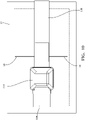
- Figs. 1-10 show various non-limiting examples of a glass mounted electronic assembly 100 that provides a self-contained, direct connection system to electrically conductive antenna elements 12, 14 that are printed on an exterior glass surface 16 or embedded between inner surfaces of laminated glass plates 18 of a glass window 20, 22, such as a rear window of a motor vehicle.
- the glass mounted electronic assembly 100 may contain electronic circuitry for receiving and/or transmitting radio signals, e.g., terrestrial AM/FM radio, satellite radio (e.g., SIRIUS XM satellite radio), digital audio broadcasting (DAB), wireless local area network (WLAN), cellular telephone, vehicle to vehicle (V2V), vehicle to infrastructure (V2I), and/or terrestrial digital video broadcasting (DVB-T/T2) signals.
- radio signals e.g., terrestrial AM/FM radio, satellite radio (e.g., SIRIUS XM satellite radio), digital audio broadcasting (DAB), wireless local area network (WLAN), cellular telephone, vehicle to vehicle (V2V), vehicle to infrastructure (V2I
- the electronic assembly includes a circuit board having a plurality of conductive traces 104, hereinafter referred to as a printed circuit board (PCB) 102.
- the PCB 102 may use a circuit board substrate that is formed of epoxy or polyimide resins. The resin may be reinforced with a woven glass cloth or other matrix such as chopped fibers. Substrates formed of such materials are typically referred to as FR-4 or G-10 type circuit boards.
- the PCB 102 may alternatively be constructed of ceramic or rigid polymer materials. This listing of acceptable substrate materials is not exhaustive and other materials may also be used successfully.
- a layer of conductive material, such as a copper-based material is electroplated on at least one major surface of the PCB 102 .
- the layer of conductive material is then etched to create the conductive traces and second contact regions typically by using a chemical, photochemical, radiation (e.g., laser, electron beam, X-ray, gamma radiation) and/or mechanical etching processes.
- a chemical, photochemical, radiation e.g., laser, electron beam, X-ray, gamma radiation
- the layer of conductive material forming the conductive traces may be screen printed on the substrate.
- the electronic assembly 100 further includes electronic components 106 that are disposed on the PCB 102 and interconnected the plurality of conductive traces 104, thereby forming electronic circuits, such as a radio receiver, a radio transmitter, or a radio transceiver circuit disposed thereon.
- the electronic components 106 may include, but are not limited to, integrated circuits, transistors, diodes, capacitors, inductors, and resistors.
- the electronic assembly illustrated in Figs. 1-10 further includes plurality of coaxial cable connectors 108 that are electrically connected to the plurality of conductive traces 104 on the PCB 102 .
- the coaxial cable connectors 108 illustrated herein conform to the United States Council for Automotive Research (USCAR) USCAR-18 standard.
- the coaxial cable connectors 108 provide electrical connections between the electronic assembly 100 and another electronic circuit in the vehicle (not shown).
- the illustrated embodiment of the electronic assembly 100 has four coaxial connectors, but other embodiments of the electronic assembly 100 may contain more or fewer coaxial connectors, depending on the particular intended application of the electronic assembly.
- the electronic assembly 100 also includes a plurality of flexible electrical terminals 110, 112 that are configured to attach to the antenna elements 12 via electrical contact pads that are disposed on or within the glass surface 16 and electrically connected to the plurality of conductive traces 104 on the PCB 102.
- the electronic assembly 100 additionally includes a housing 114 that encases or encloses the entire PCB 102, a portion of the plurality of flexible electrical terminals 110, 112, and a portion of the coaxial cable connector 108.
- the example housing 114 is formed of a dielectric polymeric material and provides protection for the PCB 102, the plurality of conductive traces 104, and the electronic components 106, particularly from environmental contaminants.
- the housing 114 may be formed by over-molding as described in the method 200 below. so that the housing 114 is in intimate contact with the PCB 102, the portion of the plurality of flexible electrical terminals 110, 112, and the portion of the coaxial cable connector 108.
- the electronic assembly 100 further includes an adhesive layer 116 that is disposed on an outer surface of the housing 114. This adhesive layer 116 is configured to secure the electronic assembly 100 to the glass surface 16.
- the plurality of flexible electrical terminals 110 is formed of a sheet metal material. Each terminal in the plurality of flexible electrical terminals 110 defines meandering or serpentine curves.
- the plurality of flexible electrical terminals 110 is cut from a planar sheet of metal, such as a tin plated copper material, and bent or folded into the desired shape having the serpentine curves. These serpentine curves provide flexibility to the plurality of flexible electrical terminals 112.
- the free ends of the flexible electrical terminals are soldered to the contact pads on the glass surface 16, preferably by a lead-free solder containing indium.
- the plurality of flexible electrical terminals 112 is formed by a flat flexible cable 118.
- the flat flexible cable 118 is disposed between the glass plates 18 and a polymer layer of the glass window 22.
- the conductive antenna elements 14 are embedded between laminated glass plates 18 and electrically interconnected to the electrical contacts, preferably by a lead-free indium containing solder.
- the flat flexible cable 118 is formed of thin conductive layers and is disposed between two polymer layers.
- the two polymer layers are preferably formed of a polyimide polymer, such as KAPTON manufactured by DuPont de Nemours, Inc. of Wilmington, Delaware.
- a method 200 of manufacturing an electronic assembly 100 is shown in the flow chart of Fig. 11 .
- the various steps of the method 200 are outlined below:
- STEP 202 PROVIDE A CIRCUIT BOARD HAVING A PLURALITY OF CONDUCTIVE TRACES AND ELECTRONIC COMPONENTS FORMING A RADIO RECEIVER CIRCUIT DISPOSED THEREON, includes providing a circuit board, e.g. a PCB 102, having a plurality of conductive traces 104 and electronic components 106 forming an electronic circuit disposed thereon;
- a circuit board e.g. a PCB 102, having a plurality of conductive traces 104 and electronic components 106 forming an electronic circuit disposed thereon;
- STEP 204 CONNECT A PLURALITY OF FLEXIBLE ELECTRICAL TERMINALS CONFIGURED TO ATTACH TO ELECTRICAL CONTACTS DISPOSED ON A GLASS SURFACE TO THE PLURALITY OF CONDUCTIVE TRACES, includes connecting a plurality of flexible electrical terminals 110, 112 configured to attach to electrical contacts disposed on a glass surface 16, 18 to the plurality of conductive traces;
- STEP 206 CONNECT A COAXIAL CABLE CONNECTOR TO THE PLURALITY OF CONDUCTIVE TRACES, includes connecting a coaxial cable connector 108 to the plurality of conductive traces 104;
- STEP 208 FORM A HOUSING BY OVER MOLDING THE CIRCUIT BOARD, A PORTION OF THE PLURALITY OF FLEXIBLE ELECTRICAL TERMINALS, AND A PORTION OF THE COAXIAL CABLE CONNECTOR WITH A DIELECTRIC POLYMERIC MATERIAL, includes forming a housing by over molding the PCB 102, a portion of the plurality of flexible electrical terminals 110, 112, and a portion of the coaxial cable connector 108 with a dielectric polymeric material;
- STEP 210 ATTACH THE PLURALITY OF FLEXIBLE ELECTRICAL TERMINALS TO ELECTRICAL CONTACTS DISPOSED ON A GLASS SURFACE HAVING CONDUCTIVE ANTENNA ELEMENTS DISPOSED THEREON THAT ARE ELECTRICALLY INTERCONNECTED TO THE ELECTRICAL CONTACTS, includes attaching the plurality of flexible electrical terminals 110, 112 to electrical contacts disposed on a glass surface 16, 18 having conductive antenna elements 12, 14 disposed thereon that are electrically interconnected to the electrical contacts;
- STEP 212 DISPOSE THE FLAT FLEXIBLE CABLE BETWEEN THE GLASS SURFACE AND A POLYMER LAYER, is an optional step that includes disposing the flat flexible cable 118 between the glass surface 16 and a polymer layer;
- STEP 214 CONNECT THE FLAT FLEXIBLE CABLE TO THE ELECTRICAL CONTACTS WHICH ARE ELECTRICALLY INTERCONNECTED TO CONDUCTIVE ANTENNA ELEMENTS DISPOSED ON THE GLASS SURFACE, is an optional step that includes connecting the flat flexible cable 118 to the electrical contacts which are electrically interconnected to conductive antenna elements 14 disposed on the glass surface 18.
- an electronic assembly that is suitable for mounting to a glass window and a method of manufacturing such an electronic assembly.
- the assembly and method provide the benefit of connecting the electronic assembly directly to antenna elements on the window, thereby eliminating the need for an externally mounted shark fin antenna module as described in the Background section above.
- the assembly and method also eliminate the need for an antenna amplifier module connected by a wire pigtail to the antenna elements on the window.
Landscapes
- Engineering & Computer Science (AREA)
- Microelectronics & Electronic Packaging (AREA)
- Manufacturing & Machinery (AREA)
- Details Of Aerials (AREA)
Abstract
Description
- Antenna modules capable of receiving radio signal at various frequencies from various sources, e.g., terrestrial and satellite radio, have been housed in external antenna assemblies that are mounted on the exterior portions of motor vehicles. These antenna assemblies, typically known as "shark fins" may be mounted to the roof or trunk lid of the vehicle. These antenna assemblies are susceptible to damage due to their location on an exterior surface of the vehicle. These antenna assemblies also require an opening in the exterior of the vehicle to route cabling from electronic systems in the vehicle to the antenna modules. The opening needs to be sealed to prevent water or other contaminants from entering the vehicle interior and failure of that seal can damage the vehicle's headliner or other internal structures and devices due to water intrusion.
- This patent application is directed to an electronic assembly, particularly a radio receiver or transmitter module that is configured to be mounted to a glass surface, such as a motor vehicle window having an antenna pattern printed thereon to which the receiver module is connected. The module has flexible terminals that are configured to attached to the antenna's contact pads. The flexible terminals may be connected to antenna connect pads that are on the outer surface of the glass surface on may be connected to antenna contact pads that are on the inner surface of the glass surface. The electronic assembly may also include a radio transmitter, a radio receiver, or a radio transceiver.
- According to one or more aspects of the present disclosure, an electronic assembly includes a circuit board having a plurality of conductive traces and electronic components forming an electronic circuit, for example a radio receiver circuit, disposed thereon. The electronic assembly also includes a plurality of flexible electrical terminals configured to attach to electrical contacts disposed on a glass surface and electrically connected to the plurality of conductive traces. The electronic assembly further includes a coaxial cable connector electrically connected to the plurality of conductive traces.
- In one or more embodiments of the electronic assembly according to the previous paragraph, the electronic assembly additionally includes a housing encasing the circuit board, a portion of the plurality of flexible electrical terminals, and a portion of the coaxial cable connector.
- In one or more embodiments of the electronic assembly according to any one of the previous paragraphs, the housing encases the circuit board, the portion of the plurality of flexible electrical terminals, and the portion of the coaxial cable connector.
- In one or more embodiments of the electronic assembly according to any one of the previous paragraphs, the housing is in intimate contact with the circuit board, the portion of the plurality of flexible electrical terminals, and the portion of the coaxial cable connector.
- In one or more embodiments of the electronic assembly according to any one of the previous paragraphs, the electronic assembly further includes an adhesive layer disposed on an outer surface of the housing configured to secure the electronic assembly to a planar glass surface.
- In one or more embodiments of the electronic assembly according to any one of the previous paragraphs, the plurality of flexible electrical terminals is formed of a sheet metal material. Each terminal in the plurality of flexible electrical terminals defines serpentine curves. The serpentine curves provide flexibility to the plurality of flexible electrical terminals.
- In one or more embodiments of the electronic assembly according to any one of the previous paragraphs, the electronic assembly also includes the electrical contacts disposed on the glass surface and conductive antenna elements disposed on the glass surface and electrically interconnected to the electrical contacts.
- In one or more embodiments of the electronic assembly according to any one of the previous paragraphs, the plurality of flexible electrical terminals is formed by a flat flexible cable.
- In one or more embodiments of the electronic assembly according to any one of the previous paragraphs, the electronic assembly additionally includes the electrical contacts disposed on the glass surface. The flat flexible cable is disposed between the glass surface and a polymer layer and conductive antenna elements disposed on the glass surface and electrically interconnected to the electrical contacts.
- In one or more embodiments of the electronic assembly according to any one of the previous paragraphs, the plurality of flexible electrical terminals is formed of thin conductive layers and is disposed between two polymer layers.
- In one or more embodiments of the electronic assembly according to any one of the previous paragraphs, the two polymer layers are formed of a polyimide polymer.
- According to one or more aspects of the present disclosure, a method of manufacturing an electronic assembly includes the steps of providing a circuit board having a plurality of conductive traces and electronic components forming a radio receiver circuit disposed thereon, connecting a plurality of flexible electrical terminals configured to attach to electrical contacts disposed on a glass surface to the plurality of conductive traces, connecting a coaxial cable connector to the plurality of conductive traces, and forming a housing by over molding the circuit board, a portion of the plurality of flexible electrical terminals, and a portion of the coaxial cable connector with a dielectric polymeric material.
- In one or more embodiments of the method according to the previous paragraph, the housing is in intimate contact with the circuit board, the portion of the plurality of flexible electrical terminals, and the portion of the coaxial cable connector.
- In one or more embodiments of the method according to any one of the previous paragraphs, the housing is in intimate contact with the circuit board, the portion of the plurality of flexible electrical terminals, and the portion of the coaxial cable connector.
- In one or more embodiments of the method according to any one of the previous paragraphs, the method further includes the steps of attaching the plurality of flexible electrical terminals to electrical contacts disposed on a glass surface having conductive antenna elements disposed thereon that are electrically interconnected to the electrical contacts and attaching the housing to the glass surface.
- In one or more embodiments of the method according to any one of the previous paragraphs, the plurality of flexible electrical terminals is formed by a flat flexible cable. The method also includes the steps of disposing the flat flexible cable between the glass surface and a polymer layer and connecting the flat flexible cable to the electrical contacts which are electrically interconnected to conductive antenna elements disposed on the glass surface.
- In one or more embodiments of the method according to any one of the previous paragraphs, the plurality of flexible electrical terminals is formed of a sheet metal material. Each terminal in the plurality of flexible electrical terminals defines serpentine curves. The serpentine curves provide flexibility to the plurality of flexible electrical terminals.
-
Fig. 1 is a perspective view of a glass mounted radio receiver assembly according to some embodiments; -
Fig. 2 is a perspective cut-away view of the glass mounted radio receiver assembly ofFig. 1 according to some embodiments; -
Fig. 3 is a side plan view of the glass mounted radio receiver assembly ofFig. 1 according to some embodiments; -
Fig. 4 is an end plan view of the glass mounted radio receiver assembly ofFig. 1 according to some embodiments; -
Fig. 5 is a top plan view of the glass mounted radio receiver assembly ofFig. 1 according to some embodiments; -
Fig. 6 is a perspective view of a glass mounted radio receiver assembly according to some embodiments; -
Fig. 7 is a perspective cut-away view of the glass mounted radio receiver assembly ofFig. 6 according to some embodiments; -
Fig. 8 is a side plan view of the glass mounted radio receiver assembly ofFig. 6 according to some embodiments; -
Fig. 9 is an end plan view of the glass mounted radio receiver assembly ofFig. 6 according to some embodiments; -
Fig. 10 is a top plan view of the glass mounted radio receiver assembly ofFig. 6 according to some embodiments; and -
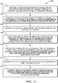
Fig. 11 is a flow chart of a method of manufacturing an electronic assembly according to some embodiments. -
Figs. 1-10 show various non-limiting examples of a glass mountedelectronic assembly 100 that provides a self-contained, direct connection system to electricallyconductive antenna elements exterior glass surface 16 or embedded between inner surfaces of laminatedglass plates 18 of aglass window electronic assembly 100 may contain electronic circuitry for receiving and/or transmitting radio signals, e.g., terrestrial AM/FM radio, satellite radio (e.g., SIRIUS XM satellite radio), digital audio broadcasting (DAB), wireless local area network (WLAN), cellular telephone, vehicle to vehicle (V2V), vehicle to infrastructure (V2I), and/or terrestrial digital video broadcasting (DVB-T/T2) signals. - The electronic assembly includes a circuit board having a plurality of
conductive traces 104, hereinafter referred to as a printed circuit board (PCB) 102. The PCB 102 may use a circuit board substrate that is formed of epoxy or polyimide resins. The resin may be reinforced with a woven glass cloth or other matrix such as chopped fibers. Substrates formed of such materials are typically referred to as FR-4 or G-10 type circuit boards. The PCB 102 may alternatively be constructed of ceramic or rigid polymer materials. This listing of acceptable substrate materials is not exhaustive and other materials may also be used successfully. A layer of conductive material, such as a copper-based material is electroplated on at least one major surface of thePCB 102 . The layer of conductive material is then etched to create the conductive traces and second contact regions typically by using a chemical, photochemical, radiation (e.g., laser, electron beam, X-ray, gamma radiation) and/or mechanical etching processes. Alternatively, the layer of conductive material forming the conductive traces may be screen printed on the substrate. - The
electronic assembly 100 further includeselectronic components 106 that are disposed on thePCB 102 and interconnected the plurality ofconductive traces 104, thereby forming electronic circuits, such as a radio receiver, a radio transmitter, or a radio transceiver circuit disposed thereon. Theelectronic components 106 may include, but are not limited to, integrated circuits, transistors, diodes, capacitors, inductors, and resistors. - The electronic assembly illustrated in
Figs. 1-10 further includes plurality ofcoaxial cable connectors 108 that are electrically connected to the plurality ofconductive traces 104 on thePCB 102 . Thecoaxial cable connectors 108 illustrated herein conform to the United States Council for Automotive Research (USCAR) USCAR-18 standard. Thecoaxial cable connectors 108 provide electrical connections between theelectronic assembly 100 and another electronic circuit in the vehicle (not shown). The illustrated embodiment of theelectronic assembly 100 has four coaxial connectors, but other embodiments of theelectronic assembly 100 may contain more or fewer coaxial connectors, depending on the particular intended application of the electronic assembly. - The
electronic assembly 100 also includes a plurality of flexibleelectrical terminals antenna elements 12 via electrical contact pads that are disposed on or within theglass surface 16 and electrically connected to the plurality ofconductive traces 104 on thePCB 102. - The
electronic assembly 100 additionally includes ahousing 114 that encases or encloses theentire PCB 102, a portion of the plurality of flexibleelectrical terminals coaxial cable connector 108. Theexample housing 114 is formed of a dielectric polymeric material and provides protection for thePCB 102, the plurality ofconductive traces 104, and theelectronic components 106, particularly from environmental contaminants. Thehousing 114 may be formed by over-molding as described in themethod 200 below. so that thehousing 114 is in intimate contact with thePCB 102, the portion of the plurality of flexibleelectrical terminals coaxial cable connector 108. - The
electronic assembly 100 further includes anadhesive layer 116 that is disposed on an outer surface of thehousing 114. Thisadhesive layer 116 is configured to secure theelectronic assembly 100 to theglass surface 16. - As shown in
Figs. 1-5 , the plurality of flexibleelectrical terminals 110 is formed of a sheet metal material. Each terminal in the plurality of flexibleelectrical terminals 110 defines meandering or serpentine curves. The plurality of flexibleelectrical terminals 110 is cut from a planar sheet of metal, such as a tin plated copper material, and bent or folded into the desired shape having the serpentine curves. These serpentine curves provide flexibility to the plurality of flexibleelectrical terminals 112. The free ends of the flexible electrical terminals are soldered to the contact pads on theglass surface 16, preferably by a lead-free solder containing indium. - As shown in
Figs. 6-10 , the plurality of flexibleelectrical terminals 112 is formed by a flatflexible cable 118. The flatflexible cable 118 is disposed between theglass plates 18 and a polymer layer of theglass window 22. Theconductive antenna elements 14 are embedded betweenlaminated glass plates 18 and electrically interconnected to the electrical contacts, preferably by a lead-free indium containing solder. - The flat
flexible cable 118 is formed of thin conductive layers and is disposed between two polymer layers. The two polymer layers are preferably formed of a polyimide polymer, such as KAPTON manufactured by DuPont de Nemours, Inc. of Wilmington, Delaware. - A
method 200 of manufacturing anelectronic assembly 100 is shown in the flow chart ofFig. 11 . The various steps of themethod 200 are outlined below: -
STEP 202, PROVIDE A CIRCUIT BOARD HAVING A PLURALITY OF CONDUCTIVE TRACES AND ELECTRONIC COMPONENTS FORMING A RADIO RECEIVER CIRCUIT DISPOSED THEREON, includes providing a circuit board, e.g. aPCB 102, having a plurality ofconductive traces 104 andelectronic components 106 forming an electronic circuit disposed thereon; -
STEP 204, CONNECT A PLURALITY OF FLEXIBLE ELECTRICAL TERMINALS CONFIGURED TO ATTACH TO ELECTRICAL CONTACTS DISPOSED ON A GLASS SURFACE TO THE PLURALITY OF CONDUCTIVE TRACES, includes connecting a plurality of flexibleelectrical terminals glass surface -
STEP 206, CONNECT A COAXIAL CABLE CONNECTOR TO THE PLURALITY OF CONDUCTIVE TRACES, includes connecting acoaxial cable connector 108 to the plurality ofconductive traces 104; -
STEP 208, FORM A HOUSING BY OVER MOLDING THE CIRCUIT BOARD, A PORTION OF THE PLURALITY OF FLEXIBLE ELECTRICAL TERMINALS, AND A PORTION OF THE COAXIAL CABLE CONNECTOR WITH A DIELECTRIC POLYMERIC MATERIAL, includes forming a housing by over molding thePCB 102, a portion of the plurality of flexibleelectrical terminals coaxial cable connector 108 with a dielectric polymeric material; -
STEP 210, ATTACH THE PLURALITY OF FLEXIBLE ELECTRICAL TERMINALS TO ELECTRICAL CONTACTS DISPOSED ON A GLASS SURFACE HAVING CONDUCTIVE ANTENNA ELEMENTS DISPOSED THEREON THAT ARE ELECTRICALLY INTERCONNECTED TO THE ELECTRICAL CONTACTS, includes attaching the plurality of flexibleelectrical terminals glass surface conductive antenna elements -
STEP 212, DISPOSE THE FLAT FLEXIBLE CABLE BETWEEN THE GLASS SURFACE AND A POLYMER LAYER, is an optional step that includes disposing the flatflexible cable 118 between theglass surface 16 and a polymer layer; and -
STEP 214, CONNECT THE FLAT FLEXIBLE CABLE TO THE ELECTRICAL CONTACTS WHICH ARE ELECTRICALLY INTERCONNECTED TO CONDUCTIVE ANTENNA ELEMENTS DISPOSED ON THE GLASS SURFACE, is an optional step that includes connecting the flatflexible cable 118 to the electrical contacts which are electrically interconnected toconductive antenna elements 14 disposed on theglass surface 18. - Accordingly, an electronic assembly that is suitable for mounting to a glass window and a method of manufacturing such an electronic assembly is provided. The assembly and method provide the benefit of connecting the electronic assembly directly to antenna elements on the window, thereby eliminating the need for an externally mounted shark fin antenna module as described in the Background section above. The assembly and method also eliminate the need for an antenna amplifier module connected by a wire pigtail to the antenna elements on the window.
- While the invention has been described with reference to an exemplary embodiment(s), it will be understood by those skilled in the art that various changes may be made, and equivalents may be substituted for elements thereof without departing from the scope of the invention. In addition, many modifications may be made to adapt a particular situation or material to the teachings of the invention without departing from the essential scope thereof. Therefore, it is intended that the invention is not limited to the disclosed embodiment(s), but that the invention will include all embodiments falling within the scope of the appended claims.
Claims (15)
- An electronic assembly (100), comprising:a circuit board (102) having a plurality of conductive traces (104) and electronic components (106) forming an electronic circuit disposed thereon;a plurality of flexible electrical terminals (110) configured to attach to electrical contacts disposed on a glass surface (16) and electrically connected to the plurality of conductive traces (104) ; anda coaxial cable connector (108) electrically connected to the plurality of conductive traces (104).
- The electronic assembly (100) according to claim 1, further comprising:a housing (114) enclosing the circuit board (102), a portion of the plurality of flexible electrical terminals (110), and a portion of the coaxial cable connector (108).
- The electronic assembly (100) according to claim 2, wherein the housing (114) encases the circuit board (102), the portion of the plurality of flexible electrical terminals (110), and the portion of the coaxial cable connector (108).
- The electronic assembly (100) according to claim 2 or 3, wherein the housing (114) is in intimate contact with the circuit board (102), the portion of the plurality of flexible electrical terminals (110), and the portion of the coaxial cable connector (108).
- The electronic assembly (100) according to any one of claims 2 to 4, further comprising:an adhesive layer (116) disposed on an outer surface of the housing (114) configured to secure the electronic assembly (100) to the planar glass surface (16).
- The electronic assembly (100) according to claim 6, further comprising:the electrical contacts disposed on the glass surface (16); andconductive antenna elements disposed on the glass surface (16) and electrically interconnected to the electrical contacts.
- The electronic assembly (100) according to any one of claims 2 to 6, wherein the plurality of flexible electrical terminals (110) is formed by a flat flexible cable.
- The electronic assembly (100) according to claim 7, further comprising:the electrical contacts disposed on the glass surface (18), wherein the flat flexible cable (118) is disposed between the glass surface (18) and a polymer layer; andconductive antenna elements disposed on the glass surface (18) and electrically interconnected to the electrical contacts.
- The electronic assembly (100) according to claim 7 or 8, wherein the plurality of flexible electrical terminals (110) is formed of thin conductive layers and is disposed between two polymer layers.
- The electronic assembly (100) according to claim 9, wherein the two polymer layers are formed of a polyimide polymer.
- The electronic assembly (100) according to any one of the preceding claims, wherein the plurality of flexible electrical terminals (110) is formed of a sheet metal material, wherein each terminal in the plurality of flexible electrical terminals (110) defines serpentine curves, and wherein the serpentine curves provide flexibility to the plurality of flexible electrical terminals (110).
- A method (200) of manufacturing an electronic assembly (100), comprising:providing a circuit board (102) having a plurality of conductive traces (104) and electronic components (106) forming an electronic circuit disposed thereon;connecting a plurality of flexible electrical terminals (110) configured to attach to electrical contacts disposed on a glass surface (16) to the plurality of conductive traces (104);connecting a coaxial cable connector (108) to the plurality of conductive traces (104); andforming a housing (114) by over molding the circuit board (102), a portion of the plurality of flexible electrical terminals (110), and a portion of the coaxial cable connector (108) with a dielectric polymeric material.
- The method (200) according to claim 12, further comprising:attaching the plurality of flexible electrical terminals (110) to electrical contacts disposed on a glass surface (16) having conductive antenna elements disposed thereon that are electrically interconnected to the electrical contacts; andattaching the housing (114) to the glass surface (16).
- The method (200) according to claim 12 or 13, wherein the plurality of flexible electrical terminals (110) is formed by a flat flexible cable (118) wherein the method further comprises:disposing the flat flexible cable (118) between the glass surface (18) and a polymer layer; andconnecting the flat flexible cable (118) to the electrical contacts which are electrically interconnected to conductive antenna elements disposed on the glass surface (18).
- The method (200) according to any one of claims 12 to 14, wherein the plurality of flexible electrical terminals (110) is formed of a sheet metal material, wherein each terminal in the plurality of flexible electrical terminals (110) defines serpentine curves, and wherein the serpentine curves provide flexibility to the plurality of flexible electrical terminals (110).
Applications Claiming Priority (2)
| Application Number | Priority Date | Filing Date | Title |
|---|---|---|---|
| US202163137467P | 2021-01-14 | 2021-01-14 | |
| US17/569,079 US12126126B2 (en) | 2021-01-14 | 2022-01-05 | Glass mounted electronic assembly |
Publications (2)
| Publication Number | Publication Date |
|---|---|
| EP4030562A1 true EP4030562A1 (en) | 2022-07-20 |
| EP4030562B1 EP4030562B1 (en) | 2026-03-04 |
Family
ID=79601470
Family Applications (1)
| Application Number | Title | Priority Date | Filing Date |
|---|---|---|---|
| EP22151347.6A Active EP4030562B1 (en) | 2021-01-14 | 2022-01-13 | Glass mounted electronic assembly |
Country Status (3)
| Country | Link |
|---|---|
| US (1) | US12126126B2 (en) |
| EP (1) | EP4030562B1 (en) |
| CN (1) | CN115459017A (en) |
Families Citing this family (2)
| Publication number | Priority date | Publication date | Assignee | Title |
|---|---|---|---|---|
| US12500334B2 (en) * | 2022-11-11 | 2025-12-16 | Lg Electronics Inc. | Transparent antenna module and method for manufacturing the same |
| WO2024143636A1 (en) * | 2022-12-30 | 2024-07-04 | 엘지전자 주식회사 | Antenna assembly |
Citations (3)
| Publication number | Priority date | Publication date | Assignee | Title |
|---|---|---|---|---|
| DE102010049103A1 (en) * | 2010-10-21 | 2012-04-26 | Daimler Ag | Contact device for contacting conductive structure of windscreen of motor car, has contact elements comprising set of free end regions arranged for contacting structure, integrally formed and connected with cable by plug-in connection |
| DE202018105085U1 (en) * | 2017-09-20 | 2018-09-26 | U. D. Electronic Corp. | Electrical connector with filter function |
| US10205216B2 (en) * | 2016-05-06 | 2019-02-12 | GM Global Technology Operations LLC | Thin film antenna to FAKRA connector |
Family Cites Families (12)
| Publication number | Priority date | Publication date | Assignee | Title |
|---|---|---|---|---|
| JPS6141204A (en) * | 1984-08-01 | 1986-02-27 | Nissan Motor Co Ltd | Terminal processing structue of laminated glass enclosed antenna wire |
| JPH04116411U (en) * | 1991-03-28 | 1992-10-19 | セントラル硝子株式会社 | Glass antenna connection structure |
| DE4332320C1 (en) * | 1993-09-23 | 1995-05-04 | Ver Glaswerke Gmbh | Method for producing a laminated glass pane with inserted antenna wires |
| US6591084B1 (en) * | 1998-04-27 | 2003-07-08 | General Dynamics Decision Systems, Inc. | Satellite based data transfer and delivery system |
| DE19856663C2 (en) * | 1998-12-09 | 2003-04-03 | Saint Gobain Sekurit D Gmbh | Contact device for an electrical functional element arranged on a window pane |
| KR200361870Y1 (en) * | 2004-06-21 | 2004-09-13 | 김수현 | A film antenna for vehicle |
| US8814601B1 (en) * | 2011-06-06 | 2014-08-26 | Nuvotronics, Llc | Batch fabricated microconnectors |
| US9564674B2 (en) * | 2014-02-03 | 2017-02-07 | Pittsburgh Glass Works, Llc | Window antenna connector with impedance matching |
| EP3089272A1 (en) * | 2015-04-29 | 2016-11-02 | AGC Glass Europe | Glazing panel having an electrically conductive connector |
| EP3447846A1 (en) * | 2017-08-25 | 2019-02-27 | AGC Glass Europe | Glazing panel having an electrically conductive connector |
| US11721880B2 (en) * | 2018-03-30 | 2023-08-08 | Agc Glass Europe | Laminated glazing panel having an antenna |
| JP7178222B2 (en) * | 2018-09-19 | 2022-11-25 | 日本板硝子株式会社 | vehicle glass module |
-
2022
- 2022-01-05 US US17/569,079 patent/US12126126B2/en active Active
- 2022-01-13 CN CN202210038893.3A patent/CN115459017A/en active Pending
- 2022-01-13 EP EP22151347.6A patent/EP4030562B1/en active Active
Patent Citations (3)
| Publication number | Priority date | Publication date | Assignee | Title |
|---|---|---|---|---|
| DE102010049103A1 (en) * | 2010-10-21 | 2012-04-26 | Daimler Ag | Contact device for contacting conductive structure of windscreen of motor car, has contact elements comprising set of free end regions arranged for contacting structure, integrally formed and connected with cable by plug-in connection |
| US10205216B2 (en) * | 2016-05-06 | 2019-02-12 | GM Global Technology Operations LLC | Thin film antenna to FAKRA connector |
| DE202018105085U1 (en) * | 2017-09-20 | 2018-09-26 | U. D. Electronic Corp. | Electrical connector with filter function |
Also Published As
| Publication number | Publication date |
|---|---|
| EP4030562B1 (en) | 2026-03-04 |
| US12126126B2 (en) | 2024-10-22 |
| CN115459017A (en) | 2022-12-09 |
| US20220294164A1 (en) | 2022-09-15 |
Similar Documents
| Publication | Publication Date | Title |
|---|---|---|
| US6331838B1 (en) | Flexible vehicle antenna | |
| CN107453028B (en) | Connector for film antenna to FAKRA | |
| US6879849B2 (en) | In-built antenna for mobile communication device | |
| US12126126B2 (en) | Glass mounted electronic assembly | |
| US10879598B2 (en) | Antenna unit | |
| JP4312597B2 (en) | Antenna window with high frequency components | |
| KR20150123169A (en) | Cable connector assembly for a communication system | |
| WO2007082727A1 (en) | Rf connector mounting means | |
| JP2020532068A (en) | Glass panel with conductive connector | |
| JP2013201511A (en) | Vehicle antenna integrated wireless communication module, vehicle wireless communication device, and manufacturing method for vehicle wireless communication device | |
| US9893420B2 (en) | Wireless module with plural in-plane terminals | |
| US20100033940A1 (en) | Inter-board coupling connector and circuit board device using inter-board coupling connector | |
| US11621477B2 (en) | Antenna device and antenna apparatus | |
| US20040266345A1 (en) | Antenna unit | |
| JP2004320431A (en) | Planar antenna device | |
| CN114624654A (en) | Radar structure and vehicle-mounted radar equipment | |
| US7086868B2 (en) | Board-to-board connector | |
| US20250253549A1 (en) | Antenna For Telematics Control Unit | |
| JP2017069608A (en) | Communication device | |
| JP2006332784A (en) | Planar antenna system | |
| CN1225817C (en) | planar antenna device | |
| US12463344B2 (en) | Slot antenna | |
| CN223260873U (en) | Grounding device and equipment | |
| CN223141030U (en) | Antenna feed device and antenna device | |
| US20230115962A1 (en) | Radio frequency connector, antenna assembly, and base station antenna |
Legal Events
| Date | Code | Title | Description |
|---|---|---|---|
| PUAI | Public reference made under article 153(3) epc to a published international application that has entered the european phase |
Free format text: ORIGINAL CODE: 0009012 |
|
| STAA | Information on the status of an ep patent application or granted ep patent |
Free format text: STATUS: THE APPLICATION HAS BEEN PUBLISHED |
|
| AK | Designated contracting states |
Kind code of ref document: A1 Designated state(s): AL AT BE BG CH CY CZ DE DK EE ES FI FR GB GR HR HU IE IS IT LI LT LU LV MC MK MT NL NO PL PT RO RS SE SI SK SM TR |
|
| STAA | Information on the status of an ep patent application or granted ep patent |
Free format text: STATUS: REQUEST FOR EXAMINATION WAS MADE |
|
| 17P | Request for examination filed |
Effective date: 20221220 |
|
| RBV | Designated contracting states (corrected) |
Designated state(s): AL AT BE BG CH CY CZ DE DK EE ES FI FR GB GR HR HU IE IS IT LI LT LU LV MC MK MT NL NO PL PT RO RS SE SI SK SM TR |
|
| RAP3 | Party data changed (applicant data changed or rights of an application transferred) |
Owner name: APTIV TECHNOLOGIES LIMITED |
|
| STAA | Information on the status of an ep patent application or granted ep patent |
Free format text: STATUS: EXAMINATION IS IN PROGRESS |
|
| 17Q | First examination report despatched |
Effective date: 20240307 |
|
| RAP1 | Party data changed (applicant data changed or rights of an application transferred) |
Owner name: APTIV TECHNOLOGIES AG |
|
| RAP3 | Party data changed (applicant data changed or rights of an application transferred) |
Owner name: APTIV TECHNOLOGIES AG |
|
| GRAP | Despatch of communication of intention to grant a patent |
Free format text: ORIGINAL CODE: EPIDOSNIGR1 |
|
| STAA | Information on the status of an ep patent application or granted ep patent |
Free format text: STATUS: GRANT OF PATENT IS INTENDED |
|
| RIC1 | Information provided on ipc code assigned before grant |
Ipc: H01R 12/57 20110101AFI20251203BHEP Ipc: B32B 17/00 20060101ALI20251203BHEP Ipc: H01Q 1/00 20060101ALI20251203BHEP Ipc: H01R 12/91 20110101ALI20251203BHEP Ipc: H01R 24/50 20110101ALI20251203BHEP Ipc: H05K 1/00 20060101ALI20251203BHEP Ipc: H05K 5/00 20060101ALI20251203BHEP Ipc: H01R 13/66 20060101ALI20251203BHEP Ipc: H01R 103/00 20060101ALN20251203BHEP |
|
| INTG | Intention to grant announced |
Effective date: 20251211 |
|
| GRAS | Grant fee paid |
Free format text: ORIGINAL CODE: EPIDOSNIGR3 |
|
| GRAA | (expected) grant |
Free format text: ORIGINAL CODE: 0009210 |
|
| STAA | Information on the status of an ep patent application or granted ep patent |
Free format text: STATUS: THE PATENT HAS BEEN GRANTED |
|
| P01 | Opt-out of the competence of the unified patent court (upc) registered |
Free format text: CASE NUMBER: UPC_APP_0001034_4030562/2026 Effective date: 20260113 |
|
| AK | Designated contracting states |
Kind code of ref document: B1 Designated state(s): AL AT BE BG CH CY CZ DE DK EE ES FI FR GB GR HR HU IE IS IT LI LT LU LV MC MK MT NL NO PL PT RO RS SE SI SK SM TR |
|
| REG | Reference to a national code |
Ref country code: CH Ref legal event code: F10 Free format text: ST27 STATUS EVENT CODE: U-0-0-F10-F00 (AS PROVIDED BY THE NATIONAL OFFICE) Effective date: 20260304 Ref country code: GB Ref legal event code: FG4D |
|
| REG | Reference to a national code |
Ref country code: IE Ref legal event code: FG4D |
|
| REG | Reference to a national code |
Ref country code: DE Ref legal event code: R096 Ref document number: 602022031424 Country of ref document: DE |
|
| PG25 | Lapsed in a contracting state [announced via postgrant information from national office to epo] |
Ref country code: RS Free format text: LAPSE BECAUSE OF FAILURE TO SUBMIT A TRANSLATION OF THE DESCRIPTION OR TO PAY THE FEE WITHIN THE PRESCRIBED TIME-LIMIT Effective date: 20260604 |
|
| PG25 | Lapsed in a contracting state [announced via postgrant information from national office to epo] |
Ref country code: ES Free format text: LAPSE BECAUSE OF FAILURE TO SUBMIT A TRANSLATION OF THE DESCRIPTION OR TO PAY THE FEE WITHIN THE PRESCRIBED TIME-LIMIT Effective date: 20260304 |
|
| REG | Reference to a national code |
Ref country code: NL Ref legal event code: MP Effective date: 20260304 |
|
| PG25 | Lapsed in a contracting state [announced via postgrant information from national office to epo] |
Ref country code: PL Free format text: LAPSE BECAUSE OF FAILURE TO SUBMIT A TRANSLATION OF THE DESCRIPTION OR TO PAY THE FEE WITHIN THE PRESCRIBED TIME-LIMIT Effective date: 20260304 |
|
| PG25 | Lapsed in a contracting state [announced via postgrant information from national office to epo] |
Ref country code: GR Free format text: LAPSE BECAUSE OF FAILURE TO SUBMIT A TRANSLATION OF THE DESCRIPTION OR TO PAY THE FEE WITHIN THE PRESCRIBED TIME-LIMIT Effective date: 20260605 |
|
| REG | Reference to a national code |
Ref country code: LT Ref legal event code: MG9D |
|
| PG25 | Lapsed in a contracting state [announced via postgrant information from national office to epo] |
Ref country code: LT Free format text: LAPSE BECAUSE OF FAILURE TO SUBMIT A TRANSLATION OF THE DESCRIPTION OR TO PAY THE FEE WITHIN THE PRESCRIBED TIME-LIMIT Effective date: 20260304 |
|
| PG25 | Lapsed in a contracting state [announced via postgrant information from national office to epo] |
Ref country code: NO Free format text: LAPSE BECAUSE OF FAILURE TO SUBMIT A TRANSLATION OF THE DESCRIPTION OR TO PAY THE FEE WITHIN THE PRESCRIBED TIME-LIMIT Effective date: 20260604 |
|
| PG25 | Lapsed in a contracting state [announced via postgrant information from national office to epo] |
Ref country code: FI Free format text: LAPSE BECAUSE OF FAILURE TO SUBMIT A TRANSLATION OF THE DESCRIPTION OR TO PAY THE FEE WITHIN THE PRESCRIBED TIME-LIMIT Effective date: 20260304 Ref country code: SE Free format text: LAPSE BECAUSE OF FAILURE TO SUBMIT A TRANSLATION OF THE DESCRIPTION OR TO PAY THE FEE WITHIN THE PRESCRIBED TIME-LIMIT Effective date: 20260304 |
|
| PG25 | Lapsed in a contracting state [announced via postgrant information from national office to epo] |
Ref country code: HR Free format text: LAPSE BECAUSE OF FAILURE TO SUBMIT A TRANSLATION OF THE DESCRIPTION OR TO PAY THE FEE WITHIN THE PRESCRIBED TIME-LIMIT Effective date: 20260304 |
|
| PG25 | Lapsed in a contracting state [announced via postgrant information from national office to epo] |
Ref country code: LV Free format text: LAPSE BECAUSE OF FAILURE TO SUBMIT A TRANSLATION OF THE DESCRIPTION OR TO PAY THE FEE WITHIN THE PRESCRIBED TIME-LIMIT Effective date: 20260304 |
|
| PG25 | Lapsed in a contracting state [announced via postgrant information from national office to epo] |
Ref country code: BG Free format text: LAPSE BECAUSE OF FAILURE TO SUBMIT A TRANSLATION OF THE DESCRIPTION OR TO PAY THE FEE WITHIN THE PRESCRIBED TIME-LIMIT Effective date: 20260304 |