EP4030543A1 - Apparatus and method for manufacturing secondary battery - Google Patents
Apparatus and method for manufacturing secondary battery Download PDFInfo
- Publication number
- EP4030543A1 EP4030543A1 EP21218278.6A EP21218278A EP4030543A1 EP 4030543 A1 EP4030543 A1 EP 4030543A1 EP 21218278 A EP21218278 A EP 21218278A EP 4030543 A1 EP4030543 A1 EP 4030543A1
- Authority
- EP
- European Patent Office
- Prior art keywords
- housing
- mono frame
- end plate
- pair
- support
- Prior art date
- Legal status (The legal status is an assumption and is not a legal conclusion. Google has not performed a legal analysis and makes no representation as to the accuracy of the status listed.)
- Pending
Links
- 238000004519 manufacturing process Methods 0.000 title claims abstract description 18
- 238000000034 method Methods 0.000 title claims description 36
- 238000003466 welding Methods 0.000 claims description 52
- 238000003825 pressing Methods 0.000 claims description 31
- 239000003638 chemical reducing agent Substances 0.000 claims description 11
- RYGMFSIKBFXOCR-UHFFFAOYSA-N Copper Chemical compound [Cu] RYGMFSIKBFXOCR-UHFFFAOYSA-N 0.000 description 2
- XAGFODPZIPBFFR-UHFFFAOYSA-N aluminium Chemical compound [Al] XAGFODPZIPBFFR-UHFFFAOYSA-N 0.000 description 2
- 229910052782 aluminium Inorganic materials 0.000 description 2
- 229910052802 copper Inorganic materials 0.000 description 2
- 239000010949 copper Substances 0.000 description 2
- 238000007789 sealing Methods 0.000 description 2
- 239000000853 adhesive Substances 0.000 description 1
- 230000001070 adhesive effect Effects 0.000 description 1
- 230000008878 coupling Effects 0.000 description 1
- 238000010168 coupling process Methods 0.000 description 1
- 238000005859 coupling reaction Methods 0.000 description 1
- 230000007547 defect Effects 0.000 description 1
- 238000003780 insertion Methods 0.000 description 1
- 230000037431 insertion Effects 0.000 description 1
- 239000000463 material Substances 0.000 description 1
- 239000000126 substance Substances 0.000 description 1
Images



Classifications
-
- H—ELECTRICITY
- H01—ELECTRIC ELEMENTS
- H01M—PROCESSES OR MEANS, e.g. BATTERIES, FOR THE DIRECT CONVERSION OF CHEMICAL ENERGY INTO ELECTRICAL ENERGY
- H01M50/00—Constructional details or processes of manufacture of the non-active parts of electrochemical cells other than fuel cells, e.g. hybrid cells
- H01M50/20—Mountings; Secondary casings or frames; Racks, modules or packs; Suspension devices; Shock absorbers; Transport or carrying devices; Holders
- H01M50/204—Racks, modules or packs for multiple batteries or multiple cells
- H01M50/207—Racks, modules or packs for multiple batteries or multiple cells characterised by their shape
- H01M50/209—Racks, modules or packs for multiple batteries or multiple cells characterised by their shape adapted for prismatic or rectangular cells
-
- H—ELECTRICITY
- H01—ELECTRIC ELEMENTS
- H01M—PROCESSES OR MEANS, e.g. BATTERIES, FOR THE DIRECT CONVERSION OF CHEMICAL ENERGY INTO ELECTRICAL ENERGY
- H01M50/00—Constructional details or processes of manufacture of the non-active parts of electrochemical cells other than fuel cells, e.g. hybrid cells
- H01M50/20—Mountings; Secondary casings or frames; Racks, modules or packs; Suspension devices; Shock absorbers; Transport or carrying devices; Holders
- H01M50/204—Racks, modules or packs for multiple batteries or multiple cells
-
- B—PERFORMING OPERATIONS; TRANSPORTING
- B23—MACHINE TOOLS; METAL-WORKING NOT OTHERWISE PROVIDED FOR
- B23K—SOLDERING OR UNSOLDERING; WELDING; CLADDING OR PLATING BY SOLDERING OR WELDING; CUTTING BY APPLYING HEAT LOCALLY, e.g. FLAME CUTTING; WORKING BY LASER BEAM
- B23K26/00—Working by laser beam, e.g. welding, cutting or boring
- B23K26/20—Bonding
- B23K26/21—Bonding by welding
- B23K26/24—Seam welding
-
- H—ELECTRICITY
- H01—ELECTRIC ELEMENTS
- H01M—PROCESSES OR MEANS, e.g. BATTERIES, FOR THE DIRECT CONVERSION OF CHEMICAL ENERGY INTO ELECTRICAL ENERGY
- H01M10/00—Secondary cells; Manufacture thereof
- H01M10/04—Construction or manufacture in general
- H01M10/0404—Machines for assembling batteries
-
- H—ELECTRICITY
- H01—ELECTRIC ELEMENTS
- H01M—PROCESSES OR MEANS, e.g. BATTERIES, FOR THE DIRECT CONVERSION OF CHEMICAL ENERGY INTO ELECTRICAL ENERGY
- H01M10/00—Secondary cells; Manufacture thereof
- H01M10/04—Construction or manufacture in general
- H01M10/0481—Compression means other than compression means for stacks of electrodes and separators
-
- H—ELECTRICITY
- H01—ELECTRIC ELEMENTS
- H01M—PROCESSES OR MEANS, e.g. BATTERIES, FOR THE DIRECT CONVERSION OF CHEMICAL ENERGY INTO ELECTRICAL ENERGY
- H01M50/00—Constructional details or processes of manufacture of the non-active parts of electrochemical cells other than fuel cells, e.g. hybrid cells
- H01M50/20—Mountings; Secondary casings or frames; Racks, modules or packs; Suspension devices; Shock absorbers; Transport or carrying devices; Holders
-
- B—PERFORMING OPERATIONS; TRANSPORTING
- B23—MACHINE TOOLS; METAL-WORKING NOT OTHERWISE PROVIDED FOR
- B23K—SOLDERING OR UNSOLDERING; WELDING; CLADDING OR PLATING BY SOLDERING OR WELDING; CUTTING BY APPLYING HEAT LOCALLY, e.g. FLAME CUTTING; WORKING BY LASER BEAM
- B23K2101/00—Articles made by soldering, welding or cutting
- B23K2101/36—Electric or electronic devices
Definitions
- the present disclosure relates to an apparatus and method for manufacturing a secondary battery.
- a main process for manufacturing a secondary battery may include a cell stacking process of stacking a plurality of cells to manufacture one module, a bus bar assembly process of electrically connecting copper to aluminum, a lead welding process of performing welding by using a laser to fix copper and aluminum to a bus bar, a module insertion process of inserting the module into a hexahedral mono frame to protect the module, and an end plate welding of sealing the mono frame using the laser so that foreign substances are not introduced into the module.
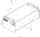
- Fig. 1 is a perspective view illustrating an outer appearance of a secondary battery unit into which a cell module is inserted into a mono frame.
- a cell module 21 on which in a lead welding process is performed has both opened side surfaces and is inserted into a hexahedral mono frame 22 having an opened inside.
- the cell module 21 may be understood to mean a secondary battery in which a positive electrode lead and a negative electrode lead are attached to both ends of each of a plurality of stacked cells.
- both opened side surfaces of the mono frame 22 are shielded by a rectangular plate that is called an end plate 23.
- a secondary battery product in which the welding process is completed, may be defined as a secondary battery unit 20.
- the secondary battery product When a material called a battery management system (BMS) is attached to the secondary battery unit 20, the secondary battery product may be defined as a battery pack or a secondary battery pack. That is, the secondary battery unit 20 may be understood as a product before the BMS is attached.
- BMS battery management system
- a welding device used to weld the end plate 23 to both side surfaces of the mono frame 22 performs welding while the end plate 23 is fitted into both ends of the mono frame 22. Furthermore, a jig or clamp member constituting the welding device welds four edges of the end plate while rotating in a state of holding only the end plate 23.
- the mono frame 22 may be twisted to allow an adhesive surface to be spread or changed in position.
- an apparatus for manufacturing a secondary battery includes: a housing, in which a secondary battery unit including a cell module, a mono frame, into which the cell module is accommodated, and an end plate coupled to both opened side surfaces of the mono frame is accommodated; a pair of rotation shafts extending from both side surfaces of the housing; a housing rotation unit connected to any one of the pair of rotation shafts; a housing support configured to support the pair of rotation shafts; and a support unit provided inside the housing rotation unit to press and support the secondary battery unit.
- a method for manufacturing a secondary battery includes: a first process of accommodating a secondary battery unit, which includes a cell module, a mono frame, into which the cell module is accommodated, and an end plate coupled to both opened side surfaces of the mono frame, into a housing; a second process of operating an end plate support unit to fix and support the mono frame and the end plate; and a third process of rotating the housing at an angle of about 90 degrees or about 180 degrees to weld a welding portion formed on a contact portion between the end plate and the mono frame.
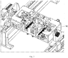
- Fig. 2 is a perspective view illustrating an outer appearance of an overall configuration of an end plate welding device constituting an apparatus for manufacturing a secondary battery
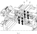
- Fig. 3 is a perspective view illustrating an upper cylinder of a top surface pressing portion constituting the end plate welding device
- Figs. 4 and 5 are perspective views of an end plate pressing portion constituting the end plate welding device
- Figs. 6 and 7 are perspective views of a side surface pressing portion constituting the end plate welding device.
- an end plate welding device 10 constituting an apparatus for manufacturing a secondary battery according to an embodiment may be understood as a device configured to weld and couple an end plate to both side surfaces of a mono frame, in which a cell module is accommodated.
- the end plate welding device 10 may include a module rotation unit 11.
- the module rotation unit 11 may include a housing 111 accommodating an assembly of a mono frame 22 and an end plate 23 before welding, a pair of rotation shafts 112 provided on both side surfaces of the housing 111, a servo motor 113 coupled to any one of the pair of rotation shafts 112, and a reducer 114 disposed between the servo motor 113 and the rotation shaft 112.
- the servo motor 113 and the reducer 114 may be defined as housing rotation units.
- the housing 111 may be constituted by a bottom portion, a top surface portion, a front portion, a rear portion, a left surface portion, and a right surface portion.
- the servo motor 113 and the speed reducer 114 may be connected to the rotation shaft 112 extending from any one of the left surface portion and the right surface portion of the housing 111.
- the reducer 114 may be a unit that reduces rotational force of the servo motor 113 and may include a hollow type reducer. As the hollow type reducer 114 is applied, there is no backlash, and thus, the rotational position is constant.
- the end plate welding device 10 may further include a housing support 15 supporting the pair of rotation shafts 112.
- the rotation shaft 112 is capable of linearly reciprocating on a horizontal plane along a top surface of the housing 15.
- the end plate welding device 10 may further include a top surface pressing portion 12.
- the top surface pressing portion 12 may include a pair of upper pushers 121, which are respectively disposed on upper portions of a front end and a rear end of the housing 111 in the drawing, and an upper cylinder 122 that rotates the upper pushers 121.
- Each of the pair of upper pushers 121 is rotatable at an angle of about 90 degrees or less in a horizontal state by an operation of the upper cylinder 122.
- the pair of upper pushers 121 press the top surface of the mono frame 22 to prevent the mono frame 22 from being shaken.
- the pair of upper cylinders 122 are coupled to the inside of the housing 111 to rotate together with the housing 111.
- the end plate welding device 10 may further include an end plate pressing portion 13.
- the end plate 23 is fitted into both side surfaces of the mono frame 22 and accommodated inside the housing 111 while being maintained in coupling force so as not be separated from both the side surfaces of the mono frame 22.
- the end plate pressing portion 13 performs a function of supporting the end plate 23 so as not to be separated from the mono frame 22.
- the end plate pressing portion 13 includes a module clamp 131 moving in a direction perpendicular to the end plate 23 and a module clamp driving cylinder 132 that linearly reciprocates the module clamp 132.
- the module clamp driving cylinder 132 is coupled to left and right sides of the housing 111 and linearly moves the module clamp 131 in a direction closer to and away from the end plate 23.
- the module clamp 131 is moved a predetermined distance from both sides of the mono frame 22 toward a center of the mono frame 22 so that the end plate 23 is stably coupled to both the side surface of the mono frame 22.
- a stopper is provided to restrict a distance by which the module clamp 131 is moved in the central direction of the mono frame 22 to support the end plate 23 to prevent the cell module 21 accommodated inside the mono frame 22 from being changed in position. That is, there is an advantage that the cell module 21 is not eccentric by being pushed to either side inside the mono frame 22.
- end plate welding device 10 may further include a side surface pressing portion 14.
- the side surface pressing portion 14 includes a pair of side clamps 141 that presses and supports the front and rear surfaces of the mono frame 22 and a pair of side clamp driving cylinder that drives the pair of side clamps 141.
- the pair of side clamps 141 are in close contact with the front and rear surfaces of the mono frame 22, respectively, to prevent the mono frame 22 from being shaken.
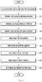
- Fig. 8 is a flowchart illustrating a process of welding an end plate during a method for manufacturing a secondary battery according to an embodiment.
- a secondary battery unit including a mono frame 22, in which a cell module 21 is accommodated, and an end plate 23 temporarily fixed to each of both side surfaces of the mono frame 22 are accommodated in a housing 111 of the end plate welding device (S11).
- a top surface pressing portion 12 operates to press a top surface of the mono frame 22 (S12). That is, an upper cylinder 122 operates to rotate an upper pusher 121, and the upper pusher 121 rotates in a horizontal state to press front and rear ends of the top surface of the mono frame 22.
- the end plate pressing portion 13 operates to press and support the end plate 23. That is, a module clamp driving cylinder 132 operates so that the end plate 23, on which the module clamp 131 is erected in a vertical state, is maintained in a state of being coupled to both the side surfaces of the mono frame 22. Then, a contact portion between the end plate 23 and the mono frame 22, i.e., a welded portion is prevented from being separated or twisted.
- the side surface pressing portion operates to press front and rear surfaces of the mono frame 22 (S14). That is, the side clamp driving cylinder 142 operates so that the side clamp 141 presses and supports the front and rear surfaces of the mono frame 22.
- the mono frame 22 and the end plate 23 may be maintained in a fixed state without being shaken within the housing 111, and also, the housing 111, the mono frame 22, and the end plate 23 may rotate as one body.
- an order of operation of the top surface pressing portion 12, the end plate pressing portion 13, and the side surface pressing portion 14 is not limited to the above sequence.
- a laser welding machine welds a welding portion at one side of the left and right edges of the top surface of the mono frame 22 and then welds a welding portion at the other side.
- the module rotation unit 11 When the welding of the top surface is finished, the module rotation unit 11 operates to rotate the housing 111 at an angle of about 180 degrees and then performs welding of an edge of a bottom surface of the secondary battery unit (S16). That is, when a servo motor 113 and a reducer 114 operate so that the housing 111 rotates at a predetermined rate about a rotation shaft 112, the bottom surface of the secondary battery unit moves to an upper side.
- the laser welding machine welds a welding portion at one side of the left and right edges of the bottom surface of the mono frame 22 and then welds a welding portion at the other side.
- the module rotation unit 11 operates to rotate the housing 111 at an angle of about 90 degrees so that an edge of the left surface (or an edge of the front surface) of the secondary battery unit is welded (S17).
- the module rotation unit 11 operates to rotate the housing 111 at an angle of about 180 degrees so that an edge of the left surface (or an edge of the front surface) of secondary battery unit is welded.
- the secondary battery unit is withdrawn to be transferred to a next manufacturing process (S19).
- the module rotation unit 11 rotates the housing 111 at an angle of about 90 degrees.
- the position of the cell module accommodated in the mono frame may be fixed.
- the housing rotates to prevent the mono frame from being twisted, the welding quality may be secured.
Landscapes
- Chemical & Material Sciences (AREA)
- Chemical Kinetics & Catalysis (AREA)
- Electrochemistry (AREA)
- General Chemical & Material Sciences (AREA)
- Engineering & Computer Science (AREA)
- Physics & Mathematics (AREA)
- Optics & Photonics (AREA)
- Manufacturing & Machinery (AREA)
- Plasma & Fusion (AREA)
- Mechanical Engineering (AREA)
- Sealing Battery Cases Or Jackets (AREA)
- Battery Mounting, Suspending (AREA)
Abstract
Description
- The present application claims priority to
Korean Patent Application No. 2021-0005560 filed on January 14, 2021 - The present disclosure relates to an apparatus and method for manufacturing a secondary battery.
- A main process for manufacturing a secondary battery may include a cell stacking process of stacking a plurality of cells to manufacture one module, a bus bar assembly process of electrically connecting copper to aluminum, a lead welding process of performing welding by using a laser to fix copper and aluminum to a bus bar, a module insertion process of inserting the module into a hexahedral mono frame to protect the module, and an end plate welding of sealing the mono frame using the laser so that foreign substances are not introduced into the module.
-
Fig. 1 is a perspective view illustrating an outer appearance of a secondary battery unit into which a cell module is inserted into a mono frame. - Referring to
FIG. 1 , acell module 21 on which in a lead welding process is performed has both opened side surfaces and is inserted into a hexahedralmono frame 22 having an opened inside. Thecell module 21 may be understood to mean a secondary battery in which a positive electrode lead and a negative electrode lead are attached to both ends of each of a plurality of stacked cells. - In addition, in a state in which the cell module is inserted into the
mono frame 22, both opened side surfaces of themono frame 22 are shielded by a rectangular plate that is called anend plate 23. - Also, an edge of the
end plate 23 and an edge portion of themono frame 22, that is, a contact portion W between theend plate 23 and themono frame 22 is welded using a laser. A secondary battery product, in which the welding process is completed, may be defined as asecondary battery unit 20. - When a material called a battery management system (BMS) is attached to the
secondary battery unit 20, the secondary battery product may be defined as a battery pack or a secondary battery pack. That is, thesecondary battery unit 20 may be understood as a product before the BMS is attached. - A welding device used to weld the
end plate 23 to both side surfaces of themono frame 22 performs welding while theend plate 23 is fitted into both ends of themono frame 22. Furthermore, a jig or clamp member constituting the welding device welds four edges of the end plate while rotating in a state of holding only theend plate 23. - As a result, when the
end plate 23 rotates to weld one edge and the other side of the end plate, a phenomenon in which a position of the end plate is shifted may occur. - In detail, if rotational rates of the pair of clamp members for respectively rotating the
end plates 23 that are in close contact with both side surfaces of themono frame 22 are not exactly the same, themono frame 22 may be twisted to allow an adhesive surface to be spread or changed in position. - As described above, when the positional shift phenomenon occurs, the welding may not be properly performed to cause a welding defect. As a result, there is a limitation in that sealing inside the
secondary battery unit 20 is not reliably performed. - The present invention has been proposed to improve the above-described limitations. The invention is defined in the claims.
- In one embodiment, an apparatus for manufacturing a secondary battery includes: a housing, in which a secondary battery unit including a cell module, a mono frame, into which the cell module is accommodated, and an end plate coupled to both opened side surfaces of the mono frame is accommodated; a pair of rotation shafts extending from both side surfaces of the housing; a housing rotation unit connected to any one of the pair of rotation shafts; a housing support configured to support the pair of rotation shafts; and a support unit provided inside the housing rotation unit to press and support the secondary battery unit.
- In another embodiment, a method for manufacturing a secondary battery includes: a first process of accommodating a secondary battery unit, which includes a cell module, a mono frame, into which the cell module is accommodated, and an end plate coupled to both opened side surfaces of the mono frame, into a housing; a second process of operating an end plate support unit to fix and support the mono frame and the end plate; and a third process of rotating the housing at an angle of about 90 degrees or about 180 degrees to weld a welding portion formed on a contact portion between the end plate and the mono frame.
- The details of one or more embodiments are set forth in the accompanying drawings and the description below. Other features will be apparent from the description and drawings, and from the claims.
-
-
Fig. 1 is a perspective view illustrating an outer appearance of a secondary battery unit into which a cell module is inserted into a mono frame. -
Fig. 2 is a perspective view illustrating an outer appearance of an overall configuration of an end plate welding device constituting an apparatus for manufacturing a secondary battery. -
Fig. 3 is a perspective view illustrating an upper cylinder of a top surface pressing portion constituting the end plate welding device. -
Figs. 4 and5 are perspective views of an end plate pressing portion constituting the end plate welding device. -
Figs. 6 and7 are perspective views of a side surface pressing portion constituting the end plate welding device. -
Fig. 8 is a flowchart illustrating a process of welding an end plate during a method for manufacturing a secondary battery according to an embodiment. - Hereinafter, an apparatus and method for manufacturing a secondary battery according to an embodiment will be described with reference to the drawings.
-
Fig. 2 is a perspective view illustrating an outer appearance of an overall configuration of an end plate welding device constituting an apparatus for manufacturing a secondary battery,Fig. 3 is a perspective view illustrating an upper cylinder of a top surface pressing portion constituting the end plate welding device,Figs. 4 and5 are perspective views of an end plate pressing portion constituting the end plate welding device, andFigs. 6 and7 are perspective views of a side surface pressing portion constituting the end plate welding device. - Referring to
Figs. 2 to 7 , an endplate welding device 10 constituting an apparatus for manufacturing a secondary battery according to an embodiment may be understood as a device configured to weld and couple an end plate to both side surfaces of a mono frame, in which a cell module is accommodated. - In detail, the end
plate welding device 10 may include amodule rotation unit 11. - The
module rotation unit 11 may include ahousing 111 accommodating an assembly of amono frame 22 and anend plate 23 before welding, a pair ofrotation shafts 112 provided on both side surfaces of thehousing 111, aservo motor 113 coupled to any one of the pair ofrotation shafts 112, and areducer 114 disposed between theservo motor 113 and therotation shaft 112. - The
servo motor 113 and thereducer 114 may be defined as housing rotation units. - The
housing 111 may be constituted by a bottom portion, a top surface portion, a front portion, a rear portion, a left surface portion, and a right surface portion. - The
servo motor 113 and thespeed reducer 114 may be connected to therotation shaft 112 extending from any one of the left surface portion and the right surface portion of thehousing 111. - The
reducer 114 may be a unit that reduces rotational force of theservo motor 113 and may include a hollow type reducer. As thehollow type reducer 114 is applied, there is no backlash, and thus, the rotational position is constant. - In addition, it should be noted that other types of motors other than the
servo motor 113 may also be applied. - The end
plate welding device 10 may further include ahousing support 15 supporting the pair ofrotation shafts 112. Therotation shaft 112 is capable of linearly reciprocating on a horizontal plane along a top surface of thehousing 15. - The end
plate welding device 10 may further include a topsurface pressing portion 12. - The top
surface pressing portion 12 may include a pair ofupper pushers 121, which are respectively disposed on upper portions of a front end and a rear end of thehousing 111 in the drawing, and anupper cylinder 122 that rotates theupper pushers 121. - Each of the pair of
upper pushers 121 is rotatable at an angle of about 90 degrees or less in a horizontal state by an operation of theupper cylinder 122. Thus, in the state in which themono frame 22 is accommodated in thehousing 111, the pair ofupper pushers 121 press the top surface of themono frame 22 to prevent themono frame 22 from being shaken. - The pair of
upper cylinders 122 are coupled to the inside of thehousing 111 to rotate together with thehousing 111. - The end
plate welding device 10 may further include an endplate pressing portion 13. - In detail, before the
end plate 23 is welded to themono frame 22, theend plate 23 is fitted into both side surfaces of themono frame 22 and accommodated inside thehousing 111 while being maintained in coupling force so as not be separated from both the side surfaces of themono frame 22. - The end
plate pressing portion 13 performs a function of supporting theend plate 23 so as not to be separated from themono frame 22. - The end
plate pressing portion 13 includes amodule clamp 131 moving in a direction perpendicular to theend plate 23 and a moduleclamp driving cylinder 132 that linearly reciprocates themodule clamp 132. - The module
clamp driving cylinder 132 is coupled to left and right sides of thehousing 111 and linearly moves themodule clamp 131 in a direction closer to and away from theend plate 23. - The
module clamp 131 is moved a predetermined distance from both sides of themono frame 22 toward a center of themono frame 22 so that theend plate 23 is stably coupled to both the side surface of themono frame 22. - In addition, a stopper is provided to restrict a distance by which the
module clamp 131 is moved in the central direction of themono frame 22 to support theend plate 23 to prevent thecell module 21 accommodated inside themono frame 22 from being changed in position. That is, there is an advantage that thecell module 21 is not eccentric by being pushed to either side inside themono frame 22. - In addition, the end
plate welding device 10 may further include a sidesurface pressing portion 14. - The side
surface pressing portion 14 includes a pair ofside clamps 141 that presses and supports the front and rear surfaces of themono frame 22 and a pair of side clamp driving cylinder that drives the pair ofside clamps 141. - When the side
clamp driving cylinder 142 operates, the pair ofside clamps 141 are in close contact with the front and rear surfaces of themono frame 22, respectively, to prevent themono frame 22 from being shaken. - Hereinafter, an end plate welding method performed in the end
plate welding device 10 will be described. The welding method will be described by limiting that laser welding is applied. -
Fig. 8 is a flowchart illustrating a process of welding an end plate during a method for manufacturing a secondary battery according to an embodiment. - Referring to
Fig. 8 , first, a secondary battery unit including amono frame 22, in which acell module 21 is accommodated, and anend plate 23 temporarily fixed to each of both side surfaces of themono frame 22 are accommodated in ahousing 111 of the end plate welding device (S11). - In this state, a top
surface pressing portion 12 operates to press a top surface of the mono frame 22 (S12). That is, anupper cylinder 122 operates to rotate anupper pusher 121, and theupper pusher 121 rotates in a horizontal state to press front and rear ends of the top surface of themono frame 22. - Then, the end
plate pressing portion 13 operates to press and support theend plate 23. That is, a moduleclamp driving cylinder 132 operates so that theend plate 23, on which themodule clamp 131 is erected in a vertical state, is maintained in a state of being coupled to both the side surfaces of themono frame 22. Then, a contact portion between theend plate 23 and themono frame 22, i.e., a welded portion is prevented from being separated or twisted. - Then, the side surface pressing portion operates to press front and rear surfaces of the mono frame 22 (S14). That is, the side
clamp driving cylinder 142 operates so that theside clamp 141 presses and supports the front and rear surfaces of themono frame 22. - When all of the above processes are performed, the
mono frame 22 and theend plate 23 may be maintained in a fixed state without being shaken within thehousing 111, and also, thehousing 111, themono frame 22, and theend plate 23 may rotate as one body. - Here, an order of operation of the top
surface pressing portion 12, the endplate pressing portion 13, and the sidesurface pressing portion 14 is not limited to the above sequence. - When an assembly of the
cell module 21, themono frame 22, and theend plate 23, i.e., the secondary battery unit is fixed in thehousing 111, an edge of the top surface of themono frame 22 is welded (S15). In detail, a laser welding machine welds a welding portion at one side of the left and right edges of the top surface of themono frame 22 and then welds a welding portion at the other side. - When the welding of the top surface is finished, the
module rotation unit 11 operates to rotate thehousing 111 at an angle of about 180 degrees and then performs welding of an edge of a bottom surface of the secondary battery unit (S16). That is, when aservo motor 113 and areducer 114 operate so that thehousing 111 rotates at a predetermined rate about arotation shaft 112, the bottom surface of the secondary battery unit moves to an upper side. - In this state, the laser welding machine welds a welding portion at one side of the left and right edges of the bottom surface of the
mono frame 22 and then welds a welding portion at the other side. - When the welding of the bottom surface is finished, the
module rotation unit 11 operates to rotate thehousing 111 at an angle of about 90 degrees so that an edge of the left surface (or an edge of the front surface) of the secondary battery unit is welded (S17). - When the welding of the left surface is finished, the
module rotation unit 11 operates to rotate thehousing 111 at an angle of about 180 degrees so that an edge of the left surface (or an edge of the front surface) of secondary battery unit is welded. - When the welding of the edge of the right surface is finished, the secondary battery unit is withdrawn to be transferred to a next manufacturing process (S19).
- Here, it should be noted that the order of the welding from the edge of the top surface to the edge of the right surface is not limited to the above description sequence.
- For example, after the welding of the edge of the top surface is finished, it may be possible to sequentially weld the front surface, the bottom surface, and the rear side in the order while the
module rotation unit 11 rotates thehousing 111 at an angle of about 90 degrees. - According to the apparatus and method for manufacturing the secondary battery according to the embodiment, since the housing that accommodates the secondary battery unit rotates in the state in which the six surfaces of the secondary battery unit are fixed and supported, the position of the cell module accommodated in the mono frame may be fixed.
- In addition, since the housing rotates to prevent the mono frame from being twisted, the welding quality may be secured.
- In addition, since the hollow type reducer is used, there may be no backlash, and thus, the rotational position may be constant.
Claims (15)
- An apparatus for manufacturing a secondary battery, the apparatus comprising:a housing, in which a secondary battery unit comprising a cell module, a mono frame, into which the cell module is accommodated, and an end plate coupled to both opened side surfaces of the mono frame is accommodated;a pair of rotation shafts extending from both side surfaces of the housing;a housing rotation unit connected to any one of the pair of rotation shafts;a housing support configured to support the pair of rotation shafts; anda support unit provided inside the housing rotation unit to press and support the secondary battery unit.
- The apparatus according to claim 1, wherein the support unit comprises a pair of top surface pressing portions that are respectively provided at front and rear sides of the housing to press a top surface of the mono frame.
- The apparatus according to claim 2, wherein each of the pair of top surface pressing portions comprises:an upper cylinder; andan upper pusher rotatably connected to the upper cylinder to press the top surface of the mono frame.
- The apparatus according to claim 2, or 3, wherein the support unit comprises a pair of end plate pressing portions that are respectively provided at both sides of the housing to press and support the end plate.
- The apparatus according to claim 4, wherein each of the pair of end plate pressing portions comprise:a module clamp configured to press each of the pair of end plates; anda module clamp driving cylinder configured to move the module clamp horizontally in a central direction of the mono frame.
- The apparatus according to claim 4, or 5, wherein the support unit comprises a pair of top surface pressing portions that are respectively provided at front and rear sides of the housing to press and support front and rear surfaces of the mono frame.
- The apparatus according to claim 6, wherein each of the pair of side surface pressing portion comprises:a side clamp configured to press and support the front or rear surfaces of the mono frame; anda side clamp driving cylinder configured to moves the side clamp horizontally in a central direction of the mono frame.
- The apparatus according to claim 6, wherein the housing rotation unit comprises:a servo motor; anda reducer configured to connect the servo motor to the rotation shaft and reduce rotation force of the servo motor.
- The apparatus according to claim 8, wherein the reducer comprises a hollow type reducer.
- A method for manufacturing a secondary battery, the method comprising:a first process of accommodating a secondary battery unit, which comprises a cell module, a mono frame, into which the cell module is accommodated, and an end plate coupled to both opened side surfaces of the mono frame, into a housing;a second process of operating an end plate support unit to fix and support the mono frame and the end plate; anda third process of rotating the housing at an angle of about 90 degrees or about 180 degrees to weld a welding portion formed on a contact portion between the end plate and the mono frame.
- The method according to claim 10, wherein the second process comprises operating a top surface pressing portion configured to press a top surface of the mono frame, an end plate pressing portion configured to press the end plate, and a side surface pressing portion configured to press front and rear surfaces of the mono frame.
- The method according to claim 11, wherein the top surface pressing portion, the end plate pressing portion, and the side surface pressing portion are operated at the same time or in order to support the mono frame and the end plate.
- The method according to claim 11, or 12, wherein the third process comprises:welding an edge of a top surface of the mono frame;rotating the housing at an angle of about 180 degrees to weld an edge of a bottom surface of the mono frame;rotating the housing at an angle of about 90 degrees to weld an edge of a front surface of the mono frame; androtating the housing at an angle of about 180 degrees to weld an edge of a rear surface of the mono frame.
- The method according to claim 11, 12, or 13, wherein the third process comprises:welding an edge of a top surface of the mono frame;rotating the housing at an angle of about 90 degrees to weld an edge of a rear surface of the mono frame;rotating the housing at an angle of about 90 degrees to weld an edge of a bottom surface of the mono frame; androtating the housing at an angle of about 90 degrees to weld an edge of a front surface of the mono frame.
- The method according to claim 11, wherein the welding performed in the third process comprises laser welding.
Applications Claiming Priority (1)
| Application Number | Priority Date | Filing Date | Title |
|---|---|---|---|
| KR1020210005560A KR20220102971A (en) | 2021-01-14 | 2021-01-14 | Apparatus and method for manufacturing secondary cell |
Publications (1)
| Publication Number | Publication Date |
|---|---|
| EP4030543A1 true EP4030543A1 (en) | 2022-07-20 |
Family
ID=79185444
Family Applications (1)
| Application Number | Title | Priority Date | Filing Date |
|---|---|---|---|
| EP21218278.6A Pending EP4030543A1 (en) | 2021-01-14 | 2021-12-30 | Apparatus and method for manufacturing secondary battery |
Country Status (3)
| Country | Link |
|---|---|
| EP (1) | EP4030543A1 (en) |
| KR (1) | KR20220102971A (en) |
| WO (1) | WO2022154296A1 (en) |
Cited By (1)
| Publication number | Priority date | Publication date | Assignee | Title |
|---|---|---|---|---|
| CN116038119A (en) * | 2023-02-06 | 2023-05-02 | 苏州锐方激光科技有限公司 | Soft packet of battery welding equipment |
Families Citing this family (1)
| Publication number | Priority date | Publication date | Assignee | Title |
|---|---|---|---|---|
| KR102633316B1 (en) * | 2023-09-07 | 2024-02-05 | (주)케이엔에스 | Welding apparatus for prismatic type secondary battery can |
Citations (2)
| Publication number | Priority date | Publication date | Assignee | Title |
|---|---|---|---|---|
| CN108772650A (en) * | 2018-06-28 | 2018-11-09 | 苏州巨智能装备有限公司 | Battery core module side panel welds accurate positioning device, welding robot and its welding method |
| KR20200123708A (en) * | 2019-04-22 | 2020-10-30 | (주)휴민텍 | Jig device for frame welder |
Family Cites Families (4)
| Publication number | Priority date | Publication date | Assignee | Title |
|---|---|---|---|---|
| JP6024092B2 (en) * | 2011-10-26 | 2016-11-09 | 株式会社Gsユアサ | Metal container manufacturing method, metal container, power storage element, and power storage module |
| KR102315847B1 (en) * | 2018-10-05 | 2021-10-21 | 주식회사 엘지에너지솔루션 | Battery Pack Comprising Battery Pack Frame Capable of Preventing Welding Defect and Pressing Jig for Preparing the Same |
| KR102694746B1 (en) * | 2019-01-10 | 2024-08-12 | 주식회사 엘지에너지솔루션 | Method for Preparing Battery Pack |
| KR102071350B1 (en) * | 2019-08-06 | 2020-01-30 | (주)대흥정밀산업 | Welding machine equipped with a jig for welding a lid to a metal container containing contents |
-
2021
- 2021-01-14 KR KR1020210005560A patent/KR20220102971A/en not_active Withdrawn
- 2021-12-22 WO PCT/KR2021/019580 patent/WO2022154296A1/en not_active Ceased
- 2021-12-30 EP EP21218278.6A patent/EP4030543A1/en active Pending
Patent Citations (2)
| Publication number | Priority date | Publication date | Assignee | Title |
|---|---|---|---|---|
| CN108772650A (en) * | 2018-06-28 | 2018-11-09 | 苏州巨智能装备有限公司 | Battery core module side panel welds accurate positioning device, welding robot and its welding method |
| KR20200123708A (en) * | 2019-04-22 | 2020-10-30 | (주)휴민텍 | Jig device for frame welder |
Cited By (1)
| Publication number | Priority date | Publication date | Assignee | Title |
|---|---|---|---|---|
| CN116038119A (en) * | 2023-02-06 | 2023-05-02 | 苏州锐方激光科技有限公司 | Soft packet of battery welding equipment |
Also Published As
| Publication number | Publication date |
|---|---|
| KR20220102971A (en) | 2022-07-21 |
| WO2022154296A1 (en) | 2022-07-21 |
Similar Documents
| Publication | Publication Date | Title |
|---|---|---|
| EP4030543A1 (en) | Apparatus and method for manufacturing secondary battery | |
| CN203085688U (en) | Secondary battery and secondary battery manufacturing device | |
| US10553840B2 (en) | Manufacturing method and manufacturing device for battery pack | |
| KR102255705B1 (en) | Cell lamination and thermocompression bonding device, and cell lamination and thermocompression bonding method | |
| US20230150072A1 (en) | Automatic pressure jig device for bringing electrode lead into close contact with busbar, and battery module manufacturing system comprising same | |
| EP3367470B1 (en) | Battery pack and method for producing battery pack | |
| EP3836252A1 (en) | Pressure jig apparatus for bringing electrode lead into close contact with bus bar and battery module manufacturing system including same | |
| KR102439235B1 (en) | Multi-cell tap cutting device and method | |
| KR102212849B1 (en) | Jig device for frame welder | |
| US20190372079A1 (en) | Battery pack production method and production device | |
| CN116551593B (en) | clamps | |
| KR102539546B1 (en) | Prismatic type secondary battery Z-folding apparatus and Z-folding method thereby | |
| WO2022227557A1 (en) | Jig and assembly device | |
| CN119383942A (en) | A PCBA board assembly production line for TCU controller | |
| CN113182736B (en) | Full-automatic welding device for connector | |
| US20240222678A1 (en) | Production device for resin framed electrode foil | |
| CN215036657U (en) | Battery module fixing tool | |
| KR20030014260A (en) | Sleeve separator and device for producing the same | |
| CN110270751B (en) | Welding device and welding method | |
| EP4249189A1 (en) | Apparatus for inserting electrode assembly and method for inserting electrode assembly using same | |
| CN218706962U (en) | Material loading turning device | |
| CN217807323U (en) | Loading and unloading device and loading and unloading system comprising same | |
| CN214588940U (en) | Lamination device | |
| CN221952609U (en) | Module welding equipment | |
| CN222530467U (en) | Packaging device for battery packaging and automatic packaging equipment |
Legal Events
| Date | Code | Title | Description |
|---|---|---|---|
| PUAI | Public reference made under article 153(3) epc to a published international application that has entered the european phase |
Free format text: ORIGINAL CODE: 0009012 |
|
| STAA | Information on the status of an ep patent application or granted ep patent |
Free format text: STATUS: THE APPLICATION HAS BEEN PUBLISHED |
|
| AK | Designated contracting states |
Kind code of ref document: A1 Designated state(s): AL AT BE BG CH CY CZ DE DK EE ES FI FR GB GR HR HU IE IS IT LI LT LU LV MC MK MT NL NO PL PT RO RS SE SI SK SM TR |
|
| STAA | Information on the status of an ep patent application or granted ep patent |
Free format text: STATUS: REQUEST FOR EXAMINATION WAS MADE |
|
| 17P | Request for examination filed |
Effective date: 20230117 |
|
| RBV | Designated contracting states (corrected) |
Designated state(s): AL AT BE BG CH CY CZ DE DK EE ES FI FR GB GR HR HU IE IS IT LI LT LU LV MC MK MT NL NO PL PT RO RS SE SI SK SM TR |
|
| STAA | Information on the status of an ep patent application or granted ep patent |
Free format text: STATUS: EXAMINATION IS IN PROGRESS |
|
| 17Q | First examination report despatched |
Effective date: 20241210 |