EP4030105B1 - Aircraft oven with a hydrophobic filter in oven air outlet - Google Patents
Aircraft oven with a hydrophobic filter in oven air outlet Download PDFInfo
- Publication number
- EP4030105B1 EP4030105B1 EP21217538.4A EP21217538A EP4030105B1 EP 4030105 B1 EP4030105 B1 EP 4030105B1 EP 21217538 A EP21217538 A EP 21217538A EP 4030105 B1 EP4030105 B1 EP 4030105B1
- Authority
- EP
- European Patent Office
- Prior art keywords
- oven
- drain
- fluid
- conduit
- recited
- Prior art date
- Legal status (The legal status is an assumption and is not a legal conclusion. Google has not performed a legal analysis and makes no representation as to the accuracy of the status listed.)
- Active
Links
Images
Classifications
-
- F—MECHANICAL ENGINEERING; LIGHTING; HEATING; WEAPONS; BLASTING
- F24—HEATING; RANGES; VENTILATING
- F24C—DOMESTIC STOVES OR RANGES ; DETAILS OF DOMESTIC STOVES OR RANGES, OF GENERAL APPLICATION
- F24C15/00—Details
- F24C15/20—Removing cooking fumes
- F24C15/2035—Arrangement or mounting of filters
-
- F—MECHANICAL ENGINEERING; LIGHTING; HEATING; WEAPONS; BLASTING
- F24—HEATING; RANGES; VENTILATING
- F24C—DOMESTIC STOVES OR RANGES ; DETAILS OF DOMESTIC STOVES OR RANGES, OF GENERAL APPLICATION
- F24C15/00—Details
- F24C15/20—Removing cooking fumes
- F24C15/2007—Removing cooking fumes from oven cavities
-
- A—HUMAN NECESSITIES
- A47—FURNITURE; DOMESTIC ARTICLES OR APPLIANCES; COFFEE MILLS; SPICE MILLS; SUCTION CLEANERS IN GENERAL
- A47J—KITCHEN EQUIPMENT; COFFEE MILLS; SPICE MILLS; APPARATUS FOR MAKING BEVERAGES
- A47J27/00—Cooking-vessels
- A47J27/04—Cooking-vessels for cooking food in steam; Devices for extracting fruit juice by means of steam ; Vacuum cooking vessels
-
- B—PERFORMING OPERATIONS; TRANSPORTING
- B01—PHYSICAL OR CHEMICAL PROCESSES OR APPARATUS IN GENERAL
- B01D—SEPARATION
- B01D39/00—Filtering material for liquid or gaseous fluids
- B01D39/08—Filter cloth, i.e. woven, knitted or interlaced material
-
- B—PERFORMING OPERATIONS; TRANSPORTING
- B01—PHYSICAL OR CHEMICAL PROCESSES OR APPARATUS IN GENERAL
- B01D—SEPARATION
- B01D46/00—Filters or filtering processes specially modified for separating dispersed particles from gases or vapours
- B01D46/0027—Filters or filtering processes specially modified for separating dispersed particles from gases or vapours with additional separating or treating functions
- B01D46/003—Filters or filtering processes specially modified for separating dispersed particles from gases or vapours with additional separating or treating functions including coalescing means for the separation of liquid
- B01D46/0031—Filters or filtering processes specially modified for separating dispersed particles from gases or vapours with additional separating or treating functions including coalescing means for the separation of liquid with collecting, draining means
-
- B—PERFORMING OPERATIONS; TRANSPORTING
- B01—PHYSICAL OR CHEMICAL PROCESSES OR APPARATUS IN GENERAL
- B01D—SEPARATION
- B01D53/00—Separation of gases or vapours; Recovering vapours of volatile solvents from gases; Chemical or biological purification of waste gases, e.g. engine exhaust gases, smoke, fumes, flue gases, aerosols
- B01D53/26—Drying gases or vapours
- B01D53/266—Drying gases or vapours by filtration
-
- F—MECHANICAL ENGINEERING; LIGHTING; HEATING; WEAPONS; BLASTING
- F24—HEATING; RANGES; VENTILATING
- F24C—DOMESTIC STOVES OR RANGES ; DETAILS OF DOMESTIC STOVES OR RANGES, OF GENERAL APPLICATION
- F24C15/00—Details
- F24C15/003—Details moisturising of air
-
- F—MECHANICAL ENGINEERING; LIGHTING; HEATING; WEAPONS; BLASTING
- F24—HEATING; RANGES; VENTILATING
- F24C—DOMESTIC STOVES OR RANGES ; DETAILS OF DOMESTIC STOVES OR RANGES, OF GENERAL APPLICATION
- F24C15/00—Details
- F24C15/14—Spillage trays or grooves
-
- A—HUMAN NECESSITIES
- A47—FURNITURE; DOMESTIC ARTICLES OR APPLIANCES; COFFEE MILLS; SPICE MILLS; SUCTION CLEANERS IN GENERAL
- A47J—KITCHEN EQUIPMENT; COFFEE MILLS; SPICE MILLS; APPARATUS FOR MAKING BEVERAGES
- A47J27/00—Cooking-vessels
- A47J27/04—Cooking-vessels for cooking food in steam; Devices for extracting fruit juice by means of steam ; Vacuum cooking vessels
- A47J2027/043—Cooking-vessels for cooking food in steam; Devices for extracting fruit juice by means of steam ; Vacuum cooking vessels for cooking food in steam
-
- B—PERFORMING OPERATIONS; TRANSPORTING
- B01—PHYSICAL OR CHEMICAL PROCESSES OR APPARATUS IN GENERAL
- B01D—SEPARATION
- B01D2239/00—Aspects relating to filtering material for liquid or gaseous fluids
- B01D2239/04—Additives and treatments of the filtering material
- B01D2239/0414—Surface modifiers, e.g. comprising ion exchange groups
- B01D2239/0428—Rendering the filter material hydrophobic
-
- B—PERFORMING OPERATIONS; TRANSPORTING
- B64—AIRCRAFT; AVIATION; COSMONAUTICS
- B64D—EQUIPMENT FOR FITTING IN OR TO AIRCRAFT; FLIGHT SUITS; PARACHUTES; ARRANGEMENT OR MOUNTING OF POWER PLANTS OR PROPULSION TRANSMISSIONS IN AIRCRAFT
- B64D11/00—Passenger or crew accommodation; Flight-deck installations not otherwise provided for
- B64D11/04—Galleys
-
- F—MECHANICAL ENGINEERING; LIGHTING; HEATING; WEAPONS; BLASTING
- F24—HEATING; RANGES; VENTILATING
- F24C—DOMESTIC STOVES OR RANGES ; DETAILS OF DOMESTIC STOVES OR RANGES, OF GENERAL APPLICATION
- F24C15/00—Details
- F24C15/32—Arrangements of ducts for hot gases, e.g. in or around baking ovens
- F24C15/322—Arrangements of ducts for hot gases, e.g. in or around baking ovens with forced circulation
- F24C15/327—Arrangements of ducts for hot gases, e.g. in or around baking ovens with forced circulation with air moisturising
Definitions
- the present disclosure relates to aircraft ovens, and more particularly to air outlet filters in aircraft ovens.
- Modem ovens e.g. such as those used in aircraft galleys, have a condenser on the outlet of the oven to capture moisture from the exhaust air.
- the principle of a condenser is too cool down the exhaust air, so that the humidity in the air condenses to water, which can then be captured or recycled.
- the condensers used in modern ovens have poor efficiency to capture moisture, which if left unchecked can result in excessive moisture in the galley monument and effectively resulting in fungus growth.
- CN 111 956 056 A describes a water vapour separation mechanism.
- DE 10 2017 216744 A1 describes a method of removing moisture from air.
- WO 2004/104483 A1 describes an oven and its combination with a steam module.
- CN 208 876 051 U discloses a steam cooking oven comprising a steam generator communicating with a cooking cavity through an inlet pipe. The end of the inlet pipe comprises a non-woven filter net which intercepts liquid water from the water vapour coming from the steam generator.
- An oven is defined in claim 1 and comprises a cooking volume and a fluid inlet in fluid communication with the cooking volume for ingress of fluid into the cooking volume.
- the oven also comprises an outlet conduit in fluid communication with the cooking volume for egress of fluid from the cooking volume.
- the oven further includes a hydrophobic filter in the outlet conduit configured to capture moisture from a flow of fluid egressing from the cooking volume.
- the hydrophobic filter includes a fabric filter element of a hydrophobic material within a filter housing defining a filtration flow path therethrough. There can be no condenser in the outlet conduit.
- the hydrophobic filter can be configured to allow passage of fluid therethrough to an outlet of the outlet conduit, and to separate liquid water from the gas to a liquid water drain in fluid communication with the hydrophobic filter.
- the hydrophobic filter can also include a filter housing defined along a longitudinal axis oriented vertically.
- the filter housing can include PTFE.
- a drain can connect to a bottom portion of the filter housing for gravity driven flow of liquid water out of the filter housing.
- the drain can include a drain conduit that outlets to a heated surface of the oven for evaporation of liquid water from the drain to ambient surroundings of the oven.
- a fluid source can operatively connect to supply fluid to the fluid inlet for steam cooking.
- the oven may comprise a drain conduit comprising a conduit body with an inlet and an outlet with the hydrophobic filter between the conduit inlet and configured to capture moisture from a flow of fluid through the conduit body.
- the drain conduit can further include a recycle conduit in fluid communication with the cooking volume for recycled injection into the cooking volume.
- FIG. 1 a partial view of an embodiment of an oven in accordance with the disclosure is shown in Fig. 1 and is designated generally by reference character 100.
- FIGs. 2-3 Other embodiments of systems in accordance with the disclosure, or aspects thereof, are provided in Figs. 2-3 , as will be described.
- the systems and methods described herein can be used to improve moisture capture in an oven compartment.
- an oven 100 can include a cooking volume 102, where the cooking volume 102 can include at least one heating element 104 therein.
- the heating element 104 is shown in a top portion of the oven 100, however the heating element 104 can be mounted in a portion of the oven 100, or any suitable place within the oven 100. It is also possible that the oven 100 can have multiple heating elements 104, for example mounted in a top and bottom portion of the oven 100.
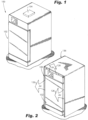
- the oven 100 can be included in a galley monument 136 as in Fig. 1 , or can be a standalone oven 100 as in Fig. 2 . Referring to Figs.
- the oven 100 can include a fluid inlet 106 in fluid communication with the cooking volume 102 for ingress of fluid into the cooking volume 102.
- the fluid inlet 106 can be in fluid communication with the cooking volume 102 and an external fluid source 110 via any suitable connection, such as conduit 108.
- the fluid source 110 can be operatively connected to the oven 100 to supply fluid (e.g. water) to the fluid inlet 106 for evaporation via heating element 104, and cooking within the cooking volume 102.
- the oven 100 can also include an outlet conduit 112 in fluid communication with the cooking volume 102 for egress of the evaporated fluid from the cooking volume 102.
- the oven 100 can include a hydrophobic filter 114 disposed in the outlet conduit 112 to capture moisture from the flow of fluid egressing from the cooking volume 102 as it flows through the outlet conduit 112.
- the hydrophobic filter 114 can include a fabric filter element 116 of a hydrophobic material, for example, the fabric filter element can be any suitable material that includes microstructures for hydrophobicity.
- the hydrophobic fabric filter element 116 will allow passage of gas (e.g. air or exhaust from the cooking volume 102) to an outlet 118 of the outlet conduit 112. When the fluid is passed through the fabric filter element 116, the liquid water can be separated from the gas, so the liquid water can then pass to a liquid water drain 120 in fluid communication with the hydrophobic filter 114.
- the hydrophobic filter 114 can be disposed within a filter housing 122 that defines a filtration flow path therethrough, for example as represented by arrow 124.
- the filter housing 122 defined along a longitudinal axis A oriented vertically relative to the direction of gravity so that captured moisture can flow downward through the filter 114.
- the filter housing 122 can include polytetrafluoroethylene (PTFE), any other suitable hydrophobic, heat resistant polymer, and/or any combination thereof.
- the system therefore can no longer require a condenser in the outlet conduit.
- the oven 100 can include no condenser anywhere in the line between the cooking volume 102 and a gas outlet 118 where gas is released from the outlet conduit 112 into ambient surroundings 126 of the oven.
- the liquid water drain 120 can connect to a bottom portion 130 of the filter housing 122 for collection and gravity driven flow of liquid water out of the filter housing 122.
- the drain 120 can also include a drain conduit 132 that outlets to a heated surface of the oven 100 for evaporation of liquid water from the drain 120 to ambient surroundings 126 of the oven 100, for example, the ambient surroundings 126 can include within a galley monument 136, and/or surrounding atmosphere outside the galley monument 136.
- the heated surface 134 may be the heating element 104 within the cooking volume 102 so the condensate may be reused used for cooking, or the heated surface 134 may be any number of and/or a combination of heated components within the system 100.
- the drain 120 could also recycle the collected water from the drain 120 to the steam supply 110, e.g. through recycle conduit 138, to be used for further injection into the cooking volume 102.
- the methods and systems of the present disclosure provide for improved capture of remaining moisture from an oven, reducing the amount of ambient moisture that can build in galley monument, preventing mold and fungal growth within the galley monument. Additionally, the galley walls can only withstand temperatures to a certain limit. If exhaust temperatures increase, there will be an increase the galley wall temperatures. The systems as described herein therefore provide for a reduction in galley wall temperatures, which can provide additional benefits to the oven system as a whole, e.g. faster and improved cooking performance. While the apparatus and methods of the subject disclosure have been shown and described, those skilled in the art will readily appreciate that changes and/or modifications may be made thereto without departing from the scope of the subject disclosure.
Landscapes
- Engineering & Computer Science (AREA)
- Chemical & Material Sciences (AREA)
- Combustion & Propulsion (AREA)
- General Engineering & Computer Science (AREA)
- Mechanical Engineering (AREA)
- Chemical Kinetics & Catalysis (AREA)
- General Chemical & Material Sciences (AREA)
- Oil, Petroleum & Natural Gas (AREA)
- Analytical Chemistry (AREA)
- Food Science & Technology (AREA)
- Textile Engineering (AREA)
- Filtering Of Dispersed Particles In Gases (AREA)
- Separation Using Semi-Permeable Membranes (AREA)
Description
- The present disclosure relates to aircraft ovens, and more particularly to air outlet filters in aircraft ovens.
- Modem ovens, e.g. such as those used in aircraft galleys, have a condenser on the outlet of the oven to capture moisture from the exhaust air. The principle of a condenser is too cool down the exhaust air, so that the humidity in the air condenses to water, which can then be captured or recycled. The condensers used in modern ovens have poor efficiency to capture moisture, which if left unchecked can result in excessive moisture in the galley monument and effectively resulting in fungus growth.
- The conventional techniques have been considered satisfactory for their intended purpose. However, there is an ever present need for improved systems and methods for more effective moisture capture in an oven air outlet. This disclosure provides a solution for this need.
CN 111 956 056 A describes a water vapour separation mechanism.DE 10 2017 216744 A1 describes a method of removing moisture from air.WO 2004/104483 A1 describes an oven and its combination with a steam module.CN 208 876 051 U discloses a steam cooking oven comprising a steam generator communicating with a cooking cavity through an inlet pipe. The end of the inlet pipe comprises a non-woven filter net which intercepts liquid water from the water vapour coming from the steam generator. - An oven is defined in claim 1 and comprises a cooking volume and a fluid inlet in fluid communication with the cooking volume for ingress of fluid into the cooking volume. The oven also comprises an outlet conduit in fluid communication with the cooking volume for egress of fluid from the cooking volume. The oven further includes a hydrophobic filter in the outlet conduit configured to capture moisture from a flow of fluid egressing from the cooking volume.
- The hydrophobic filter includes a fabric filter element of a hydrophobic material within a filter housing defining a filtration flow path therethrough. There can be no condenser in the outlet conduit. The hydrophobic filter can be configured to allow passage of fluid therethrough to an outlet of the outlet conduit, and to separate liquid water from the gas to a liquid water drain in fluid communication with the hydrophobic filter. The hydrophobic filter can also include a filter housing defined along a longitudinal axis oriented vertically. The filter housing can include PTFE.
- A drain can connect to a bottom portion of the filter housing for gravity driven flow of liquid water out of the filter housing. The drain can include a drain conduit that outlets to a heated surface of the oven for evaporation of liquid water from the drain to ambient surroundings of the oven. A fluid source can operatively connect to supply fluid to the fluid inlet for steam cooking.
- The oven may comprise a drain conduit comprising a conduit body with an inlet and an outlet with the hydrophobic filter between the conduit inlet and configured to capture moisture from a flow of fluid through the conduit body. The drain conduit can further include a recycle conduit in fluid communication with the cooking volume for recycled injection into the cooking volume.
- These and other features of the systems and methods of the subject disclosure will become more readily apparent to those skilled in the art from the following detailed description taken in conjunction with the drawings.
- So that those skilled in the art to which the subject disclosure appertains will readily understand how to make and use the devices and methods of the subject disclosure without undue experimentation, embodiments thereof will be described in detail herein below with reference to certain figures, wherein:
-
Fig. 1 is a schematic front perspective view of an embodiment of an oven constructed in accordance with the present disclosure, showing an oven in a galley monument; -
Fig. 2 is a schematic front perspective view of the oven ofFig. 1 outside a galley monument; -
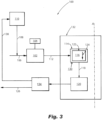
Fig. 3 is a schematic box diagram of the oven ofFigs. 1-2 , showing a flow path through the hydrophobic filter system in accordance with at least one aspect of this disclosure. - Reference will now be made to the drawings wherein like reference numerals identify similar structural features or aspects of the subject disclosure. For purposes of explanation and illustration, and not limitation, a partial view of an embodiment of an oven in accordance with the disclosure is shown in
Fig. 1 and is designated generally byreference character 100. Other embodiments of systems in accordance with the disclosure, or aspects thereof, are provided inFigs. 2-3 , as will be described. The systems and methods described herein can be used to improve moisture capture in an oven compartment. - Shown in
Figs. 1 and 2 , anoven 100 can include acooking volume 102, where thecooking volume 102 can include at least oneheating element 104 therein. InFig. 1 , theheating element 104 is shown in a top portion of theoven 100, however theheating element 104 can be mounted in a portion of theoven 100, or any suitable place within theoven 100. It is also possible that theoven 100 can havemultiple heating elements 104, for example mounted in a top and bottom portion of theoven 100. Theoven 100 can be included in agalley monument 136 as inFig. 1 , or can be astandalone oven 100 as inFig. 2 . Referring toFigs. 2-3 , theoven 100 can include afluid inlet 106 in fluid communication with thecooking volume 102 for ingress of fluid into thecooking volume 102. For example, thefluid inlet 106 can be in fluid communication with thecooking volume 102 and anexternal fluid source 110 via any suitable connection, such asconduit 108. Thefluid source 110 can be operatively connected to theoven 100 to supply fluid (e.g. water) to thefluid inlet 106 for evaporation viaheating element 104, and cooking within thecooking volume 102. Theoven 100 can also include anoutlet conduit 112 in fluid communication with thecooking volume 102 for egress of the evaporated fluid from thecooking volume 102. - The
oven 100 can include ahydrophobic filter 114 disposed in theoutlet conduit 112 to capture moisture from the flow of fluid egressing from thecooking volume 102 as it flows through theoutlet conduit 112. Thehydrophobic filter 114 can include afabric filter element 116 of a hydrophobic material, for example, the fabric filter element can be any suitable material that includes microstructures for hydrophobicity. The hydrophobicfabric filter element 116 will allow passage of gas (e.g. air or exhaust from the cooking volume 102) to anoutlet 118 of theoutlet conduit 112. When the fluid is passed through thefabric filter element 116, the liquid water can be separated from the gas, so the liquid water can then pass to aliquid water drain 120 in fluid communication with thehydrophobic filter 114. Thehydrophobic filter 114 can be disposed within afilter housing 122 that defines a filtration flow path therethrough, for example as represented byarrow 124. Thefilter housing 122 defined along a longitudinal axis A oriented vertically relative to the direction of gravity so that captured moisture can flow downward through thefilter 114. In embodiments, thefilter housing 122 can include polytetrafluoroethylene (PTFE), any other suitable hydrophobic, heat resistant polymer, and/or any combination thereof. - Because the
fabric filter element 116 can improve the efficiency of liquid water separation, the system therefore can no longer require a condenser in the outlet conduit. For example, theoven 100 can include no condenser anywhere in the line between thecooking volume 102 and agas outlet 118 where gas is released from theoutlet conduit 112 intoambient surroundings 126 of the oven. - The
liquid water drain 120 can connect to abottom portion 130 of thefilter housing 122 for collection and gravity driven flow of liquid water out of thefilter housing 122. In some embodiments, thedrain 120 can also include adrain conduit 132 that outlets to a heated surface of theoven 100 for evaporation of liquid water from thedrain 120 toambient surroundings 126 of theoven 100, for example, theambient surroundings 126 can include within agalley monument 136, and/or surrounding atmosphere outside thegalley monument 136. Theheated surface 134 may be theheating element 104 within thecooking volume 102 so the condensate may be reused used for cooking, or theheated surface 134 may be any number of and/or a combination of heated components within thesystem 100. In embodiments, thedrain 120 could also recycle the collected water from thedrain 120 to thesteam supply 110, e.g. throughrecycle conduit 138, to be used for further injection into thecooking volume 102. - The methods and systems of the present disclosure, as described above and shown in the drawings, provide for improved capture of remaining moisture from an oven, reducing the amount of ambient moisture that can build in galley monument, preventing mold and fungal growth within the galley monument. Additionally, the galley walls can only withstand temperatures to a certain limit. If exhaust temperatures increase, there will be an increase the galley wall temperatures. The systems as described herein therefore provide for a reduction in galley wall temperatures, which can provide additional benefits to the oven system as a whole, e.g. faster and improved cooking performance. While the apparatus and methods of the subject disclosure have been shown and described, those skilled in the art will readily appreciate that changes and/or modifications may be made thereto without departing from the scope of the subject disclosure.
Claims (14)
- An aircraft oven (100) comprising:a cooking volume (102);a fluid inlet (106) in fluid communication with the cooking volume (102) for ingress of fluid into the cooking volume (102);an outlet conduit (112) in fluid communication with the cooking volume (102) for egress of fluid from the cooking volume (102); anda hydrophobic filter (114) in the outlet conduit (112) configured to capture moisture from a flow of fluid egressing from the cooking volume (102), and characterized in that the hydrophobic filter (114) includes a fabric filter element (116) of a hydrophobic material within a filter housing (122) defining a filtration flow path therethrough.
- The oven as recited in claim 1, wherein there is no condenser in the outlet conduit (112).
- The oven as recited in any preceding claim, wherein the hydrophobic filter (114) is configured to allow passage of fluid therethrough to an outlet of the outlet conduit (112), and to separate liquid water from the gas to a liquid water drain (120) in fluid communication with the hydrophobic filter (114).
- The oven as recited in claim 3, wherein the hydrophobic filter (114) includes a filter housing (122) defined along a longitudinal axis oriented vertically, wherein the drain connects to a bottom portion (130) of the filter housing (122) for gravity driven flow of liquid water out of the filter housing.
- The oven as recited in claim 4, wherein the drain includes a drain conduit (132) that outlets to a heated surface (134) of the oven for evaporation of liquid water from the drain to ambient surroundings (126) of the oven.
- The oven as recited in claim 4, wherein the filter housing (122) includes PTFE.
- The oven as recited in any preceding claim, further comprising a fluid source (110) operatively connected to supply fluid to the fluid inlet (106) for steam cooking.
- The oven of claim 1, further comprising a drain conduit (132), the drain conduit comprising: a conduit body with an inlet and an outlet with the hydrophobic filter (114) between the conduit inlet and configured to capture moisture from a flow of fluid through the conduit body.
- The oven as recited in claim 8, wherein there is no condenser in the outlet conduit (112).
- The oven as recited in claim 8 or 9, wherein the hydrophobic filter (114) is configured to allow passage of fluid therethrough to the outlet of the outlet conduit (112), and to separate liquid water from the gas to a liquid water drain (120) in fluid communication with the hydrophobic filter (114).
- The oven as recited in claim 10, wherein the hydrophobic filter (114) includes a filter housing (122) defined along a longitudinal axis oriented vertically, wherein the drain (120) connects to a bottom portion (130) of the filter housing for gravity driven flow of liquid water out of the filter housing.
- The oven as recited in claim 11, wherein the drain (120) includes a drain conduit configured to outlet to a heated surface (134) of the oven for evaporation of liquid water from the drain to ambient surroundings of the oven.
- The oven as recited in claim 12, wherein the filter housing includes PTFE.
- The oven as recited in any of claims 8 to 12, further comprising a recycle conduit (138) in fluid communication with the cooking volume (102) for recycled injection into the cooking volume (102).
Applications Claiming Priority (1)
| Application Number | Priority Date | Filing Date | Title |
|---|---|---|---|
| US17/135,264 US20220205645A1 (en) | 2020-12-28 | 2020-12-28 | Hydrophobic filter in oven air oulet |
Publications (3)
| Publication Number | Publication Date |
|---|---|
| EP4030105A2 EP4030105A2 (en) | 2022-07-20 |
| EP4030105A3 EP4030105A3 (en) | 2022-09-28 |
| EP4030105B1 true EP4030105B1 (en) | 2024-05-29 |
Family
ID=79021806
Family Applications (1)
| Application Number | Title | Priority Date | Filing Date |
|---|---|---|---|
| EP21217538.4A Active EP4030105B1 (en) | 2020-12-28 | 2021-12-23 | Aircraft oven with a hydrophobic filter in oven air outlet |
Country Status (2)
| Country | Link |
|---|---|
| US (1) | US20220205645A1 (en) |
| EP (1) | EP4030105B1 (en) |
Citations (1)
| Publication number | Priority date | Publication date | Assignee | Title |
|---|---|---|---|---|
| CN208876051U (en) * | 2018-04-08 | 2019-05-21 | 宁波方太厨具有限公司 | It is a kind of steam cooking equipment into vapour structure |
Family Cites Families (8)
| Publication number | Priority date | Publication date | Assignee | Title |
|---|---|---|---|---|
| US6355081B1 (en) * | 1999-06-01 | 2002-03-12 | Usf Filtration And Separations Group, Inc. | Oleophobic filter materials for filter venting applications |
| NL1023507C2 (en) * | 2003-05-23 | 2004-11-24 | Konink Fabriek Inventum B V | Oven and combination thereof with a steam module. |
| WO2009132839A1 (en) * | 2008-04-30 | 2009-11-05 | Gambro Lundia Ab | Hydrophobic deaeration membrane |
| US20110279562A1 (en) * | 2010-05-17 | 2011-11-17 | Silverbrook Research Pty Ltd | System for distributing fluid and gas within printer |
| EP3307928A1 (en) * | 2015-06-15 | 2018-04-18 | Total Research & Technology Feluy | Process for the preparation of polyolefin fibers |
| DE102017216744B4 (en) * | 2017-09-21 | 2020-03-26 | BSH Hausgeräte GmbH | Method for removing moisture from process air using a hydrophobic filter, associated drying system, and household appliance |
| CN111956056A (en) * | 2020-07-28 | 2020-11-20 | 华帝股份有限公司 | Water-steam separation mechanism and steam cooking device |
| US12103687B2 (en) * | 2021-01-13 | 2024-10-01 | B/E Aerospace, Inc. | Aircraft appliance filter system |
-
2020
- 2020-12-28 US US17/135,264 patent/US20220205645A1/en not_active Abandoned
-
2021
- 2021-12-23 EP EP21217538.4A patent/EP4030105B1/en active Active
Patent Citations (1)
| Publication number | Priority date | Publication date | Assignee | Title |
|---|---|---|---|---|
| CN208876051U (en) * | 2018-04-08 | 2019-05-21 | 宁波方太厨具有限公司 | It is a kind of steam cooking equipment into vapour structure |
Also Published As
| Publication number | Publication date |
|---|---|
| EP4030105A2 (en) | 2022-07-20 |
| US20220205645A1 (en) | 2022-06-30 |
| EP4030105A3 (en) | 2022-09-28 |
Similar Documents
| Publication | Publication Date | Title |
|---|---|---|
| EP3320961B1 (en) | Compact water extractor | |
| US10322621B2 (en) | Inertial particle separator for air cycle machine | |
| CN109279030B (en) | Drain driven anti-icing system | |
| US20080271421A1 (en) | Recirculating coanda water extractor | |
| US8132559B2 (en) | Water/air separator | |
| US5552578A (en) | Oven with excess steam treatment device | |
| CN113260571B (en) | Circuit for extracting water from an air conditioning system of a cabin of an air or rail transport vehicle | |
| EP3586938B1 (en) | Helical water collector | |
| EP0010083B1 (en) | Water collector and a disposal system adapted to remove moisture from an airstream | |
| DE102013215347A1 (en) | Method for discharging liquid from an intake tract of a turbocharger arrangement and turbocharger arrangement for carrying out such a method | |
| US3420069A (en) | Condenser-separator | |
| US6033462A (en) | Multi-chambered air/oil separator | |
| EP3620222B1 (en) | High pressure water collector with radial diffuser | |
| US3811254A (en) | Engine air particle separator with fluid scavenge pump | |
| EP4030105A2 (en) | Oven with a hydrophobic filter in oven air outlet | |
| IL264147A (en) | In-line water separator | |
| DE102010063941A1 (en) | Food treatment apparatus e.g. microwave oven has food treatment chamber that is connected to discharge device which comprises low pressure generation unit that is provided downstream to dehumidifier | |
| US11747024B2 (en) | Oven air curtain | |
| JP2014137188A (en) | Moisture separator/heater and moisture separating/heating equipment including the same | |
| CN105121991B (en) | Cooler | |
| US4285776A (en) | Desalation system | |
| US9273647B2 (en) | Air filter assembly | |
| EP3192740B1 (en) | Drain hole orifice device | |
| CN214597250U (en) | Low-temperature vacuum oil filter | |
| CN208320340U (en) | A kind of moisture separator for water-lubricated compressor |
Legal Events
| Date | Code | Title | Description |
|---|---|---|---|
| PUAI | Public reference made under article 153(3) epc to a published international application that has entered the european phase |
Free format text: ORIGINAL CODE: 0009012 |
|
| STAA | Information on the status of an ep patent application or granted ep patent |
Free format text: STATUS: THE APPLICATION HAS BEEN PUBLISHED |
|
| AK | Designated contracting states |
Kind code of ref document: A2 Designated state(s): AL AT BE BG CH CY CZ DE DK EE ES FI FR GB GR HR HU IE IS IT LI LT LU LV MC MK MT NL NO PL PT RO RS SE SI SK SM TR |
|
| PUAL | Search report despatched |
Free format text: ORIGINAL CODE: 0009013 |
|
| AK | Designated contracting states |
Kind code of ref document: A3 Designated state(s): AL AT BE BG CH CY CZ DE DK EE ES FI FR GB GR HR HU IE IS IT LI LT LU LV MC MK MT NL NO PL PT RO RS SE SI SK SM TR |
|
| RIC1 | Information provided on ipc code assigned before grant |
Ipc: F24C 15/32 20060101ALN20220824BHEP Ipc: A47J 36/38 20060101ALI20220824BHEP Ipc: B01D 53/26 20060101ALI20220824BHEP Ipc: B64D 11/04 20060101ALI20220824BHEP Ipc: F24C 15/20 20060101AFI20220824BHEP |
|
| STAA | Information on the status of an ep patent application or granted ep patent |
Free format text: STATUS: REQUEST FOR EXAMINATION WAS MADE |
|
| 17P | Request for examination filed |
Effective date: 20230327 |
|
| RBV | Designated contracting states (corrected) |
Designated state(s): AL AT BE BG CH CY CZ DE DK EE ES FI FR GB GR HR HU IE IS IT LI LT LU LV MC MK MT NL NO PL PT RO RS SE SI SK SM TR |
|
| GRAP | Despatch of communication of intention to grant a patent |
Free format text: ORIGINAL CODE: EPIDOSNIGR1 |
|
| STAA | Information on the status of an ep patent application or granted ep patent |
Free format text: STATUS: GRANT OF PATENT IS INTENDED |
|
| RIC1 | Information provided on ipc code assigned before grant |
Ipc: B64D 11/04 20060101ALN20230524BHEP Ipc: F24C 15/32 20060101ALN20230524BHEP Ipc: F24C 15/20 20060101AFI20230524BHEP |
|
| RIC1 | Information provided on ipc code assigned before grant |
Ipc: B64D 11/04 20060101ALN20230601BHEP Ipc: F24C 15/32 20060101ALN20230601BHEP Ipc: F24C 15/20 20060101AFI20230601BHEP |
|
| INTG | Intention to grant announced |
Effective date: 20230620 |
|
| GRAJ | Information related to disapproval of communication of intention to grant by the applicant or resumption of examination proceedings by the epo deleted |
Free format text: ORIGINAL CODE: EPIDOSDIGR1 |
|
| STAA | Information on the status of an ep patent application or granted ep patent |
Free format text: STATUS: REQUEST FOR EXAMINATION WAS MADE |
|
| GRAP | Despatch of communication of intention to grant a patent |
Free format text: ORIGINAL CODE: EPIDOSNIGR1 |
|
| STAA | Information on the status of an ep patent application or granted ep patent |
Free format text: STATUS: GRANT OF PATENT IS INTENDED |
|
| INTC | Intention to grant announced (deleted) | ||
| RIC1 | Information provided on ipc code assigned before grant |
Ipc: B64D 11/04 20060101ALN20231030BHEP Ipc: F24C 15/32 20060101ALN20231030BHEP Ipc: F24C 15/20 20060101AFI20231030BHEP |
|
| INTG | Intention to grant announced |
Effective date: 20231205 |
|
| GRAS | Grant fee paid |
Free format text: ORIGINAL CODE: EPIDOSNIGR3 |
|
| GRAA | (expected) grant |
Free format text: ORIGINAL CODE: 0009210 |
|
| STAA | Information on the status of an ep patent application or granted ep patent |
Free format text: STATUS: THE PATENT HAS BEEN GRANTED |
|
| AK | Designated contracting states |
Kind code of ref document: B1 Designated state(s): AL AT BE BG CH CY CZ DE DK EE ES FI FR GB GR HR HU IE IS IT LI LT LU LV MC MK MT NL NO PL PT RO RS SE SI SK SM TR |
|
| REG | Reference to a national code |
Ref country code: CH Ref legal event code: EP |
|
| REG | Reference to a national code |
Ref country code: IE Ref legal event code: FG4D |
|
| REG | Reference to a national code |
Ref country code: DE Ref legal event code: R096 Ref document number: 602021013801 Country of ref document: DE |
|
| REG | Reference to a national code |
Ref country code: NL Ref legal event code: FP |
|
| REG | Reference to a national code |
Ref country code: LT Ref legal event code: MG9D |
|
| PG25 | Lapsed in a contracting state [announced via postgrant information from national office to epo] |
Ref country code: IS Free format text: LAPSE BECAUSE OF FAILURE TO SUBMIT A TRANSLATION OF THE DESCRIPTION OR TO PAY THE FEE WITHIN THE PRESCRIBED TIME-LIMIT Effective date: 20240929 |
|
| PG25 | Lapsed in a contracting state [announced via postgrant information from national office to epo] |
Ref country code: BG Free format text: LAPSE BECAUSE OF FAILURE TO SUBMIT A TRANSLATION OF THE DESCRIPTION OR TO PAY THE FEE WITHIN THE PRESCRIBED TIME-LIMIT Effective date: 20240529 |
|
| PG25 | Lapsed in a contracting state [announced via postgrant information from national office to epo] |
Ref country code: HR Free format text: LAPSE BECAUSE OF FAILURE TO SUBMIT A TRANSLATION OF THE DESCRIPTION OR TO PAY THE FEE WITHIN THE PRESCRIBED TIME-LIMIT Effective date: 20240529 Ref country code: FI Free format text: LAPSE BECAUSE OF FAILURE TO SUBMIT A TRANSLATION OF THE DESCRIPTION OR TO PAY THE FEE WITHIN THE PRESCRIBED TIME-LIMIT Effective date: 20240529 |
|
| PG25 | Lapsed in a contracting state [announced via postgrant information from national office to epo] |
Ref country code: GR Free format text: LAPSE BECAUSE OF FAILURE TO SUBMIT A TRANSLATION OF THE DESCRIPTION OR TO PAY THE FEE WITHIN THE PRESCRIBED TIME-LIMIT Effective date: 20240830 |
|
| REG | Reference to a national code |
Ref country code: AT Ref legal event code: MK05 Ref document number: 1690952 Country of ref document: AT Kind code of ref document: T Effective date: 20240529 |
|
| PG25 | Lapsed in a contracting state [announced via postgrant information from national office to epo] |
Ref country code: ES Free format text: LAPSE BECAUSE OF FAILURE TO SUBMIT A TRANSLATION OF THE DESCRIPTION OR TO PAY THE FEE WITHIN THE PRESCRIBED TIME-LIMIT Effective date: 20240529 |
|
| PG25 | Lapsed in a contracting state [announced via postgrant information from national office to epo] |
Ref country code: AT Free format text: LAPSE BECAUSE OF FAILURE TO SUBMIT A TRANSLATION OF THE DESCRIPTION OR TO PAY THE FEE WITHIN THE PRESCRIBED TIME-LIMIT Effective date: 20240529 |
|
| PG25 | Lapsed in a contracting state [announced via postgrant information from national office to epo] |
Ref country code: PL Free format text: LAPSE BECAUSE OF FAILURE TO SUBMIT A TRANSLATION OF THE DESCRIPTION OR TO PAY THE FEE WITHIN THE PRESCRIBED TIME-LIMIT Effective date: 20240529 |
|
| PG25 | Lapsed in a contracting state [announced via postgrant information from national office to epo] |
Ref country code: LV Free format text: LAPSE BECAUSE OF FAILURE TO SUBMIT A TRANSLATION OF THE DESCRIPTION OR TO PAY THE FEE WITHIN THE PRESCRIBED TIME-LIMIT Effective date: 20240529 |
|
| PG25 | Lapsed in a contracting state [announced via postgrant information from national office to epo] |
Ref country code: PL Free format text: LAPSE BECAUSE OF FAILURE TO SUBMIT A TRANSLATION OF THE DESCRIPTION OR TO PAY THE FEE WITHIN THE PRESCRIBED TIME-LIMIT Effective date: 20240529 Ref country code: NO Free format text: LAPSE BECAUSE OF FAILURE TO SUBMIT A TRANSLATION OF THE DESCRIPTION OR TO PAY THE FEE WITHIN THE PRESCRIBED TIME-LIMIT Effective date: 20240829 Ref country code: LV Free format text: LAPSE BECAUSE OF FAILURE TO SUBMIT A TRANSLATION OF THE DESCRIPTION OR TO PAY THE FEE WITHIN THE PRESCRIBED TIME-LIMIT Effective date: 20240529 Ref country code: IS Free format text: LAPSE BECAUSE OF FAILURE TO SUBMIT A TRANSLATION OF THE DESCRIPTION OR TO PAY THE FEE WITHIN THE PRESCRIBED TIME-LIMIT Effective date: 20240929 Ref country code: HR Free format text: LAPSE BECAUSE OF FAILURE TO SUBMIT A TRANSLATION OF THE DESCRIPTION OR TO PAY THE FEE WITHIN THE PRESCRIBED TIME-LIMIT Effective date: 20240529 Ref country code: GR Free format text: LAPSE BECAUSE OF FAILURE TO SUBMIT A TRANSLATION OF THE DESCRIPTION OR TO PAY THE FEE WITHIN THE PRESCRIBED TIME-LIMIT Effective date: 20240830 Ref country code: FI Free format text: LAPSE BECAUSE OF FAILURE TO SUBMIT A TRANSLATION OF THE DESCRIPTION OR TO PAY THE FEE WITHIN THE PRESCRIBED TIME-LIMIT Effective date: 20240529 Ref country code: ES Free format text: LAPSE BECAUSE OF FAILURE TO SUBMIT A TRANSLATION OF THE DESCRIPTION OR TO PAY THE FEE WITHIN THE PRESCRIBED TIME-LIMIT Effective date: 20240529 Ref country code: BG Free format text: LAPSE BECAUSE OF FAILURE TO SUBMIT A TRANSLATION OF THE DESCRIPTION OR TO PAY THE FEE WITHIN THE PRESCRIBED TIME-LIMIT Effective date: 20240529 Ref country code: AT Free format text: LAPSE BECAUSE OF FAILURE TO SUBMIT A TRANSLATION OF THE DESCRIPTION OR TO PAY THE FEE WITHIN THE PRESCRIBED TIME-LIMIT Effective date: 20240529 Ref country code: RS Free format text: LAPSE BECAUSE OF FAILURE TO SUBMIT A TRANSLATION OF THE DESCRIPTION OR TO PAY THE FEE WITHIN THE PRESCRIBED TIME-LIMIT Effective date: 20240829 |
|
| PG25 | Lapsed in a contracting state [announced via postgrant information from national office to epo] |
Ref country code: DK Free format text: LAPSE BECAUSE OF FAILURE TO SUBMIT A TRANSLATION OF THE DESCRIPTION OR TO PAY THE FEE WITHIN THE PRESCRIBED TIME-LIMIT Effective date: 20240529 |
|
| PG25 | Lapsed in a contracting state [announced via postgrant information from national office to epo] |
Ref country code: EE Free format text: LAPSE BECAUSE OF FAILURE TO SUBMIT A TRANSLATION OF THE DESCRIPTION OR TO PAY THE FEE WITHIN THE PRESCRIBED TIME-LIMIT Effective date: 20240529 |
|
| PG25 | Lapsed in a contracting state [announced via postgrant information from national office to epo] |
Ref country code: CZ Free format text: LAPSE BECAUSE OF FAILURE TO SUBMIT A TRANSLATION OF THE DESCRIPTION OR TO PAY THE FEE WITHIN THE PRESCRIBED TIME-LIMIT Effective date: 20240529 |
|
| PG25 | Lapsed in a contracting state [announced via postgrant information from national office to epo] |
Ref country code: SK Free format text: LAPSE BECAUSE OF FAILURE TO SUBMIT A TRANSLATION OF THE DESCRIPTION OR TO PAY THE FEE WITHIN THE PRESCRIBED TIME-LIMIT Effective date: 20240529 Ref country code: RO Free format text: LAPSE BECAUSE OF FAILURE TO SUBMIT A TRANSLATION OF THE DESCRIPTION OR TO PAY THE FEE WITHIN THE PRESCRIBED TIME-LIMIT Effective date: 20240529 |
|
| PG25 | Lapsed in a contracting state [announced via postgrant information from national office to epo] |
Ref country code: SM Free format text: LAPSE BECAUSE OF FAILURE TO SUBMIT A TRANSLATION OF THE DESCRIPTION OR TO PAY THE FEE WITHIN THE PRESCRIBED TIME-LIMIT Effective date: 20240529 |
|
| PG25 | Lapsed in a contracting state [announced via postgrant information from national office to epo] |
Ref country code: SM Free format text: LAPSE BECAUSE OF FAILURE TO SUBMIT A TRANSLATION OF THE DESCRIPTION OR TO PAY THE FEE WITHIN THE PRESCRIBED TIME-LIMIT Effective date: 20240529 Ref country code: SK Free format text: LAPSE BECAUSE OF FAILURE TO SUBMIT A TRANSLATION OF THE DESCRIPTION OR TO PAY THE FEE WITHIN THE PRESCRIBED TIME-LIMIT Effective date: 20240529 Ref country code: RO Free format text: LAPSE BECAUSE OF FAILURE TO SUBMIT A TRANSLATION OF THE DESCRIPTION OR TO PAY THE FEE WITHIN THE PRESCRIBED TIME-LIMIT Effective date: 20240529 Ref country code: EE Free format text: LAPSE BECAUSE OF FAILURE TO SUBMIT A TRANSLATION OF THE DESCRIPTION OR TO PAY THE FEE WITHIN THE PRESCRIBED TIME-LIMIT Effective date: 20240529 Ref country code: DK Free format text: LAPSE BECAUSE OF FAILURE TO SUBMIT A TRANSLATION OF THE DESCRIPTION OR TO PAY THE FEE WITHIN THE PRESCRIBED TIME-LIMIT Effective date: 20240529 Ref country code: CZ Free format text: LAPSE BECAUSE OF FAILURE TO SUBMIT A TRANSLATION OF THE DESCRIPTION OR TO PAY THE FEE WITHIN THE PRESCRIBED TIME-LIMIT Effective date: 20240529 |
|
| PG25 | Lapsed in a contracting state [announced via postgrant information from national office to epo] |
Ref country code: IT Free format text: LAPSE BECAUSE OF FAILURE TO SUBMIT A TRANSLATION OF THE DESCRIPTION OR TO PAY THE FEE WITHIN THE PRESCRIBED TIME-LIMIT Effective date: 20240529 |
|
| REG | Reference to a national code |
Ref country code: DE Ref legal event code: R097 Ref document number: 602021013801 Country of ref document: DE |
|
| PLBE | No opposition filed within time limit |
Free format text: ORIGINAL CODE: 0009261 |
|
| STAA | Information on the status of an ep patent application or granted ep patent |
Free format text: STATUS: NO OPPOSITION FILED WITHIN TIME LIMIT |
|
| PG25 | Lapsed in a contracting state [announced via postgrant information from national office to epo] |
Ref country code: SI Free format text: LAPSE BECAUSE OF FAILURE TO SUBMIT A TRANSLATION OF THE DESCRIPTION OR TO PAY THE FEE WITHIN THE PRESCRIBED TIME-LIMIT Effective date: 20240529 |
|
| 26N | No opposition filed |
Effective date: 20250303 |
|
| PG25 | Lapsed in a contracting state [announced via postgrant information from national office to epo] |
Ref country code: MC Free format text: LAPSE BECAUSE OF FAILURE TO SUBMIT A TRANSLATION OF THE DESCRIPTION OR TO PAY THE FEE WITHIN THE PRESCRIBED TIME-LIMIT Effective date: 20240529 |
|
| REG | Reference to a national code |
Ref country code: CH Ref legal event code: PL |
|
| PG25 | Lapsed in a contracting state [announced via postgrant information from national office to epo] |
Ref country code: LU Free format text: LAPSE BECAUSE OF NON-PAYMENT OF DUE FEES Effective date: 20241223 |
|
| PG25 | Lapsed in a contracting state [announced via postgrant information from national office to epo] |
Ref country code: SE Free format text: LAPSE BECAUSE OF FAILURE TO SUBMIT A TRANSLATION OF THE DESCRIPTION OR TO PAY THE FEE WITHIN THE PRESCRIBED TIME-LIMIT Effective date: 20240529 |
|
| REG | Reference to a national code |
Ref country code: BE Ref legal event code: MM Effective date: 20241231 |
|
| PG25 | Lapsed in a contracting state [announced via postgrant information from national office to epo] |
Ref country code: BE Free format text: LAPSE BECAUSE OF NON-PAYMENT OF DUE FEES Effective date: 20241231 |
|
| PG25 | Lapsed in a contracting state [announced via postgrant information from national office to epo] |
Ref country code: CH Free format text: LAPSE BECAUSE OF NON-PAYMENT OF DUE FEES Effective date: 20241231 |
|
| PG25 | Lapsed in a contracting state [announced via postgrant information from national office to epo] |
Ref country code: IE Free format text: LAPSE BECAUSE OF NON-PAYMENT OF DUE FEES Effective date: 20241223 |
|
| PGFP | Annual fee paid to national office [announced via postgrant information from national office to epo] |
Ref country code: NL Payment date: 20251119 Year of fee payment: 5 |
|
| PGFP | Annual fee paid to national office [announced via postgrant information from national office to epo] |
Ref country code: DE Payment date: 20251126 Year of fee payment: 5 |
|
| PGFP | Annual fee paid to national office [announced via postgrant information from national office to epo] |
Ref country code: GB Payment date: 20251120 Year of fee payment: 5 |
|
| PGFP | Annual fee paid to national office [announced via postgrant information from national office to epo] |
Ref country code: FR Payment date: 20251120 Year of fee payment: 5 |