EP4030042B1 - Radiator-intercooler integrated module and vehicle including the same - Google Patents
Radiator-intercooler integrated module and vehicle including the same Download PDFInfo
- Publication number
- EP4030042B1 EP4030042B1 EP21191035.1A EP21191035A EP4030042B1 EP 4030042 B1 EP4030042 B1 EP 4030042B1 EP 21191035 A EP21191035 A EP 21191035A EP 4030042 B1 EP4030042 B1 EP 4030042B1
- Authority
- EP
- European Patent Office
- Prior art keywords
- radiator
- intercooler
- integrated module
- tank
- coolant
- Prior art date
- Legal status (The legal status is an assumption and is not a legal conclusion. Google has not performed a legal analysis and makes no representation as to the accuracy of the status listed.)
- Active
Links
Images



Classifications
-
- F—MECHANICAL ENGINEERING; LIGHTING; HEATING; WEAPONS; BLASTING
- F01—MACHINES OR ENGINES IN GENERAL; ENGINE PLANTS IN GENERAL; STEAM ENGINES
- F01P—COOLING OF MACHINES OR ENGINES IN GENERAL; COOLING OF INTERNAL-COMBUSTION ENGINES
- F01P3/00—Liquid cooling
- F01P3/20—Cooling circuits not specific to a single part of engine or machine
-
- B—PERFORMING OPERATIONS; TRANSPORTING
- B60—VEHICLES IN GENERAL
- B60K—ARRANGEMENT OR MOUNTING OF PROPULSION UNITS OR OF TRANSMISSIONS IN VEHICLES; ARRANGEMENT OR MOUNTING OF PLURAL DIVERSE PRIME-MOVERS IN VEHICLES; AUXILIARY DRIVES FOR VEHICLES; INSTRUMENTATION OR DASHBOARDS FOR VEHICLES; ARRANGEMENTS IN CONNECTION WITH COOLING, AIR INTAKE, GAS EXHAUST OR FUEL SUPPLY OF PROPULSION UNITS IN VEHICLES
- B60K11/00—Arrangement in connection with cooling of propulsion units
- B60K11/02—Arrangement in connection with cooling of propulsion units with liquid cooling
- B60K11/04—Arrangement or mounting of radiators, radiator shutters, or radiator blinds
-
- F—MECHANICAL ENGINEERING; LIGHTING; HEATING; WEAPONS; BLASTING
- F01—MACHINES OR ENGINES IN GENERAL; ENGINE PLANTS IN GENERAL; STEAM ENGINES
- F01P—COOLING OF MACHINES OR ENGINES IN GENERAL; COOLING OF INTERNAL-COMBUSTION ENGINES
- F01P11/00—Component parts, details, or accessories not provided for in, or of interest apart from, groups F01P1/00 - F01P9/00
- F01P11/02—Liquid-coolant filling, overflow, venting, or draining devices
- F01P11/029—Expansion reservoirs
-
- F—MECHANICAL ENGINEERING; LIGHTING; HEATING; WEAPONS; BLASTING
- F01—MACHINES OR ENGINES IN GENERAL; ENGINE PLANTS IN GENERAL; STEAM ENGINES
- F01P—COOLING OF MACHINES OR ENGINES IN GENERAL; COOLING OF INTERNAL-COMBUSTION ENGINES
- F01P11/00—Component parts, details, or accessories not provided for in, or of interest apart from, groups F01P1/00 - F01P9/00
- F01P11/04—Arrangements of liquid pipes or hoses
-
- F—MECHANICAL ENGINEERING; LIGHTING; HEATING; WEAPONS; BLASTING
- F01—MACHINES OR ENGINES IN GENERAL; ENGINE PLANTS IN GENERAL; STEAM ENGINES
- F01P—COOLING OF MACHINES OR ENGINES IN GENERAL; COOLING OF INTERNAL-COMBUSTION ENGINES
- F01P3/00—Liquid cooling
- F01P3/12—Arrangements for cooling other engine or machine parts
-
- F—MECHANICAL ENGINEERING; LIGHTING; HEATING; WEAPONS; BLASTING
- F01—MACHINES OR ENGINES IN GENERAL; ENGINE PLANTS IN GENERAL; STEAM ENGINES
- F01P—COOLING OF MACHINES OR ENGINES IN GENERAL; COOLING OF INTERNAL-COMBUSTION ENGINES
- F01P3/00—Liquid cooling
- F01P3/18—Arrangements or mounting of liquid-to-air heat-exchangers
-
- F—MECHANICAL ENGINEERING; LIGHTING; HEATING; WEAPONS; BLASTING
- F01—MACHINES OR ENGINES IN GENERAL; ENGINE PLANTS IN GENERAL; STEAM ENGINES
- F01P—COOLING OF MACHINES OR ENGINES IN GENERAL; COOLING OF INTERNAL-COMBUSTION ENGINES
- F01P5/00—Pumping cooling-air or liquid coolants
- F01P5/10—Pumping liquid coolant; Arrangements of coolant pumps
-
- F—MECHANICAL ENGINEERING; LIGHTING; HEATING; WEAPONS; BLASTING
- F01—MACHINES OR ENGINES IN GENERAL; ENGINE PLANTS IN GENERAL; STEAM ENGINES
- F01P—COOLING OF MACHINES OR ENGINES IN GENERAL; COOLING OF INTERNAL-COMBUSTION ENGINES
- F01P7/00—Controlling of coolant flow
- F01P7/14—Controlling of coolant flow the coolant being liquid
- F01P7/16—Controlling of coolant flow the coolant being liquid by thermostatic control
- F01P7/165—Controlling of coolant flow the coolant being liquid by thermostatic control characterised by systems with two or more loops
-
- F—MECHANICAL ENGINEERING; LIGHTING; HEATING; WEAPONS; BLASTING
- F02—COMBUSTION ENGINES; HOT-GAS OR COMBUSTION-PRODUCT ENGINE PLANTS
- F02B—INTERNAL-COMBUSTION PISTON ENGINES; COMBUSTION ENGINES IN GENERAL
- F02B29/00—Engines characterised by provision for charging or scavenging not provided for in groups F02B25/00, F02B27/00 or F02B33/00 - F02B39/00; Details thereof
- F02B29/04—Cooling of air intake supply
- F02B29/0406—Layout of the intake air cooling or coolant circuit
- F02B29/0412—Multiple heat exchangers arranged in parallel or in series
-
- F—MECHANICAL ENGINEERING; LIGHTING; HEATING; WEAPONS; BLASTING
- F02—COMBUSTION ENGINES; HOT-GAS OR COMBUSTION-PRODUCT ENGINE PLANTS
- F02B—INTERNAL-COMBUSTION PISTON ENGINES; COMBUSTION ENGINES IN GENERAL
- F02B29/00—Engines characterised by provision for charging or scavenging not provided for in groups F02B25/00, F02B27/00 or F02B33/00 - F02B39/00; Details thereof
- F02B29/04—Cooling of air intake supply
- F02B29/0406—Layout of the intake air cooling or coolant circuit
- F02B29/0437—Liquid cooled heat exchangers
- F02B29/0443—Layout of the coolant or refrigerant circuit
-
- F—MECHANICAL ENGINEERING; LIGHTING; HEATING; WEAPONS; BLASTING
- F02—COMBUSTION ENGINES; HOT-GAS OR COMBUSTION-PRODUCT ENGINE PLANTS
- F02B—INTERNAL-COMBUSTION PISTON ENGINES; COMBUSTION ENGINES IN GENERAL
- F02B29/00—Engines characterised by provision for charging or scavenging not provided for in groups F02B25/00, F02B27/00 or F02B33/00 - F02B39/00; Details thereof
- F02B29/04—Cooling of air intake supply
- F02B29/045—Constructional details of the heat exchangers, e.g. pipes, plates, ribs, insulation, materials, or manufacturing and assembly
- F02B29/0462—Liquid cooled heat exchangers
-
- F—MECHANICAL ENGINEERING; LIGHTING; HEATING; WEAPONS; BLASTING
- F02—COMBUSTION ENGINES; HOT-GAS OR COMBUSTION-PRODUCT ENGINE PLANTS
- F02B—INTERNAL-COMBUSTION PISTON ENGINES; COMBUSTION ENGINES IN GENERAL
- F02B29/00—Engines characterised by provision for charging or scavenging not provided for in groups F02B25/00, F02B27/00 or F02B33/00 - F02B39/00; Details thereof
- F02B29/04—Cooling of air intake supply
- F02B29/045—Constructional details of the heat exchangers, e.g. pipes, plates, ribs, insulation, materials, or manufacturing and assembly
- F02B29/0475—Constructional details of the heat exchangers, e.g. pipes, plates, ribs, insulation, materials, or manufacturing and assembly the intake air cooler being combined with another device, e.g. heater, valve, compressor, filter or EGR cooler, or being assembled on a special engine location
-
- F—MECHANICAL ENGINEERING; LIGHTING; HEATING; WEAPONS; BLASTING
- F28—HEAT EXCHANGE IN GENERAL
- F28D—HEAT-EXCHANGE APPARATUS, NOT PROVIDED FOR IN ANOTHER SUBCLASS, IN WHICH THE HEAT-EXCHANGE MEDIA DO NOT COME INTO DIRECT CONTACT
- F28D1/00—Heat-exchange apparatus having stationary conduit assemblies for one heat-exchange medium only, the media being in contact with different sides of the conduit wall, in which the other heat-exchange medium is a large body of fluid, e.g. domestic or motor car radiators
- F28D1/02—Heat-exchange apparatus having stationary conduit assemblies for one heat-exchange medium only, the media being in contact with different sides of the conduit wall, in which the other heat-exchange medium is a large body of fluid, e.g. domestic or motor car radiators with heat-exchange conduits immersed in the body of fluid
- F28D1/04—Heat-exchange apparatus having stationary conduit assemblies for one heat-exchange medium only, the media being in contact with different sides of the conduit wall, in which the other heat-exchange medium is a large body of fluid, e.g. domestic or motor car radiators with heat-exchange conduits immersed in the body of fluid with tubular conduits
- F28D1/0408—Multi-circuit heat exchangers, e.g. integrating different heat exchange sections in the same unit or heat exchangers for more than two fluids
- F28D1/0426—Multi-circuit heat exchangers, e.g. integrating different heat exchange sections in the same unit or heat exchangers for more than two fluids with units having particular arrangement relative to the large body of fluid, e.g. with interleaved units or with adjacent heat exchange units in common air flow or with units extending at an angle to each other or with units arranged around a central element
- F28D1/0452—Combination of units extending one behind the other with units extending one beside or one above the other
-
- F—MECHANICAL ENGINEERING; LIGHTING; HEATING; WEAPONS; BLASTING
- F28—HEAT EXCHANGE IN GENERAL
- F28D—HEAT-EXCHANGE APPARATUS, NOT PROVIDED FOR IN ANOTHER SUBCLASS, IN WHICH THE HEAT-EXCHANGE MEDIA DO NOT COME INTO DIRECT CONTACT
- F28D1/00—Heat-exchange apparatus having stationary conduit assemblies for one heat-exchange medium only, the media being in contact with different sides of the conduit wall, in which the other heat-exchange medium is a large body of fluid, e.g. domestic or motor car radiators
- F28D1/02—Heat-exchange apparatus having stationary conduit assemblies for one heat-exchange medium only, the media being in contact with different sides of the conduit wall, in which the other heat-exchange medium is a large body of fluid, e.g. domestic or motor car radiators with heat-exchange conduits immersed in the body of fluid
- F28D1/04—Heat-exchange apparatus having stationary conduit assemblies for one heat-exchange medium only, the media being in contact with different sides of the conduit wall, in which the other heat-exchange medium is a large body of fluid, e.g. domestic or motor car radiators with heat-exchange conduits immersed in the body of fluid with tubular conduits
- F28D1/0408—Multi-circuit heat exchangers, e.g. integrating different heat exchange sections in the same unit or heat exchangers for more than two fluids
- F28D1/0461—Combination of different types of heat exchanger, e.g. radiator combined with tube-and-shell heat exchanger; Arrangement of conduits for heat exchange between at least two media and for heat exchange between at least one medium and the large body of fluid
-
- F—MECHANICAL ENGINEERING; LIGHTING; HEATING; WEAPONS; BLASTING
- F28—HEAT EXCHANGE IN GENERAL
- F28F—DETAILS OF HEAT-EXCHANGE AND HEAT-TRANSFER APPARATUS, OF GENERAL APPLICATION
- F28F1/00—Tubular elements; Assemblies of tubular elements
- F28F1/10—Tubular elements and assemblies thereof with means for increasing heat-transfer area, e.g. with fins, with projections, with recesses
- F28F1/12—Tubular elements and assemblies thereof with means for increasing heat-transfer area, e.g. with fins, with projections, with recesses the means being only outside the tubular element
- F28F1/126—Tubular elements and assemblies thereof with means for increasing heat-transfer area, e.g. with fins, with projections, with recesses the means being only outside the tubular element consisting of zig-zag shaped fins
-
- F—MECHANICAL ENGINEERING; LIGHTING; HEATING; WEAPONS; BLASTING
- F01—MACHINES OR ENGINES IN GENERAL; ENGINE PLANTS IN GENERAL; STEAM ENGINES
- F01P—COOLING OF MACHINES OR ENGINES IN GENERAL; COOLING OF INTERNAL-COMBUSTION ENGINES
- F01P3/00—Liquid cooling
- F01P3/18—Arrangements or mounting of liquid-to-air heat-exchangers
- F01P2003/182—Arrangements or mounting of liquid-to-air heat-exchangers with multiple heat-exchangers
-
- F—MECHANICAL ENGINEERING; LIGHTING; HEATING; WEAPONS; BLASTING
- F01—MACHINES OR ENGINES IN GENERAL; ENGINE PLANTS IN GENERAL; STEAM ENGINES
- F01P—COOLING OF MACHINES OR ENGINES IN GENERAL; COOLING OF INTERNAL-COMBUSTION ENGINES
- F01P3/00—Liquid cooling
- F01P3/18—Arrangements or mounting of liquid-to-air heat-exchangers
- F01P2003/185—Arrangements or mounting of liquid-to-air heat-exchangers arranged in parallel
-
- F—MECHANICAL ENGINEERING; LIGHTING; HEATING; WEAPONS; BLASTING
- F01—MACHINES OR ENGINES IN GENERAL; ENGINE PLANTS IN GENERAL; STEAM ENGINES
- F01P—COOLING OF MACHINES OR ENGINES IN GENERAL; COOLING OF INTERNAL-COMBUSTION ENGINES
- F01P2060/00—Cooling circuits using auxiliaries
- F01P2060/02—Intercooler
-
- F—MECHANICAL ENGINEERING; LIGHTING; HEATING; WEAPONS; BLASTING
- F01—MACHINES OR ENGINES IN GENERAL; ENGINE PLANTS IN GENERAL; STEAM ENGINES
- F01P—COOLING OF MACHINES OR ENGINES IN GENERAL; COOLING OF INTERNAL-COMBUSTION ENGINES
- F01P2060/00—Cooling circuits using auxiliaries
- F01P2060/12—Turbo charger
-
- F—MECHANICAL ENGINEERING; LIGHTING; HEATING; WEAPONS; BLASTING
- F01—MACHINES OR ENGINES IN GENERAL; ENGINE PLANTS IN GENERAL; STEAM ENGINES
- F01P—COOLING OF MACHINES OR ENGINES IN GENERAL; COOLING OF INTERNAL-COMBUSTION ENGINES
- F01P2060/00—Cooling circuits using auxiliaries
- F01P2060/14—Condenser
-
- F—MECHANICAL ENGINEERING; LIGHTING; HEATING; WEAPONS; BLASTING
- F28—HEAT EXCHANGE IN GENERAL
- F28D—HEAT-EXCHANGE APPARATUS, NOT PROVIDED FOR IN ANOTHER SUBCLASS, IN WHICH THE HEAT-EXCHANGE MEDIA DO NOT COME INTO DIRECT CONTACT
- F28D21/00—Heat-exchange apparatus not covered by any of the groups F28D1/00 - F28D20/00
- F28D2021/0019—Other heat exchangers for particular applications; Heat exchange systems not otherwise provided for
- F28D2021/008—Other heat exchangers for particular applications; Heat exchange systems not otherwise provided for for vehicles
- F28D2021/0082—Charged air coolers
-
- F—MECHANICAL ENGINEERING; LIGHTING; HEATING; WEAPONS; BLASTING
- F28—HEAT EXCHANGE IN GENERAL
- F28D—HEAT-EXCHANGE APPARATUS, NOT PROVIDED FOR IN ANOTHER SUBCLASS, IN WHICH THE HEAT-EXCHANGE MEDIA DO NOT COME INTO DIRECT CONTACT
- F28D21/00—Heat-exchange apparatus not covered by any of the groups F28D1/00 - F28D20/00
- F28D2021/0019—Other heat exchangers for particular applications; Heat exchange systems not otherwise provided for
- F28D2021/008—Other heat exchangers for particular applications; Heat exchange systems not otherwise provided for for vehicles
- F28D2021/0084—Condensers
-
- F—MECHANICAL ENGINEERING; LIGHTING; HEATING; WEAPONS; BLASTING
- F28—HEAT EXCHANGE IN GENERAL
- F28D—HEAT-EXCHANGE APPARATUS, NOT PROVIDED FOR IN ANOTHER SUBCLASS, IN WHICH THE HEAT-EXCHANGE MEDIA DO NOT COME INTO DIRECT CONTACT
- F28D21/00—Heat-exchange apparatus not covered by any of the groups F28D1/00 - F28D20/00
- F28D2021/0019—Other heat exchangers for particular applications; Heat exchange systems not otherwise provided for
- F28D2021/008—Other heat exchangers for particular applications; Heat exchange systems not otherwise provided for for vehicles
- F28D2021/0091—Radiators
- F28D2021/0094—Radiators for recooling the engine coolant
-
- Y—GENERAL TAGGING OF NEW TECHNOLOGICAL DEVELOPMENTS; GENERAL TAGGING OF CROSS-SECTIONAL TECHNOLOGIES SPANNING OVER SEVERAL SECTIONS OF THE IPC; TECHNICAL SUBJECTS COVERED BY FORMER USPC CROSS-REFERENCE ART COLLECTIONS [XRACs] AND DIGESTS
- Y02—TECHNOLOGIES OR APPLICATIONS FOR MITIGATION OR ADAPTATION AGAINST CLIMATE CHANGE
- Y02T—CLIMATE CHANGE MITIGATION TECHNOLOGIES RELATED TO TRANSPORTATION
- Y02T10/00—Road transport of goods or passengers
- Y02T10/10—Internal combustion engine [ICE] based vehicles
- Y02T10/12—Improving ICE efficiencies
Definitions
- the present disclosure relates to a radiator-intercooler integrated module and a vehicle including the same, and more particularly, to a radiator-intercooler integrated module into which a low-temperature radiator and a water cooled intercooler of a vehicle are integrated.
- a vehicle in which a turbocharger is mounted is equipped with an intercooler for cooling heat generated by charging air.
- the intercooler is classified into an air cooled intercooler that cools charged air using air supplied during driving and a water cooled intercooler that cools the charged air using a coolant.
- EP0545842 A1 discloses a combination of an air-cooled intercooler and a liquid-cooled intercooler.
- EP 0 703 424 A1 and KR 1998 0038566 A each describe a water cooled intercooler.
- the present disclosure has been made in an effort to solve the above-described problems associated with prior art.
- the present disclosure provides a radiator-intercooler integrated module capable of simplifying a structure thereof, and simplifying layout design of a front region of a vehicle for a water cooled intercooler.
- radiator-intercooler integrated module according to the features of claim 1 and a vehicle according to the features of claim 6. Further advantageous embodiments are described in the subclaims.
- radiator-intercooler integrated module capable of simplifying layout design of a front region of a vehicle even if a water cooled intercooler instead of an air cooled intercooler is applied to cool supercharged air.
- Effects of the present disclosure are not limited to the above-mentioned effects. Other unmentioned effects can be clearly recognized from the following description by those having ordinary skill in the art.
- a radiator-intercooler integrated module 1 includes a low-temperature radiator 20 and a water cooled intercooler 40.
- the low-temperature radiator 20 and the water cooled intercooler 40 are integrated as a single assembly.
- the low-temperature radiator 20 includes an inlet tank 120, an exit tank 220, and a radiator core 320.
- the inlet tank 120 and the exit tank 220 are disposed at each side of the radiator core 320.
- the inlet tank 120 is disposed below the radiator core 320
- the exit tank 220 is disposed above the radiator core 320.
- FIG. 2A when the radiator-intercooler integrated module according to the present disclosure is mounted in a vehicle, the inlet tank 120 is disposed below the radiator core 320, and the exit tank 220 is disposed above the radiator core 320.
- the exit tank 220 is disposed below the radiator core 320, and the inlet tank 120 is disposed above the radiator core 320.
- the present invention is described based on which the inlet tank 120 is disposed below the radiator core 320.
- the positions of the inlet tank 120 and the exit tank 220 may be changed.
- the inlet tank 120 may include a water inlet 122.
- the water inlet 122 may be supplied with a coolant from a coolant supply source or an electric water pump (EWP).
- the radiator core 320 may be disposed above the inlet tank 120.
- the radiator core 320 may include coolant pipelines 322 along which a coolant flows. The coolant of the inlet tank 120 which is introduced from the water inlet 122 flows through the radiator core 320.
- a plurality of radiator cooling fins 324 may be provided to the radiator core 320 along the coolant pipelines 322 and promote cooling of the coolant while the cooling wind passes the radiator cooling fins 324.
- the exit tank 220 may be disposed above the radiator core 320. On the contrary, as described above, when the inlet tank 120 is disposed above the radiator core 320, the exit tank 220 may be disposed below the radiator core 320. The coolant cooled while passing the radiator core 320 may be introduced into the exit tank 220.
- the exit tank 220 may be equipped with a water outlet 222. The coolant passing the exit tank 220 may be discharged to the outside of the radiator-intercooler integrated module 1 through the water outlet 222. The coolant recirculates around the radiator-intercooler integrated module 1 through the electric water pump (EWP).
- the exit tank 220 may include an opening 224 that passes through a part of the exit tank 220. A holding space S is provided inside the exit tank 220.
- the water cooled intercooler 40 is integrated into the low-temperature radiator 20.
- the water cooled intercooler 40 is mounted on the exit tank 220 and is received in the holding space S.
- the water cooled intercooler 40 may include a first tank 140, a second tank 240, and a cooling core 340.
- the first tank 140 and the second tank 240 may be disposed at each side of the cooling core 340.
- the first tank 140 may have an air inlet 142 and an air outlet 144. Compressed air of a turbocharger may be introduced into the air inlet 142.
- the air flowing into the outlet tank 220 through the air inlet 142 may be discharged through the air outlet 144.
- the first tank 140 may protrude from the exit tank 220 and, more particularly, may protrude from the opening 224.
- Air introduced into the first tank 140 passes the cooling core 340.
- the compressed air supplied through the turbocharger is introduced into the first tank 140 through the air inlet 142, cooled through the cooling core 340, and then discharged through the air outlet 144 of the first tank 140.
- the cooling core 340 may include air pipelines 342 through which the compressed air introduced into the first tank 140 may flow.
- the compressed air passing the air pipelines 342 is configured to exchange heat with the coolant passing the radiator core 320 and then flow in the outlet tank 220 from the radiator core 320, thereby reducing a temperature thereof. Arrows of FIG. 5A indicate a flow direction of the coolant.
- the coolant inside the low-temperature radiator 20 may be cooled by the cooling wind.
- the coolant cooled in this way cools the compressed air introduced into the cooling core 340 in the exit tank 220 while passing the water cooled intercooler 40.
- FIG. 5A illustrates a case where the exit tank 220 is disposed above the radiator core 320 and the coolant moves up from bottom to top.
- FIG. 5B illustrates a flow direction of the coolant that moves down from top to bottom when the exit tank 220 is disposed below the radiator core 320.
- a plurality of intercooler cooling fins 344 are provided along the air pipelines 342.
- the intercooler cooling fins 344 enables a coolant to more effectively cool air inside the air pipelines 342 while the coolant passes by the air pipelines 342.
- the compressed air passing the air pipelines 342 may pass the second tank 240, pass the air pipelines 342 again, and return to the first tank 140.
- the cooled compressed air returning to the first tank 140 exits through the air outlet 144 and is supplied to an intake manifold 610.
- FIG. 6 illustrates an exemplary front region of a vehicle in which a water cooled intercooler is mounted
- FIG. 7 illustrates a front region of a vehicle in which the radiator-intercooler integrated module according to the present disclosure is mounted
- a heat exchanger including a radiator and a condenser is generally disposed in front of an engine 600 and an intake manifold 610 of a vehicle.
- a low-temperature radiator 620 is typically disposed in front of a high-temperature radiator 630 disposed in the front region of a vehicle, and is disposed between a condenser 640 and the high-temperature radiator 630.
- the high-temperature radiator 630 is configured to cool an engine coolant
- the low-temperature radiator 620 is configured to cool a coolant of a water cooled intercooler 650.
- Charged air passing a turbocharger 660 may be cooled while passing the water cooled intercooler 650 and is delivered to the intake manifold 610.
- the cooling of the charged air may be performed at the low-temperature radiator 620 and by the coolant circulating through the water cooled intercooler 650.
- the low-temperature radiator 20 is juxtaposed with the condenser 640. Accordingly, the low-temperature radiator 20 may be cooled without a loss of cooling wind, and thus a size of the low-temperature radiator 20 may be reduced.
- the water cooled intercooler 40 is integrated into the low-temperature radiator 20, a structure of the radiator-intercooler integrated module may be simplified, and thus an effect of reducing an overall cost may be achieved.
- the low-temperature radiator 20 and the water cooled intercooler 40 are mounted at a position where the air cooled intercooler is disposed in the related art. Accordingly, there is no need to change the layout or the engine structure of the vehicle, thereby reducing investment expenses.
- the air cooled intercooler has a limitation due to a low-temperature freezing problem, whereas the water cooled intercooler may enable expansion of the usable range of the LPEGR in that cooling efficiency can be controlled using the electric water pump and without the freezing problem.
- the radiator-intercooler integrated module may be mounted at the same position as the conventional air cooled intercooler is mounted, while applying the water cooled intercooler, thereby solving a problem with mounting of the water cooled intercooler.
Landscapes
- Engineering & Computer Science (AREA)
- Mechanical Engineering (AREA)
- General Engineering & Computer Science (AREA)
- Chemical & Material Sciences (AREA)
- Combustion & Propulsion (AREA)
- Physics & Mathematics (AREA)
- Thermal Sciences (AREA)
- Geometry (AREA)
- Transportation (AREA)
- Cooling, Air Intake And Gas Exhaust, And Fuel Tank Arrangements In Propulsion Units (AREA)
- Cooling Or The Like Of Semiconductors Or Solid State Devices (AREA)
Description
- The present disclosure relates to a radiator-intercooler integrated module and a vehicle including the same, and more particularly, to a radiator-intercooler integrated module into which a low-temperature radiator and a water cooled intercooler of a vehicle are integrated.
- A vehicle in which a turbocharger is mounted is equipped with an intercooler for cooling heat generated by charging air. The intercooler is classified into an air cooled intercooler that cools charged air using air supplied during driving and a water cooled intercooler that cools the charged air using a coolant.
- Recently, there has been a tendency to adopt the water cooled intercooler. Considerate change in an engine system is required to mount the water cooled intercooler on an engine. For example, an overall change in the front region of the vehicle is required to additionally mount a low-temperature radiator through which a coolant for heat exchange with the charged air flows. Further, in case of the water cooled intercooler, a number of components are added in comparison with the air cooled intercooler. At least for these reasons, the water cooled intercooler has a complicated structure, and a layout configuration of the components of the water cooled intercooler becomes difficult.
-
US 2017/335747 A1 describes a radiator-intercooler integrated module according to the preamble ofclaim 1. -
EP0545842 A1 discloses a combination of an air-cooled intercooler and a liquid-cooled intercooler. -
EP 0 703 424 A1 andKR 1998 0038566 A - The present disclosure has been made in an effort to solve the above-described problems associated with prior art. In one aspect, the present disclosure provides a radiator-intercooler integrated module capable of simplifying a structure thereof, and simplifying layout design of a front region of a vehicle for a water cooled intercooler.
- Objectives of the present disclosure are not limited to the above-described objectives, and other objectives of the present disclosure, which are not mentioned, can be clearly understood from the following description by those having ordinary skill in the art which the present disclosure pertains. The features of the present disclosure for achieving the above objectives of the present disclosure and performing the following characteristic functions of the present disclosure, which will be described later, are as follows.
- According to the present invention, this is achieved by a radiator-intercooler integrated module according to the features of
claim 1 and a vehicle according to the features of claim 6. Further advantageous embodiments are described in the subclaims. - According to the present disclosure, it is possible to provide a radiator-intercooler integrated module capable of simplifying layout design of a front region of a vehicle even if a water cooled intercooler instead of an air cooled intercooler is applied to cool supercharged air. Effects of the present disclosure are not limited to the above-mentioned effects. Other unmentioned effects can be clearly recognized from the following description by those having ordinary skill in the art.
- The above and other features of the present disclosure will now be described in detail with reference to exemplary embodiments thereof illustrated in the accompanying drawings which are given hereinbelow by way of illustration only, and thus are not limitative of the present disclosure, and wherein:
-
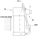
FIG. 1 is a side view illustrating a radiator-intercooler integrated module according to an embodiment of the present disclosure; -
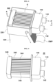
FIG. 2A is a perspective view illustrating a low-temperature radiator of the radiator-intercooler integrated module according to an embodiment of the present disclosure; -
FIG. 2B is a perspective view illustrating a radiator-intercooler integrated module according to another embodiment of the present disclosure; -
FIG. 3 is a view illustrating a state in which a part of the low-temperature radiator of the radiator-intercooler integrated module according to the embodiment of the present disclosure is removed; -
FIG. 4 is a view illustrating an intercooler of the radiator-intercooler integrated module according to the embodiment of the present disclosure; -
FIG. 5A is a sectional view taken along line A-A' ofFIG. 3 and illustrating the case where an exit tank is disposed on an upper side of a radiator core; -
FIG. 5B is a sectional view taken in the same direction as inFIG. 5A and illustrating the case where the exit tank is disposed on a lower side of a radiator; -
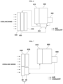
FIG. 6 is a general scheme illustrating a layout of a general front region of a vehicle; and -
FIG. 7 is a view schematically illustrating a layout of a front region of a vehicle in which the radiator-intercooler integrated module according to the embodiment of the present disclosure is mounted. - Hereinafter, exemplary embodiments of the present disclosure will be described in detail with reference to the accompanying drawings. Specific structures or functions described in the embodiments of the present disclosure are merely for illustrative purposes. Embodiments according to the concept of the present disclosure may be implemented in various forms, and it should be understood that they should not be construed as being limited to the embodiments described in the present specification, but include all of modifications included in the scope of the appended claims.
- It will be understood that, although the terms "first," "second," etc. may be used herein to describe various elements, these elements should not be limited by these terms. These terms are only used to distinguish one element from another element. For instance, a first element discussed below could be termed a second element without departing from the teachings of the present invention. Similarly, the second element could also be termed the first element.
- It will be understood that when an element is referred to as being "coupled" or "connected" to another element, it can be directly coupled or connected to the other element or intervening elements may be present therebetween. In contrast, it should be understood that when an element is referred to as being "directly coupled" or "directly connected" to another element, there are no intervening elements present. Other expressions that explain the relationship between elements, such as "between," "directly between," "adjacent to," or "directly adjacent to," should be construed in the same way.
- Like reference numerals denote like components throughout the specification. In the meantime, the terminology used herein is for the purpose of describing particular embodiments only and is not intended to be limiting. As used herein, the singular forms "a," "an," and "the" are intended to include the plural forms as well, unless the context clearly indicates otherwise. It will be further understood that the terms "comprise," "include," "have," etc., when used in this specification, specify the presence of stated components, steps, operations, and/or elements, but do not preclude the presence or addition of one or more other components, steps, operations, and/or elements thereof.
- Hereinafter, the present disclosure will be described in detail with reference to the accompanying drawings. As illustrated in
FIG. 1 , a radiator-intercooler integratedmodule 1 according to the present invention includes a low-temperature radiator 20 and a water cooledintercooler 40. The low-temperature radiator 20 and the water cooledintercooler 40 are integrated as a single assembly. - Referring to
FIGS. 2A and2B , the low-temperature radiator 20 includes aninlet tank 120, anexit tank 220, and aradiator core 320. Theinlet tank 120 and theexit tank 220 are disposed at each side of theradiator core 320. According to an exemplary embodiment of the present disclosure, as illustrated inFIG. 2A , when the radiator-intercooler integrated module according to the present disclosure is mounted in a vehicle, theinlet tank 120 is disposed below theradiator core 320, and theexit tank 220 is disposed above theradiator core 320. According to another exemplary embodiment of the present disclosure, as illustrated inFIG. 2B , when the radiator-intercooler integrated module according to the present disclosure is mounted in a vehicle, theexit tank 220 is disposed below theradiator core 320, and theinlet tank 120 is disposed above theradiator core 320. Hereinafter, the present invention is described based on which theinlet tank 120 is disposed below theradiator core 320. However, as described above, the positions of theinlet tank 120 and theexit tank 220 may be changed. - The
inlet tank 120 may include awater inlet 122. Thewater inlet 122 may be supplied with a coolant from a coolant supply source or an electric water pump (EWP). Theradiator core 320 may be disposed above theinlet tank 120. On the contrary, as described above, when theexit tank 220 is disposed below theradiator core 320 and theinlet tank 120 is disposed above theradiator core 320, theradiator core 320 may be disposed below theinlet tank 120. Theradiator core 320 may includecoolant pipelines 322 along which a coolant flows. The coolant of theinlet tank 120 which is introduced from thewater inlet 122 flows through theradiator core 320. Heat exchange between cooling wind passing theradiator core 320 and the coolant passing thecoolant pipelines 322 occurs at theradiator core 320. A plurality ofradiator cooling fins 324 may be provided to theradiator core 320 along thecoolant pipelines 322 and promote cooling of the coolant while the cooling wind passes theradiator cooling fins 324. - The
exit tank 220 may be disposed above theradiator core 320. On the contrary, as described above, when theinlet tank 120 is disposed above theradiator core 320, theexit tank 220 may be disposed below theradiator core 320. The coolant cooled while passing theradiator core 320 may be introduced into theexit tank 220. Theexit tank 220 may be equipped with awater outlet 222. The coolant passing theexit tank 220 may be discharged to the outside of the radiator-intercooler integratedmodule 1 through thewater outlet 222. The coolant recirculates around the radiator-intercooler integratedmodule 1 through the electric water pump (EWP). Theexit tank 220 may include anopening 224 that passes through a part of theexit tank 220. A holding space S is provided inside theexit tank 220. - As illustrated in
FIGS. 3 and 4 , the water cooledintercooler 40 is integrated into the low-temperature radiator 20. In particular, the water cooledintercooler 40 is mounted on theexit tank 220 and is received in the holding space S. The water cooledintercooler 40 may include afirst tank 140, asecond tank 240, and acooling core 340. Thefirst tank 140 and thesecond tank 240 may be disposed at each side of thecooling core 340. Thefirst tank 140 may have anair inlet 142 and anair outlet 144. Compressed air of a turbocharger may be introduced into theair inlet 142. The air flowing into theoutlet tank 220 through theair inlet 142 may be discharged through theair outlet 144. According to an exemplary embodiment of the present disclosure, thefirst tank 140 may protrude from theexit tank 220 and, more particularly, may protrude from theopening 224. - Air introduced into the
first tank 140 passes thecooling core 340. As indicated by an arrow and a dotted line ofFIG. 3 , the compressed air supplied through the turbocharger is introduced into thefirst tank 140 through theair inlet 142, cooled through thecooling core 340, and then discharged through theair outlet 144 of thefirst tank 140. Thecooling core 340 may includeair pipelines 342 through which the compressed air introduced into thefirst tank 140 may flow. As illustrated inFIG. 5A , the compressed air passing theair pipelines 342 is configured to exchange heat with the coolant passing theradiator core 320 and then flow in theoutlet tank 220 from theradiator core 320, thereby reducing a temperature thereof. Arrows ofFIG. 5A indicate a flow direction of the coolant. - In other words, the coolant inside the low-
temperature radiator 20 may be cooled by the cooling wind. The coolant cooled in this way cools the compressed air introduced into thecooling core 340 in theexit tank 220 while passing the water cooledintercooler 40. Meanwhile,FIG. 5A illustrates a case where theexit tank 220 is disposed above theradiator core 320 and the coolant moves up from bottom to top. On the contrary,FIG. 5B illustrates a flow direction of the coolant that moves down from top to bottom when theexit tank 220 is disposed below theradiator core 320. - According to an exemplary embodiment of the present disclosure, a plurality of
intercooler cooling fins 344 are provided along theair pipelines 342. Theintercooler cooling fins 344 enables a coolant to more effectively cool air inside theair pipelines 342 while the coolant passes by theair pipelines 342. The compressed air passing theair pipelines 342 may pass thesecond tank 240, pass theair pipelines 342 again, and return to thefirst tank 140. The cooled compressed air returning to thefirst tank 140 exits through theair outlet 144 and is supplied to anintake manifold 610. -
FIG. 6 illustrates an exemplary front region of a vehicle in which a water cooled intercooler is mounted, andFIG. 7 illustrates a front region of a vehicle in which the radiator-intercooler integrated module according to the present disclosure is mounted. As illustrated inFIG. 6 , a heat exchanger including a radiator and a condenser is generally disposed in front of anengine 600 and anintake manifold 610 of a vehicle. In the vehicle to which the water cooled intercooler is applied, a low-temperature radiator 620 is typically disposed in front of a high-temperature radiator 630 disposed in the front region of a vehicle, and is disposed between acondenser 640 and the high-temperature radiator 630. The high-temperature radiator 630 is configured to cool an engine coolant, and the low-temperature radiator 620 is configured to cool a coolant of a water cooledintercooler 650. - Charged air passing a
turbocharger 660 may be cooled while passing the water cooledintercooler 650 and is delivered to theintake manifold 610. The cooling of the charged air may be performed at the low-temperature radiator 620 and by the coolant circulating through the water cooledintercooler 650. In contrast, in the present disclosure illustrated inFIG. 7 , the low-temperature radiator 20 is juxtaposed with thecondenser 640. Accordingly, the low-temperature radiator 20 may be cooled without a loss of cooling wind, and thus a size of the low-temperature radiator 20 may be reduced. - Further, since the water cooled
intercooler 40 is integrated into the low-temperature radiator 20, a structure of the radiator-intercooler integrated module may be simplified, and thus an effect of reducing an overall cost may be achieved. According to the present disclosure, the low-temperature radiator 20 and the water cooledintercooler 40 are mounted at a position where the air cooled intercooler is disposed in the related art. Accordingly, there is no need to change the layout or the engine structure of the vehicle, thereby reducing investment expenses. - To satisfy the increasingly stricter emission control limits, there is a need to expand a usable range of low-pressure exhaust gas recirculation (LPEGR). The air cooled intercooler has a limitation due to a low-temperature freezing problem, whereas the water cooled intercooler may enable expansion of the usable range of the LPEGR in that cooling efficiency can be controlled using the electric water pump and without the freezing problem. According to the present disclosure, the radiator-intercooler integrated module may be mounted at the same position as the conventional air cooled intercooler is mounted, while applying the water cooled intercooler, thereby solving a problem with mounting of the water cooled intercooler.
Claims (7)
- A radiator-intercooler integrated module, comprising:a low-temperature radiator (20);wherein the low-temperature radiator (20) includes:an inlet tank (120) into which a water-based coolant flows;a radiator core (320) disposing the coolant in heat exchange relationship with air, wherein the coolant from the inlet tank (120) flows into the radiator core (320); andan exit tank (220), wherein the coolant passing through the radiator core (320) flows into the exit tank (220),wherein the inlet tank (120) and the exit tank (220) are disposed at opposite ends with respect to the radiator core (320), respectively,characterised in that the radiator-intercooler integrated module comprises a water-cooled intercooler (40) formed integrally with the low-temperature radiator (20) into a single body.
- The radiator-intercooler integrated module of claim 1, wherein the water cooled intercooler (40) is inserted and disposed in the exit tank (220).
- The radiator-intercooler integrated module of claim 2, wherein the exit tank (220) includes:an opening (224) formed by opening a part of the exit tank (220); anda holding space (S) forming an empty space inside the opening (224).
- The radiator-intercooler integrated module of claim 3, wherein the water cooled intercooler (40) is seated in the holding space (S), and a portion of the water cooled intercooler (40) protrudes through the opening (224).
- The radiator-intercooler integrated module of one of claims 2-4, wherein a plurality of radiator cooling fins (324) are formed along the radiator core (320).
- A vehicle comprising:a turbocharger (660) configured to charge air;a radiator-intercooler integrated module (1) according to any of claims 1-5 having a water cooled intercooler (40) configured to receive the charged air from the turbocharger (660) and a low-temperature radiator (20) formed integrally with the water cooled intercooler (40), wherein a coolant that exchanges heat with air circulates the low-temperature radiator (20); andan intake manifold (610) configured to receive the heat-exchanged air discharged from the radiator-intercooler integrated module (1).
- The vehicle of claim 6, wherein the radiator-intercooler integrated module (1) is juxtaposed with a condenser (640) disposed in the front of the vehicle in a width direction of the vehicle.
Applications Claiming Priority (1)
| Application Number | Priority Date | Filing Date | Title |
|---|---|---|---|
| KR1020210006722A KR20220104441A (en) | 2021-01-18 | 2021-01-18 | Integrated module for radiator and intercooler and vehicle including the same |
Publications (2)
| Publication Number | Publication Date |
|---|---|
| EP4030042A1 EP4030042A1 (en) | 2022-07-20 |
| EP4030042B1 true EP4030042B1 (en) | 2025-05-21 |
Family
ID=77518918
Family Applications (1)
| Application Number | Title | Priority Date | Filing Date |
|---|---|---|---|
| EP21191035.1A Active EP4030042B1 (en) | 2021-01-18 | 2021-08-12 | Radiator-intercooler integrated module and vehicle including the same |
Country Status (3)
| Country | Link |
|---|---|
| US (1) | US20220228522A1 (en) |
| EP (1) | EP4030042B1 (en) |
| KR (1) | KR20220104441A (en) |
Families Citing this family (1)
| Publication number | Priority date | Publication date | Assignee | Title |
|---|---|---|---|---|
| FR3156384A1 (en) * | 2023-12-07 | 2025-06-13 | Valeo Systemes Thermiques | Cooling module for automotive vehicle |
Family Cites Families (29)
| Publication number | Priority date | Publication date | Assignee | Title |
|---|---|---|---|---|
| US2843367A (en) * | 1955-05-24 | 1958-07-15 | Young Radiator Co | Heat exchanger |
| US4227570A (en) * | 1979-10-01 | 1980-10-14 | Caterpillar Tractor Co. | Heat exchange structure |
| FR2665523B1 (en) * | 1990-07-31 | 1992-10-16 | Valeo Thermique Moteur Sa | WATER BOX OF A MAIN HEAT EXCHANGER, PARTICULARLY FOR MOTOR VEHICLES, CONTAINING A SECONDARY HEAT EXCHANGER. |
| FR2665524B1 (en) * | 1990-07-31 | 1992-10-16 | Valeo Thermique Moteur Sa | WATER BOX OF A MAIN HEAT EXCHANGER, ESPECIALLY FOR MOTOR VEHICLES, CONTAINING A SECONDARY HEAT EXCHANGER. |
| ES2049154B1 (en) * | 1991-12-03 | 1995-02-16 | Pascual Juann Targa | MIXED HEAT CHANGER FOR AIR INLET CIRCUITS IN INTERNAL COMBUSTION ENGINES. |
| US5316079A (en) * | 1993-02-12 | 1994-05-31 | Paccar Inc | Integrated heat exchanger |
| DE4433165C1 (en) * | 1994-09-16 | 1995-12-21 | Mtu Friedrichshafen Gmbh | Plate=type heat exchanger |
| US5566748A (en) * | 1995-11-13 | 1996-10-22 | Alliedsignal Inc. | Charge air cooler/condenser sub-assembly for use in a motor vehicle |
| KR100387424B1 (en) * | 1996-11-26 | 2003-10-30 | 기아자동차주식회사 | Intercooler for air cooling and water cooling |
| US6634418B2 (en) * | 2000-06-13 | 2003-10-21 | International Truck Intellectual Property Company, Llc | T—style radiator—charge air cooler packaging for a mobile vehicle |
| US6817404B2 (en) * | 2001-10-25 | 2004-11-16 | Deere & Company | Cooling package for agricultural combine |
| US6951240B2 (en) * | 2002-11-06 | 2005-10-04 | Transpro, Inc. | Heat exchanger package |
| FR2856747B1 (en) * | 2003-06-25 | 2005-09-23 | Valeo Thermique Moteur Sa | MODULE FOR COOLING EXHAUST AIR AND RECIRCULATED EXHAUST GASES OF AN INTERNAL COMBUSTION ENGINE OF A MOTOR VEHICLE. |
| US7178579B2 (en) * | 2003-11-26 | 2007-02-20 | Proliance International Inc. | Heat exchanger package with split charge air cooler |
| US7228885B2 (en) * | 2003-11-26 | 2007-06-12 | Proliance International, Inc. | Heat exchanger package with split radiator and split charge air cooler |
| US20050241308A1 (en) * | 2004-04-30 | 2005-11-03 | Iqbal Muhammad H | Integral radiator and charge air cooler |
| CN101189417A (en) * | 2005-06-03 | 2008-05-28 | 贝洱两合公司 | charge air intercooler |
| JP2007278613A (en) * | 2006-04-07 | 2007-10-25 | Calsonic Kansei Corp | Radiator with built-in oil cooler |
| JP4970022B2 (en) * | 2006-08-02 | 2012-07-04 | カルソニックカンセイ株式会社 | Combined heat exchanger and combined heat exchanger system |
| PL2014892T3 (en) * | 2007-07-11 | 2011-02-28 | Joao De Deus & Filhos S A | A heat exchanger arrangement |
| KR101207839B1 (en) * | 2010-09-06 | 2012-12-05 | 한라공조주식회사 | Integrated heat exchanger having sub-radiator and watercool charge air cooler |
| FR2975768B1 (en) * | 2011-05-26 | 2016-01-29 | Valeo Systemes Thermiques | THERMAL EXCHANGER, IN PARTICULAR FOR MOTOR VEHICLE, AND CORRESPONDING AIR INTAKE DEVICE |
| FR2975765B1 (en) * | 2011-05-26 | 2016-01-29 | Valeo Systemes Thermiques | THERMAL EXCHANGER, IN PARTICULAR FOR MOTOR VEHICLE, AND CORRESPONDING AIR INTAKE DEVICE |
| KR101294424B1 (en) | 2011-08-12 | 2013-08-07 | 현대자동차주식회사 | Water Cooling type Turbo Charger System and Operation Method thereof |
| KR101542978B1 (en) * | 2013-12-12 | 2015-08-07 | 현대자동차 주식회사 | Cooling module for vehicle |
| KR101795148B1 (en) * | 2015-09-21 | 2017-11-07 | 현대자동차주식회사 | Hybrid intercooler system using multiple cooling medium and control method thereof |
| SE542203C2 (en) * | 2016-01-15 | 2020-03-10 | Scania Cv Ab | A vehicle with a fan arrangement |
| KR101734769B1 (en) * | 2016-05-17 | 2017-05-11 | 현대자동차주식회사 | Hybrid intercooler system for controlling oil temperature and method for controlling the same |
| WO2020097333A1 (en) * | 2018-11-07 | 2020-05-14 | Enterex America, Llc | Heat exchanger assembly with single helix liquid-cooled charge air cooler |
-
2021
- 2021-01-18 KR KR1020210006722A patent/KR20220104441A/en active Pending
- 2021-08-12 EP EP21191035.1A patent/EP4030042B1/en active Active
- 2021-08-18 US US17/405,567 patent/US20220228522A1/en not_active Abandoned
Also Published As
| Publication number | Publication date |
|---|---|
| KR20220104441A (en) | 2022-07-26 |
| US20220228522A1 (en) | 2022-07-21 |
| EP4030042A1 (en) | 2022-07-20 |
Similar Documents
| Publication | Publication Date | Title |
|---|---|---|
| KR101405234B1 (en) | Radiator for vehicle | |
| US20200384827A1 (en) | Thermal management system for vehicle | |
| US20090078220A1 (en) | Cooling System with Isolated Cooling Circuits | |
| US9618282B2 (en) | Radiator for vehicle | |
| JP2010249129A (en) | Charge air cooler and cooling system | |
| EP2073994A1 (en) | Cooling arrangement at a vehicle | |
| KR20170037806A (en) | Water-cooled charge air cooler with integrated multi-stage cooling | |
| JP4323307B2 (en) | Vehicle heat exchanger system | |
| US20230100546A1 (en) | Cooling system for an electric vehicle | |
| EP2781729A1 (en) | Exhaust gas recirculation system | |
| EP4030042B1 (en) | Radiator-intercooler integrated module and vehicle including the same | |
| JP6641865B2 (en) | Vehicle cooling system | |
| KR20120058952A (en) | Front end module for a motor vehicle | |
| EP4026718A1 (en) | Heat exchange device for vehicles | |
| EP1846651B1 (en) | Arrangement for recirculation of exhaust gases of an internal combustion engine in a vehicle | |
| US8973538B2 (en) | Inline engine having side-mounted heat exchangers | |
| CN111196181B (en) | Cooling system for vehicle | |
| US12187114B2 (en) | Shutter device for vehicle | |
| EP4015976B1 (en) | Heat exchanger | |
| EP4095366B1 (en) | Cooling system for vehicle | |
| KR20230136254A (en) | Cooling module | |
| CN223340435U (en) | Vehicle thermal management system and vehicle | |
| JP6354198B2 (en) | Radiator | |
| KR20140076218A (en) | Cooling system using engine cover for vehicle | |
| CN114934840B (en) | Intercooler core and intercooler assembly |
Legal Events
| Date | Code | Title | Description |
|---|---|---|---|
| PUAI | Public reference made under article 153(3) epc to a published international application that has entered the european phase |
Free format text: ORIGINAL CODE: 0009012 |
|
| STAA | Information on the status of an ep patent application or granted ep patent |
Free format text: STATUS: THE APPLICATION HAS BEEN PUBLISHED |
|
| AK | Designated contracting states |
Kind code of ref document: A1 Designated state(s): AL AT BE BG CH CY CZ DE DK EE ES FI FR GB GR HR HU IE IS IT LI LT LU LV MC MK MT NL NO PL PT RO RS SE SI SK SM TR |
|
| STAA | Information on the status of an ep patent application or granted ep patent |
Free format text: STATUS: REQUEST FOR EXAMINATION WAS MADE |
|
| 17P | Request for examination filed |
Effective date: 20230111 |
|
| RBV | Designated contracting states (corrected) |
Designated state(s): AL AT BE BG CH CY CZ DE DK EE ES FI FR GB GR HR HU IE IS IT LI LT LU LV MC MK MT NL NO PL PT RO RS SE SI SK SM TR |
|
| P01 | Opt-out of the competence of the unified patent court (upc) registered |
Effective date: 20230522 |
|
| GRAP | Despatch of communication of intention to grant a patent |
Free format text: ORIGINAL CODE: EPIDOSNIGR1 |
|
| STAA | Information on the status of an ep patent application or granted ep patent |
Free format text: STATUS: GRANT OF PATENT IS INTENDED |
|
| RIC1 | Information provided on ipc code assigned before grant |
Ipc: F28D 21/00 20060101ALI20241118BHEP Ipc: F01P 3/12 20060101ALI20241118BHEP Ipc: F01P 3/18 20060101ALI20241118BHEP Ipc: F28D 7/00 20060101ALI20241118BHEP Ipc: F28D 1/04 20060101ALI20241118BHEP Ipc: F02B 29/04 20060101AFI20241118BHEP |
|
| INTG | Intention to grant announced |
Effective date: 20241211 |
|
| GRAS | Grant fee paid |
Free format text: ORIGINAL CODE: EPIDOSNIGR3 |
|
| GRAA | (expected) grant |
Free format text: ORIGINAL CODE: 0009210 |
|
| STAA | Information on the status of an ep patent application or granted ep patent |
Free format text: STATUS: THE PATENT HAS BEEN GRANTED |
|
| AK | Designated contracting states |
Kind code of ref document: B1 Designated state(s): AL AT BE BG CH CY CZ DE DK EE ES FI FR GB GR HR HU IE IS IT LI LT LU LV MC MK MT NL NO PL PT RO RS SE SI SK SM TR |
|
| REG | Reference to a national code |
Ref country code: GB Ref legal event code: FG4D |
|
| REG | Reference to a national code |
Ref country code: CH Ref legal event code: EP |
|
| REG | Reference to a national code |
Ref country code: DE Ref legal event code: R096 Ref document number: 602021031037 Country of ref document: DE |
|
| REG | Reference to a national code |
Ref country code: IE Ref legal event code: FG4D |
|
| REG | Reference to a national code |
Ref country code: NL Ref legal event code: MP Effective date: 20250521 |
|
| PG25 | Lapsed in a contracting state [announced via postgrant information from national office to epo] |
Ref country code: FI Free format text: LAPSE BECAUSE OF FAILURE TO SUBMIT A TRANSLATION OF THE DESCRIPTION OR TO PAY THE FEE WITHIN THE PRESCRIBED TIME-LIMIT Effective date: 20250521 Ref country code: ES Free format text: LAPSE BECAUSE OF FAILURE TO SUBMIT A TRANSLATION OF THE DESCRIPTION OR TO PAY THE FEE WITHIN THE PRESCRIBED TIME-LIMIT Effective date: 20250521 Ref country code: PT Free format text: LAPSE BECAUSE OF FAILURE TO SUBMIT A TRANSLATION OF THE DESCRIPTION OR TO PAY THE FEE WITHIN THE PRESCRIBED TIME-LIMIT Effective date: 20250922 |
|
| PGFP | Annual fee paid to national office [announced via postgrant information from national office to epo] |
Ref country code: DE Payment date: 20250724 Year of fee payment: 5 |
|
| REG | Reference to a national code |
Ref country code: LT Ref legal event code: MG9D |
|
| PG25 | Lapsed in a contracting state [announced via postgrant information from national office to epo] |
Ref country code: NO Free format text: LAPSE BECAUSE OF FAILURE TO SUBMIT A TRANSLATION OF THE DESCRIPTION OR TO PAY THE FEE WITHIN THE PRESCRIBED TIME-LIMIT Effective date: 20250821 Ref country code: GR Free format text: LAPSE BECAUSE OF FAILURE TO SUBMIT A TRANSLATION OF THE DESCRIPTION OR TO PAY THE FEE WITHIN THE PRESCRIBED TIME-LIMIT Effective date: 20250822 |
|
| PG25 | Lapsed in a contracting state [announced via postgrant information from national office to epo] |
Ref country code: NL Free format text: LAPSE BECAUSE OF FAILURE TO SUBMIT A TRANSLATION OF THE DESCRIPTION OR TO PAY THE FEE WITHIN THE PRESCRIBED TIME-LIMIT Effective date: 20250521 Ref country code: PL Free format text: LAPSE BECAUSE OF FAILURE TO SUBMIT A TRANSLATION OF THE DESCRIPTION OR TO PAY THE FEE WITHIN THE PRESCRIBED TIME-LIMIT Effective date: 20250521 |
|
| PG25 | Lapsed in a contracting state [announced via postgrant information from national office to epo] |
Ref country code: BG Free format text: LAPSE BECAUSE OF FAILURE TO SUBMIT A TRANSLATION OF THE DESCRIPTION OR TO PAY THE FEE WITHIN THE PRESCRIBED TIME-LIMIT Effective date: 20250521 |
|
| PGFP | Annual fee paid to national office [announced via postgrant information from national office to epo] |
Ref country code: GB Payment date: 20250822 Year of fee payment: 5 |
|
| PG25 | Lapsed in a contracting state [announced via postgrant information from national office to epo] |
Ref country code: HR Free format text: LAPSE BECAUSE OF FAILURE TO SUBMIT A TRANSLATION OF THE DESCRIPTION OR TO PAY THE FEE WITHIN THE PRESCRIBED TIME-LIMIT Effective date: 20250521 |
|
| PGFP | Annual fee paid to national office [announced via postgrant information from national office to epo] |
Ref country code: FR Payment date: 20250821 Year of fee payment: 5 Ref country code: AT Payment date: 20251020 Year of fee payment: 5 |
|
| PG25 | Lapsed in a contracting state [announced via postgrant information from national office to epo] |
Ref country code: RS Free format text: LAPSE BECAUSE OF FAILURE TO SUBMIT A TRANSLATION OF THE DESCRIPTION OR TO PAY THE FEE WITHIN THE PRESCRIBED TIME-LIMIT Effective date: 20250821 |
|
| PG25 | Lapsed in a contracting state [announced via postgrant information from national office to epo] |
Ref country code: IS Free format text: LAPSE BECAUSE OF FAILURE TO SUBMIT A TRANSLATION OF THE DESCRIPTION OR TO PAY THE FEE WITHIN THE PRESCRIBED TIME-LIMIT Effective date: 20250921 |
|
| PG25 | Lapsed in a contracting state [announced via postgrant information from national office to epo] |
Ref country code: LV Free format text: LAPSE BECAUSE OF FAILURE TO SUBMIT A TRANSLATION OF THE DESCRIPTION OR TO PAY THE FEE WITHIN THE PRESCRIBED TIME-LIMIT Effective date: 20250521 |
|
| REG | Reference to a national code |
Ref country code: AT Ref legal event code: MK05 Ref document number: 1796924 Country of ref document: AT Kind code of ref document: T Effective date: 20250521 |
|
| PG25 | Lapsed in a contracting state [announced via postgrant information from national office to epo] |
Ref country code: DK Free format text: LAPSE BECAUSE OF FAILURE TO SUBMIT A TRANSLATION OF THE DESCRIPTION OR TO PAY THE FEE WITHIN THE PRESCRIBED TIME-LIMIT Effective date: 20250521 Ref country code: AT Free format text: LAPSE BECAUSE OF FAILURE TO SUBMIT A TRANSLATION OF THE DESCRIPTION OR TO PAY THE FEE WITHIN THE PRESCRIBED TIME-LIMIT Effective date: 20250521 Ref country code: SM Free format text: LAPSE BECAUSE OF FAILURE TO SUBMIT A TRANSLATION OF THE DESCRIPTION OR TO PAY THE FEE WITHIN THE PRESCRIBED TIME-LIMIT Effective date: 20250521 |
|
| PG25 | Lapsed in a contracting state [announced via postgrant information from national office to epo] |
Ref country code: CZ Free format text: LAPSE BECAUSE OF FAILURE TO SUBMIT A TRANSLATION OF THE DESCRIPTION OR TO PAY THE FEE WITHIN THE PRESCRIBED TIME-LIMIT Effective date: 20250521 |
|
| PG25 | Lapsed in a contracting state [announced via postgrant information from national office to epo] |
Ref country code: EE Free format text: LAPSE BECAUSE OF FAILURE TO SUBMIT A TRANSLATION OF THE DESCRIPTION OR TO PAY THE FEE WITHIN THE PRESCRIBED TIME-LIMIT Effective date: 20250521 |
|
| PG25 | Lapsed in a contracting state [announced via postgrant information from national office to epo] |
Ref country code: RO Free format text: LAPSE BECAUSE OF FAILURE TO SUBMIT A TRANSLATION OF THE DESCRIPTION OR TO PAY THE FEE WITHIN THE PRESCRIBED TIME-LIMIT Effective date: 20250521 Ref country code: SK Free format text: LAPSE BECAUSE OF FAILURE TO SUBMIT A TRANSLATION OF THE DESCRIPTION OR TO PAY THE FEE WITHIN THE PRESCRIBED TIME-LIMIT Effective date: 20250521 |
|
| PG25 | Lapsed in a contracting state [announced via postgrant information from national office to epo] |
Ref country code: IT Free format text: LAPSE BECAUSE OF FAILURE TO SUBMIT A TRANSLATION OF THE DESCRIPTION OR TO PAY THE FEE WITHIN THE PRESCRIBED TIME-LIMIT Effective date: 20250521 |
|
| REG | Reference to a national code |
Ref country code: DE Ref legal event code: R097 Ref document number: 602021031037 Country of ref document: DE |
|
| REG | Reference to a national code |
Ref country code: CH Ref legal event code: H13 Free format text: ST27 STATUS EVENT CODE: U-0-0-H10-H13 (AS PROVIDED BY THE NATIONAL OFFICE) Effective date: 20260324 |
|
| PLBE | No opposition filed within time limit |
Free format text: ORIGINAL CODE: 0009261 |
|
| STAA | Information on the status of an ep patent application or granted ep patent |
Free format text: STATUS: NO OPPOSITION FILED WITHIN TIME LIMIT |
|
| PG25 | Lapsed in a contracting state [announced via postgrant information from national office to epo] |
Ref country code: MC Free format text: LAPSE BECAUSE OF FAILURE TO SUBMIT A TRANSLATION OF THE DESCRIPTION OR TO PAY THE FEE WITHIN THE PRESCRIBED TIME-LIMIT Effective date: 20250521 |
|
| REG | Reference to a national code |
Ref country code: CH Ref legal event code: L10 Free format text: ST27 STATUS EVENT CODE: U-0-0-L10-L00 (AS PROVIDED BY THE NATIONAL OFFICE) Effective date: 20260402 |
|
| PG25 | Lapsed in a contracting state [announced via postgrant information from national office to epo] |
Ref country code: LU Free format text: LAPSE BECAUSE OF NON-PAYMENT OF DUE FEES Effective date: 20250812 |
|
| PG25 | Lapsed in a contracting state [announced via postgrant information from national office to epo] |
Ref country code: CH Free format text: LAPSE BECAUSE OF NON-PAYMENT OF DUE FEES Effective date: 20250831 |
|
| 26N | No opposition filed |
Effective date: 20260224 |