EP4029980B1 - A laundry dryer provided with a steam generator and a corresponding method - Google Patents
A laundry dryer provided with a steam generator and a corresponding method Download PDFInfo
- Publication number
- EP4029980B1 EP4029980B1 EP21151487.2A EP21151487A EP4029980B1 EP 4029980 B1 EP4029980 B1 EP 4029980B1 EP 21151487 A EP21151487 A EP 21151487A EP 4029980 B1 EP4029980 B1 EP 4029980B1
- Authority
- EP
- European Patent Office
- Prior art keywords
- liquid
- laundry
- loading unit
- lid
- receiving element
- Prior art date
- Legal status (The legal status is an assumption and is not a legal conclusion. Google has not performed a legal analysis and makes no representation as to the accuracy of the status listed.)
- Active
Links
Images


Classifications
-
- D—TEXTILES; PAPER
- D06—TREATMENT OF TEXTILES OR THE LIKE; LAUNDERING; FLEXIBLE MATERIALS NOT OTHERWISE PROVIDED FOR
- D06F—LAUNDERING, DRYING, IRONING, PRESSING OR FOLDING TEXTILE ARTICLES
- D06F58/00—Domestic laundry dryers
- D06F58/20—General details of domestic laundry dryers
- D06F58/203—Laundry conditioning arrangements
-
- D—TEXTILES; PAPER
- D06—TREATMENT OF TEXTILES OR THE LIKE; LAUNDERING; FLEXIBLE MATERIALS NOT OTHERWISE PROVIDED FOR
- D06F—LAUNDERING, DRYING, IRONING, PRESSING OR FOLDING TEXTILE ARTICLES
- D06F58/00—Domestic laundry dryers
- D06F58/02—Domestic laundry dryers having dryer drums rotating about a horizontal axis
-
- D—TEXTILES; PAPER
- D06—TREATMENT OF TEXTILES OR THE LIKE; LAUNDERING; FLEXIBLE MATERIALS NOT OTHERWISE PROVIDED FOR
- D06F—LAUNDERING, DRYING, IRONING, PRESSING OR FOLDING TEXTILE ARTICLES
- D06F58/00—Domestic laundry dryers
- D06F58/20—General details of domestic laundry dryers
-
- D—TEXTILES; PAPER
- D06—TREATMENT OF TEXTILES OR THE LIKE; LAUNDERING; FLEXIBLE MATERIALS NOT OTHERWISE PROVIDED FOR
- D06F—LAUNDERING, DRYING, IRONING, PRESSING OR FOLDING TEXTILE ARTICLES
- D06F58/00—Domestic laundry dryers
- D06F58/20—General details of domestic laundry dryers
- D06F58/22—Lint collecting arrangements
-
- D—TEXTILES; PAPER
- D06—TREATMENT OF TEXTILES OR THE LIKE; LAUNDERING; FLEXIBLE MATERIALS NOT OTHERWISE PROVIDED FOR
- D06F—LAUNDERING, DRYING, IRONING, PRESSING OR FOLDING TEXTILE ARTICLES
- D06F58/00—Domestic laundry dryers
- D06F58/20—General details of domestic laundry dryers
- D06F58/24—Condensing arrangements
Definitions
- the present invention refers to a laundry drier provided with a steam generator and a corresponding method.
- laundry driers for example tumble driers, or washer-driers (i.e. laundry appliances that can both wash and dry the laundry), typically comprise a casing, or housing, containing a laundry treating compartment wherein laundry to be treated can be loaded.
- the laundry treating compartment is typically a rotatable drum, housed inside the casing, and rotatable with respect to a rotation axis that can be, with respect to a horizontal surface on which the laundry drier is configured to lay, substantially horizontal or slightly inclined (in the so called “horizontal axis” laundry driers), or substantially vertical (in the so called “horizontal axis” laundry driers).
- the drum In known tumble driers, the drum is generally rotatably supported in the casing by rollers, pivoted to a supporting structure static with respect to the casing.
- the casing also houses a washing tub, typically suspended to the casing by springs and dampers, in which the drum is rotatably contained.
- the laundry treating compartment is static with respect to the casing; in this case, the laundry drier, typically called “drying cabinet”, is a sort of heated cabinet wherein the laundry can be hung in order to be dried.
- Known laundry driers also comprise a drying system comprising an air conduit, passing through and comprising the laundry treating compartment, an air moving device (typically a fan or blower), generating, when operated, an air flow which passes through the air conduit, an air heating device (e.g. an electric heater, a heat pump system, a gas burner), positioned at least partially within the air conduit so as to heat the air flow before it passes through the laundry treating compartment.
- an air moving device typically a fan or blower
- an air heating device e.g. an electric heater, a heat pump system, a gas burner
- the air conduit is arranged in such a way that the air flow, after passing through the laundry treating compartment, is discharged to the external environment, optionally after being at least partially deprived of moisture in a moisture condensing device (e.g. an air-air heat exchanger).
- a moisture condensing device e.g. an air-air heat exchanger
- the air conduit is arranged in such a way to circulate the airflow through the laundry treating compartment; in this case, moisture laden air exiting the laundry treating compartment is deprived of moisture in a moisture condensing device, and then heated again by the air heating device before being pumped again into the laundry treating compartment.
- Some known laundry driers also comprise a steam generator, allowing to produce steam and release it within the inner volume of the laundry treating compartment, so as to contact the laundry contained therein and exert on the latter one or more advantageous actions (for example a disinfecting actions and/or an anti-crease actions, etc.).
- steam means the gas or vapour into which water, or a liquid containing water mixed with one or more additives (e.g. a fragrance), is changed when boiled.
- the steam generator typically comprises a main liquid reservoir, wherein a liquid (i.e. water or water mixed with one or more additives) can be loaded, and a liquid heating system, operable for generating heat to heat the liquid, so as to produce steam which is delivered to the laundry treating compartment via a steam delivery conduit fluidly connecting the steam generator to the laundry treating compartment.
- a liquid i.e. water or water mixed with one or more additives
- a liquid heating system operable for generating heat to heat the liquid, so as to produce steam which is delivered to the laundry treating compartment via a steam delivery conduit fluidly connecting the steam generator to the laundry treating compartment.
- the main liquid reservoir is a boiler, housed within the casing externally to the laundry treating compartment, in which a liquid can be loaded and heated, and the liquid heating device is an electric heater arranged in the boiler for heating such a liquid and producing steam, which is driven towards and released into the inner volume of the laundry treating compartment via the steam delivery conduit.
- the liquid heating device is external to the main liquid reservoir, and it is arranged in such a way to heat the liquid after it exits the main liquid reservoir;
- the liquid heating device can be an electric heater placed within a pipe fluidly connecting the main liquid reservoir to the laundry treating compartment, so as to heat a liquid exiting the main liquid reservoir and passing through such a pipe, and to convert it into steam, that is released into the laundry treating compartment.
- the liquid to be converted into steam is loaded into the main liquid reservoir via a liquid loading unit which comprises a liquid receiving element, having an outlet opening fluidly connected to the main liquid reservoir, and a filter, provided upstream to or at the outlet opening, so as to filter a liquid flowing out of the liquid receiving element via the outlet opening.
- a liquid loading unit which comprises a liquid receiving element, having an outlet opening fluidly connected to the main liquid reservoir, and a filter, provided upstream to or at the outlet opening, so as to filter a liquid flowing out of the liquid receiving element via the outlet opening.
- a known solution of this kind is shown in the international patent application n. WO2014/075848 , disclosing a laundry washing and/or drying machine comprising a body, a steam generator situated in the body and generating steam to be delivered into the washing tub, a receptacle situated inside or in vicinity of the steam generator and wherein liquid is accumulated to be used in the steam generator, an opening arranged on the body and wherein the condensation tank, the detergent dispenser, etc. are placed, a funnel situated in the body, accessed by means of the opening and into which the liquid is delivered, and a hose providing the liquid in the funnel to be transferred to the receptacle.
- a cover is placed onto the funnel, having an open position and a closed position.
- This known solution comprises a filter casing, detachably mounted into the funnel, and a filter situated at the base of the filter casing for filtering the liquid delivered to the hose by passing through the filter casing.
- the filter, the cover and the filter casing can move together in an integrated manner.
- the filter casing placed into the funnel can be dislodged from the funnel by the user and cleaned when desired.
- the cover after loading the liquid, is not properly closed, there is the risk that the component (i.e. the condensation tank or the detergent dispenser of the laundry washing and/or drying machine) to be placed in the opening via which the funnel can be accessed, can bump into the cover while being inserted into the opening, with the risk of damaging the cover and/or the component.
- the component i.e. the condensation tank or the detergent dispenser of the laundry washing and/or drying machine
- a laundry machine includes a selectively rotatable drum and a steam generator for generating steam and supplying the steam to the drum.
- a detachable water supply source detached from the steam generator, is provided for being filled with water that is supplied to the steam generator by means of a water supply hose and a pump.
- the water supply source can be mounted in a drawer slidably received in a drawer housing.
- EP3224401A1 discloses a laundry dryer comprising a body, a drum in which laundry to be dried is placed, an air circulation duct providing the delivery of the drying air onto the laundry in the drum, a heat exchanger that is disposed on the air circulation duct and that enables the temperature of the drying air to be changed; at least one additional filter that retains particles in the drying air and a tank in which the condensed water is stored, that has a port.
- a cover, that has an inlet thereon, is mounted, preferably hinged, to the port of the tank so as to be opened/closed, thereby providing access into the additional filter.
- US2014238086A1 discloses a laundry treating apparatus having a receiving space to receive laundry, a laundry support unit provided in the receiving space to support the laundry, and a machinery compartment provided as a space separated from the receiving space, the machinery compartment being provided with at least one selected from between an air supply unit to supply air to the receiving space and a water supply unit to supply water, in the form of steam or mist to the receiving space.
- the aim of the present invention is therefore to provide a laundry drier provided with a steam generator which simplifies, with respect to cited prior art, the manual loading of a liquid to be converted into steam into such a steam generator.
- a further object of the invention is obtaining a laundry drier provided with a steam generator in which the risk of possible damages caused by the operations for manually loading a liquid to be converted into steam into such a steam generator is low.
- Applicant has found that, by using, for manually loading a liquid into the steam generator, a liquid loading unit provided with a filter and with a lid selectively closable/openable for respectively preventing/allowing to reach such a filter, and provided with one or more liquid loading openings allowing to manually load a liquid in the liquid receiving element even when the lid is closed, the loading procedure is very easy and quick.
- a laundry dryer comprising:
- the filter is removably associated to the liquid receiving element.
- the expression "reaching" the filter has to be construed as accessing the filter in a way suitable for completely cleaning the latter and/or for grasping the filter in such a way to be able to remove it, if removable, for cleaning or replacing it.
- the expression "preventing a user from reaching" the filter has to be construed as avoiding that a user can access the filter in such a way to completely clean the latter or to grasp such a filter in such a way to remove it, if removable, for cleaning or replacing it.
- the expression “reaching the filter” does not encompass slightly touching the filter, nor touching only a small portion of the latter.
- the one or more liquid loading openings comprise a first liquid loading opening provided at the liquid receiving element and fluidly connected to the outlet opening via a fluid path bypassing the lid and passing through the filter.
- the first liquid loading opening is provided in the liquid receiving element.
- the liquid receiving element is box shaped and hollow.
- the liquid receiving element comprises an hopper, in which the outlet opening and the first liquid loading opening are provided, wherein the outlet opening and the first liquid loading opening are fluidly connected to one another.
- the first liquid loading opening and the outlet opening are fluidly connected to one another via a connecting conduit provided at least partially in the hopper.
- the first liquid loading opening and the outlet opening are defined by two portions of a same aperture provided in the liquid receiving element; preferably, in this advantageous embodiment, the first liquid loading opening, the outlet opening, and the filter are reciprocally positioned in such a way that, when the lid is in the closed position, it at least partially overlaps the filter and delimits the first loading opening in such a to prevent a user from reaching the filter via the first loading aperture.
- the filter overlaps the outlet opening so that the filter and the outlet opening are aligned with each other, while the first liquid loading opening is misaligned with respect to the filter and the outlet opening.
- the dimensions of the first liquid loading opening are so small that a user can't insert a finger within such a first liquid loading opening, far enough for reaching the filter.
- a separating element interposed between such a first liquid loading opening and the filter for preventing a user from reaching the filter.
- the liquid loading unit comprises a plurality of liquid loading openings which comprise one or more second liquid loading openings, provided in the lid, via which a liquid can be loaded in the liquid receiving element and go to the outlet opening, passing through the lid, when the latter is in the closed position.
- the laundry dryer comprises a box-shaped seat, accessible from the external and from a front side of the casing, suitable for removably receiving a drawer and comprising, in its bottom region, a housing, fluidly connected to the main liquid reservoir, and in which the liquid loading unit is at least partially housed in a permanent or removable way.
- the laundry dryer comprises a sealing element arranged in the housing or in a portion of the liquid loading unit positioned, or that can be positioned, or that is configured to be positioned, in the housing, so as to be interposed between the housing and the portion for achieving a watertight coupling thereof.
- the laundry dryer comprises a moisture condensing device positioned at least partially within the air conduit, downstream of the laundry treating compartment, so as to condense and remove moisture contained in the air flow, the moisture condensing device being fluidly connected to a condensate container receiving condensate removed from the air flow by the moisture condensing device.
- the laundry dryer comprises a pumping system, fluidly connecting the condensate container to the liquid loading unit, comprising a pump that sucks a liquid from the condensate container and pumps it to the liquid loading unit via a piping system having a condensate outlet provided at the liquid loading unit, and/or to a liquid collecting reservoir of the laundry drier, fluidly connected or connectable to the piping system.
- the laundry dryer which comprises a pumping system, fluidly connecting the condensate container to the liquid loading unit, comprising a pump that sucks a liquid from the condensate container and pumps it to the liquid loading unit via a piping system having a condensate outlet provided at the liquid loading unit, and/or to a liquid collecting reservoir of the laundry drier, fluidly connected or connectable to the piping system, can be made to comprise:
- the condensate outlet is provided at the liquid loading unit upstream of the filter.
- the piping system comprises a first valve operable to selectively direct a liquid, sucked by the pump from the condensate container, to the liquid collecting reservoir and/or to the liquid loading unit.
- a piping branch connector is used to split or drive the main liquid flow provided by the pump in a plurality of flows, each having a predetermined flow rate.
- the liquid loading unit comprises an overflow opening for discharging outside of the liquid loading unit a liquid contained within the liquid loading unit and exceeding a prefixed level, so as to prevent the liquid from flowing back through the one or more liquid loading openings.
- the overflow opening is comprised in the lid and/or in the liquid receiving element, or it is defined by a gap between the lid and the liquid receiving element.
- the overflow opening is fluidly connected to the condensate container in such a way that a liquid flowing out of the overflow opening is drained to the condensate container.
- the overflow opening is fluidly connected to the condensate container through an overflow reservoir receiving a liquid flowing out of the overflow opening, and fluidly connected to the condensate container so as to drain to the latter the liquid received from the overflow opening.
- the overflow reservoir can be advantageously defined by a portion of bottom region of the box-shaped seat.
- the overflow opening is positioned at a prefixed level that prevents the flow back of a liquid from the liquid loading unit to the condensate outlet of the piping system.
- the liquid heating device comprises one or more electric heaters housed within the main liquid reservoir for heating a liquid contained therein, and producing steam which is driven towards and released into the inner volume of the laundry treating compartment via the steam delivery conduit.
- the liquid heating device is external to the main liquid reservoir, and it is arranged in such a way to heat the liquid after it exits the main liquid reservoir.
- the liquid heating device can comprise a heating conduit, fluidly connecting the main liquid reservoir to the steam delivery conduit, and one or more electric heaters contained in such a heating conduit, which heat a liquid flowing out of the main liquid reservoir and received by the heating conduit, converting such a liquid into steam before it reaches the steam delivery conduit via which it is released into the laundry treating compartment.
- the laundry dryer comprises a drain conduit, selectively fluidly connecting the main reservoir to the external of the laundry dryer, so as to allow draining outside the laundry drier a liquid contained in the main reservoir.
- the drain conduit is advantageously fluidly connected to the main liquid reservoir by a second valve selectively directing a liquid coming from the main liquid reservoir to the heating conduit and/or to the drain conduit.
- a piping branch connector is used to split or drive liquid coming from the main liquid reservoir toward the heating conduit and/or to the drain conduit.
- the lid is hinged to the liquid receiving element, so as to be moved from the closed to the opened position, and vice-versa, by a rotation, or the lid is slidably connected to the liquid receiving element, so as to be moved from the closed to the opened position, and vice-versa, by sliding on the liquid receiving element.
- the one or more second liquid loading openings have an elongated shape.
- the lid is, in a plan view, substantially U-shaped, so as to define two parallel arms, connected by a crosspiece, and arranged for housing therebetween the first liquid loading opening when the lid is in the closed position.
- one or more of the second liquid loading openings provided in the lid are arranged on one or both the two parallel arms, and/or on the crosspiece of the lid.
- a further aspect of the invention relates a method for loading a liquid to be converted into steam in a laundry drier according to the invention, which method comprises the steps of first removing said drawer (34) from the box-shaped seat (32) and then loading a liquid to be converted into steam in the liquid loading unit of the laundry drier via one or more of the one or more liquid loading openings of the liquid loading unit, while the lid is in the closed position.
- a laundry drier according to the invention is identified by number 1.
- the laundry drier 1 illustrated in attached figures is a tumble drier of the "horizontal axis type"; it is however clear that the invention can be applied, without any substantial modification, also to tumble driers of the vertical axis" type, to washer-driers, both of the “horizontal axis” and of the “vertical axis” type, and also to "drying cabinets”.
- the laundry drier 1 (being it a tumble drier, a washer-drier, or a drying cabinet) comprises a casing 2, preferably parallelepiped, configured to be positioned on a horizontal surface 3, for example the floor of a building, preferably by suitable feet 4, one or more of which can have, advantageously, an adjustable height, so as to adapt to a possible not perfect planarity of the horizontal surface 3.
- the laundry drier 1 comprises a laundry treating compartment 5, mounted within the casing 2, wherein laundry to be treated, not illustrated, can be loaded, advantageously via an access opening, also not illustrated, obtained in the casing 2, and selectively closable by a loading/unloading door 6, preferably hinged to the casing 2.
- the laundry drier 1 is a tumble drier
- the laundry treating compartment 5 is a drum 50, preferably containing one or more lifter 51, rotatably housed within the casing 2, and preferably rotatably supported by rollers 7, which are advantageously pivoted to a supporting structure 8, static with respect to the casing 2.
- the casing 2 also houses a washing tub, not illustrated, preferably suspended within the casing 2 through springs and dumpers, also not illustrated, in which the drum 50 is rotatably contained.
- the laundry treating compartment 5 is simply a hollow compartment, defined within the cabinet 2, preferably provided with clothes hanger bars or hooks, both not illustrated, for hanging the laundry.
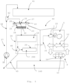
- the laundry drier 1 advantageously comprises a a drying system 9, comprising an air conduit 10, passing through and comprising the laundry treating compartment 5, an air moving device 11, for example a fan or blower 110, generating, when operated, an air flow 12 (schematically illustrated in figures 4 and 5 with arrows) which passes through the air conduit 10, an air heating device 13, positioned at least partially within the air conduit 10 so as to heat the air flow 12 before it passes through the laundry treating compartment 5.
- a drying system 9 comprising an air conduit 10, passing through and comprising the laundry treating compartment 5, an air moving device 11, for example a fan or blower 110, generating, when operated, an air flow 12 (schematically illustrated in figures 4 and 5 with arrows) which passes through the air conduit 10, an air heating device 13, positioned at least partially within the air conduit 10 so as to heat the air flow 12 before it passes through the laundry treating compartment 5.
- the air conduit 10 advantageously comprises such a drum 50 (which is preferably arranged to be crossed from its rear side 50a to its front side 50b by the air flow 12), and a plurality of air ducts 52, one or more of which are preferably at least partially comprised in the supporting structure 8 and/or in the loading/unloading door 6, and which are fluidly connected to the drum 50 in such a way to supply the air flow 12 within the drum 50 and to receive the air flow 12 exiting the latter.
- a drum 50 which is preferably arranged to be crossed from its rear side 50a to its front side 50b by the air flow 12
- a plurality of air ducts 52 one or more of which are preferably at least partially comprised in the supporting structure 8 and/or in the loading/unloading door 6, and which are fluidly connected to the drum 50 in such a way to supply the air flow 12 within the drum 50 and to receive the air flow 12 exiting the latter.
- the air conduit 10 is arranged in such a way to circulate the airflow 12 through the laundry treating compartment 5; in this case, moisture laden air flow 12 exiting the laundry treating compartment 5 is deprived of moisture in a moisture condensing device 14, and then it is heated again by the air heating device 13 before being pumped again into the laundry treating compartment 5.
- the drying system 9 can also advantageously comprise a lint filter 15, arranged in the air conduit 10, downstream of the laundry treating compartment 5, for trapping lint or fluff released from the laundry and carried out of the laundry treating compartment 5 by the air flow 12.
- a lint filter 15 arranged in the air conduit 10, downstream of the laundry treating compartment 5, for trapping lint or fluff released from the laundry and carried out of the laundry treating compartment 5 by the air flow 12.
- the air conduit 10 is arranged in such a way that the air flow 12, after passing through the laundry treating compartment 5, instead of being circulated is discharged to the external environment, optionally after being at least partially deprived of moisture in a moisture condensing device 14.
- the moisture condensing device 14 is a heat exchanger arranged for being lapped by the air flow 12 and for causing an heat exchange between such an air flow 12 and a cold fluid (e.g. cold air or a refrigerant) passing through the heat exchanger, so as to cool down the air flow 12 and to condense the moisture contained therein.
- a cold fluid e.g. cold air or a refrigerant
- the moisture condensing device 14 is fluidly connected to a condensate container 140 receiving condensate removed from the air flow 12 by the moisture condensing device 14;
- the condensate container 140 can be a tray 141 positioned below the moisture condensing device 14, so as to collect condensed-moisture drops falling by gravity from the latter.
- the air heating device 13 is or comprises one or more electric heaters, not illustrated, positioned at least partially within the air conduit 10 so as to heat the air flow 12 passing on it.
- the heating device 13 and the moisture condensing device 14 are part of an heat pump system 16, advantageously comprising a compressor, not illustrated, an expansion valve, also not illustrated, two heat exchangers 17a, 17b (one operating as a condenser, and the other as an evaporator), and conduits, not illustrated, fluidly connecting such elements in a closed circuit; a refrigerant flows through the compressor, the condenser 17a, the expansion valve and the evaporator 17b, and through the conduits connecting these to one another.
- the refrigerant releases heat to the air flow 12 by means of the condenser 17a, which is therefore the heating device 13, and extracts heat and humidity from the air flow 12 by means of the evaporator 17b, which is therefore the moisture condensing device 14.
- the compressor converts electromechanical power to thermal power by compressing the refrigerant in the refrigerant circuit.
- the laundry drier 1 comprises also a steam generator 18 comprising a main liquid reservoir 19, wherein a liquid can be loaded, and a liquid heating device 20 operable for generating heat to heat a liquid contained in and/or coming from the main liquid reservoir 19, so as to produce steam which is delivered to the laundry treating compartment 5 via a steam delivery conduit 21 fluidly connecting the steam generator 18 to the laundry treating compartment 5.
- a steam generator 18 comprising a main liquid reservoir 19, wherein a liquid can be loaded
- a liquid heating device 20 operable for generating heat to heat a liquid contained in and/or coming from the main liquid reservoir 19, so as to produce steam which is delivered to the laundry treating compartment 5 via a steam delivery conduit 21 fluidly connecting the steam generator 18 to the laundry treating compartment 5.
- the liquid heating device 20 comprises one or more electric heaters, housed within the main liquid reservoir 19 for heating a liquid contained therein, and producing steam which is driven towards and released into the inner volume of the laundry treating compartment 5 via the steam delivery conduit 21.
- the liquid heating device 20 is external to the main liquid reservoir 19, and it is arranged in such a way to heat the liquid after it exits the main liquid reservoir 19.
- the liquid heating device 20 can comprise a heating conduit 200, fluidly connecting the main liquid reservoir 19 to the steam delivery conduit 21, and one or more electric heaters, not illustrated, contained in such a heating conduit 200; the one or more electric heaters heat the liquid flowing out of the main liquid reservoir 19 and received by the heating conduit 200, converting such a liquid into steam, before it reaches the steam delivery conduit 21 via which it is released, in the form of steam, into the laundry treating compartment 5.
- the steam delivery conduit 21 releases the steam into the laundry treating compartment 5 via a nozzle 22.
- the laundry drier 1 comprises a liquid loading unit 23, by which a liquid (e.g. water or water mixed with an additive, for example a fragrance) can be manually loaded into the main liquid reservoir 19;
- the liquid loading unit 23 comprises a liquid receiving element 24, having an outlet opening 25, fluidly connected or connectable to the main liquid reservoir 19, and a filter 26, preferably, but not necessarily, removable, provided upstream to or at the outlet opening 25, so as to filter a liquid flowing out of the liquid receiving element 24 via the outlet opening 25.
- the liquid receiving element 24 is box shaped and hollow.
- the liquid loading unit 23 comprises a lid 27, movable with respect to the liquid receiving element 24 between a closed position (as the one illustrated for example in figures 2 , 3 , 4 , 6 , 7 , 8 , 9 , 10 ), in which the lid 27 at least partially overlaps the filter 26, preventing a user from reaching the latter, and an opened position (as the one illustrated for example in figure 10 ) allowing a user to reach the filter 26.
- the expression "reaching" the filter has to be construed as accessing the filter 26 in a way suitable for completely cleaning the latter and/or for grasping the filter in such a way to be able to remove it, if removable, for cleaning or replacing it.
- the expression "preventing a user from reaching" the filter 26 has to be construed as avoiding that a user can access the filter 26 in such a way to completely clean the latter, or to grasp such a filter 26 in such a way to be able to remove it, if removable, for cleaning or replacing it.
- the lid 27 is hinged to the liquid receiving element 24, so as to be moved from the closed to the opened position, and vice-versa, by a rotation; preferably, like in the embodiment illustrated in attached figures, the lid 27 is, in a plan view, substantially U-shaped, so as to define two parallel arms 270a, 270b, connected at their first ends by a crosspiece 271 (preferably squared or rectangular in a plan view), and hinged at their second end to the liquid receiving element 24.
- a crosspiece 271 preferably squared or rectangular in a plan view
- the lid 27 is slidably connected to the liquid receiving element 23, so as to be moved from the closed to the opened position, and vice-versa, by sliding on the liquid receiving element 24.
- the liquid loading unit 23 comprises one or more liquid loading openings allowing to manually load a liquid in the liquid receiving element 24 even when the lid 27 is in the closed position.
- the one or more liquid loading openings comprise a first liquid loading opening 28 provided at the liquid receiving element 24 and fluidly connected to the outlet opening 25 via a fluid path 29 bypassing the lid 27 and passing through the filter 26.
- the first liquid loading opening 28 is provided in the liquid receiving element 24.
- the liquid receiving element 24 comprises an hopper 30, preferably rectangular or squared in a plan view, in which said outlet opening 25 and said first liquid loading opening 28 are provided.
- the outlet opening 25 and the first liquid loading opening 28 are fluidly connected to one another, preferably via a connecting conduit 290 provided at least partially in the hopper 30; advantageously, the connecting conduit 290 is or is part of the fluid path 29 fluidly connecting the first liquid loading opening 28 to the outlet opening 25.
- the first liquid loading opening 28 is delimited by a perimeter frame 28a, protruding substantially perpendicularly from the hopper 30, and having an opening 280 fluidly connecting the first liquid opening 28 to the connecting conduit 290.
- the first liquid loading opening 28 is preferably, but not necessarily, arranged in such a way to be positioned between the two parallel arms 270a, 270b of the lid 27 when the latter is in the closed position.
- the first liquid loading opening 28 and the outlet opening 25 are defined by two portions of a same aperture provided in the liquid receiving element 24; preferably, in this advantageous embodiment, the first liquid loading opening 28, the outlet opening 25, and the filter 26 are reciprocally positioned in such a way that, when the lid 27 is in the closed position, it at least partially overlaps the filter 26 and delimits the first loading opening 28 in such a way to prevent a user from reaching the filter 26 via the first loading aperture 28.
- the filter 26 overlaps the outlet opening 25 so that the filter 26 and the outlet opening 25 are aligned with each other, while the first liquid loading opening 25 is misaligned with respect to the filter 26 and the outlet opening 25; this misalignment is such that a user, when the lid 27 is in the closed position, is prevented from reaching, or accessing, the filter 26 in a way suitable for completely cleaning and/or grasping the latter.
- the dimensions of the first liquid loading opening 28 are so small that a user cannot insert a finger within such a first liquid loading opening 28 far enough for reaching the filter, which, when the lid 27 is in the closed position, prevents a user from reaching, or accessing, the filter 26 in a way suitable for completely cleaning and/or grasping the latter.
- first liquid loading opening 28 and the filter 25 there is a separating element, not illustrated, interposed between such a first liquid loading opening 28 and the filter 26 for preventing a user, when the lid 27 is in the closed position, from reaching, or accessing, the filter 26 in a way suitable for completely cleaning and/or grasping the latter.
- the liquid loading unit 23 comprises one or more second liquid loading openings 31, provided in the lid 27, via which a liquid can be loaded in the liquid receiving element 23 and go to the outlet opening 25, passing through the lid 27, when the latter is in said closed position.
- the second liquid loading openings 31 have an elongated shape.
- the lid 27 is substantially U-shaped and hinged at the second ends of its parallel arms 270a, 270b to the liquid receiving element 24, one or more of the second liquid loading openings 31 are arranged on one or both the two parallel arms 270a, 270b, and/or on the crosspiece 271 of the lid 27.
- the laundry dryer 1 comprises a box-shaped seat 32, accessible from the external, preferably from a front side 33, of the casing 2, suitable for removably housing a drawer 34.
- the box-shaped seat 32 comprises, in its bottom region 320, a housing 35 fluidly connected to the main liquid reservoir 19, in which the liquid loading unit 23 is at least partially housed in a permanent or removable way.
- the bottom of the housing 35 is funnel shaped, and provided with a first draining opening 35a, fluidly connected to the main liquid reservoir 19.
- a sealing element 36 is arranged in the housing 35 or in a portion 240 of the loading unit 23 (preferably of the liquid receiving element 24) positioned, or that can be positioned, in the housing 35, so as to be interposed between the housing 36 and the portion 240 for achieving a watertight coupling thereof.
- the fluid path 29 fluidly connecting the first liquid loading opening 28 to the outlet opening 25 bypassing the lid 27 and passing through the filter 26, is defined partially in the liquid receiving element 24 and partially by part of the bottom region 320 of the box-shaped seat 32 corresponding to the housing 35 wherein the liquid loading unit 23 is at least partially housed in a permanent or removable way.
- the laundry dryer 1 comprises a pumping system 37, fluidly connecting the condensate container 140 to the liquid loading unit 23;
- the pumping system 37 advantageously comprises a pump 38 that sucks a liquid from the condensate container 140 and pumps it to the liquid loading unit 23 via a piping system 39 having a condensate outlet 40 provided at the liquid loading unit 23, and/or to a liquid collecting reservoir 41 of the laundry drier 1, fluidly connected or connectable to the piping system 39.
- the condensate outlet 40 is provided at the liquid loading unit 23 upstream of the filter 26, so that the liquid coming from the pumping system 37 is filtered before exiting the outlet opening 25 and going to the main liquid reservoir 19.
- the condensate outlet 40 of the piping system 39 enters the liquid loading unit 23 via an opening 40a, preferably obtained in the lid 27, or in the liquid receiving element 23, or partially in the lid 27 and partially in the liquid receiving element 23.
- the piping system 39 comprises a first valve 42 operable to selectively direct a liquid, sucked by the pump 38 from the condensate container 140, to the liquid collecting reservoir 41 and/or to the liquid loading unit 23.
- a piping branch connector is used to split or drive liquid sucked by the pump 38 from the condensate container 140, to the liquid collecting reservoir 41 and/or to the liquid loading unit 23.
- the liquid collecting reservoir 41 is mounted in the drawer 34, so as to be removably housed in the box-shaped seat 32, which allows to remove end empty such a liquid collecting reservoir 41 when needed.
- the liquid loading unit 23 comprises an overflow opening 43 for discharging outside of the liquid loading unit 23 a liquid contained within the liquid loading unit 23, and exceeding a prefixed level, so as to prevent this liquid from flowing back through the one or more liquid loading openings 28, 31.
- such a prefixed level is, with respect to a horizontal surface 3, for example the floor of a building, on which the laundry drier 1 is positioned, lower than the level of the inlet of the one or more liquid loading openings 28, 31.
- the overflow opening 43 is comprised in the lid 27 and/or in the liquid receiving element 24, or it is defined by a gap between the lid 27 and the liquid receiving element 28.
- the overflow opening 43 is fluidly connected to the condensate container 140 in such a way that a liquid flowing out of the overflow opening 43 is drained to the condensate container 140.
- the overflow opening 43 is fluidly connected to the condensate container 140 through an overflow reservoir 44, receiving a liquid flowing out of the overflow opening 43, and fluidly connected to the condensate container 140 so as to drain to the latter the liquid received from the overflow opening 43.
- the overflow reservoir 44 is advantageously defined by a portion 321 of the bottom region 320 of the box-shaped seat 32; preferably, such a portion 321 is funnel shaped, and provided, at its bottom, with a second draining opening 321a, fluidly connected to the condensate container 140.
- the overflow opening 43 is positioned at a prefixed level that prevents the flow back of a liquid from the liquid loading unit 23 to the condensate outlet 40 of the piping system 39.
- such a prefixed level is, with respect to a horizontal surface 3, for example the floor of a building, on which the laundry drier 1 is positioned, lower than the condensate outlet 40 of the piping system 39.
- the laundry dryer 1 comprises a drain conduit 45, selectively fluidly connecting the main reservoir 19 to the external of the laundry dryer 1, so as to allow selectively draining outside the laundry drier 1 a liquid contained in the main reservoir 19.
- the drain conduit 45 can be advantageously fluidly connected to the main liquid reservoir 19, preferably, by a second valve 46, selectively directing a liquid coming from the main liquid reservoir 19 to the heating conduit 200 and/or to the drain conduit 46.
- a piping branch connector is used to split or drive liquid coming from the main liquid reservoir 19 toward the heating conduit 200 and/or to the drain conduit 46.
- a user In order to manually load a liquid, for example water or water mixed with an additive, in the main liquid reservoir 19 of the steam generator 18, a user has simply to pour such a liquid in one or more of the one or more liquid loading openings 28, 31 of the liquid loading unit 23, without the need of opening the lid 27.
- a liquid for example water or water mixed with an additive
- the lid 27 has to be opened only in order to reach the filter 26, for example for cleaning it or removing it, if removable, for its maintenance or replacement.
- both the first and the second liquid loading openings are provided, if the user, while trying to pour the liquid, for example, only in the first liquid loading opening 28, spills some liquid over the lid 27, the second loading opening 31 allow the spilled liquid to enter the liquid receiving element 24 and to go to the main liquid reservoir 19 through the outlet opening 25, so that such a spilled liquid is not wasted.
- the laundry drier 1 if the laundry drier 1 is provided with the moisture condensing device 14, the latter removes moisture from the air flow 12 exiting the laundry treating compartment 5; such a moisture is collected in the condensate container 140, from which it is taken, by the pumping system 37, to the liquid loading unit 23, and optionally to the liquid collecting reservoir 41. From the liquid loading unit 23, the moisture is taken to the main liquid reservoir 19, where it can be used for producing steam.
- the filter 26 of the liquid loading unit 23 grants that the liquid provided to the main liquid reservoir 19 is free from dirt, and in particular from lint or fluff that can be present in the air flow 12 and released in the condensed moisture that is collected in the condensate container 140.
- the liquid loading unit 23 is housed in the housing 35, it is necessary to remove the drawer 34 from the box-shaped seat 32 before being able to load a liquid in the liquid loading unit 23.
- the loading of liquid in the liquid loading unit 23 can be done with the lid 27 in the closed position, the risk that the drawer 34 is inserted in the box-shaped seat 32 with the lid 27 in the open position, and therefore the risk of damaging the lid 27 and/or the drawer, is very low.
- the advantageous embodiment in which both the first and the second liquid loading openings are provided allows reducing the liquid wastage, since liquid spilled over the lid while being manually poured in the first liquid loading opening can enter the liquid loading element, and go to the outlet opening, via the second loading opening.
- the liquid loading unit is housed in a housing obtained in the box-shaped seat wherein a drawer can be removably received
- the possibility of loading the liquid without opening the lid allows reducing the risk of introducing the drawer in the box-shaped seat with the lid in the open position, and therefore the risk of damaging the lid and/or the drawer.
- the advantageously embodiment in which the laundry drier is provided with the moisture condensing device, and the condensed moisture is taken to the liquid loading unit by the pumping system, from which it is taken to the main liquid reservoir passing through the filter, allows reducing the liquid consumption for producing steam, and ensures at the same time that the liquid provided to the main liquid reservoir is free from dirt, and in particular form lint and fluff, that could damage the steam generator.
Landscapes
- Engineering & Computer Science (AREA)
- Textile Engineering (AREA)
- Detail Structures Of Washing Machines And Dryers (AREA)
- Detergent Compositions (AREA)
- Accessory Of Washing/Drying Machine, Commercial Washing/Drying Machine, Other Washing/Drying Machine (AREA)
Description
- The present invention refers to a laundry drier provided with a steam generator and a corresponding method.
- Known laundry driers, for example tumble driers, or washer-driers (i.e. laundry appliances that can both wash and dry the laundry), typically comprise a casing, or housing, containing a laundry treating compartment wherein laundry to be treated can be loaded.
- In tumble driers and washer-driers, the laundry treating compartment is typically a rotatable drum, housed inside the casing, and rotatable with respect to a rotation axis that can be, with respect to a horizontal surface on which the laundry drier is configured to lay, substantially horizontal or slightly inclined (in the so called "horizontal axis" laundry driers), or substantially vertical (in the so called "horizontal axis" laundry driers).
- In known tumble driers, the drum is generally rotatably supported in the casing by rollers, pivoted to a supporting structure static with respect to the casing.
- In known washer-driers, the casing also houses a washing tub, typically suspended to the casing by springs and dampers, in which the drum is rotatably contained.
- In other known laundry driers, the laundry treating compartment is static with respect to the casing; in this case, the laundry drier, typically called "drying cabinet", is a sort of heated cabinet wherein the laundry can be hung in order to be dried.
- Known laundry driers also comprise a drying system comprising an air conduit, passing through and comprising the laundry treating compartment, an air moving device (typically a fan or blower), generating, when operated, an air flow which passes through the air conduit, an air heating device (e.g. an electric heater, a heat pump system, a gas burner), positioned at least partially within the air conduit so as to heat the air flow before it passes through the laundry treating compartment.
- In some known laundry driers, the air conduit is arranged in such a way that the air flow, after passing through the laundry treating compartment, is discharged to the external environment, optionally after being at least partially deprived of moisture in a moisture condensing device (e.g. an air-air heat exchanger).
- In other known laundry driers, the air conduit is arranged in such a way to circulate the airflow through the laundry treating compartment; in this case, moisture laden air exiting the laundry treating compartment is deprived of moisture in a moisture condensing device, and then heated again by the air heating device before being pumped again into the laundry treating compartment.
- Some known laundry driers also comprise a steam generator, allowing to produce steam and release it within the inner volume of the laundry treating compartment, so as to contact the laundry contained therein and exert on the latter one or more advantageous actions (for example a disinfecting actions and/or an anti-crease actions, etc.).
- It is underlined that in the present application the word "steam" means the gas or vapour into which water, or a liquid containing water mixed with one or more additives (e.g. a fragrance), is changed when boiled.
- The steam generator typically comprises a main liquid reservoir, wherein a liquid (i.e. water or water mixed with one or more additives) can be loaded, and a liquid heating system, operable for generating heat to heat the liquid, so as to produce steam which is delivered to the laundry treating compartment via a steam delivery conduit fluidly connecting the steam generator to the laundry treating compartment.
- In some known laundry driers, the main liquid reservoir is a boiler, housed within the casing externally to the laundry treating compartment, in which a liquid can be loaded and heated, and the liquid heating device is an electric heater arranged in the boiler for heating such a liquid and producing steam, which is driven towards and released into the inner volume of the laundry treating compartment via the steam delivery conduit.
- In other known laundry driers, the liquid heating device is external to the main liquid reservoir, and it is arranged in such a way to heat the liquid after it exits the main liquid reservoir; for example, the liquid heating device can be an electric heater placed within a pipe fluidly connecting the main liquid reservoir to the laundry treating compartment, so as to heat a liquid exiting the main liquid reservoir and passing through such a pipe, and to convert it into steam, that is released into the laundry treating compartment.
- In some known laundry driers, the liquid to be converted into steam is loaded into the main liquid reservoir via a liquid loading unit which comprises a liquid receiving element, having an outlet opening fluidly connected to the main liquid reservoir, and a filter, provided upstream to or at the outlet opening, so as to filter a liquid flowing out of the liquid receiving element via the outlet opening.
- A known solution of this kind is shown in the international patent application n.
WO2014/075848 , disclosing a laundry washing and/or drying machine comprising a body, a steam generator situated in the body and generating steam to be delivered into the washing tub, a receptacle situated inside or in vicinity of the steam generator and wherein liquid is accumulated to be used in the steam generator, an opening arranged on the body and wherein the condensation tank, the detergent dispenser, etc. are placed, a funnel situated in the body, accessed by means of the opening and into which the liquid is delivered, and a hose providing the liquid in the funnel to be transferred to the receptacle. In this known solution, a cover is placed onto the funnel, having an open position and a closed position. When the user brings the cover from the closed position to the open position, the cover extends from the funnel towards the opening, so that, when the user pours liquid onto the cover, the liquid is delivered to the funnel by means of the cover. This known solution comprises a filter casing, detachably mounted into the funnel, and a filter situated at the base of the filter casing for filtering the liquid delivered to the hose by passing through the filter casing. The filter, the cover and the filter casing can move together in an integrated manner. The filter casing placed into the funnel can be dislodged from the funnel by the user and cleaned when desired. - This known solution has however a drawback; in fact, in order to load the liquid, the user must bring the cover in the open position, which can be not comfortable and can require a certain execution time.
- In addition, if the cover, after loading the liquid, is not properly closed, there is the risk that the component (i.e. the condensation tank or the detergent dispenser of the laundry washing and/or drying machine) to be placed in the opening via which the funnel can be accessed, can bump into the cover while being inserted into the opening, with the risk of damaging the cover and/or the component.
- A further solution of the kind described above is disclosed in
US2008141734A1 wherein a laundry machine includes a selectively rotatable drum and a steam generator for generating steam and supplying the steam to the drum. A detachable water supply source, detached from the steam generator, is provided for being filled with water that is supplied to the steam generator by means of a water supply hose and a pump. The water supply source can be mounted in a drawer slidably received in a drawer housing. -
EP3224401A1 discloses a laundry dryer comprising a body, a drum in which laundry to be dried is placed, an air circulation duct providing the delivery of the drying air onto the laundry in the drum, a heat exchanger that is disposed on the air circulation duct and that enables the temperature of the drying air to be changed; at least one additional filter that retains particles in the drying air and a tank in which the condensed water is stored, that has a port. A cover, that has an inlet thereon, is mounted, preferably hinged, to the port of the tank so as to be opened/closed, thereby providing access into the additional filter. -
US2014238086A1 discloses a laundry treating apparatus having a receiving space to receive laundry, a laundry support unit provided in the receiving space to support the laundry, and a machinery compartment provided as a space separated from the receiving space, the machinery compartment being provided with at least one selected from between an air supply unit to supply air to the receiving space and a water supply unit to supply water, in the form of steam or mist to the receiving space. - The aim of the present invention is therefore to provide a laundry drier provided with a steam generator which simplifies, with respect to cited prior art, the manual loading of a liquid to be converted into steam into such a steam generator.
- Within this aim, a further object of the invention is obtaining a laundry drier provided with a steam generator in which the risk of possible damages caused by the operations for manually loading a liquid to be converted into steam into such a steam generator is low.
- Applicant has found that, by using, for manually loading a liquid into the steam generator, a liquid loading unit provided with a filter and with a lid selectively closable/openable for respectively preventing/allowing to reach such a filter, and provided with one or more liquid loading openings allowing to manually load a liquid in the liquid receiving element even when the lid is closed, the loading procedure is very easy and quick.
- In particular, above aim and objects are solved by a laundry dryer comprising:
- a casing;
- a laundry treating compartment, mounted within the casing, in which laundry to be treated can be loaded;
- a drying system comprising an air conduit, passing through and comprising the laundry treating compartment, an air moving device, generating, when operated, an air flow which passes through the air conduit, an air heating device, positioned at least partially within the air conduit so as to heat the air flow before it passes through the laundry treating compartment;
- a steam generator comprising a main liquid reservoir, in which a liquid can be loaded, and a liquid heating device, operable for generating heat to heat a liquid contained in and/or coming from the main liquid reservoir, so as to produce steam which is delivered to the laundry treating compartment via a steam delivery conduit fluidly connecting the steam generator to the laundry treating compartment;
- a liquid loading unit comprising a liquid receiving element, having an outlet opening, fluidly connected or connectable to the main liquid reservoir, and a filter, provided upstream to or at the outlet opening, so as to filter a liquid flowing out of the liquid receiving element via the outlet opening,
- wherein the liquid loading unit comprises a lid, movable with respect to the liquid receiving element between a closed position, in which the lid at least partially overlaps the filter, preventing a user from reaching the latter, and an opened position allowing a user to reach the filter,
- wherein the liquid loading unit comprises one or more liquid loading openings allowing to manually load a liquid in the liquid receiving element even when the lid is in the closed position,
- wherein the laundry dryer comprises a box-shaped seat, accessible from the external (preferably from a front side) of the casing and suitable for removably receiving a drawer, comprising, in its bottom region, a housing, fluidly connected to the main liquid reservoir, and in which the liquid loading unit is at least partially housed in a permanent or removable way.
- In an advantageous embodiment, the filter is removably associated to the liquid receiving element.
- It is underlined that the expression "reaching" the filter has to be construed as accessing the filter in a way suitable for completely cleaning the latter and/or for grasping the filter in such a way to be able to remove it, if removable, for cleaning or replacing it.
- In the same way, the expression "preventing a user from reaching" the filter has to be construed as avoiding that a user can access the filter in such a way to completely clean the latter or to grasp such a filter in such a way to remove it, if removable, for cleaning or replacing it.
- It is underlined, in particular, that, according to the invention, the expression "reaching the filter" does not encompass slightly touching the filter, nor touching only a small portion of the latter.
- In an advantageous embodiment, the one or more liquid loading openings comprise a first liquid loading opening provided at the liquid receiving element and fluidly connected to the outlet opening via a fluid path bypassing the lid and passing through the filter.
- In an advantageous embodiment, the first liquid loading opening is provided in the liquid receiving element.
- Preferably, the liquid receiving element is box shaped and hollow.
- In an advantageous embodiment, the liquid receiving element comprises an hopper, in which the outlet opening and the first liquid loading opening are provided, wherein the outlet opening and the first liquid loading opening are fluidly connected to one another.
- In an advantageous embodiment, the first liquid loading opening and the outlet opening are fluidly connected to one another via a connecting conduit provided at least partially in the hopper.
- In a further advantageous embodiment, the first liquid loading opening and the outlet opening are defined by two portions of a same aperture provided in the liquid receiving element; preferably, in this advantageous embodiment, the first liquid loading opening, the outlet opening, and the filter are reciprocally positioned in such a way that, when the lid is in the closed position, it at least partially overlaps the filter and delimits the first loading opening in such a to prevent a user from reaching the filter via the first loading aperture.
- In a preferred embodiment, the filter overlaps the outlet opening so that the filter and the outlet opening are aligned with each other, while the first liquid loading opening is misaligned with respect to the filter and the outlet opening.
- In a further advantageous embodiment, the dimensions of the first liquid loading opening are so small that a user can't insert a finger within such a first liquid loading opening, far enough for reaching the filter.
- In another advantageous embodiment, between the first liquid loading opening and the filter there is a separating element, interposed between such a first liquid loading opening and the filter for preventing a user from reaching the filter.
- In a further advantageous embodiment, the liquid loading unit comprises a plurality of liquid loading openings which comprise one or more second liquid loading openings, provided in the lid, via which a liquid can be loaded in the liquid receiving element and go to the outlet opening, passing through the lid, when the latter is in the closed position.
- In an advantageous embodiment, the laundry dryer comprises a box-shaped seat, accessible from the external and from a front side of the casing, suitable for removably receiving a drawer and comprising, in its bottom region, a housing, fluidly connected to the main liquid reservoir, and in which the liquid loading unit is at least partially housed in a permanent or removable way.
- In an advantageous embodiment, the laundry dryer comprises a sealing element arranged in the housing or in a portion of the liquid loading unit positioned, or that can be positioned, or that is configured to be positioned, in the housing, so as to be interposed between the housing and the portion for achieving a watertight coupling thereof.
- In an advantageous embodiment, the laundry dryer comprises a moisture condensing device positioned at least partially within the air conduit, downstream of the laundry treating compartment, so as to condense and remove moisture contained in the air flow, the moisture condensing device being fluidly connected to a condensate container receiving condensate removed from the air flow by the moisture condensing device.
- Advantageously, the laundry dryer comprises a pumping system, fluidly connecting the condensate container to the liquid loading unit, comprising a pump that sucks a liquid from the condensate container and pumps it to the liquid loading unit via a piping system having a condensate outlet provided at the liquid loading unit, and/or to a liquid collecting reservoir of the laundry drier, fluidly connected or connectable to the piping system.
- Advantageously, the laundry dryer which comprises a pumping system, fluidly connecting the condensate container to the liquid loading unit, comprising a pump that sucks a liquid from the condensate container and pumps it to the liquid loading unit via a piping system having a condensate outlet provided at the liquid loading unit, and/or to a liquid collecting reservoir of the laundry drier, fluidly connected or connectable to the piping system, can be made to comprise:
- a casing;
- a laundry treating compartment, mounted within the casing, wherein laundry to be treated can be loaded;
- a drying system comprising an air conduit, passing through and comprising the laundry treating compartment, an air moving device, generating, when operated, an air flow which passes through the air conduit, an air heating device, positioned at least partially within the air conduit so as to heat the air flow before it passes through the laundry treating compartment;
- a steam generator comprising a main liquid reservoir, wherein a liquid can be loaded, and a liquid heating device, operable for generating heat to heat a liquid contained in and/or coming from the main liquid reservoir, so as to produce steam which is delivered to the laundry treating compartment via a steam delivery conduit fluidly connecting the steam generator to the laundry treating compartment;
- a liquid loading unit comprising a liquid receiving element, having an outlet opening, fluidly connected or connectable to the main liquid reservoir.
- Preferably, the condensate outlet is provided at the liquid loading unit upstream of the filter.
- In an advantageous embodiment, the piping system comprises a first valve operable to selectively direct a liquid, sucked by the pump from the condensate container, to the liquid collecting reservoir and/or to the liquid loading unit.
- In another advantageous embodiment, in place of the first valve a piping branch connector is used to split or drive the main liquid flow provided by the pump in a plurality of flows, each having a predetermined flow rate.
- In an advantageous embodiment, the liquid loading unit comprises an overflow opening for discharging outside of the liquid loading unit a liquid contained within the liquid loading unit and exceeding a prefixed level, so as to prevent the liquid from flowing back through the one or more liquid loading openings.
- Preferably, the overflow opening is comprised in the lid and/or in the liquid receiving element, or it is defined by a gap between the lid and the liquid receiving element.
- Preferably, the overflow opening is fluidly connected to the condensate container in such a way that a liquid flowing out of the overflow opening is drained to the condensate container.
- More preferably, the overflow opening is fluidly connected to the condensate container through an overflow reservoir receiving a liquid flowing out of the overflow opening, and fluidly connected to the condensate container so as to drain to the latter the liquid received from the overflow opening.
- In an advantageous embodiment, the overflow reservoir can be advantageously defined by a portion of bottom region of the box-shaped seat.
- In an advantageous embodiment, the overflow opening is positioned at a prefixed level that prevents the flow back of a liquid from the liquid loading unit to the condensate outlet of the piping system.
- In an advantageous embodiment, the liquid heating device comprises one or more electric heaters housed within the main liquid reservoir for heating a liquid contained therein, and producing steam which is driven towards and released into the inner volume of the laundry treating compartment via the steam delivery conduit.
- In a further advantageous embodiment, the liquid heating device is external to the main liquid reservoir, and it is arranged in such a way to heat the liquid after it exits the main liquid reservoir.
- In this case, preferably, the liquid heating device can comprise a heating conduit, fluidly connecting the main liquid reservoir to the steam delivery conduit, and one or more electric heaters contained in such a heating conduit, which heat a liquid flowing out of the main liquid reservoir and received by the heating conduit, converting such a liquid into steam before it reaches the steam delivery conduit via which it is released into the laundry treating compartment.
- In an advantageous embodiment, the laundry dryer comprises a drain conduit, selectively fluidly connecting the main reservoir to the external of the laundry dryer, so as to allow draining outside the laundry drier a liquid contained in the main reservoir.
- In an advantageous embodiment, the drain conduit is advantageously fluidly connected to the main liquid reservoir by a second valve selectively directing a liquid coming from the main liquid reservoir to the heating conduit and/or to the drain conduit.
- In another advantageous embodiment, in place of the second valve, a piping branch connector is used to split or drive liquid coming from the main liquid reservoir toward the heating conduit and/or to the drain conduit.
- In an advantageous embodiment, the lid is hinged to the liquid receiving element, so as to be moved from the closed to the opened position, and vice-versa, by a rotation, or the lid is slidably connected to the liquid receiving element, so as to be moved from the closed to the opened position, and vice-versa, by sliding on the liquid receiving element.
- In an advantageous embodiment, the one or more second liquid loading openings have an elongated shape.
- In an advantageous embodiment, the lid is, in a plan view, substantially U-shaped, so as to define two parallel arms, connected by a crosspiece, and arranged for housing therebetween the first liquid loading opening when the lid is in the closed position.
- Preferably, one or more of the second liquid loading openings provided in the lid are arranged on one or both the two parallel arms, and/or on the crosspiece of the lid.
- A further aspect of the invention relates a method for loading a liquid to be converted into steam in a laundry drier according to the invention, which method comprises the steps of first removing said drawer (34) from the box-shaped seat (32) and then loading a liquid to be converted into steam in the liquid loading unit of the laundry drier via one or more of the one or more liquid loading openings of the liquid loading unit, while the lid is in the closed position.
- Other advantages and features of a laundry washing machine according to the present invention will be clear from the following detailed description, provided only as a not limitative example, in which:
-
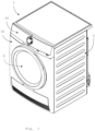
Figure 1 is a perspective view of a laundry drier according to the invention; -
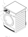
Figure 2 is a perspective view of a laundry drier offigure 1 with the drawer removed; -
Figure 3 is an enlarged detail ofFigure 2 ; -
Figure 4 is a schematic view of some components of a laundry drier according to the invention; -
Figure 5 is a schematic sectional view of some components of laundry drier according to the invention; -
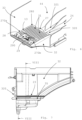
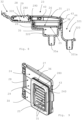
Figure 6 is a perspective view of a detail of a liquid loading unit installed in a laundry drier according to the invention; -
Figure 7 is a front view of the liquid loading unit offigure 6 ; -
Figure 8 is a cross section operated according to section plane VII-VII offigure 7 ; -
Figure 9 is a perspective view from below of a liquid loading unit of a laundry drier according to the invention, wherein the filter has not been represented; -
Figure 10 is a perspective view from above of a liquid loading unit of a laundry drier according to the invention, with the lid in the closed position; -
Figure 11 is a perspective view from above of a liquid loading unit offigure 10 , with the lid in the closed position; - In the figures same parts are indicated with the same reference numbers.
- In attached figures, a laundry drier according to the invention is identified by
number 1. - Advantageously, the laundry drier 1 illustrated in attached figures is a tumble drier of the "horizontal axis type"; it is however clear that the invention can be applied, without any substantial modification, also to tumble driers of the vertical axis" type, to washer-driers, both of the "horizontal axis" and of the "vertical axis" type, and also to "drying cabinets".
- The laundry drier 1 (being it a tumble drier, a washer-drier, or a drying cabinet) comprises a
casing 2, preferably parallelepiped, configured to be positioned on ahorizontal surface 3, for example the floor of a building, preferably bysuitable feet 4, one or more of which can have, advantageously, an adjustable height, so as to adapt to a possible not perfect planarity of thehorizontal surface 3. - The laundry drier 1 comprises a
laundry treating compartment 5, mounted within thecasing 2, wherein laundry to be treated, not illustrated, can be loaded, advantageously via an access opening, also not illustrated, obtained in thecasing 2, and selectively closable by a loading/unloading door 6, preferably hinged to thecasing 2. - Advantageously, in case, like in the advantageous example of attached figures, the laundry drier 1 is a tumble drier, the
laundry treating compartment 5 is adrum 50, preferably containing one ormore lifter 51, rotatably housed within thecasing 2, and preferably rotatably supported byrollers 7, which are advantageously pivoted to a supportingstructure 8, static with respect to thecasing 2. - If the laundry drier 1 is a washer-drier, not illustrated, the
casing 2 also houses a washing tub, not illustrated, preferably suspended within thecasing 2 through springs and dumpers, also not illustrated, in which thedrum 50 is rotatably contained. - If the laundry drier 1 is a drying cabinet, not illustrated, the
laundry treating compartment 5 is simply a hollow compartment, defined within thecabinet 2, preferably provided with clothes hanger bars or hooks, both not illustrated, for hanging the laundry. - The laundry drier 1 advantageously comprises a a
drying system 9, comprising anair conduit 10, passing through and comprising thelaundry treating compartment 5, anair moving device 11, for example a fan orblower 110, generating, when operated, an air flow 12 (schematically illustrated infigures 4 and5 with arrows) which passes through theair conduit 10, anair heating device 13, positioned at least partially within theair conduit 10 so as to heat theair flow 12 before it passes through thelaundry treating compartment 5. - In an advantageous embodiment, for example the one illustrated in attached figures, in which the laundry drier 1 is a tumble drier, and the
laundry treating compartment 5 is adrum 50, theair conduit 10 advantageously comprises such a drum 50 (which is preferably arranged to be crossed from itsrear side 50a to itsfront side 50b by the air flow 12), and a plurality ofair ducts 52, one or more of which are preferably at least partially comprised in the supportingstructure 8 and/or in the loading/unloading door 6, and which are fluidly connected to thedrum 50 in such a way to supply theair flow 12 within thedrum 50 and to receive theair flow 12 exiting the latter. - In an advantageous embodiment, like for example in the one illustrated in attached figures, the
air conduit 10 is arranged in such a way to circulate theairflow 12 through thelaundry treating compartment 5; in this case, moistureladen air flow 12 exiting thelaundry treating compartment 5 is deprived of moisture in amoisture condensing device 14, and then it is heated again by theair heating device 13 before being pumped again into thelaundry treating compartment 5. - In this case, preferably, the
drying system 9 can also advantageously comprise alint filter 15, arranged in theair conduit 10, downstream of thelaundry treating compartment 5, for trapping lint or fluff released from the laundry and carried out of thelaundry treating compartment 5 by theair flow 12. - In a further advantageous embodiment, not illustrated, the
air conduit 10 is arranged in such a way that theair flow 12, after passing through thelaundry treating compartment 5, instead of being circulated is discharged to the external environment, optionally after being at least partially deprived of moisture in amoisture condensing device 14. - Preferably, the
moisture condensing device 14 is a heat exchanger arranged for being lapped by theair flow 12 and for causing an heat exchange between such anair flow 12 and a cold fluid (e.g. cold air or a refrigerant) passing through the heat exchanger, so as to cool down theair flow 12 and to condense the moisture contained therein. - Advantageously, the
moisture condensing device 14 is fluidly connected to acondensate container 140 receiving condensate removed from theair flow 12 by themoisture condensing device 14; for example, thecondensate container 140 can be atray 141 positioned below themoisture condensing device 14, so as to collect condensed-moisture drops falling by gravity from the latter. - In an advantageous embodiment, not illustrated, the
air heating device 13 is or comprises one or more electric heaters, not illustrated, positioned at least partially within theair conduit 10 so as to heat theair flow 12 passing on it. - In a further advantageous embodiment, like the one illustrated in attached figures, the
heating device 13 and themoisture condensing device 14 are part of anheat pump system 16, advantageously comprising a compressor, not illustrated, an expansion valve, also not illustrated, twoheat exchangers 17a, 17b (one operating as a condenser, and the other as an evaporator), and conduits, not illustrated, fluidly connecting such elements in a closed circuit; a refrigerant flows through the compressor, the condenser 17a, the expansion valve and the evaporator 17b, and through the conduits connecting these to one another. The refrigerant releases heat to theair flow 12 by means of the condenser 17a, which is therefore theheating device 13, and extracts heat and humidity from theair flow 12 by means of the evaporator 17b, which is therefore themoisture condensing device 14. The compressor converts electromechanical power to thermal power by compressing the refrigerant in the refrigerant circuit. - The laundry drier 1 comprises also a
steam generator 18 comprising a mainliquid reservoir 19, wherein a liquid can be loaded, and aliquid heating device 20 operable for generating heat to heat a liquid contained in and/or coming from the mainliquid reservoir 19, so as to produce steam which is delivered to thelaundry treating compartment 5 via asteam delivery conduit 21 fluidly connecting thesteam generator 18 to thelaundry treating compartment 5. - In an advantageous embodiment, not illustrated, the
liquid heating device 20 comprises one or more electric heaters, housed within the mainliquid reservoir 19 for heating a liquid contained therein, and producing steam which is driven towards and released into the inner volume of thelaundry treating compartment 5 via thesteam delivery conduit 21. - In a further advantageous embodiment, like for example the one illustrated in attached figures, the
liquid heating device 20 is external to the mainliquid reservoir 19, and it is arranged in such a way to heat the liquid after it exits the mainliquid reservoir 19. - For example, like in the advantageous embodiment illustrated in
figure 4 , theliquid heating device 20 can comprise aheating conduit 200, fluidly connecting the mainliquid reservoir 19 to thesteam delivery conduit 21, and one or more electric heaters, not illustrated, contained in such aheating conduit 200; the one or more electric heaters heat the liquid flowing out of the mainliquid reservoir 19 and received by theheating conduit 200, converting such a liquid into steam, before it reaches thesteam delivery conduit 21 via which it is released, in the form of steam, into thelaundry treating compartment 5. - Advantageously, the
steam delivery conduit 21 releases the steam into thelaundry treating compartment 5 via anozzle 22. - According to the invention, the laundry drier 1 comprises a
liquid loading unit 23, by which a liquid (e.g. water or water mixed with an additive, for example a fragrance) can be manually loaded into the mainliquid reservoir 19; theliquid loading unit 23 comprises a liquid receivingelement 24, having anoutlet opening 25, fluidly connected or connectable to the mainliquid reservoir 19, and afilter 26, preferably, but not necessarily, removable, provided upstream to or at theoutlet opening 25, so as to filter a liquid flowing out of the liquid receivingelement 24 via theoutlet opening 25. - Preferably, the
liquid receiving element 24 is box shaped and hollow. - The
liquid loading unit 23 comprises alid 27, movable with respect to theliquid receiving element 24 between a closed position (as the one illustrated for example infigures 2 ,3 ,4 ,6 ,7 ,8 ,9 ,10 ), in which thelid 27 at least partially overlaps thefilter 26, preventing a user from reaching the latter, and an opened position (as the one illustrated for example infigure 10 ) allowing a user to reach thefilter 26. - It is underlined that the expression "reaching" the filter has to be construed as accessing the
filter 26 in a way suitable for completely cleaning the latter and/or for grasping the filter in such a way to be able to remove it, if removable, for cleaning or replacing it. - In the same way, the expression "preventing a user from reaching" the
filter 26 has to be construed as avoiding that a user can access thefilter 26 in such a way to completely clean the latter, or to grasp such afilter 26 in such a way to be able to remove it, if removable, for cleaning or replacing it. - In an advantageous embodiment, like the one illustrated in attached figures, the
lid 27 is hinged to theliquid receiving element 24, so as to be moved from the closed to the opened position, and vice-versa, by a rotation; preferably, like in the embodiment illustrated in attached figures, thelid 27 is, in a plan view, substantially U-shaped, so as to define twoparallel arms liquid receiving element 24. - In a further advantageous embodiment, not illustrated, the
lid 27 is slidably connected to theliquid receiving element 23, so as to be moved from the closed to the opened position, and vice-versa, by sliding on theliquid receiving element 24. - According to the invention, the
liquid loading unit 23 comprises one or more liquid loading openings allowing to manually load a liquid in theliquid receiving element 24 even when thelid 27 is in the closed position. - Advantageously, as for example in the advantageous embodiment illustrated in attached figures, the one or more liquid loading openings comprise a first liquid loading opening 28 provided at the liquid receiving
element 24 and fluidly connected to theoutlet opening 25 via afluid path 29 bypassing thelid 27 and passing through thefilter 26. - Preferably, the first
liquid loading opening 28 is provided in theliquid receiving element 24. - In an advantageous embodiment, like the one illustrated in attached figures, the
liquid receiving element 24 comprises anhopper 30, preferably rectangular or squared in a plan view, in which saidoutlet opening 25 and said firstliquid loading opening 28 are provided. - Advantageously, the
outlet opening 25 and the firstliquid loading opening 28 are fluidly connected to one another, preferably via a connectingconduit 290 provided at least partially in thehopper 30; advantageously, the connectingconduit 290 is or is part of thefluid path 29 fluidly connecting the first liquid loading opening 28 to theoutlet opening 25. - In an advantageous embodiment, like the one illustrated in attached figures, the first
liquid loading opening 28 is delimited by aperimeter frame 28a, protruding substantially perpendicularly from thehopper 30, and having anopening 280 fluidly connecting the firstliquid opening 28 to the connectingconduit 290. - In an advantageous embodiment, like the one illustrated in attached figures, in which the
lid 27 is substantially U-shaped and hinged at the second ends of itsparallel arms liquid receiving element 24, the firstliquid loading opening 28 is preferably, but not necessarily, arranged in such a way to be positioned between the twoparallel arms lid 27 when the latter is in the closed position. - In a further advantageous embodiment, not illustrated, the first
liquid loading opening 28 and theoutlet opening 25 are defined by two portions of a same aperture provided in theliquid receiving element 24; preferably, in this advantageous embodiment, the firstliquid loading opening 28, theoutlet opening 25, and thefilter 26 are reciprocally positioned in such a way that, when thelid 27 is in the closed position, it at least partially overlaps thefilter 26 and delimits the first loading opening 28 in such a way to prevent a user from reaching thefilter 26 via thefirst loading aperture 28. - In a further advantageous embodiment, the
filter 26 overlaps the outlet opening 25 so that thefilter 26 and theoutlet opening 25 are aligned with each other, while the firstliquid loading opening 25 is misaligned with respect to thefilter 26 and theoutlet opening 25; this misalignment is such that a user, when thelid 27 is in the closed position, is prevented from reaching, or accessing, thefilter 26 in a way suitable for completely cleaning and/or grasping the latter. - In a further advantageous embodiment, the dimensions of the first
liquid loading opening 28 are so small that a user cannot insert a finger within such a first liquid loading opening 28 far enough for reaching the filter, which, when thelid 27 is in the closed position, prevents a user from reaching, or accessing, thefilter 26 in a way suitable for completely cleaning and/or grasping the latter. - In another advantageous embodiment, between the first
liquid loading opening 28 and thefilter 25 there is a separating element, not illustrated, interposed between such a firstliquid loading opening 28 and thefilter 26 for preventing a user, when thelid 27 is in the closed position, from reaching, or accessing, thefilter 26 in a way suitable for completely cleaning and/or grasping the latter. - In an advantageous embodiment, in addition (like in the advantageous embodiment illustrated in attached figures) or as an alternative to the first
liquid loading opening 28, theliquid loading unit 23 comprises one or more secondliquid loading openings 31, provided in thelid 27, via which a liquid can be loaded in theliquid receiving element 23 and go to theoutlet opening 25, passing through thelid 27, when the latter is in said closed position. - Preferably, the second
liquid loading openings 31 have an elongated shape. - In an advantageous embodiment, like the one illustrated in attached figures, in which the
lid 27 is substantially U-shaped and hinged at the second ends of itsparallel arms liquid receiving element 24, one or more of the secondliquid loading openings 31 are arranged on one or both the twoparallel arms lid 27. - In an advantageous embodiment, like the one illustrated in attached figures, the
laundry dryer 1 comprises a box-shapedseat 32, accessible from the external, preferably from afront side 33, of thecasing 2, suitable for removably housing adrawer 34. - The box-shaped
seat 32 comprises, in itsbottom region 320, ahousing 35 fluidly connected to the mainliquid reservoir 19, in which theliquid loading unit 23 is at least partially housed in a permanent or removable way. Advantageously, the bottom of thehousing 35 is funnel shaped, and provided with afirst draining opening 35a, fluidly connected to the mainliquid reservoir 19. - Preferably a sealing
element 36 is arranged in thehousing 35 or in aportion 240 of the loading unit 23 (preferably of the liquid receiving element 24) positioned, or that can be positioned, in thehousing 35, so as to be interposed between thehousing 36 and theportion 240 for achieving a watertight coupling thereof. - In an advantageous embodiment, like for example the one illustrated in attached figures, the
fluid path 29 fluidly connecting the first liquid loading opening 28 to theoutlet opening 25 bypassing thelid 27 and passing through thefilter 26, is defined partially in theliquid receiving element 24 and partially by part of thebottom region 320 of the box-shapedseat 32 corresponding to thehousing 35 wherein theliquid loading unit 23 is at least partially housed in a permanent or removable way. - In an advantageous embodiment, like for example the one illustrated in attached figures, the
laundry dryer 1 comprises apumping system 37, fluidly connecting thecondensate container 140 to theliquid loading unit 23; thepumping system 37 advantageously comprises apump 38 that sucks a liquid from thecondensate container 140 and pumps it to theliquid loading unit 23 via apiping system 39 having acondensate outlet 40 provided at theliquid loading unit 23, and/or to aliquid collecting reservoir 41 of the laundry drier 1, fluidly connected or connectable to thepiping system 39. - Advantageously, like in the embodiment illustrated in attached figures, the
condensate outlet 40 is provided at theliquid loading unit 23 upstream of thefilter 26, so that the liquid coming from thepumping system 37 is filtered before exiting theoutlet opening 25 and going to the mainliquid reservoir 19. - Advantageously, the
condensate outlet 40 of thepiping system 39 enters theliquid loading unit 23 via anopening 40a, preferably obtained in thelid 27, or in theliquid receiving element 23, or partially in thelid 27 and partially in theliquid receiving element 23. - In an advantageous embodiment, the
piping system 39 comprises afirst valve 42 operable to selectively direct a liquid, sucked by thepump 38 from thecondensate container 140, to theliquid collecting reservoir 41 and/or to theliquid loading unit 23. - In another advantageous embodiment, in place of the
first valve 42, a piping branch connector is used to split or drive liquid sucked by thepump 38 from thecondensate container 140, to theliquid collecting reservoir 41 and/or to theliquid loading unit 23. - Preferably, like in the advantageous embodiment illustrated in attached figures, the
liquid collecting reservoir 41 is mounted in thedrawer 34, so as to be removably housed in the box-shapedseat 32, which allows to remove end empty such aliquid collecting reservoir 41 when needed. - In an advantageous embodiment, like for example the one illustrated in attached figures, the
liquid loading unit 23 comprises anoverflow opening 43 for discharging outside of the liquid loading unit 23 a liquid contained within theliquid loading unit 23, and exceeding a prefixed level, so as to prevent this liquid from flowing back through the one or moreliquid loading openings - Advantageously, such a prefixed level is, with respect to a
horizontal surface 3, for example the floor of a building, on which the laundry drier 1 is positioned, lower than the level of the inlet of the one or moreliquid loading openings - Advantageously, the
overflow opening 43 is comprised in thelid 27 and/or in theliquid receiving element 24, or it is defined by a gap between thelid 27 and the liquid receivingelement 28. - Advantageously, the
overflow opening 43 is fluidly connected to thecondensate container 140 in such a way that a liquid flowing out of theoverflow opening 43 is drained to thecondensate container 140. - Preferably, the
overflow opening 43 is fluidly connected to thecondensate container 140 through anoverflow reservoir 44, receiving a liquid flowing out of theoverflow opening 43, and fluidly connected to thecondensate container 140 so as to drain to the latter the liquid received from theoverflow opening 43. - In an advantageous embodiment, like in the one illustrated in attached figures, the
overflow reservoir 44 is advantageously defined by aportion 321 of thebottom region 320 of the box-shapedseat 32; preferably, such aportion 321 is funnel shaped, and provided, at its bottom, with asecond draining opening 321a, fluidly connected to thecondensate container 140. - In an advantageous embodiment, like the one illustrated in attached figures, the
overflow opening 43 is positioned at a prefixed level that prevents the flow back of a liquid from theliquid loading unit 23 to thecondensate outlet 40 of thepiping system 39. - Advantageously, such a prefixed level is, with respect to a
horizontal surface 3, for example the floor of a building, on which the laundry drier 1 is positioned, lower than thecondensate outlet 40 of thepiping system 39. - In an advantageous embodiment, like the one illustrated in attached figures, the
laundry dryer 1 comprises adrain conduit 45, selectively fluidly connecting themain reservoir 19 to the external of thelaundry dryer 1, so as to allow selectively draining outside the laundry drier 1 a liquid contained in themain reservoir 19. - In an advantageous embodiment, like the one illustrated in attached figures, in which the
liquid heating device 20 is external to the mainliquid reservoir 19 and comprises aheating conduit 200, fluidly connecting the mainliquid reservoir 19 to thesteam delivery conduit 21, and one or more electric heaters, not illustrated, contained in such aheating conduit 200, thedrain conduit 45 can be advantageously fluidly connected to the mainliquid reservoir 19, preferably, by asecond valve 46, selectively directing a liquid coming from the mainliquid reservoir 19 to theheating conduit 200 and/or to thedrain conduit 46. - In another advantageous embodiment, in place of the
second valve 46, a piping branch connector is used to split or drive liquid coming from the mainliquid reservoir 19 toward theheating conduit 200 and/or to thedrain conduit 46. - The functioning of the laundry drier 1 according to the invention is described the following.
- In order to manually load a liquid, for example water or water mixed with an additive, in the main
liquid reservoir 19 of thesteam generator 18, a user has simply to pour such a liquid in one or more of the one or moreliquid loading openings liquid loading unit 23, without the need of opening thelid 27. - The
lid 27 has to be opened only in order to reach thefilter 26, for example for cleaning it or removing it, if removable, for its maintenance or replacement. - In the advantageous embodiment in which both the first and the second liquid loading openings are provided, if the user, while trying to pour the liquid, for example, only in the first
liquid loading opening 28, spills some liquid over thelid 27, the second loading opening 31 allow the spilled liquid to enter the liquid receivingelement 24 and to go to the mainliquid reservoir 19 through theoutlet opening 25, so that such a spilled liquid is not wasted. - During the drying process, if the laundry drier 1 is provided with the
moisture condensing device 14, the latter removes moisture from theair flow 12 exiting thelaundry treating compartment 5; such a moisture is collected in thecondensate container 140, from which it is taken, by thepumping system 37, to theliquid loading unit 23, and optionally to theliquid collecting reservoir 41. From theliquid loading unit 23, the moisture is taken to the mainliquid reservoir 19, where it can be used for producing steam. - The
filter 26 of theliquid loading unit 23 grants that the liquid provided to the mainliquid reservoir 19 is free from dirt, and in particular from lint or fluff that can be present in theair flow 12 and released in the condensed moisture that is collected in thecondensate container 140. - The
liquid loading unit 23 is housed in thehousing 35, it is necessary to remove thedrawer 34 from the box-shapedseat 32 before being able to load a liquid in theliquid loading unit 23. Differently from the cited prior art, since the loading of liquid in theliquid loading unit 23 can be done with thelid 27 in the closed position, the risk that thedrawer 34 is inserted in the box-shapedseat 32 with thelid 27 in the open position, and therefore the risk of damaging thelid 27 and/or the drawer, is very low. - It is seen therefore how the invention achieves the proposed aim and objects, since, thanks to the possibility to load a liquid in the liquid loading unit without opening the lid, the liquid loading process is easy and quick.
- Moreover, the advantageous embodiment in which both the first and the second liquid loading openings are provided, allows reducing the liquid wastage, since liquid spilled over the lid while being manually poured in the first liquid loading opening can enter the liquid loading element, and go to the outlet opening, via the second loading opening.
- In addition, in the advantageous embodiment in which the liquid loading unit is housed in a housing obtained in the box-shaped seat wherein a drawer can be removably received, the possibility of loading the liquid without opening the lid allows reducing the risk of introducing the drawer in the box-shaped seat with the lid in the open position, and therefore the risk of damaging the lid and/or the drawer.
- Moreover, the advantageously embodiment in which the laundry drier is provided with the moisture condensing device, and the condensed moisture is taken to the liquid loading unit by the pumping system, from which it is taken to the main liquid reservoir passing through the filter, allows reducing the liquid consumption for producing steam, and ensures at the same time that the liquid provided to the main liquid reservoir is free from dirt, and in particular form lint and fluff, that could damage the steam generator.
-
- 1 laundry drier
- 2 casing
- 3 horizontal surface
- 4 feet
- 5 laundry treating compartment
- 6 loading/unloading door
- 7 rollers
- 8 supporting structure
- 9 drying system
- 10 air conduit
- 11 air moving device
- 12 air flow
- 13 air heating device
- 14 moisture condensing device
- 15 lint filter
- 16 heat pump system
- 17a, 17b heat exchanger (condenser, evaporator)
- 18 steam generator
- 19 main liquid reservoir
- 20 liquid heating device
- 21 steam delivery conduit
- 22 nozzle
- 23 liquid loading unit
- 24 liquid receiving element
- 25 outlet opening
- 26 filter
- 27 lid
- 28 first liquid loading opening
- 28a perimeter frame
- 29 fluid path
- 30 hopper
- 31 second liquid loading opening
- 32 box-shaped seat
- 33 front side
- 34 drawer
- 35 housing
- 35a first draining opening
- 36 sealing element
- 37 pumping system
- 38 pump
- 39 piping system
- 40 condensate outlet
- 40a opening
- 41 liquid collecting reservoir
- 42 first valve
- 43 overflow opening
- 44 overflow reservoir
- 45 drain conduit
- 46 second valve
- 50 drum
- 50a rear side
- 50b front side
- 51 lifters
- 52 air ducts
- 110 fan or blower
- 140 condensate container
- 141 tray
- 200 heating conduit
- 240 portion
- 270a, 270b arms
- 271 crosspiece
- 290 connecting conduit
- 320 bottom region
- 321 portion
- 321a second draining opening
Claims (14)
- A laundry dryer (1) comprising:- a casing (2);- a laundry treating compartment (5), mounted within said casing (2), in which laundry to be treated can be loaded;- a drying system (9) comprising an air conduit (10), passing through and comprising said laundry treating compartment (5), an air moving device (11), generating, when operated, an air flow (12) which passes through said air conduit (10), an air heating device (13), positioned at least partially within said air conduit (10) so as to heat said air flow (12) before it passes through said laundry treating compartment (5);- a steam generator (18) comprising a main liquid reservoir (19), in which a liquid can be loaded, and a liquid heating device (20) operable for generating heat to heat a liquid contained in and/or coming from said main liquid reservoir (19), so as to produce steam that is delivered to said laundry treating compartment (5) via a steam delivery conduit (21) fluidly connecting said steam generator (6) to said laundry treating compartment (5);- a liquid loading unit (23) comprising a liquid receiving element (24), having an outlet opening (25), fluidly connected or connectable to said main liquid reservoir (19), and a filter (26), provided upstream to or at said outlet opening (25), so as to filter a liquid flowing out of said liquid receiving element (24) via said outlet opening (25),wherein said liquid loading unit (23) comprises a lid (27), movable with respect to said liquid receiving element (24) between a closed position, in which said lid (27) at least partially overlaps said filter (26), preventing a user from reaching the latter, and an opened position allowing a user to reach said filter (26),wherein said liquid loading unit (23) comprises one or more liquid loading openings (28, 31) allowing to manually load a liquid in said liquid receiving element (24) even when said lid (27) is in said closed position,characterized in thatsaid laundry dryer (1) comprises a box-shaped seat (32), accessible from the external of said casing (2) and suitable for removably receiving a drawer (320), comprising, in its bottom region (320), a housing (35), fluidly connected to said main liquid reservoir (19), and in which said liquid loading unit (23) is at least partially housed in a permanent or removable way.
- A laundry dryer (1), as in claim 1, wherein said one or more liquid loading openings (28, 31) comprise a first liquid loading opening (28) provided at said liquid receiving element (24) and fluidly connected to said outlet opening (25) via a fluid path (29) bypassing said lid (27) and passing through said filter (26).
- A laundry dryer (1), as in claim 2, wherein said first liquid loading opening (28) is provided in said liquid receiving element (24).
- A laundry dryer (1), as in claim 2 or 3, wherein said liquid receiving element (24) comprises an hopper (30), in which said outlet opening (25) and said first liquid loading opening (28) are provided, wherein said outlet opening (25) and said first liquid loading opening (28) are fluidly connected to one another.
- A laundry dryer (1), as in one or more of the previous claims, wherein said liquid loading unit (23) comprises a plurality of liquid loading openings (28, 31) which comprise one or more second liquid loading openings (31), provided in said lid (27), via which a liquid is loaded in said liquid receiving element (24) and go to said outlet opening (25), passing through said lid (27), when the latter is in said closed position.
- A laundry dryer (1), as in one or more of the previous claims, comprising a sealing element (36) arranged in said housing (35) or in a portion (240) of said liquid loading unit (23) being configured to be positioned in said housing (35), so as to be interposed between said housing (35) and said portion (240) for achieving a watertight coupling thereof.
- A laundry dryer (1), as in one or more of the previous claims, comprising a moisture condensing device (14) positioned at least partially within said air conduit (10), downstream of said laundry treating compartment (5), so as to condense and remove moisture contained in said air flow (12), said moisture condensing device (14) being fluidly connected to a condensate container (140) receiving condensate removed from said air flow (12) by said moisture condensing device (14).
- A laundry dryer (1), as in claim 7 comprising a pumping system (37), fluidly connecting said condensate container (140) to said liquid loading unit (23), comprising a pump (38) that sucks a liquid from said condensate container (140) and pumps it to said liquid loading unit (23) via a piping system (39) having a condensate outlet (40) provided at said liquid loading unit (23), and/or to a liquid collecting reservoir (41) of said laundry drier (1), fluidly connected or connectable to said piping system (39).
- A laundry dryer (1), as in claim 8, wherein said condensate outlet (40) is provided at said liquid loading unit (23) upstream of said filter (26).
- A laundry dryer (1), as in one or more of the previous claims, wherein said liquid loading unit (23) comprises an overflow opening (43) for discharging outside of said liquid loading unit (23) a liquid contained within said liquid loading unit (23) and exceeding a prefixed level, so as to prevent said liquid from flowing back through said one or more liquid loading openings (28, 31).
- A laundry dryer (1), as in claim 10, wherein said overflow opening (43) is comprised in said lid (27) and/or in said liquid receiving element (24), or it is defined by a gap between said lid (27) and said liquid receiving element (24).
- A laundry dryer (1), as in claim 10 or 11, when depending on claim 7, wherein said overflow opening (43) is fluidly connected to said condensate container (140) in such a way that a liquid flowing out of said overflow opening (43) is drained to said condensate container (140).
- Laundry drier (1) as in one or more of the previous claims, wherein said lid (27) is hinged to said liquid receiving element (24), so as to be moved from said closed to said opened position, and vice-versa, by a rotation, or said lid (27) is slidably connected to said liquid receiving element (24), so as to be moved from said closed to said opened position, and vice-versa, by sliding on said liquid receiving element (24).
- Method for loading a liquid to be converted into steam in a laundry drier (1) according to one or more of the previous claims, comprising the steps of first removing said drawer (34) from the box-shaped seat (32) and then loading a liquid to be converted into steam in said liquid loading unit (23) of said laundry drier (1) via one or more of said one or more liquid loading openings (28, 31) of said liquid loading unit (23), while said lid (27) is in said closed position.
Priority Applications (4)
| Application Number | Priority Date | Filing Date | Title |
|---|---|---|---|
| EP21151487.2A EP4029980B1 (en) | 2021-01-14 | 2021-01-14 | A laundry dryer provided with a steam generator and a corresponding method |
| PL21151487.2T PL4029980T3 (en) | 2021-01-14 | 2021-01-14 | A laundry dryer provided with a steam generator and a corresponding method |
| AU2021266298A AU2021266298A1 (en) | 2021-01-14 | 2021-11-11 | A laundry dryer provided with a steam generator |
| CN202210042637.1A CN114763668A (en) | 2021-01-14 | 2022-01-14 | Clothes dryer provided with steam generator |
Applications Claiming Priority (1)
| Application Number | Priority Date | Filing Date | Title |
|---|---|---|---|
| EP21151487.2A EP4029980B1 (en) | 2021-01-14 | 2021-01-14 | A laundry dryer provided with a steam generator and a corresponding method |
Publications (2)
| Publication Number | Publication Date |
|---|---|
| EP4029980A1 EP4029980A1 (en) | 2022-07-20 |
| EP4029980B1 true EP4029980B1 (en) | 2024-07-24 |
Family
ID=74183076
Family Applications (1)
| Application Number | Title | Priority Date | Filing Date |
|---|---|---|---|
| EP21151487.2A Active EP4029980B1 (en) | 2021-01-14 | 2021-01-14 | A laundry dryer provided with a steam generator and a corresponding method |
Country Status (4)
| Country | Link |
|---|---|
| EP (1) | EP4029980B1 (en) |
| CN (1) | CN114763668A (en) |
| AU (1) | AU2021266298A1 (en) |
| PL (1) | PL4029980T3 (en) |
Family Cites Families (8)
| Publication number | Priority date | Publication date | Assignee | Title |
|---|---|---|---|---|
| KR101203840B1 (en) * | 2006-12-14 | 2012-11-21 | 엘지전자 주식회사 | laundry device and control method of the same |
| KR100921460B1 (en) * | 2007-11-02 | 2009-10-13 | 엘지전자 주식회사 | dryer |
| EP2666902A1 (en) * | 2012-05-22 | 2013-11-27 | Electrolux Home Products Corporation N.V. | Laundry dryer and method of operating a laundry dryer |
| WO2014075848A1 (en) | 2012-11-13 | 2014-05-22 | Arcelik Anonim Sirketi | A laundry washing and/or drying machine with a steam generator |
| KR102043197B1 (en) * | 2013-02-28 | 2019-11-11 | 엘지전자 주식회사 | Laundry Treating Apparatus |
| CN105518208B (en) * | 2013-04-17 | 2017-12-22 | 伊莱克斯家用电器股份公司 | clothes dryer |
| AU2013390336B2 (en) * | 2013-05-24 | 2018-09-27 | Electrolux Appliances Aktiebolag | Laundry dryer and method of operating a laundry dryer |
| EP3224401B1 (en) * | 2014-11-28 | 2018-09-05 | Arçelik Anonim Sirketi | A laundry dryer |
-
2021
- 2021-01-14 PL PL21151487.2T patent/PL4029980T3/en unknown
- 2021-01-14 EP EP21151487.2A patent/EP4029980B1/en active Active
- 2021-11-11 AU AU2021266298A patent/AU2021266298A1/en active Pending
-
2022
- 2022-01-14 CN CN202210042637.1A patent/CN114763668A/en active Pending
Also Published As
| Publication number | Publication date |
|---|---|
| PL4029980T3 (en) | 2024-11-25 |
| CN114763668A (en) | 2022-07-19 |
| EP4029980A1 (en) | 2022-07-20 |
| AU2021266298A1 (en) | 2022-07-28 |
Similar Documents
| Publication | Publication Date | Title |
|---|---|---|
| EP3019657B1 (en) | Laundry dryer | |
| EP2199453B1 (en) | A household appliance | |
| EP2270274B2 (en) | Appliance for drying laundry | |
| US20110005276A1 (en) | Clothes treating apparatus | |
| ITMI990304A1 (en) | COMBINED WASHING MACHINE | |
| CA2659256A1 (en) | Multiple laundry treating machine | |
| EP2471998B1 (en) | Appliance for drying laundry | |
| US20090126414A1 (en) | Fabric treating machine | |
| US9003837B2 (en) | Apparatus including a plurality of spray distribution nozzles for washing articles without agitation | |
| EP2669417A1 (en) | Washer-dryer machine with a heat pump | |
| AU2007277599A1 (en) | Multiple laundry treating machine and control method thereof | |
| CN105492675A (en) | Laundry appliance having a water filter | |
| CN107109765A (en) | Clothes treatment device with heat exchanger and condensate collector | |
| CN103221606B (en) | Method for removing odorous substances from laundry in a washer-dryer and washer-dryer suitable for the method | |
| SI25814A (en) | Condensation dryer | |
| KR20210019867A (en) | Apparatus for treating clothes | |
| KR102505495B1 (en) | Apparatus for laundry treatment | |
| WO2020046246A2 (en) | Ultrasonic laundry cleaning and drying module | |
| RU2446239C2 (en) | Household dryer for linen | |
| KR20110123330A (en) | dryer | |
| EP4029980B1 (en) | A laundry dryer provided with a steam generator and a corresponding method | |
| WO2024149220A1 (en) | Drainage device of laundry apparatus | |
| EP3791016B1 (en) | Laundry dryer | |
| CN102575406B (en) | Auxiliary components for washing machines | |
| KR20110123333A (en) | dryer |
Legal Events
| Date | Code | Title | Description |
|---|---|---|---|
| PUAI | Public reference made under article 153(3) epc to a published international application that has entered the european phase |
Free format text: ORIGINAL CODE: 0009012 |
|
| STAA | Information on the status of an ep patent application or granted ep patent |
Free format text: STATUS: THE APPLICATION HAS BEEN PUBLISHED |
|
| AK | Designated contracting states |
Kind code of ref document: A1 Designated state(s): AL AT BE BG CH CY CZ DE DK EE ES FI FR GB GR HR HU IE IS IT LI LT LU LV MC MK MT NL NO PL PT RO RS SE SI SK SM TR |
|
| STAA | Information on the status of an ep patent application or granted ep patent |
Free format text: STATUS: REQUEST FOR EXAMINATION WAS MADE |
|
| 17P | Request for examination filed |
Effective date: 20230120 |
|
| RBV | Designated contracting states (corrected) |
Designated state(s): AL AT BE BG CH CY CZ DE DK EE ES FI FR GB GR HR HU IE IS IT LI LT LU LV MC MK MT NL NO PL PT RO RS SE SI SK SM TR |
|
| GRAP | Despatch of communication of intention to grant a patent |
Free format text: ORIGINAL CODE: EPIDOSNIGR1 |
|
| STAA | Information on the status of an ep patent application or granted ep patent |
Free format text: STATUS: GRANT OF PATENT IS INTENDED |
|
| RIC1 | Information provided on ipc code assigned before grant |
Ipc: D06F 58/24 20060101ALN20240208BHEP Ipc: D06F 58/20 20060101AFI20240208BHEP |
|
| INTG | Intention to grant announced |
Effective date: 20240221 |
|
| RIN1 | Information on inventor provided before grant (corrected) |
Inventor name: MISSIO, GABRIELE Inventor name: QUARONI, ALBERTO Inventor name: BISON, ALBERTO |
|
| P01 | Opt-out of the competence of the unified patent court (upc) registered |
Effective date: 20240306 |
|
| GRAS | Grant fee paid |
Free format text: ORIGINAL CODE: EPIDOSNIGR3 |
|
| GRAA | (expected) grant |
Free format text: ORIGINAL CODE: 0009210 |
|
| STAA | Information on the status of an ep patent application or granted ep patent |
Free format text: STATUS: THE PATENT HAS BEEN GRANTED |
|
| AK | Designated contracting states |
Kind code of ref document: B1 Designated state(s): AL AT BE BG CH CY CZ DE DK EE ES FI FR GB GR HR HU IE IS IT LI LT LU LV MC MK MT NL NO PL PT RO RS SE SI SK SM TR |
|
| REG | Reference to a national code |
Ref country code: GB Ref legal event code: FG4D |
|
| REG | Reference to a national code |
Ref country code: CH Ref legal event code: EP |
|
| REG | Reference to a national code |
Ref country code: IE Ref legal event code: FG4D Ref country code: DE Ref legal event code: R096 Ref document number: 602021015980 Country of ref document: DE |
|
| REG | Reference to a national code |
Ref country code: LT Ref legal event code: MG9D |
|
| REG | Reference to a national code |
Ref country code: NL Ref legal event code: MP Effective date: 20240724 |
|
| PG25 | Lapsed in a contracting state [announced via postgrant information from national office to epo] |
Ref country code: PT Free format text: LAPSE BECAUSE OF FAILURE TO SUBMIT A TRANSLATION OF THE DESCRIPTION OR TO PAY THE FEE WITHIN THE PRESCRIBED TIME-LIMIT Effective date: 20241125 |
|
| REG | Reference to a national code |
Ref country code: AT Ref legal event code: MK05 Ref document number: 1706414 Country of ref document: AT Kind code of ref document: T Effective date: 20240724 |
|
| PG25 | Lapsed in a contracting state [announced via postgrant information from national office to epo] |
Ref country code: NL Free format text: LAPSE BECAUSE OF FAILURE TO SUBMIT A TRANSLATION OF THE DESCRIPTION OR TO PAY THE FEE WITHIN THE PRESCRIBED TIME-LIMIT Effective date: 20240724 |
|
| PG25 | Lapsed in a contracting state [announced via postgrant information from national office to epo] |
Ref country code: PT Free format text: LAPSE BECAUSE OF FAILURE TO SUBMIT A TRANSLATION OF THE DESCRIPTION OR TO PAY THE FEE WITHIN THE PRESCRIBED TIME-LIMIT Effective date: 20241125 Ref country code: NL Free format text: LAPSE BECAUSE OF FAILURE TO SUBMIT A TRANSLATION OF THE DESCRIPTION OR TO PAY THE FEE WITHIN THE PRESCRIBED TIME-LIMIT Effective date: 20240724 |
|
| PG25 | Lapsed in a contracting state [announced via postgrant information from national office to epo] |
Ref country code: NO Free format text: LAPSE BECAUSE OF FAILURE TO SUBMIT A TRANSLATION OF THE DESCRIPTION OR TO PAY THE FEE WITHIN THE PRESCRIBED TIME-LIMIT Effective date: 20241024 |
|
| PG25 | Lapsed in a contracting state [announced via postgrant information from national office to epo] |
Ref country code: FI Free format text: LAPSE BECAUSE OF FAILURE TO SUBMIT A TRANSLATION OF THE DESCRIPTION OR TO PAY THE FEE WITHIN THE PRESCRIBED TIME-LIMIT Effective date: 20240724 Ref country code: GR Free format text: LAPSE BECAUSE OF FAILURE TO SUBMIT A TRANSLATION OF THE DESCRIPTION OR TO PAY THE FEE WITHIN THE PRESCRIBED TIME-LIMIT Effective date: 20241025 |
|
| PG25 | Lapsed in a contracting state [announced via postgrant information from national office to epo] |
Ref country code: BG Free format text: LAPSE BECAUSE OF FAILURE TO SUBMIT A TRANSLATION OF THE DESCRIPTION OR TO PAY THE FEE WITHIN THE PRESCRIBED TIME-LIMIT Effective date: 20240724 |
|
| PG25 | Lapsed in a contracting state [announced via postgrant information from national office to epo] |
Ref country code: LV Free format text: LAPSE BECAUSE OF FAILURE TO SUBMIT A TRANSLATION OF THE DESCRIPTION OR TO PAY THE FEE WITHIN THE PRESCRIBED TIME-LIMIT Effective date: 20240724 |
|
| PG25 | Lapsed in a contracting state [announced via postgrant information from national office to epo] |
Ref country code: AT Free format text: LAPSE BECAUSE OF FAILURE TO SUBMIT A TRANSLATION OF THE DESCRIPTION OR TO PAY THE FEE WITHIN THE PRESCRIBED TIME-LIMIT Effective date: 20240724 Ref country code: IS Free format text: LAPSE BECAUSE OF FAILURE TO SUBMIT A TRANSLATION OF THE DESCRIPTION OR TO PAY THE FEE WITHIN THE PRESCRIBED TIME-LIMIT Effective date: 20241124 |
|
| PG25 | Lapsed in a contracting state [announced via postgrant information from national office to epo] |
Ref country code: HR Free format text: LAPSE BECAUSE OF FAILURE TO SUBMIT A TRANSLATION OF THE DESCRIPTION OR TO PAY THE FEE WITHIN THE PRESCRIBED TIME-LIMIT Effective date: 20240724 |
|
| PG25 | Lapsed in a contracting state [announced via postgrant information from national office to epo] |
Ref country code: RS Free format text: LAPSE BECAUSE OF FAILURE TO SUBMIT A TRANSLATION OF THE DESCRIPTION OR TO PAY THE FEE WITHIN THE PRESCRIBED TIME-LIMIT Effective date: 20241024 Ref country code: ES Free format text: LAPSE BECAUSE OF FAILURE TO SUBMIT A TRANSLATION OF THE DESCRIPTION OR TO PAY THE FEE WITHIN THE PRESCRIBED TIME-LIMIT Effective date: 20240724 |
|
| PG25 | Lapsed in a contracting state [announced via postgrant information from national office to epo] |
Ref country code: RS Free format text: LAPSE BECAUSE OF FAILURE TO SUBMIT A TRANSLATION OF THE DESCRIPTION OR TO PAY THE FEE WITHIN THE PRESCRIBED TIME-LIMIT Effective date: 20241024 Ref country code: NO Free format text: LAPSE BECAUSE OF FAILURE TO SUBMIT A TRANSLATION OF THE DESCRIPTION OR TO PAY THE FEE WITHIN THE PRESCRIBED TIME-LIMIT Effective date: 20241024 Ref country code: LV Free format text: LAPSE BECAUSE OF FAILURE TO SUBMIT A TRANSLATION OF THE DESCRIPTION OR TO PAY THE FEE WITHIN THE PRESCRIBED TIME-LIMIT Effective date: 20240724 Ref country code: IS Free format text: LAPSE BECAUSE OF FAILURE TO SUBMIT A TRANSLATION OF THE DESCRIPTION OR TO PAY THE FEE WITHIN THE PRESCRIBED TIME-LIMIT Effective date: 20241124 Ref country code: HR Free format text: LAPSE BECAUSE OF FAILURE TO SUBMIT A TRANSLATION OF THE DESCRIPTION OR TO PAY THE FEE WITHIN THE PRESCRIBED TIME-LIMIT Effective date: 20240724 Ref country code: GR Free format text: LAPSE BECAUSE OF FAILURE TO SUBMIT A TRANSLATION OF THE DESCRIPTION OR TO PAY THE FEE WITHIN THE PRESCRIBED TIME-LIMIT Effective date: 20241025 Ref country code: FI Free format text: LAPSE BECAUSE OF FAILURE TO SUBMIT A TRANSLATION OF THE DESCRIPTION OR TO PAY THE FEE WITHIN THE PRESCRIBED TIME-LIMIT Effective date: 20240724 Ref country code: ES Free format text: LAPSE BECAUSE OF FAILURE TO SUBMIT A TRANSLATION OF THE DESCRIPTION OR TO PAY THE FEE WITHIN THE PRESCRIBED TIME-LIMIT Effective date: 20240724 Ref country code: BG Free format text: LAPSE BECAUSE OF FAILURE TO SUBMIT A TRANSLATION OF THE DESCRIPTION OR TO PAY THE FEE WITHIN THE PRESCRIBED TIME-LIMIT Effective date: 20240724 Ref country code: AT Free format text: LAPSE BECAUSE OF FAILURE TO SUBMIT A TRANSLATION OF THE DESCRIPTION OR TO PAY THE FEE WITHIN THE PRESCRIBED TIME-LIMIT Effective date: 20240724 |
|
| PG25 | Lapsed in a contracting state [announced via postgrant information from national office to epo] |
Ref country code: SM Free format text: LAPSE BECAUSE OF FAILURE TO SUBMIT A TRANSLATION OF THE DESCRIPTION OR TO PAY THE FEE WITHIN THE PRESCRIBED TIME-LIMIT Effective date: 20240724 Ref country code: DK Free format text: LAPSE BECAUSE OF FAILURE TO SUBMIT A TRANSLATION OF THE DESCRIPTION OR TO PAY THE FEE WITHIN THE PRESCRIBED TIME-LIMIT Effective date: 20240724 Ref country code: RO Free format text: LAPSE BECAUSE OF FAILURE TO SUBMIT A TRANSLATION OF THE DESCRIPTION OR TO PAY THE FEE WITHIN THE PRESCRIBED TIME-LIMIT Effective date: 20240724 |
|
| PG25 | Lapsed in a contracting state [announced via postgrant information from national office to epo] |
Ref country code: EE Free format text: LAPSE BECAUSE OF FAILURE TO SUBMIT A TRANSLATION OF THE DESCRIPTION OR TO PAY THE FEE WITHIN THE PRESCRIBED TIME-LIMIT Effective date: 20240724 |
|
| PG25 | Lapsed in a contracting state [announced via postgrant information from national office to epo] |
Ref country code: CZ Free format text: LAPSE BECAUSE OF FAILURE TO SUBMIT A TRANSLATION OF THE DESCRIPTION OR TO PAY THE FEE WITHIN THE PRESCRIBED TIME-LIMIT Effective date: 20240724 |
|
| PGFP | Annual fee paid to national office [announced via postgrant information from national office to epo] |
Ref country code: PL Payment date: 20250109 Year of fee payment: 5 |
|
| REG | Reference to a national code |
Ref country code: DE Ref legal event code: R097 Ref document number: 602021015980 Country of ref document: DE |
|
| PG25 | Lapsed in a contracting state [announced via postgrant information from national office to epo] |
Ref country code: IT Free format text: LAPSE BECAUSE OF FAILURE TO SUBMIT A TRANSLATION OF THE DESCRIPTION OR TO PAY THE FEE WITHIN THE PRESCRIBED TIME-LIMIT Effective date: 20240724 Ref country code: SK Free format text: LAPSE BECAUSE OF FAILURE TO SUBMIT A TRANSLATION OF THE DESCRIPTION OR TO PAY THE FEE WITHIN THE PRESCRIBED TIME-LIMIT Effective date: 20240724 |
|
| PLBE | No opposition filed within time limit |
Free format text: ORIGINAL CODE: 0009261 |
|
| STAA | Information on the status of an ep patent application or granted ep patent |
Free format text: STATUS: NO OPPOSITION FILED WITHIN TIME LIMIT |
|
| 26N | No opposition filed |
Effective date: 20250425 |
|
| REG | Reference to a national code |
Ref country code: CH Ref legal event code: PL |
|
| PG25 | Lapsed in a contracting state [announced via postgrant information from national office to epo] |
Ref country code: SE Free format text: LAPSE BECAUSE OF FAILURE TO SUBMIT A TRANSLATION OF THE DESCRIPTION OR TO PAY THE FEE WITHIN THE PRESCRIBED TIME-LIMIT Effective date: 20240724 |
|
| PG25 | Lapsed in a contracting state [announced via postgrant information from national office to epo] |
Ref country code: LU Free format text: LAPSE BECAUSE OF NON-PAYMENT OF DUE FEES Effective date: 20250114 Ref country code: MC Free format text: LAPSE BECAUSE OF FAILURE TO SUBMIT A TRANSLATION OF THE DESCRIPTION OR TO PAY THE FEE WITHIN THE PRESCRIBED TIME-LIMIT Effective date: 20240724 |
|
| PG25 | Lapsed in a contracting state [announced via postgrant information from national office to epo] |
Ref country code: BE Free format text: LAPSE BECAUSE OF NON-PAYMENT OF DUE FEES Effective date: 20250131 |
|
| PG25 | Lapsed in a contracting state [announced via postgrant information from national office to epo] |
Ref country code: CH Free format text: LAPSE BECAUSE OF NON-PAYMENT OF DUE FEES Effective date: 20250131 |
|
| REG | Reference to a national code |
Ref country code: BE Ref legal event code: MM Effective date: 20250131 |
|
| PG25 | Lapsed in a contracting state [announced via postgrant information from national office to epo] |
Ref country code: IE Free format text: LAPSE BECAUSE OF NON-PAYMENT OF DUE FEES Effective date: 20250114 |
|
| PGFP | Annual fee paid to national office [announced via postgrant information from national office to epo] |
Ref country code: GB Payment date: 20260126 Year of fee payment: 6 |
|
| PGFP | Annual fee paid to national office [announced via postgrant information from national office to epo] |
Ref country code: DE Payment date: 20260127 Year of fee payment: 6 |
|
| PGFP | Annual fee paid to national office [announced via postgrant information from national office to epo] |
Ref country code: FR Payment date: 20260127 Year of fee payment: 6 |