EP4029788A1 - Systems and methods of determining a capacity of storage bins - Google Patents
Systems and methods of determining a capacity of storage bins Download PDFInfo
- Publication number
- EP4029788A1 EP4029788A1 EP22150417.8A EP22150417A EP4029788A1 EP 4029788 A1 EP4029788 A1 EP 4029788A1 EP 22150417 A EP22150417 A EP 22150417A EP 4029788 A1 EP4029788 A1 EP 4029788A1
- Authority
- EP
- European Patent Office
- Prior art keywords
- voltage output
- sensors
- capacity
- storage bin
- used capacity
- Prior art date
- Legal status (The legal status is an assumption and is not a legal conclusion. Google has not performed a legal analysis and makes no representation as to the accuracy of the status listed.)
- Granted
Links
Images




Classifications
-
- G—PHYSICS
- G01—MEASURING; TESTING
- G01F—MEASURING VOLUME, VOLUME FLOW, MASS FLOW OR LIQUID LEVEL; METERING BY VOLUME
- G01F17/00—Methods or apparatus for determining the capacity of containers or cavities, or the volume of solid bodies
-
- B—PERFORMING OPERATIONS; TRANSPORTING
- B64—AIRCRAFT; AVIATION; COSMONAUTICS
- B64D—EQUIPMENT FOR FITTING IN OR TO AIRCRAFT; FLIGHT SUITS; PARACHUTES; ARRANGEMENT OR MOUNTING OF POWER PLANTS OR PROPULSION TRANSMISSIONS IN AIRCRAFT
- B64D11/00—Passenger or crew accommodation; Flight-deck installations not otherwise provided for
-
- B—PERFORMING OPERATIONS; TRANSPORTING
- B64—AIRCRAFT; AVIATION; COSMONAUTICS
- B64D—EQUIPMENT FOR FITTING IN OR TO AIRCRAFT; FLIGHT SUITS; PARACHUTES; ARRANGEMENT OR MOUNTING OF POWER PLANTS OR PROPULSION TRANSMISSIONS IN AIRCRAFT
- B64D11/00—Passenger or crew accommodation; Flight-deck installations not otherwise provided for
- B64D11/003—Stowage devices for passengers' personal luggage
-
- B—PERFORMING OPERATIONS; TRANSPORTING
- B64—AIRCRAFT; AVIATION; COSMONAUTICS
- B64D—EQUIPMENT FOR FITTING IN OR TO AIRCRAFT; FLIGHT SUITS; PARACHUTES; ARRANGEMENT OR MOUNTING OF POWER PLANTS OR PROPULSION TRANSMISSIONS IN AIRCRAFT
- B64D45/00—Aircraft indicators or protectors not otherwise provided for
-
- G—PHYSICS
- G01—MEASURING; TESTING
- G01S—RADIO DIRECTION-FINDING; RADIO NAVIGATION; DETERMINING DISTANCE OR VELOCITY BY USE OF RADIO WAVES; LOCATING OR PRESENCE-DETECTING BY USE OF THE REFLECTION OR RERADIATION OF RADIO WAVES; ANALOGOUS ARRANGEMENTS USING OTHER WAVES
- G01S17/00—Systems using the reflection or reradiation of electromagnetic waves other than radio waves, e.g. lidar systems
- G01S17/87—Combinations of systems using electromagnetic waves other than radio waves
-
- G—PHYSICS
- G01—MEASURING; TESTING
- G01S—RADIO DIRECTION-FINDING; RADIO NAVIGATION; DETERMINING DISTANCE OR VELOCITY BY USE OF RADIO WAVES; LOCATING OR PRESENCE-DETECTING BY USE OF THE REFLECTION OR RERADIATION OF RADIO WAVES; ANALOGOUS ARRANGEMENTS USING OTHER WAVES
- G01S17/00—Systems using the reflection or reradiation of electromagnetic waves other than radio waves, e.g. lidar systems
- G01S17/88—Lidar systems specially adapted for specific applications
-
- B—PERFORMING OPERATIONS; TRANSPORTING
- B64—AIRCRAFT; AVIATION; COSMONAUTICS
- B64D—EQUIPMENT FOR FITTING IN OR TO AIRCRAFT; FLIGHT SUITS; PARACHUTES; ARRANGEMENT OR MOUNTING OF POWER PLANTS OR PROPULSION TRANSMISSIONS IN AIRCRAFT
- B64D45/00—Aircraft indicators or protectors not otherwise provided for
- B64D2045/007—Indicators or signs in the cabin, e.g. exit signs or seat numbering
Definitions
- the field relates generally to overhead storage bin assemblies and, more specifically, to systems and methods of determining and displaying a used capacity within overhead storage bins.
- Modern day flights are typically booked to full capacity, which makes overhead storage space a desired but limited commodity. As such, it may be difficult for later-boarding passengers to find sufficient or conveniently located overhead storage space for their carryon luggage.
- the overhead storage space may be at full capacity before all the carryon luggage has been stowed, which causes frustration for the passengers and delay in the boarding process.
- available overhead space may be located several rows away from a passenger's seat, which may cause delays in embarking and disembarking from the aircraft. Additional delay may also be a result of the time it takes to individually inspect storage bins to identify remaining overhead storage space.
- the system includes a plurality of sensors positioned within the storage bin. Each sensor is configured to determine a used capacity within a portion of the storage bin, and generate a voltage output based on the determined used capacity, wherein the plurality of sensors is configured to generate an aggregate voltage output based on the voltage output of each sensor.
- a controller is in communication with the plurality of sensors. The controller is configured to receive the aggregate voltage output from the plurality of sensors, determine a minimum voltage output and a maximum voltage output of the plurality of sensors, and determine a total used capacity of the storage bin as a function of the aggregate voltage output, the minimum voltage output, and the maximum voltage output.
- a vehicle including a passenger cabin, a plurality of storage bins coupled within the passenger cabin, and a plurality of sensors positioned within each storage bin.
- Each sensor is configured to determine a used capacity within a portion of the storage bin, and generate a voltage output based on the determined used capacity, wherein the plurality of sensors is configured to generate an aggregate voltage output based on the voltage output of each sensor.
- a controller is in communication with the plurality of sensors. The controller is configured to receive the aggregate voltage output from the plurality of sensors, determine a minimum voltage output and a maximum voltage output of the plurality of sensors, and determine a total used capacity of the storage bin as a function of the aggregate voltage output, the minimum voltage output, and the maximum voltage output.
- the method includes determining, with one of a plurality of sensors within the storage bin, a used capacity within a portion of the storage bin. Each sensor is configured to generate a voltage output based on the determined used capacity, and the plurality of sensors is configured to generate an aggregate voltage output based on the voltage output of each sensor.
- the method also includes receiving the aggregate voltage output from the plurality of sensors, determining a minimum voltage output and a maximum voltage output of the plurality of sensors, and determining a total used capacity of the storage bin as a function of the aggregate voltage output, the minimum voltage output, and the maximum voltage output.
- Examples described below include systems and methods of determining and displaying a used capacity within overhead storage bins. More specifically, the system described herein includes a plurality of sensors within each storage bin for determining a used capacity within each storage bin. The system uses an algorithm that correlates voltage readings received from the sensors into available space. The voltage readings may be aggregated to determine a total used capacity within each storage bin, and an indication of the total used capacity may be provided to either the passengers or flight crew of an aircraft via a display. As such, the passengers or flight crew are able to quickly determine the location of available overhead storage space when boarding the aircraft.
- FIG. 1 is an internal view of an example aircraft 100 (i.e., a vehicle).
- aircraft 100 includes a passenger cabin 102 and a plurality of overhead storage bins 104 coupled within passenger cabin 102.
- Passenger cabin 102 also includes a seating area 106 and an aisle 108 extending along passenger cabin 102 for providing access to the plurality of overhead storage bins 104 and seating area 106.
- the plurality of overhead storage bins 104 are selectively positioned between an open position and a closed position for receiving and stowing one or more objects (e.g., luggage) therein.
- object e.g., luggage
- While described in the context of a passenger aircraft, application of the systems and methods described herein is not limited to passenger aircraft.
- the systems and methods described herein may be implemented with any cargo-carrying vehicle such as, but not limited to, buses and trains.
- FIG. 2 is a block diagram illustrating an example system 110 for determining a capacity within storage bins 104.
- System 110 includes a plurality of sensors 112 (e.g. 112-1 through 112-12) positioned within each storage bin 104.
- Sensors 112 may be any device capable of determining a used capacity within at least a portion of storage bin 104. Accordingly, the plurality of sensors 112 may be arranged to enable a total used capacity of storage bin 104 to be determined.
- sensors 112 are time-of-flight camera sensors configured to emit a light signal, and determine the distance of an obstruction from the respective sensor 112 based on a time it takes for a return signal, derived from the emitted light signal, to be received at sensor 112.
- Alternative sensors 112 include, but are not limited to, pressure and/or resistive force sensors.
- sensors 112 generate a voltage output based on an analysis of the return signal.
- the voltage output generated by a respective sensor 112 is variable based on a distance between the respective sensor 112 and the obstruction (e.g., an opposing side wall of storage bin 104 or a piece of luggage), and the voltage outputs of the plurality of sensors 112 within a respective storage bin 104 may be used to determine a total used capacity therein.
- System 110 further includes a display device 114 configured to display the total used capacity, such as to the passengers or flight crew of aircraft 100.
- a display device 116 is associated with each storage bin 104, and the respective display device 114 displays the total used capacity of its associated storage bin 104.
- display devices 116 are light-emitting diode (LED) indicators including a plurality of LEDs (not shown) that may be selectively activated for displaying one of a plurality of capacity indicators for the associated storage bin 104.
- the capacity indicators may be defined by different colors that each correspond to a determined capacity level, or defined by a number of LEDs activated based on the determined capacity level.
- a display device 118 may be a distinct device that is positioned remotely from the plurality of storage bins 104. More specifically, display device 118 may receive and display the total used capacity of each storage bin 104 within aircraft 100. For example, display device 118 may be at an entryway of passenger cabin 102 such that passengers can view potentially available overhead storage space as they are boarding aircraft 100, may be a flight attendant panel, or may be a passenger's mobile device having an application downloaded thereon.
- System 110 further includes an activation device 120 configured to control the operational status of system 110 (i.e., sensors 112 and display devices 114).
- Activation device 120 enables system 110 to be activated only when appropriate, such as during boarding of aircraft 100. Accordingly, in some examples, activation device 120 monitors an operational status of one or more components of aircraft 100 that may be linked to an appropriate activation time.
- activation device 120 may be a sensor that monitors the opening and closing of a respective storage bin 104, a weight-on-wheels sensor, a sensor that monitors the opening and closing of a cabin door, or may monitor a power generation state of aircraft 100 (i.e., system 110 activated when ground or APU power is provided).
- system 110 may be activated and deactivated manually. Accordingly, selectively activating system 110 facilitates preserving energy.
- a controller 122 is in communication with sensors 112, display devices 114, and activation device 120.
- Controller 122 includes a memory 124 and a processor 126, including hardware and software, coupled to memory 124 for executing programmed instructions.
- Processor 126 may include one or more processing units (e.g., in a multi-core configuration) and/or include a cryptographic accelerator (not shown).
- Controller 122 is programmable to perform one or more operations described herein by programming memory 124 and/or processor 126.
- processor 126 may be programmed by encoding an operation as executable instructions and providing the executable instructions in memory 124.
- Processor 126 may include, but is not limited to, a general purpose central processing unit (CPU), a microcontroller, a microprocessor, a reduced instruction set computer (RISC) processor, an open media application platform (OMAP), an application specific integrated circuit (ASIC), a programmable logic circuit (PLC), and/or any other circuit or processor capable of executing the functions described herein.
- the methods described herein may be encoded as executable instructions embodied in a computer-readable medium including, without limitation, a storage device and/or a memory device. Such instructions, when executed by processor 126, cause processor 126 to perform at least a portion of the functions described herein.
- the above examples are for example purposes only, and thus are not intended to limit in any way the definition and/or meaning of the term processor.
- Memory 124 is one or more devices that enable information such as executable instructions and/or other data to be stored and retrieved.
- Memory 124 may include one or more computer-readable media, such as, without limitation, dynamic random access memory (DRAM), synchronous dynamic random access memory (SDRAM), static random access memory (SRAM), a solid state disk, and/or a hard disk.
- DRAM dynamic random access memory
- SDRAM synchronous dynamic random access memory
- SRAM static random access memory
- Solid state disk and/or a hard disk.
- Memory 124 may be configured to store, without limitation, executable instructions, operating systems, applications, resources, installation scripts and/or any other type of data suitable for use with the methods and systems described herein.
- Non-transitory memory 124 Instructions for operating systems and applications are located in a functional form on non-transitory memory 124 for execution by processor 126 to perform one or more of the processes described herein.
- These instructions in the different implementations may be embodied on different physical or tangible computer-readable media, such as memory 124 or another memory, such as a computer-readable media (not shown), which may include, without limitation, a flash drive and/or thumb drive.
- instructions may be located in a functional form on non-transitory computer-readable media, which may include, without limitation, smart-media (SM) memory, compact flash (CF) memory, secure digital (SD) memory, memory stick (MS) memory, multimedia card (MMC) memory, embedded-multimedia card (e-MMC), and micro-drive memory.
- the computer-readable media may be selectively insertable and/or removable from controller 122 to permit access and/or execution by processor 126. In an alternative implementation, the computer-readable media is not removable.
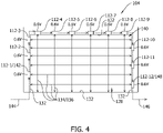
- FIGS. 3-5 illustrate sensors 112 positioned within storage bin 104.
- storage bin 104 includes an interior 128 and an opening 130 that provides access to interior 128.
- Interior 128 is defined by a plurality of side walls 132, and sensors 112 are coupled to one or more of side walls 132 and arranged in an array across side walls 132.
- each sensor 112 emits a signal 134 therefrom, and receives a return signal 136 derived from the bounce back of signal 134 from an obstruction such as an opposing side wall 132 or luggage 138 (shown in FIG. 5 ) positioned within interior 128. Accordingly, as shown in FIGS.
- signals 134 from sensors 112 define a two-dimensional sensing grid 140 across interior 128 of storage bin 104.
- sensors 112 are coupled only to one side wall 132, such as a top side wall 132 of storage bin 104 to define the two-dimensional sensing grid 140 from the vertically-aligned signals 134 emitted therefrom.
- a first sensor 142 of the plurality of sensors 112 is provided with ground power 144 (e.g., 5 VDC), and the plurality of sensors 112 (1-12) are electrically coupled to each other in series. Accordingly, a bias signal may be cascaded across the plurality of sensors 112 to enable an aggregate voltage output 146 to be generated and output by the array of sensors 112.
- aggregate voltage output 146 is a single output signal transmitted in analog from a last sensor 148 of those coupled in series in the array. As such, the complexity and computing power required to analyze aggregate voltage output 146 is reduced.
- analog refers to a continuous, not discrete, voltage value.
- each sensor 112 provides its own digital output signal for analysis, such as to an I 2 C multiplexer and PC board.
- digital refers to a discrete, not continuous, voltage value.
- each sensor 112 When powered, each sensor 112 generates a voltage output that is variable within a range defined by a minimum voltage output and a maximum voltage output. Variation in the voltage output is dependent on the sensed distance between a respective sensor 112 and an object. For example, sensors 112 may be calibrated to generate the minimum voltage output when storage bin 104 is empty and the space within the field of view of each sensor 112 is unobstructed (e.g., when the sensed distance is determined to be at a threshold level). Alternatively, the voltage output generated by each sensor 112 increases when luggage 137, 138 is positioned within storage bin 104 to obstruct the field of view of at least one sensor 112 (i.e., the voltage output increases up to the maximum voltage output as the sensed distance decreases). For example, the maximum voltage output is generated when luggage 137, 138 is sized to reduce the sensed distance to less than a threshold level.
- controller 122 receives aggregate voltage output 146 from the plurality of sensors 112. Controller 122 also determines a total minimum voltage output and a total maximum voltage output of the plurality of sensors 112, and determines a total used capacity of the storage bin as a function of aggregate voltage output 146, the total minimum voltage output, and the total maximum voltage output. The total maximum and minimum voltage outputs are determined as a function of the number of sensors 112 within system 110.
- system 110 includes twelve sensors 112 each having a minimum voltage output of about 0.6 V (or about 0.6 V) and a maximum voltage output of 3.6 V (or about 3.6 V), such that the total minimum voltage output of the plurality of sensors 112 is 7.2 V (or about 7.2 V) and the total maximum voltage output is 43.2 V (or about 43.2 V).
- luggage 137, 138 are positioned within interior 128 of storage bin 104. Luggage 137 is sized to obstruct the field of view of some, but not all, of the plurality of sensors 112 in the array. Similarly, luggage 138 is sized to obstruct the field of view of some, but not all, of the plurality of sensors 112 in the array.
- each sensor 112 generates its own respective voltage output based on the sensed distance between a respective sensor 112 and an object (e.g., side wall 132, or luggage 137, 138), as described above.
- display devices 114 display one of a plurality of capacity indicators for the associated storage bin 104, wherein the distinct capacity indicators correspond to a determined capacity level within storage bin 104.
- a plurality of capacity threshold ranges may be defined by and/or stored within controller 122.
- controller 122 determines the total used capacity of storage bin 104, compares the determined total used capacity to the capacity threshold ranges, and controls operation of an associated display device 114 based on the comparison.
- An example capacity threshold scheme may include capacity threshold ranges such as a ⁇ 50% used capacity range, a 50-90% used capacity range, and a >90% used capacity range.
- a distinct capacity indicator may correspond to each threshold range (e.g., a green indicator light for the ⁇ 50% used capacity range, a yellow indicator light for the 50-90% used capacity range, and a red indicator light for the >90% used capacity range). Accordingly, displaying the distinct capacity indicator enables passengers and the flight crew to quickly and easily determine the location of available overhead storage space.
- FIG. 6 is a flow diagram illustrating an example method 200 of determining a capacity within a storage bin.
- the method 200 includes determining 202, with one of a plurality of sensors within the storage bin, a used capacity within a portion of the storage bin. Each sensor is configured to generate (202A) a voltage output based on the determined used capacity, and the plurality of sensors is configured to generate 202B an aggregate voltage output based on the voltage output of each sensor.
- the method 200 also includes receiving 204 the aggregate voltage output from the plurality of sensors, determining 206 a minimum voltage output and a maximum voltage output of the plurality of sensors, and determining 208 a total used capacity of the storage bin as a function of the aggregate voltage output, the minimum voltage output, and the maximum voltage output.
- the method 200 also includes comparing 210 the total used capacity to a plurality of capacity threshold ranges that are each associated with a respective capacity indicator, and displaying 212, based on the comparison, the respective capacity indicator associated with one of the plurality of capacity threshold range
- a system for use in determining a capacity of a storage bin (104) comprises: a plurality of sensors (112) positioned within the storage bin (104), wherein each sensor (112) is configured to: determine (202) a used capacity within a portion of the storage bin (104); and generate (202A) a voltage output based on the determined used capacity, wherein the plurality of sensors (112) is configured to generate (202B) an aggregate voltage output based on the voltage output of each sensor (112); and a controller (122) in communication with the plurality of sensors (112), the controller (122) configured to: receive (204) the aggregate voltage output from the plurality of sensors (112); determine (206) a minimum voltage output and a maximum voltage output of the plurality of sensors (112); and determine (208) a total used capacity of the storage bin (104) as a function of the aggregate voltage output, the minimum voltage output, and the maximum voltage output.
- the plurality of sensors (112) are electrically coupled to each other in series to generate the aggregate voltage output in a single output signal.
- the plurality of sensors (112) is configured to transmit the single output signal in analog.
- the plurality of sensors (112) are arranged to define a two-dimensional sensing grid across an interior (128) of the storage bin (104).
- system of one of the earlier paragraphs further comprises a display device (114) in communication with the controller (122), wherein the display device (114) is configured to display the total used capacity of the storage bin (104).
- the controller (122) is further configured to compare the total used capacity to a plurality of capacity threshold ranges that are each associated with a respective capacity indicator, wherein the display device (114) is configured to display, based on the comparison, the respective capacity indicator associated with one of the plurality of capacity threshold ranges.
- each sensor (112) is a time-of-flight camera sensor (112).
- the controller (122) is configured to monitor a boarding status of a vehicle.
- the controller is configured to selectively activate at least one of the plurality of sensors (112) or the display device (114) based on the boarding status of the vehicle.
- a vehicle comprises: a passenger cabin (102); a plurality of storage bins (104) coupled within the passenger cabin (102); a plurality of sensors (112) positioned within each storage bin (104), wherein each sensor (112) is configured to: determine (202) a used capacity within a portion of the storage bin (104); and generate (202A) a voltage output based on the determined used capacity, wherein the plurality of sensors (112) is configured to generate (202B) an aggregate voltage output based on the voltage output of each sensor (112); and a controller (122) in communication with the plurality of sensors (112), the controller (122) configured to: receive (204) the aggregate voltage output from the plurality of sensors (112); determine (206) a minimum voltage output and a maximum voltage output of the plurality of sensors (112); and determine (208) a total used capacity of the storage bin (104) as a function of the aggregate voltage output, the minimum voltage output, and the maximum voltage output.
- the plurality of sensors (112) are electrically coupled to each other in series to generate the aggregate voltage output in a single output signal.
- the plurality of sensors (112) is configured to transmit the single output signal in analog.
- each bin comprises an interior (128) and an opening (130) that provides access to the interior (128), wherein the plurality of sensors (112) are arranged to define a two-dimensional sensing grid across the interior (128) of a respective storage bin (104).
- the vehicle of one of the earlier paragraphs further comprising a display device (114) associated with each storage bin (104), wherein the display device (114) is configured to display the total used capacity of the associated storage bin (104).
- the controller (122) is configured to monitor a boarding status of the vehicle, and is configured to selectively activate at least one of the plurality of sensors (112) or the display device (114) based on the boarding status of the vehicle.
- each sensor (112) is a time-of-flight camera sensor (112)
- a method (200) of determining a capacity of a storage bin (104) comprises: determining (202), with one of a plurality of sensors (112) within the storage bin (104), a used capacity within a portion of the storage bin (104), wherein each sensor (112) is configured to generate (202A) a voltage output based on the determined used capacity, and wherein the plurality of sensors (112) is configured to generate (202B) an aggregate voltage output based on the voltage output of each sensor (112); receiving (204) the aggregate voltage output from the plurality of sensors (112); determining (206) a minimum voltage output and a maximum voltage output of the plurality of sensors (112); and determining (208) a total used capacity of the storage bin (104) as a function of the aggregate voltage output, the minimum voltage output, and the maximum voltage output.
- determining a total used capacity comprises quantifying the total used capacity as a function of a difference between the aggregate voltage output and the minimum voltage output, and as a function of the difference divided by the maximum voltage output.
- receiving the aggregate voltage output comprises receiving a single output signal in analog.
- the method of one of the earlier paragraphs further comprising displaying (210), on a display device (114), the total used capacity of the associated storage bin (104).
- the method of one of the earlier paragraphs further comprises: monitoring a boarding status of a vehicle; and selectively activating at least one of the plurality of sensors (112) or the display device (114) based on the boarding status of the vehicle.
- the method of one of the earlier paragraphs further comprises: comparing the total used capacity to a plurality of capacity threshold ranges that are each associated with a respective capacity indicator; and displaying, on the display device (114) based on the comparison, the respective capacity indicator associated with one of the plurality of capacity threshold ranges.
Landscapes
- Engineering & Computer Science (AREA)
- Physics & Mathematics (AREA)
- Aviation & Aerospace Engineering (AREA)
- General Physics & Mathematics (AREA)
- Fluid Mechanics (AREA)
- Electromagnetism (AREA)
- Computer Networks & Wireless Communication (AREA)
- Radar, Positioning & Navigation (AREA)
- Remote Sensing (AREA)
- Geophysics And Detection Of Objects (AREA)
- Warehouses Or Storage Devices (AREA)
- Management, Administration, Business Operations System, And Electronic Commerce (AREA)
- Measurement Of Levels Of Liquids Or Fluent Solid Materials (AREA)
- Electric Propulsion And Braking For Vehicles (AREA)
Abstract
Description
- The field relates generally to overhead storage bin assemblies and, more specifically, to systems and methods of determining and displaying a used capacity within overhead storage bins.
- Modern day flights are typically booked to full capacity, which makes overhead storage space a desired but limited commodity. As such, it may be difficult for later-boarding passengers to find sufficient or conveniently located overhead storage space for their carryon luggage. For example, the overhead storage space may be at full capacity before all the carryon luggage has been stowed, which causes frustration for the passengers and delay in the boarding process. In some instances, available overhead space may be located several rows away from a passenger's seat, which may cause delays in embarking and disembarking from the aircraft. Additional delay may also be a result of the time it takes to individually inspect storage bins to identify remaining overhead storage space.
- This section is intended to introduce the reader to various examples of art that may be related to various examples of the disclosure, which are described and/or claimed below. This discussion is believed to be helpful in providing the reader with background information to facilitate a better understanding of the various examples of the present disclosure. Accordingly, it should be understood that these statements are to be read in this light, and not as admissions of prior art.
- There is described a system for use in determining a capacity of a storage bin. The system includes a plurality of sensors positioned within the storage bin. Each sensor is configured to determine a used capacity within a portion of the storage bin, and generate a voltage output based on the determined used capacity, wherein the plurality of sensors is configured to generate an aggregate voltage output based on the voltage output of each sensor. A controller is in communication with the plurality of sensors. The controller is configured to receive the aggregate voltage output from the plurality of sensors, determine a minimum voltage output and a maximum voltage output of the plurality of sensors, and determine a total used capacity of the storage bin as a function of the aggregate voltage output, the minimum voltage output, and the maximum voltage output.
- There is also described a vehicle including a passenger cabin, a plurality of storage bins coupled within the passenger cabin, and a plurality of sensors positioned within each storage bin. Each sensor is configured to determine a used capacity within a portion of the storage bin, and generate a voltage output based on the determined used capacity, wherein the plurality of sensors is configured to generate an aggregate voltage output based on the voltage output of each sensor. A controller is in communication with the plurality of sensors. The controller is configured to receive the aggregate voltage output from the plurality of sensors, determine a minimum voltage output and a maximum voltage output of the plurality of sensors, and determine a total used capacity of the storage bin as a function of the aggregate voltage output, the minimum voltage output, and the maximum voltage output.
- There is also described the a method of determining a capacity of a storage bin. The method includes determining, with one of a plurality of sensors within the storage bin, a used capacity within a portion of the storage bin. Each sensor is configured to generate a voltage output based on the determined used capacity, and the plurality of sensors is configured to generate an aggregate voltage output based on the voltage output of each sensor. The method also includes receiving the aggregate voltage output from the plurality of sensors, determining a minimum voltage output and a maximum voltage output of the plurality of sensors, and determining a total used capacity of the storage bin as a function of the aggregate voltage output, the minimum voltage output, and the maximum voltage output.
- Various refinements exist of the features noted in relation to the above-mentioned examples of the present disclosure. Further features may also be incorporated in the above-mentioned examples of the present disclosure as well. These refinements and additional features may exist individually or in any combination. For instance, various features discussed below in relation to any of the illustrated examples of the present disclosure may be incorporated into any of the above-described examples of the present disclosure, alone or in any combination.
-
-
FIG. 1 is an internal view of an aircraft. -
FIG. 2 is a block diagram illustrating a system for determining a capacity within a storage bin. -
FIG. 3 is a perspective view of a storage bin that may be used in the aircraft shown inFIG. 1 . -
FIG. 4 is a schematic interior view of the storage bin shown inFIG. 3 . -
FIG. 5 is a schematic interior view of the storage bin shown inFIG. 3 , the bin having luggage stored therein. -
FIG. 6 is a flow diagram illustrating a method of determining a capacity within a storage bin. - Corresponding reference characters indicate corresponding parts throughout the drawings.
- Examples described below include systems and methods of determining and displaying a used capacity within overhead storage bins. More specifically, the system described herein includes a plurality of sensors within each storage bin for determining a used capacity within each storage bin. The system uses an algorithm that correlates voltage readings received from the sensors into available space. The voltage readings may be aggregated to determine a total used capacity within each storage bin, and an indication of the total used capacity may be provided to either the passengers or flight crew of an aircraft via a display. As such, the passengers or flight crew are able to quickly determine the location of available overhead storage space when boarding the aircraft.
- As used herein, an element or step recited in the singular and preceded with the word "a" or "an" should be understood as not excluding plural elements or steps, unless such exclusion is explicitly recited. Furthermore, references to "example" of the present disclosure are not intended to be interpreted as excluding the existence of additional examples that also incorporate the recited features.
-
FIG. 1 is an internal view of an example aircraft 100 (i.e., a vehicle). In this and other examples,aircraft 100 includes apassenger cabin 102 and a plurality ofoverhead storage bins 104 coupled withinpassenger cabin 102.Passenger cabin 102 also includes aseating area 106 and anaisle 108 extending alongpassenger cabin 102 for providing access to the plurality ofoverhead storage bins 104 andseating area 106. The plurality ofoverhead storage bins 104 are selectively positioned between an open position and a closed position for receiving and stowing one or more objects (e.g., luggage) therein. While described in the context of a passenger aircraft, application of the systems and methods described herein is not limited to passenger aircraft. For example, the systems and methods described herein may be implemented with any cargo-carrying vehicle such as, but not limited to, buses and trains. -
FIG. 2 is a block diagram illustrating anexample system 110 for determining a capacity withinstorage bins 104.System 110 includes a plurality of sensors 112 (e.g. 112-1 through 112-12) positioned within eachstorage bin 104.Sensors 112 may be any device capable of determining a used capacity within at least a portion ofstorage bin 104. Accordingly, the plurality ofsensors 112 may be arranged to enable a total used capacity ofstorage bin 104 to be determined. In this and other examples,sensors 112 are time-of-flight camera sensors configured to emit a light signal, and determine the distance of an obstruction from therespective sensor 112 based on a time it takes for a return signal, derived from the emitted light signal, to be received atsensor 112.Alternative sensors 112 include, but are not limited to, pressure and/or resistive force sensors. - In operation,
sensors 112 generate a voltage output based on an analysis of the return signal. As will be explained in more detail below, the voltage output generated by arespective sensor 112 is variable based on a distance between therespective sensor 112 and the obstruction (e.g., an opposing side wall ofstorage bin 104 or a piece of luggage), and the voltage outputs of the plurality ofsensors 112 within arespective storage bin 104 may be used to determine a total used capacity therein. -
System 110 further includes adisplay device 114 configured to display the total used capacity, such as to the passengers or flight crew ofaircraft 100. In some examples, at least one display device 116 is associated with eachstorage bin 104, and therespective display device 114 displays the total used capacity of its associatedstorage bin 104. In this and other examples, display devices 116 are light-emitting diode (LED) indicators including a plurality of LEDs (not shown) that may be selectively activated for displaying one of a plurality of capacity indicators for the associatedstorage bin 104. For example, the capacity indicators may be defined by different colors that each correspond to a determined capacity level, or defined by a number of LEDs activated based on the determined capacity level. - Alternatively, or in addition to coupling a display device 116 to each
storage bin 104, a display device 118 may be a distinct device that is positioned remotely from the plurality ofstorage bins 104. More specifically, display device 118 may receive and display the total used capacity of eachstorage bin 104 withinaircraft 100. For example, display device 118 may be at an entryway ofpassenger cabin 102 such that passengers can view potentially available overhead storage space as they are boardingaircraft 100, may be a flight attendant panel, or may be a passenger's mobile device having an application downloaded thereon. -
System 110 further includes anactivation device 120 configured to control the operational status of system 110 (i.e.,sensors 112 and display devices 114).Activation device 120 enablessystem 110 to be activated only when appropriate, such as during boarding ofaircraft 100. Accordingly, in some examples,activation device 120 monitors an operational status of one or more components ofaircraft 100 that may be linked to an appropriate activation time. For example,activation device 120 may be a sensor that monitors the opening and closing of arespective storage bin 104, a weight-on-wheels sensor, a sensor that monitors the opening and closing of a cabin door, or may monitor a power generation state of aircraft 100 (i.e.,system 110 activated when ground or APU power is provided). Alternatively,system 110 may be activated and deactivated manually. Accordingly, selectively activatingsystem 110 facilitates preserving energy. - A
controller 122 is in communication withsensors 112,display devices 114, andactivation device 120.Controller 122 includes amemory 124 and aprocessor 126, including hardware and software, coupled tomemory 124 for executing programmed instructions.Processor 126 may include one or more processing units (e.g., in a multi-core configuration) and/or include a cryptographic accelerator (not shown).Controller 122 is programmable to perform one or more operations described herein byprogramming memory 124 and/orprocessor 126. For example,processor 126 may be programmed by encoding an operation as executable instructions and providing the executable instructions inmemory 124. -
Processor 126 may include, but is not limited to, a general purpose central processing unit (CPU), a microcontroller, a microprocessor, a reduced instruction set computer (RISC) processor, an open media application platform (OMAP), an application specific integrated circuit (ASIC), a programmable logic circuit (PLC), and/or any other circuit or processor capable of executing the functions described herein. The methods described herein may be encoded as executable instructions embodied in a computer-readable medium including, without limitation, a storage device and/or a memory device. Such instructions, when executed byprocessor 126,cause processor 126 to perform at least a portion of the functions described herein. The above examples are for example purposes only, and thus are not intended to limit in any way the definition and/or meaning of the term processor. -
Memory 124 is one or more devices that enable information such as executable instructions and/or other data to be stored and retrieved.Memory 124 may include one or more computer-readable media, such as, without limitation, dynamic random access memory (DRAM), synchronous dynamic random access memory (SDRAM), static random access memory (SRAM), a solid state disk, and/or a hard disk.Memory 124 may be configured to store, without limitation, executable instructions, operating systems, applications, resources, installation scripts and/or any other type of data suitable for use with the methods and systems described herein. - Instructions for operating systems and applications are located in a functional form on
non-transitory memory 124 for execution byprocessor 126 to perform one or more of the processes described herein. These instructions in the different implementations may be embodied on different physical or tangible computer-readable media, such asmemory 124 or another memory, such as a computer-readable media (not shown), which may include, without limitation, a flash drive and/or thumb drive. Further, instructions may be located in a functional form on non-transitory computer-readable media, which may include, without limitation, smart-media (SM) memory, compact flash (CF) memory, secure digital (SD) memory, memory stick (MS) memory, multimedia card (MMC) memory, embedded-multimedia card (e-MMC), and micro-drive memory. The computer-readable media may be selectively insertable and/or removable fromcontroller 122 to permit access and/or execution byprocessor 126. In an alternative implementation, the computer-readable media is not removable. -
FIGS. 3-5 illustratesensors 112 positioned withinstorage bin 104. Referring toFIG. 3 ,storage bin 104 includes an interior 128 and anopening 130 that provides access tointerior 128.Interior 128 is defined by a plurality ofside walls 132, andsensors 112 are coupled to one or more ofside walls 132 and arranged in an array acrossside walls 132. In this and other examples, eachsensor 112 emits a signal 134 therefrom, and receives a return signal 136 derived from the bounce back of signal 134 from an obstruction such as an opposingside wall 132 or luggage 138 (shown inFIG. 5 ) positioned withininterior 128. Accordingly, as shown inFIGS. 4 and5 , signals 134 fromsensors 112 define a two-dimensional sensing grid 140 acrossinterior 128 ofstorage bin 104. In alternative examples,sensors 112 are coupled only to oneside wall 132, such as atop side wall 132 ofstorage bin 104 to define the two-dimensional sensing grid 140 from the vertically-aligned signals 134 emitted therefrom. - As shown in
FIGS. 4 and5 , afirst sensor 142 of the plurality ofsensors 112 is provided with ground power 144 (e.g., 5 VDC), and the plurality of sensors 112 (1-12) are electrically coupled to each other in series. Accordingly, a bias signal may be cascaded across the plurality ofsensors 112 to enable anaggregate voltage output 146 to be generated and output by the array ofsensors 112. In some examples,aggregate voltage output 146 is a single output signal transmitted in analog from alast sensor 148 of those coupled in series in the array. As such, the complexity and computing power required to analyzeaggregate voltage output 146 is reduced. As used herein, analog refers to a continuous, not discrete, voltage value. In alternative examples, eachsensor 112 provides its own digital output signal for analysis, such as to an I2C multiplexer and Arduino board. As used herein, digital refers to a discrete, not continuous, voltage value. - When powered, each
sensor 112 generates a voltage output that is variable within a range defined by a minimum voltage output and a maximum voltage output. Variation in the voltage output is dependent on the sensed distance between arespective sensor 112 and an object. For example,sensors 112 may be calibrated to generate the minimum voltage output whenstorage bin 104 is empty and the space within the field of view of eachsensor 112 is unobstructed (e.g., when the sensed distance is determined to be at a threshold level). Alternatively, the voltage output generated by eachsensor 112 increases whenluggage storage bin 104 to obstruct the field of view of at least one sensor 112 (i.e., the voltage output increases up to the maximum voltage output as the sensed distance decreases). For example, the maximum voltage output is generated whenluggage - In operation,
controller 122 receivesaggregate voltage output 146 from the plurality ofsensors 112.Controller 122 also determines a total minimum voltage output and a total maximum voltage output of the plurality ofsensors 112, and determines a total used capacity of the storage bin as a function ofaggregate voltage output 146, the total minimum voltage output, and the total maximum voltage output. The total maximum and minimum voltage outputs are determined as a function of the number ofsensors 112 withinsystem 110. - In some examples,
system 110 includes twelvesensors 112 each having a minimum voltage output of about 0.6 V (or about 0.6 V) and a maximum voltage output of 3.6 V (or about 3.6 V), such that the total minimum voltage output of the plurality ofsensors 112 is 7.2 V (or about 7.2 V) and the total maximum voltage output is 43.2 V (or about 43.2 V). Referring toFIG. 5 ,luggage interior 128 ofstorage bin 104.Luggage 137 is sized to obstruct the field of view of some, but not all, of the plurality ofsensors 112 in the array. Similarly,luggage 138 is sized to obstruct the field of view of some, but not all, of the plurality ofsensors 112 in the array. As illustrated in the example shown inFIG. 5 , eachsensor 112 generates its own respective voltage output based on the sensed distance between arespective sensor 112 and an object (e.g.,side wall 132, orluggage 137, 138), as described above. The fullness or the used capacity ofstorage bin 104 may be determined in accordance with the following equation:
storage bin 104 illustrated inFIG. 5 to be calculated as follows:
- As described above, display devices 114 (shown in
FIG. 2 ) display one of a plurality of capacity indicators for the associatedstorage bin 104, wherein the distinct capacity indicators correspond to a determined capacity level withinstorage bin 104. In this and other examples, a plurality of capacity threshold ranges may be defined by and/or stored withincontroller 122. In operation,controller 122 determines the total used capacity ofstorage bin 104, compares the determined total used capacity to the capacity threshold ranges, and controls operation of an associateddisplay device 114 based on the comparison. An example capacity threshold scheme may include capacity threshold ranges such as a <50% used capacity range, a 50-90% used capacity range, and a >90% used capacity range. A distinct capacity indicator may correspond to each threshold range (e.g., a green indicator light for the <50% used capacity range, a yellow indicator light for the 50-90% used capacity range, and a red indicator light for the >90% used capacity range). Accordingly, displaying the distinct capacity indicator enables passengers and the flight crew to quickly and easily determine the location of available overhead storage space. -
FIG. 6 is a flow diagram illustrating anexample method 200 of determining a capacity within a storage bin. Themethod 200 includes determining 202, with one of a plurality of sensors within the storage bin, a used capacity within a portion of the storage bin. Each sensor is configured to generate (202A) a voltage output based on the determined used capacity, and the plurality of sensors is configured to generate 202B an aggregate voltage output based on the voltage output of each sensor. Themethod 200 also includes receiving 204 the aggregate voltage output from the plurality of sensors, determining 206 a minimum voltage output and a maximum voltage output of the plurality of sensors, and determining 208 a total used capacity of the storage bin as a function of the aggregate voltage output, the minimum voltage output, and the maximum voltage output. Themethod 200 also includes comparing 210 the total used capacity to a plurality of capacity threshold ranges that are each associated with a respective capacity indicator, and displaying 212, based on the comparison, the respective capacity indicator associated with one of the plurality of capacity threshold ranges. - Further illustrative and non-exclusive examples according to the disclosure are described in the following paragraphs:
In an example according to the present disclosure a system for use in determining a capacity of a storage bin (104), the system comprises: a plurality of sensors (112) positioned within the storage bin (104), wherein each sensor (112) is configured to: determine (202) a used capacity within a portion of the storage bin (104); and generate (202A) a voltage output based on the determined used capacity, wherein the plurality of sensors (112) is configured to generate (202B) an aggregate voltage output based on the voltage output of each sensor (112); and a controller (122) in communication with the plurality of sensors (112), the controller (122) configured to: receive (204) the aggregate voltage output from the plurality of sensors (112); determine (206) a minimum voltage output and a maximum voltage output of the plurality of sensors (112); and determine (208) a total used capacity of the storage bin (104) as a function of the aggregate voltage output, the minimum voltage output, and the maximum voltage output. - Optionally, in the system of the earlier paragraph, the plurality of sensors (112) are electrically coupled to each other in series to generate the aggregate voltage output in a single output signal.
- Optionally, in the system of one of the earlier paragraphs, the plurality of sensors (112) is configured to transmit the single output signal in analog.
- Optionally, in the system of one of the earlier paragraphs, the plurality of sensors (112) are arranged to define a two-dimensional sensing grid across an interior (128) of the storage bin (104).
- Optionally, the system of one of the earlier paragraphs, further comprises a display device (114) in communication with the controller (122), wherein the display device (114) is configured to display the total used capacity of the storage bin (104).
- Optionally, in the system of one of the earlier paragraphs, the controller (122) is further configured to compare the total used capacity to a plurality of capacity threshold ranges that are each associated with a respective capacity indicator, wherein the display device (114) is configured to display, based on the comparison, the respective capacity indicator associated with one of the plurality of capacity threshold ranges.
- Optionally, in the system of one of the earlier paragraphs, each sensor (112) is a time-of-flight camera sensor (112).
- Optionally, in the system of one of the earlier paragraphs, the controller (122) is configured to monitor a boarding status of a vehicle.
- Optionally, in the system of one of the earlier paragraphs, the controller is configured to selectively activate at least one of the plurality of sensors (112) or the display device (114) based on the boarding status of the vehicle.
- In another example according to the present disclosure, a vehicle comprises: a passenger cabin (102); a plurality of storage bins (104) coupled within the passenger cabin (102); a plurality of sensors (112) positioned within each storage bin (104), wherein each sensor (112) is configured to: determine (202) a used capacity within a portion of the storage bin (104); and generate (202A) a voltage output based on the determined used capacity, wherein the plurality of sensors (112) is configured to generate (202B) an aggregate voltage output based on the voltage output of each sensor (112); and a controller (122) in communication with the plurality of sensors (112), the controller (122) configured to: receive (204) the aggregate voltage output from the plurality of sensors (112); determine (206) a minimum voltage output and a maximum voltage output of the plurality of sensors (112); and determine (208) a total used capacity of the storage bin (104) as a function of the aggregate voltage output, the minimum voltage output, and the maximum voltage output.
- Optionally, in the vehicle of the earlier paragraph, the plurality of sensors (112) are electrically coupled to each other in series to generate the aggregate voltage output in a single output signal.
- Optionally, in the vehicle of one of the earlier paragraphs, the plurality of sensors (112) is configured to transmit the single output signal in analog.
- Optionally, in the vehicle of one of the earlier paragraphs, each bin comprises an interior (128) and an opening (130) that provides access to the interior (128), wherein the plurality of sensors (112) are arranged to define a two-dimensional sensing grid across the interior (128) of a respective storage bin (104).
- Optionally, the vehicle of one of the earlier paragraphs further comprising a display device (114) associated with each storage bin (104), wherein the display device (114) is configured to display the total used capacity of the associated storage bin (104).
- Optionally, in the vehicle of one of the earlier paragraphs, the controller (122) is configured to monitor a boarding status of the vehicle, and is configured to selectively activate at least one of the plurality of sensors (112) or the display device (114) based on the boarding status of the vehicle.
- Optionally, in the vehicle of one of the earlier paragraphs, each sensor (112) is a time-of-flight camera sensor (112)
- In another example according to the present disclosure, a method (200) of determining a capacity of a storage bin (104), the method comprises: determining (202), with one of a plurality of sensors (112) within the storage bin (104), a used capacity within a portion of the storage bin (104), wherein each sensor (112) is configured to generate (202A) a voltage output based on the determined used capacity, and wherein the plurality of sensors (112) is configured to generate (202B) an aggregate voltage output based on the voltage output of each sensor (112); receiving (204) the aggregate voltage output from the plurality of sensors (112); determining (206) a minimum voltage output and a maximum voltage output of the plurality of sensors (112); and determining (208) a total used capacity of the storage bin (104) as a function of the aggregate voltage output, the minimum voltage output, and the maximum voltage output.
- Optionally, in the method of the earlier paragraph, determining a total used capacity comprises quantifying the total used capacity as a function of a difference between the aggregate voltage output and the minimum voltage output, and as a function of the difference divided by the maximum voltage output.
- Optionally, in the method of one of the earlier paragraphs, receiving the aggregate voltage output comprises receiving a single output signal in analog.
- Optionally, the method of one of the earlier paragraphs further comprising displaying (210), on a display device (114), the total used capacity of the associated storage bin (104).
- Optionally, in the method of one of the earlier paragraphs, further comprises: monitoring a boarding status of a vehicle; and selectively activating at least one of the plurality of sensors (112) or the display device (114) based on the boarding status of the vehicle.
- Optionally, in the method of one of the earlier paragraphs, further comprises: comparing the total used capacity to a plurality of capacity threshold ranges that are each associated with a respective capacity indicator; and displaying, on the display device (114) based on the comparison, the respective capacity indicator associated with one of the plurality of capacity threshold ranges.
- This written description discloses various examples to enable any person skilled in the art to practice various examples, including making and using any devices or systems and performing any incorporated methods. The patentable scope of the disclosure is defined by the claims, and may include other examples that occur to those skilled in the art after reading this specification.
Claims (15)
- A system for use in determining a capacity of a storage bin (104), the system comprising:a storage bin (104);a plurality of sensors (112) positioned within the storage bin (104), wherein each sensor (112) is configured to:determine (202) a used capacity within a portion of the storage bin (104); andgenerate (202A) a voltage output based on the determined used capacity, wherein the plurality of sensors (112) is configured to generate (202B) an aggregate voltage output based on the voltage output of each sensor (112); anda controller (122) in communication with the plurality of sensors (112), the controller (122) configured to:receive (204) the aggregate voltage output from the plurality of sensors (112);determine (206) a minimum voltage output and a maximum voltage output of the plurality of sensors (112); anddetermine (208) a total used capacity of the storage bin (104) as a function of the aggregate voltage output, the minimum voltage output, and the maximum voltage output.
- The system in accordance with Claim 1, wherein the plurality of sensors (112) are electrically coupled to each other in series to generate the aggregate voltage output in a single output signal.
- The system in accordance with Claim 2, wherein the plurality of sensors (112) is configured to transmit the single output signal in analog.
- The system in accordance with any one of Claims 1-3, wherein the plurality of sensors (112) are arranged to define a two-dimensional sensing grid across an interior (128) of the storage bin (104).
- The system in accordance with any one of Claims 1-4 further comprising a display device (114) in communication with the controller (122), wherein the display device (114) is configured to display the total used capacity of the storage bin (104).
- The system in accordance with Claim 5, wherein the controller (122) is further configured to compare the total used capacity to a plurality of capacity threshold ranges that are each associated with a respective capacity indicator, wherein the display device (114) is configured to display, based on the comparison, the respective capacity indicator associated with one of the plurality of capacity threshold ranges.
- The system in accordance with any one of Claims 1-6, wherein each sensor (112) is a time-of-flight camera sensor (112).
- The system in accordance with any one of Claims 1-7, wherein: the controller (122) is configured to:monitor a boarding status of a vehicle; and, optionally,selectively activate at least one of the plurality of sensors (112) or the display device (114) based on the boarding status of the vehicle.
- A vehicle, optionally an aircraft, comprising:a passenger cabin (102); andthe system of any one of Claims 1-8.
- A method (200) of determining a capacity of a storage bin (104), the method comprising:determining (202), with one of a plurality of sensors (112) within the storage bin (104), a used capacity within a portion of the storage bin (104), wherein each sensor (112) is configured to generate (202A) a voltage output based on the determined used capacity, and wherein the plurality of sensors (112) is configured to generate (202B) an aggregate voltage output based on the voltage output of each sensor (112);receiving (204) the aggregate voltage output from the plurality of sensors (112);determining (206) a minimum voltage output and a maximum voltage output of the plurality of sensors (112); anddetermining (208) a total used capacity of the storage bin (104) as a function of the aggregate voltage output, the minimum voltage output, and the maximum voltage output.
- The method in accordance with Claim 10, wherein determining a total used capacity comprises quantifying the total used capacity as a function of a difference between the aggregate voltage output and the minimum voltage output, and as a function of the difference divided by the maximum voltage output.
- The method in accordance with Claim 10 or 11, wherein receiving the aggregate voltage output comprises receiving a single output signal in analog.
- The method in accordance with any one of Claims 10-12 further comprising displaying (210), on a display device (114), the total used capacity of the associated storage bin (104) .
- The method in accordance with Claim 13 further comprising:monitoring a boarding status of a vehicle; andselectively activating at least one of the plurality of sensors (112) or the display device (114) based on the boarding status of the vehicle.
- The method in accordance with Claim 13 further comprising:comparing the total used capacity to a plurality of capacity threshold ranges that are each associated with a respective capacity indicator; anddisplaying, on the display device (114) based on the comparison, the respective capacity indicator associated with one of the plurality of capacity threshold ranges.
Applications Claiming Priority (1)
| Application Number | Priority Date | Filing Date | Title |
|---|---|---|---|
| US202163138965P | 2021-01-19 | 2021-01-19 |
Publications (2)
| Publication Number | Publication Date |
|---|---|
| EP4029788A1 true EP4029788A1 (en) | 2022-07-20 |
| EP4029788B1 EP4029788B1 (en) | 2024-12-18 |
Family
ID=79270469
Family Applications (1)
| Application Number | Title | Priority Date | Filing Date |
|---|---|---|---|
| EP22150417.8A Active EP4029788B1 (en) | 2021-01-19 | 2022-01-06 | Systems and methods of determining a capacity of storage bins |
Country Status (4)
| Country | Link |
|---|---|
| US (1) | US12017775B2 (en) |
| EP (1) | EP4029788B1 (en) |
| JP (1) | JP7814947B2 (en) |
| CN (1) | CN114812728A (en) |
Families Citing this family (5)
| Publication number | Priority date | Publication date | Assignee | Title |
|---|---|---|---|---|
| USD942362S1 (en) | 2018-09-19 | 2022-02-01 | The Boeing Company | Attendant module |
| USD914578S1 (en) | 2018-09-19 | 2021-03-30 | The Boeing Company | Attendant module |
| CN115214892B (en) * | 2022-07-25 | 2025-08-01 | 中国商用飞机有限责任公司 | Luggage rack, and space occupation notification method and system for luggage rack |
| EP4592177A1 (en) * | 2024-01-24 | 2025-07-30 | B/E Aerospace, Inc. | Systems and methods for monitoring storage provisions in a conveyance |
| US12595074B2 (en) * | 2024-05-15 | 2026-04-07 | Panasonic Avionics Corporation | On-board luggage space availability indicators |
Citations (6)
| Publication number | Priority date | Publication date | Assignee | Title |
|---|---|---|---|---|
| EP0619865B1 (en) * | 1991-04-19 | 1999-01-13 | BG plc | Thermoelectric sensor |
| US20150241209A1 (en) * | 2014-02-25 | 2015-08-27 | Astronics Advanced Electronic Systems Corp. | Apparatus and method to monitor the occupied volume within a fixed or variable volume |
| US20150358002A1 (en) * | 2014-06-06 | 2015-12-10 | Aim Aviation Ltd | Pulse width modulator for use in aviation |
| US20170328759A1 (en) * | 2016-05-16 | 2017-11-16 | The Boeing Company | System and method of allocating objects within storage bins |
| US20190212183A1 (en) * | 2018-01-08 | 2019-07-11 | The Boeing Company | Aircraft passenger luggage bin load weight and balance system |
| US20190233113A1 (en) * | 2018-01-30 | 2019-08-01 | Systems And Software Enterprises, Llc | System and method for managing aircraft bin space |
Family Cites Families (20)
| Publication number | Priority date | Publication date | Assignee | Title |
|---|---|---|---|---|
| US8325232B2 (en) | 2005-09-12 | 2012-12-04 | The Boeing Company | Wireless camera surveillance system for an aircraft |
| JP2015519687A (en) * | 2012-04-20 | 2015-07-09 | レンセレイアー ポリテクニック インスティテュート | Sensing lighting system and method for characterizing an illumination space |
| JP2014115255A (en) * | 2012-12-12 | 2014-06-26 | Panasonic Corp | Ultrasound sensor |
| US9772401B2 (en) * | 2014-03-17 | 2017-09-26 | Qualcomm Incorporated | Systems, methods, and apparatus for radar-based detection of objects in a predetermined space |
| US20160109280A1 (en) * | 2014-10-15 | 2016-04-21 | The Boeing Company | Smart aircraft overhead luggage bin system |
| US12314799B2 (en) * | 2015-02-18 | 2025-05-27 | Federal Express Corporation | Systems, apparatus, and methods for quantifying space within a container using a removable scanning sensor node |
| WO2017056481A1 (en) * | 2015-09-30 | 2017-04-06 | パナソニックIpマネジメント株式会社 | Detection device and detection system |
| DE102015219276A1 (en) * | 2015-10-06 | 2017-04-06 | Vega Grieshaber Kg | 3D measurement with master-slave concept |
| EP4361580A3 (en) * | 2016-07-15 | 2024-09-25 | Bigfoot Biomedical, Inc. | Dose measurement systems and methods |
| US10936879B2 (en) | 2016-12-19 | 2021-03-02 | The Boeing Company | System for displaying the status of use of aircraft overhead luggage storage bins |
| US10793277B2 (en) * | 2017-03-10 | 2020-10-06 | The Boeing Company | Electronic stowage bin control systems and methods |
| US10647429B2 (en) * | 2017-03-10 | 2020-05-12 | The Boeing Company | Vehicle stowage bin assemblies having weight sensors |
| US11385213B2 (en) * | 2017-05-17 | 2022-07-12 | Astronics Advanced Electronic Systems Corp. | Storage bin volume sensor with VOC sensing safety feature |
| US10932435B2 (en) | 2017-06-20 | 2021-03-02 | The Boeing Company | Pet travel systems and methods on a vehicle |
| RU2020103735A (en) * | 2017-06-30 | 2021-07-30 | Си Энд Ди ЗОДИАК, ИНК. | LUGGAGE MANAGEMENT SYSTEM |
| US10458831B2 (en) * | 2017-07-05 | 2019-10-29 | Saudi Arabian Oil Company | System and method for acoustic container volume calibration |
| US10737789B2 (en) | 2018-01-02 | 2020-08-11 | The Boeing Company | Pet travel systems and methods on a vehicle |
| US10189406B1 (en) * | 2018-04-03 | 2019-01-29 | B/E Aerospace, Inc. | Overhead storage bin utilization detection and display system |
| CN108750122A (en) * | 2018-06-22 | 2018-11-06 | 中山市飞堡航空科技有限公司 | A kind of overhead cabin convenient for management and control |
| US10996051B1 (en) * | 2020-02-21 | 2021-05-04 | The Boeing Company | Systems and methods for determining space availability in an aircraft |
-
2021
- 2021-12-31 CN CN202111678706.XA patent/CN114812728A/en active Pending
-
2022
- 2022-01-06 EP EP22150417.8A patent/EP4029788B1/en active Active
- 2022-01-18 US US17/577,998 patent/US12017775B2/en active Active
- 2022-01-18 JP JP2022005425A patent/JP7814947B2/en active Active
Patent Citations (6)
| Publication number | Priority date | Publication date | Assignee | Title |
|---|---|---|---|---|
| EP0619865B1 (en) * | 1991-04-19 | 1999-01-13 | BG plc | Thermoelectric sensor |
| US20150241209A1 (en) * | 2014-02-25 | 2015-08-27 | Astronics Advanced Electronic Systems Corp. | Apparatus and method to monitor the occupied volume within a fixed or variable volume |
| US20150358002A1 (en) * | 2014-06-06 | 2015-12-10 | Aim Aviation Ltd | Pulse width modulator for use in aviation |
| US20170328759A1 (en) * | 2016-05-16 | 2017-11-16 | The Boeing Company | System and method of allocating objects within storage bins |
| US20190212183A1 (en) * | 2018-01-08 | 2019-07-11 | The Boeing Company | Aircraft passenger luggage bin load weight and balance system |
| US20190233113A1 (en) * | 2018-01-30 | 2019-08-01 | Systems And Software Enterprises, Llc | System and method for managing aircraft bin space |
Also Published As
| Publication number | Publication date |
|---|---|
| CN114812728A (en) | 2022-07-29 |
| JP7814947B2 (en) | 2026-02-17 |
| US12017775B2 (en) | 2024-06-25 |
| EP4029788B1 (en) | 2024-12-18 |
| JP2022111099A (en) | 2022-07-29 |
| US20220227491A1 (en) | 2022-07-21 |
Similar Documents
| Publication | Publication Date | Title |
|---|---|---|
| US12017775B2 (en) | Systems and methods of determining a capacity of storage bins | |
| GB2552246B (en) | System and method of allocating objects within storage bins | |
| CN104864931B (en) | Device and method for monitoring occupied volume in fixed or variable volume | |
| US10189406B1 (en) | Overhead storage bin utilization detection and display system | |
| US20150331975A1 (en) | A method for analyzing flight data recorded by an aircraft in order to cut them up into flight phases | |
| US8977484B1 (en) | Using aircraft trajectory data to infer aircraft intent | |
| US11499820B2 (en) | Systems and methods for determining space availability in an aircraft | |
| US9349226B2 (en) | Systems and methods for detecting faults within operative sub-systems of a vehicle | |
| JP2017202820A (en) | Onboard structural load assessment of aircraft during flight events | |
| US12523467B2 (en) | Systems and methods for determining space availability in an aircraft | |
| GB2513133A (en) | Methods for predicting a speed brake system fault | |
| CN112817296B (en) | Flight fault prediction method and device based on flight data and deep learning | |
| CN105383701A (en) | Detecting inflight icing conditions on aircraft | |
| JP7427356B2 (en) | Vehicle component reliability determination system and method | |
| US20200070772A1 (en) | Systems and methods for status detection and reporting of vehicle passenger seat safety devices | |
| Fricke et al. | Improving aircraft turn around reliability | |
| US20210334675A1 (en) | Auxiliary power unit usage prediction | |
| BR102017007483A2 (en) | AVIAN SYSTEM FOR AUXILIARY IN THE IMPLEMENTATION OF SAFETY MEASURES ON BOARD OF AN AIRCRAFT, AIRCRAFT UNDERSTANDING SUCH A SYSTEM AND ASSOCIATED METHOD | |
| US20190366966A1 (en) | System and method of determining a seat back status of a passenger seat in a vehicle | |
| CA3267014A1 (en) | Systems and methods for determining space availability in an aircraft | |
| CN111915929A (en) | Ground type airplane parameter monitoring system | |
| US20250353609A1 (en) | On-board luggage space availability indicators | |
| EP3705857A1 (en) | Aircraft landing weight determination systems and methods | |
| BR102021001439B1 (en) | Systems and methods for determining space availability in an aircraft. |
Legal Events
| Date | Code | Title | Description |
|---|---|---|---|
| PUAI | Public reference made under article 153(3) epc to a published international application that has entered the european phase |
Free format text: ORIGINAL CODE: 0009012 |
|
| STAA | Information on the status of an ep patent application or granted ep patent |
Free format text: STATUS: THE APPLICATION HAS BEEN PUBLISHED |
|
| AK | Designated contracting states |
Kind code of ref document: A1 Designated state(s): AL AT BE BG CH CY CZ DE DK EE ES FI FR GB GR HR HU IE IS IT LI LT LU LV MC MK MT NL NO PL PT RO RS SE SI SK SM TR |
|
| STAA | Information on the status of an ep patent application or granted ep patent |
Free format text: STATUS: REQUEST FOR EXAMINATION WAS MADE |
|
| 17P | Request for examination filed |
Effective date: 20230110 |
|
| RBV | Designated contracting states (corrected) |
Designated state(s): AL AT BE BG CH CY CZ DE DK EE ES FI FR GB GR HR HU IE IS IT LI LT LU LV MC MK MT NL NO PL PT RO RS SE SI SK SM TR |
|
| RAP3 | Party data changed (applicant data changed or rights of an application transferred) |
Owner name: THE BOEING COMPANY |
|
| GRAP | Despatch of communication of intention to grant a patent |
Free format text: ORIGINAL CODE: EPIDOSNIGR1 |
|
| STAA | Information on the status of an ep patent application or granted ep patent |
Free format text: STATUS: GRANT OF PATENT IS INTENDED |
|
| INTG | Intention to grant announced |
Effective date: 20240313 |
|
| P01 | Opt-out of the competence of the unified patent court (upc) registered |
Effective date: 20240402 |
|
| GRAJ | Information related to disapproval of communication of intention to grant by the applicant or resumption of examination proceedings by the epo deleted |
Free format text: ORIGINAL CODE: EPIDOSDIGR1 |
|
| STAA | Information on the status of an ep patent application or granted ep patent |
Free format text: STATUS: REQUEST FOR EXAMINATION WAS MADE |
|
| GRAP | Despatch of communication of intention to grant a patent |
Free format text: ORIGINAL CODE: EPIDOSNIGR1 |
|
| STAA | Information on the status of an ep patent application or granted ep patent |
Free format text: STATUS: GRANT OF PATENT IS INTENDED |
|
| INTC | Intention to grant announced (deleted) | ||
| INTG | Intention to grant announced |
Effective date: 20240712 |
|
| GRAS | Grant fee paid |
Free format text: ORIGINAL CODE: EPIDOSNIGR3 |
|
| GRAA | (expected) grant |
Free format text: ORIGINAL CODE: 0009210 |
|
| STAA | Information on the status of an ep patent application or granted ep patent |
Free format text: STATUS: THE PATENT HAS BEEN GRANTED |
|
| AK | Designated contracting states |
Kind code of ref document: B1 Designated state(s): AL AT BE BG CH CY CZ DE DK EE ES FI FR GB GR HR HU IE IS IT LI LT LU LV MC MK MT NL NO PL PT RO RS SE SI SK SM TR |
|
| REG | Reference to a national code |
Ref country code: CH Ref legal event code: EP |
|
| REG | Reference to a national code |
Ref country code: DE Ref legal event code: R096 Ref document number: 602022008689 Country of ref document: DE |
|
| REG | Reference to a national code |
Ref country code: IE Ref legal event code: FG4D |
|
| REG | Reference to a national code |
Ref country code: LT Ref legal event code: MG9D |
|
| PG25 | Lapsed in a contracting state [announced via postgrant information from national office to epo] |
Ref country code: HR Free format text: LAPSE BECAUSE OF FAILURE TO SUBMIT A TRANSLATION OF THE DESCRIPTION OR TO PAY THE FEE WITHIN THE PRESCRIBED TIME-LIMIT Effective date: 20241218 |
|
| PG25 | Lapsed in a contracting state [announced via postgrant information from national office to epo] |
Ref country code: FI Free format text: LAPSE BECAUSE OF FAILURE TO SUBMIT A TRANSLATION OF THE DESCRIPTION OR TO PAY THE FEE WITHIN THE PRESCRIBED TIME-LIMIT Effective date: 20241218 |
|
| PG25 | Lapsed in a contracting state [announced via postgrant information from national office to epo] |
Ref country code: BG Free format text: LAPSE BECAUSE OF FAILURE TO SUBMIT A TRANSLATION OF THE DESCRIPTION OR TO PAY THE FEE WITHIN THE PRESCRIBED TIME-LIMIT Effective date: 20241218 |
|
| PG25 | Lapsed in a contracting state [announced via postgrant information from national office to epo] |
Ref country code: NO Free format text: LAPSE BECAUSE OF FAILURE TO SUBMIT A TRANSLATION OF THE DESCRIPTION OR TO PAY THE FEE WITHIN THE PRESCRIBED TIME-LIMIT Effective date: 20250318 |
|
| REG | Reference to a national code |
Ref country code: NL Ref legal event code: MP Effective date: 20241218 |
|
| PG25 | Lapsed in a contracting state [announced via postgrant information from national office to epo] |
Ref country code: LV Free format text: LAPSE BECAUSE OF FAILURE TO SUBMIT A TRANSLATION OF THE DESCRIPTION OR TO PAY THE FEE WITHIN THE PRESCRIBED TIME-LIMIT Effective date: 20241218 Ref country code: GR Free format text: LAPSE BECAUSE OF FAILURE TO SUBMIT A TRANSLATION OF THE DESCRIPTION OR TO PAY THE FEE WITHIN THE PRESCRIBED TIME-LIMIT Effective date: 20250319 |
|
| PG25 | Lapsed in a contracting state [announced via postgrant information from national office to epo] |
Ref country code: RS Free format text: LAPSE BECAUSE OF FAILURE TO SUBMIT A TRANSLATION OF THE DESCRIPTION OR TO PAY THE FEE WITHIN THE PRESCRIBED TIME-LIMIT Effective date: 20250318 |
|
| PG25 | Lapsed in a contracting state [announced via postgrant information from national office to epo] |
Ref country code: NL Free format text: LAPSE BECAUSE OF FAILURE TO SUBMIT A TRANSLATION OF THE DESCRIPTION OR TO PAY THE FEE WITHIN THE PRESCRIBED TIME-LIMIT Effective date: 20241218 |
|
| REG | Reference to a national code |
Ref country code: AT Ref legal event code: MK05 Ref document number: 1752081 Country of ref document: AT Kind code of ref document: T Effective date: 20241218 |
|
| PG25 | Lapsed in a contracting state [announced via postgrant information from national office to epo] |
Ref country code: SM Free format text: LAPSE BECAUSE OF FAILURE TO SUBMIT A TRANSLATION OF THE DESCRIPTION OR TO PAY THE FEE WITHIN THE PRESCRIBED TIME-LIMIT Effective date: 20241218 |
|
| PG25 | Lapsed in a contracting state [announced via postgrant information from national office to epo] |
Ref country code: PL Free format text: LAPSE BECAUSE OF FAILURE TO SUBMIT A TRANSLATION OF THE DESCRIPTION OR TO PAY THE FEE WITHIN THE PRESCRIBED TIME-LIMIT Effective date: 20241218 |
|
| PG25 | Lapsed in a contracting state [announced via postgrant information from national office to epo] |
Ref country code: ES Free format text: LAPSE BECAUSE OF FAILURE TO SUBMIT A TRANSLATION OF THE DESCRIPTION OR TO PAY THE FEE WITHIN THE PRESCRIBED TIME-LIMIT Effective date: 20241218 |
|
| PG25 | Lapsed in a contracting state [announced via postgrant information from national office to epo] |
Ref country code: IS Free format text: LAPSE BECAUSE OF FAILURE TO SUBMIT A TRANSLATION OF THE DESCRIPTION OR TO PAY THE FEE WITHIN THE PRESCRIBED TIME-LIMIT Effective date: 20250418 |
|
| PG25 | Lapsed in a contracting state [announced via postgrant information from national office to epo] |
Ref country code: PT Free format text: LAPSE BECAUSE OF FAILURE TO SUBMIT A TRANSLATION OF THE DESCRIPTION OR TO PAY THE FEE WITHIN THE PRESCRIBED TIME-LIMIT Effective date: 20250421 |
|
| PG25 | Lapsed in a contracting state [announced via postgrant information from national office to epo] |
Ref country code: EE Free format text: LAPSE BECAUSE OF FAILURE TO SUBMIT A TRANSLATION OF THE DESCRIPTION OR TO PAY THE FEE WITHIN THE PRESCRIBED TIME-LIMIT Effective date: 20241218 |
|
| PG25 | Lapsed in a contracting state [announced via postgrant information from national office to epo] |
Ref country code: AT Free format text: LAPSE BECAUSE OF FAILURE TO SUBMIT A TRANSLATION OF THE DESCRIPTION OR TO PAY THE FEE WITHIN THE PRESCRIBED TIME-LIMIT Effective date: 20241218 Ref country code: RO Free format text: LAPSE BECAUSE OF FAILURE TO SUBMIT A TRANSLATION OF THE DESCRIPTION OR TO PAY THE FEE WITHIN THE PRESCRIBED TIME-LIMIT Effective date: 20241218 |
|
| PG25 | Lapsed in a contracting state [announced via postgrant information from national office to epo] |
Ref country code: SK Free format text: LAPSE BECAUSE OF FAILURE TO SUBMIT A TRANSLATION OF THE DESCRIPTION OR TO PAY THE FEE WITHIN THE PRESCRIBED TIME-LIMIT Effective date: 20241218 |
|
| PG25 | Lapsed in a contracting state [announced via postgrant information from national office to epo] |
Ref country code: CZ Free format text: LAPSE BECAUSE OF FAILURE TO SUBMIT A TRANSLATION OF THE DESCRIPTION OR TO PAY THE FEE WITHIN THE PRESCRIBED TIME-LIMIT Effective date: 20241218 |
|
| PG25 | Lapsed in a contracting state [announced via postgrant information from national office to epo] |
Ref country code: IT Free format text: LAPSE BECAUSE OF FAILURE TO SUBMIT A TRANSLATION OF THE DESCRIPTION OR TO PAY THE FEE WITHIN THE PRESCRIBED TIME-LIMIT Effective date: 20241218 |
|
| REG | Reference to a national code |
Ref country code: CH Ref legal event code: PL |
|
| PG25 | Lapsed in a contracting state [announced via postgrant information from national office to epo] |
Ref country code: SE Free format text: LAPSE BECAUSE OF FAILURE TO SUBMIT A TRANSLATION OF THE DESCRIPTION OR TO PAY THE FEE WITHIN THE PRESCRIBED TIME-LIMIT Effective date: 20241218 |
|
| PG25 | Lapsed in a contracting state [announced via postgrant information from national office to epo] |
Ref country code: MC Free format text: LAPSE BECAUSE OF FAILURE TO SUBMIT A TRANSLATION OF THE DESCRIPTION OR TO PAY THE FEE WITHIN THE PRESCRIBED TIME-LIMIT Effective date: 20241218 Ref country code: LU Free format text: LAPSE BECAUSE OF NON-PAYMENT OF DUE FEES Effective date: 20250106 |
|
| REG | Reference to a national code |
Ref country code: DE Ref legal event code: R097 Ref document number: 602022008689 Country of ref document: DE |
|
| PG25 | Lapsed in a contracting state [announced via postgrant information from national office to epo] |
Ref country code: DK Free format text: LAPSE BECAUSE OF FAILURE TO SUBMIT A TRANSLATION OF THE DESCRIPTION OR TO PAY THE FEE WITHIN THE PRESCRIBED TIME-LIMIT Effective date: 20241218 |
|
| PG25 | Lapsed in a contracting state [announced via postgrant information from national office to epo] |
Ref country code: BE Free format text: LAPSE BECAUSE OF NON-PAYMENT OF DUE FEES Effective date: 20250131 |
|
| PG25 | Lapsed in a contracting state [announced via postgrant information from national office to epo] |
Ref country code: CH Free format text: LAPSE BECAUSE OF NON-PAYMENT OF DUE FEES Effective date: 20250131 |
|
| REG | Reference to a national code |
Ref country code: BE Ref legal event code: MM Effective date: 20250131 |
|
| PLBE | No opposition filed within time limit |
Free format text: ORIGINAL CODE: 0009261 |
|
| STAA | Information on the status of an ep patent application or granted ep patent |
Free format text: STATUS: NO OPPOSITION FILED WITHIN TIME LIMIT |
|
| 26N | No opposition filed |
Effective date: 20250919 |
|
| PG25 | Lapsed in a contracting state [announced via postgrant information from national office to epo] |
Ref country code: IE Free format text: LAPSE BECAUSE OF NON-PAYMENT OF DUE FEES Effective date: 20250106 |
|
| PGFP | Annual fee paid to national office [announced via postgrant information from national office to epo] |
Ref country code: GB Payment date: 20260127 Year of fee payment: 5 |
|
| PGFP | Annual fee paid to national office [announced via postgrant information from national office to epo] |
Ref country code: DE Payment date: 20260128 Year of fee payment: 5 |
|
| PGFP | Annual fee paid to national office [announced via postgrant information from national office to epo] |
Ref country code: FR Payment date: 20260126 Year of fee payment: 5 |