EP4029773A1 - A pin joint assembly - Google Patents
A pin joint assembly Download PDFInfo
- Publication number
- EP4029773A1 EP4029773A1 EP22150568.8A EP22150568A EP4029773A1 EP 4029773 A1 EP4029773 A1 EP 4029773A1 EP 22150568 A EP22150568 A EP 22150568A EP 4029773 A1 EP4029773 A1 EP 4029773A1
- Authority
- EP
- European Patent Office
- Prior art keywords
- pin
- bushing
- lug
- joint assembly
- aircraft
- Prior art date
- Legal status (The legal status is an assumption and is not a legal conclusion. Google has not performed a legal analysis and makes no representation as to the accuracy of the status listed.)
- Granted
Links
Images




Classifications
-
- F—MECHANICAL ENGINEERING; LIGHTING; HEATING; WEAPONS; BLASTING
- F16—ENGINEERING ELEMENTS AND UNITS; GENERAL MEASURES FOR PRODUCING AND MAINTAINING EFFECTIVE FUNCTIONING OF MACHINES OR INSTALLATIONS; THERMAL INSULATION IN GENERAL
- F16C—SHAFTS; FLEXIBLE SHAFTS; ELEMENTS OR CRANKSHAFT MECHANISMS; ROTARY BODIES OTHER THAN GEARING ELEMENTS; BEARINGS
- F16C11/00—Pivots; Pivotal connections
- F16C11/04—Pivotal connections
-
- B—PERFORMING OPERATIONS; TRANSPORTING
- B64—AIRCRAFT; AVIATION; COSMONAUTICS
- B64C—AEROPLANES; HELICOPTERS
- B64C1/00—Fuselages; Constructional features common to fuselages, wings, stabilising surfaces or the like
- B64C1/26—Attaching the wing or tail units or stabilising surfaces
-
- B—PERFORMING OPERATIONS; TRANSPORTING
- B64—AIRCRAFT; AVIATION; COSMONAUTICS
- B64C—AEROPLANES; HELICOPTERS
- B64C3/00—Wings
- B64C3/28—Leading or trailing edges attached to primary structures, e.g. forming fixed slots
-
- B—PERFORMING OPERATIONS; TRANSPORTING
- B64—AIRCRAFT; AVIATION; COSMONAUTICS
- B64C—AEROPLANES; HELICOPTERS
- B64C3/00—Wings
- B64C3/38—Adjustment of complete wings or parts thereof
- B64C3/44—Varying camber
- B64C3/48—Varying camber by relatively-movable parts of wing structures
-
- B—PERFORMING OPERATIONS; TRANSPORTING
- B64—AIRCRAFT; AVIATION; COSMONAUTICS
- B64C—AEROPLANES; HELICOPTERS
- B64C3/00—Wings
- B64C3/38—Adjustment of complete wings or parts thereof
- B64C3/44—Varying camber
- B64C3/50—Varying camber by leading or trailing edge flaps
-
- B—PERFORMING OPERATIONS; TRANSPORTING
- B64—AIRCRAFT; AVIATION; COSMONAUTICS
- B64C—AEROPLANES; HELICOPTERS
- B64C3/00—Wings
- B64C3/38—Adjustment of complete wings or parts thereof
- B64C3/54—Varying in area
- B64C3/546—Varying in area by foldable elements
-
- B—PERFORMING OPERATIONS; TRANSPORTING
- B64—AIRCRAFT; AVIATION; COSMONAUTICS
- B64C—AEROPLANES; HELICOPTERS
- B64C3/00—Wings
- B64C3/38—Adjustment of complete wings or parts thereof
- B64C3/56—Folding or collapsing to reduce overall dimensions of aircraft
-
- B—PERFORMING OPERATIONS; TRANSPORTING
- B64—AIRCRAFT; AVIATION; COSMONAUTICS
- B64C—AEROPLANES; HELICOPTERS
- B64C3/00—Wings
- B64C3/58—Wings provided with fences or spoilers
-
- B—PERFORMING OPERATIONS; TRANSPORTING
- B64—AIRCRAFT; AVIATION; COSMONAUTICS
- B64C—AEROPLANES; HELICOPTERS
- B64C9/00—Adjustable control surfaces or members, e.g. rudders
- B64C9/02—Mounting or supporting thereof
-
- B—PERFORMING OPERATIONS; TRANSPORTING
- B64—AIRCRAFT; AVIATION; COSMONAUTICS
- B64C—AEROPLANES; HELICOPTERS
- B64C9/00—Adjustable control surfaces or members, e.g. rudders
- B64C9/14—Adjustable control surfaces or members, e.g. rudders forming slots
- B64C9/16—Adjustable control surfaces or members, e.g. rudders forming slots at the rear of the wing
-
- B—PERFORMING OPERATIONS; TRANSPORTING
- B64—AIRCRAFT; AVIATION; COSMONAUTICS
- B64C—AEROPLANES; HELICOPTERS
- B64C9/00—Adjustable control surfaces or members, e.g. rudders
- B64C9/14—Adjustable control surfaces or members, e.g. rudders forming slots
- B64C9/22—Adjustable control surfaces or members, e.g. rudders forming slots at the front of the wing
-
- F—MECHANICAL ENGINEERING; LIGHTING; HEATING; WEAPONS; BLASTING
- F16—ENGINEERING ELEMENTS AND UNITS; GENERAL MEASURES FOR PRODUCING AND MAINTAINING EFFECTIVE FUNCTIONING OF MACHINES OR INSTALLATIONS; THERMAL INSULATION IN GENERAL
- F16C—SHAFTS; FLEXIBLE SHAFTS; ELEMENTS OR CRANKSHAFT MECHANISMS; ROTARY BODIES OTHER THAN GEARING ELEMENTS; BEARINGS
- F16C11/00—Pivots; Pivotal connections
- F16C11/04—Pivotal connections
- F16C11/045—Pivotal connections with at least a pair of arms pivoting relatively to at least one other arm, all arms being mounted on one pin
-
- B—PERFORMING OPERATIONS; TRANSPORTING
- B64—AIRCRAFT; AVIATION; COSMONAUTICS
- B64C—AEROPLANES; HELICOPTERS
- B64C9/00—Adjustable control surfaces or members, e.g. rudders
- B64C2009/005—Ailerons
-
- F—MECHANICAL ENGINEERING; LIGHTING; HEATING; WEAPONS; BLASTING
- F16—ENGINEERING ELEMENTS AND UNITS; GENERAL MEASURES FOR PRODUCING AND MAINTAINING EFFECTIVE FUNCTIONING OF MACHINES OR INSTALLATIONS; THERMAL INSULATION IN GENERAL
- F16C—SHAFTS; FLEXIBLE SHAFTS; ELEMENTS OR CRANKSHAFT MECHANISMS; ROTARY BODIES OTHER THAN GEARING ELEMENTS; BEARINGS
- F16C2326/00—Articles relating to transporting
- F16C2326/43—Aeroplanes; Helicopters
-
- Y—GENERAL TAGGING OF NEW TECHNOLOGICAL DEVELOPMENTS; GENERAL TAGGING OF CROSS-SECTIONAL TECHNOLOGIES SPANNING OVER SEVERAL SECTIONS OF THE IPC; TECHNICAL SUBJECTS COVERED BY FORMER USPC CROSS-REFERENCE ART COLLECTIONS [XRACs] AND DIGESTS
- Y10—TECHNICAL SUBJECTS COVERED BY FORMER USPC
- Y10T—TECHNICAL SUBJECTS COVERED BY FORMER US CLASSIFICATION
- Y10T403/00—Joints and connections
- Y10T403/32—Articulated members
- Y10T403/32606—Pivoted
- Y10T403/32861—T-pivot, e.g., wrist pin, etc.
- Y10T403/32868—Floating pin
-
- Y—GENERAL TAGGING OF NEW TECHNOLOGICAL DEVELOPMENTS; GENERAL TAGGING OF CROSS-SECTIONAL TECHNOLOGIES SPANNING OVER SEVERAL SECTIONS OF THE IPC; TECHNICAL SUBJECTS COVERED BY FORMER USPC CROSS-REFERENCE ART COLLECTIONS [XRACs] AND DIGESTS
- Y10—TECHNICAL SUBJECTS COVERED BY FORMER USPC
- Y10T—TECHNICAL SUBJECTS COVERED BY FORMER US CLASSIFICATION
- Y10T403/00—Joints and connections
- Y10T403/32—Articulated members
- Y10T403/32606—Pivoted
- Y10T403/32861—T-pivot, e.g., wrist pin, etc.
- Y10T403/32893—T-pivot, e.g., wrist pin, etc. including distinct pin retainer
- Y10T403/32909—Threaded pin end
Definitions
- the present invention relates to a pin joint assembly, an aircraft assembly comprising the pin joint assembly, and an aircraft comprising the aircraft assembly.
- Pin joints are often required within wing structures, for example to actuate control surfaces or folding wing tip mechanisms.
- a pin joint typically requires various bushing arrangements to reduce the friction between respective rotating surfaces, however the design of these bushing arrangements can dictate the positioning of the pin joint due to the restricted space within the aircraft structure. This can have a knock-on effect to the choice and positioning of other adjacent components within the aircraft structure.
- a first aspect of the invention provides a pin joint assembly, comprising: a first lug and a second lug; a pin extending through the first and second lugs; a U-shaped bushing between the first lug and the pin, wherein the U-shaped bushing comprises a first end flange and a second end flange that extend radially outwards and retain the U-shaped bushing to the first lug; wherein the U-shaped bushing comprises a bearing surface between the first and second end flanges on which the first lug is slidable.
- the float provided to a pin joint assembly may be relatively large for ease of assembly and then subsequently require reduction prior to operation of the pin joint.
- the U-shaped bushing is able to reduce the amount of float provided to a pin joint assembly, whilst allowing movement of the second bushing, as well as being positionable on any of the lugs of the pin joint.
- the pin comprises a head end, a tail end, and a body portion between the head end and tail end, wherein the head end has a diameter greater than a diameter of the body portion.
- the U-shaped bushing is adjacent the head end of the pin.
- the U-shaped bushing can be particularly advantageous in combination with a headed pin, as the U-shaped bushing can be placed anywhere along the length of the pin, including adjacent the head end.
- the U-shaped bushing bears against the second lug. With this arrangement, relative movement between the U-shaped bushing and the second lug can be prevented.
- the pin assembly comprises a first bushing between the first lug and the pin and/or a second bushing between the second lug and the U-shaped bushing.
- the first bushing is a fixed bushing fixedly attached to the first lug and/or the second bushing is a fixed bushing fixedly attached to the second lug.
- the U-shaped bushing is a two-part bushing comprising: a first bushing component having a first body portion and a first flanged portion extending from the first body portion; a second bushing component having a second body portion and a second flanged portion extending from the second body portion; wherein the first body portion is arranged to overlap the second body portion to fasten the first and second bushing components together.
- the second bushing is easier to position on the bearing surface of the U-shaped bushing.
- the first body portion overlaps the second flanged portion and terminates substantially flush with an outer-most face of the second flanged portion.
- the outer-most face of the second flanged portion is arranged adjacent the head end of the pin.
- the join between the first and second bushing components is not adjacent to a lug or bushing. This can be particularly advantageous when the relative rotation between U-shaped bushing and the second lug is expected to be greater than the relative rotation between the U-shaped bushing and the pin.
- the first body portion and second body portion are fastened together via an interference fit.
- the first body portion or second body portion comprises a protrusion
- the other of the first body portion or second body portion comprises a depression sized to correspond to the protrusion
- the first and second bushing components are fastened together by lodging the protrusion into the depression.
- the U-shaped bushing is rotatable with respect to the pin. This provides a dual-slip path, thereby providing a redundant slip path in the event that a slip path becomes damaged or otherwise unusable.
- a second aspect of the invention provides an aircraft assembly comprising the pin joint assembly of any preceding claim, a first aircraft component, and a second aircraft component, wherein the first end lug extends from one of the first or second aircraft components and the second lug extends from one of the first or second aircraft components, such that the first aircraft component is arranged to rotate relative to the second aircraft component about an axis of the pin joint assembly.
- the first aircraft component is a main wing portion of a wing and the second aircraft component is a wing tip device.
- the first aircraft component is a main wing portion of a wing and the second aircraft component is a flight control surface.
- the flight control surface is one of: an aileron, a slat, a spoiler, and a flap.
- the aircraft assembly further comprises an obstruction arranged at an obstructed end of the pin hole.
- the obstruction is an actuator for rotating the second aircraft component relative to the first aircraft component.
- the head end of the pin is arranged adjacent the obstruction.
- the tail end and associated locking features may be positioned on an opposite end of the pin assembly, away from the obstruction, thereby providing additional space for the obstruction.
- the obstruction is, e.g., an actuator for actuating the first aircraft component and second aircraft component about the axis of the pin joint assembly.
- the obstruction may be positioned in a better position, or allow a bigger obstruction (e.g. actuator) to be installed, or even more room for maintenance.
- the pin joint assembly is a first pin joint assembly
- the aircraft assembly further comprises a second pin joint assembly, wherein the obstruction is arranged at the obstructed end of the first pin joint assembly and at an obstructed end of the second pin joint assembly.
- the head end of the pin of the second pin joint assembly is arranged adjacent the obstruction.
- the first aircraft component and/or second aircraft component comprises an outer shell, and wherein a clearance distance between the pin and the outer shell in a direction parallel to an axis of the pin varies along the pin.
- the pin assembly can be particularly advantageous in an aircraft assembly with an outer shell (e.g. an aerodynamic shell) that causes the clearance distance between the pin assembly and outer shell to vary, as the U-shaped bushing is suitable for positioning anywhere along the pin, such that the increased stack height caused by the U-shaped bushing can be positioned where there is most clearance room.
- a third aspect of the invention provides an aircraft comprising the aircraft assembly of the second aspect.
- Figure 1 illustrates a typical fixed wing aircraft 1.
- the aircraft 1 may have a port wing 2 and a starboard wing 3 that extend from a fuselage 4.
- Each wing 2, 3 may carry wing mounted engines 9.
- the fuselage 4 has a nose 5 and a tail 6.
- the tail 6 may have horizontal and vertical stabiliser surfaces 7, 8.
- the aircraft 1 may be a typical jet passenger transport aircraft although the invention is applicable to a wide variety of fixed wing aircraft types, including commercial, military, passenger, cargo, jet, propeller, general aviation, etc. with any number of engines attached to the wings or fuselage.
- Each wing 2, 3 of the aircraft 1 may have a main wing portion 10 that is a cantilevered structure with a length extending in a span-wise direction from a wing root to a wing tip, the root being joined to the aircraft fuselage 4.
- a wing tip device 20 may be provided on the tip end of each wing 2, 3.
- the wings 2, 3 are similar in construction so only the starboard wing 3 will be described in detail with reference to Figure 2 .
- the wing 3 may have a plurality of flight control surfaces.
- the wing 3 may include slats 12.
- Figure 2 shows slats 12 adjacent to the leading edge of the wing 3.
- a plurality of slats 12 may be distributed along the span of the wing 3.
- the wing 3 may include an aileron 13.
- Figure 2 shows an aileron 13 provided on an outboard section of the trailing edge of the wing 3.
- the wing 3 may include air brakes/spoilers 14.
- Figure 2 shows air brakes/spoilers 14 provided across the upper surface of the wing 3 towards the trailing edge of the wing 3.
- the wing 3 may include a flap 15.
- Figure 2 shows an inner flap 15a adjacent to the wing root, and an outer flap 15b outboard of the inner flap towards the aileron 13.
- the aircraft 1 is shown with a particular quantity and configuration of control surfaces, it will be understood that the wings 2, 3 may comprise a different number and/or arrangement of control surfaces.
- the wing tip device 20 may be a folding wing tip device 20 configured to rotate relative to the wing 3 about a fold axis 11.
- the fold axis 11 may extend from a leading edge to a trailing edge of the wing 3.
- the folding wing tip device 20 may be rotated relative to the wing 3 by an actuator 50.
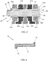
- Figure 3 shows an existing folding wing tip mechanism according to an example of the prior art.
- the mechanism includes a pin joint assembly 30.
- the pin joint assembly 30 includes a first set of lugs, first lug 41a, third lug 41c, and fifth lug 41e extending from the tip end of the wing 3 and a second set of lugs, second lug 41b, and fourth lug 41d, extending from a root end of the wing tip device 20.
- the first and fifth lugs 41a, 41e are end lugs positioned at opposing ends of the pin joint assembly 30.
- the lugs 41a-e may be aluminium lugs.
- the lugs 41a, 41b, 41c, 41d, 41e include a pin hole 31 extending therethrough, and through which a headed pin 62 is inserted.
- the headed pin 62 may be a steel pin.
- the headed pin 62 is inserted into a pin sleeve 61.
- a set of bushings are arranged between the pin sleeve 61 and each lug 41a, 42a, 43a, 43b to reduce the friction between the relative parts when the wing tip device 20 folds relative to the wing 3, and for example to protect the relatively soft aluminium of the lugs 41a-e from the steel pin 62 or pin sleeve 61.
- the bushings 63a-e may be fixed bushings, fixedly attached to each of the respective lugs 41a-e.
- the bushings 63a-e may be integral with their respective lugs 41a-e.
- the lugs 41a-e and pin 62 are made of the same material, such as steel.
- any of the bushings 63a-e may be rotatable with respect to their respective lugs 43a-e.
- the headed pin 62 has a head end 65 and a tail end 66.
- the head end 65 has a diameter larger than the pin hole 31 and headed pin 62, such that the headed pin 62 is prevented from being fully inserted into the pin hole 31.
- the tail end 66 includes a set of locking features 67 (for example locking nuts) that tighten towards the head end 65, thereby pressing the headed pin 62 against the pin sleeve 61.
- Figure 3 shows the headed pin 62 pressing against the end bushings 63a, 63e of the end wing lugs 41a, 41e, although alternatively the end lugs may be wing tip lugs.
- the end bushing 63a adjacent the tail end 66 is located on the bearing surface 71 of a substantially z-shaped bushing 70, for example as shown in cross-section in Figure 4 .
- the z-shaped bushing 70 comprises a first end flange 72 that is an inwardly extending flange, such that the flange extends towards an axis of the bushing 63a, and a second end flange 73 that is an outwardly extending flange, such that the flange extends away from the axis of the bushing 63a.
- the bearing surface 71 is defined as being between the first and second end flanges 72, 73, on which the fixed bushing 63a of the end lug 41a is positioned.
- the z-shaped end bushing 70 is clamped to a shoulder 61a of the pin sleeve 61 by a set of locking features 68. Specifically, the inwardly extending end flange 72 is clamped to the pin sleeve 61.
- the locking features 68 may comprise one or more of a locking ring 69a, tab washer 69b or thrust washer 69c.
- the z-shaped bushing 70 has a length greater than the length of the fixed bushing 63a in a direction parallel to the axis 38 of the pin 62, such that the z-shaped bushing 70 reduces the gap to the fixed bushing 63b of the adjacent lug 41b of the wing tip device 20 whilst allowing the fixed bushing 63a on its bearing surface 71 to move along the bearing surface 71.
- This third lug 41c is itself limited in its axial movement towards the head end 65, as the third lug 41c is connected to the first (end) lug 41a and fifth (end) lug 41e via the structure of the wing 3, and the axial movement of the third lug 41c is thereby restricted by the fifth lug 41e contacting the head end 65 or by the first lug 41a contacting the outwardly extending end flange 73 of the z-shaped bushing 70.
- the movement prior to the installation of the z-shaped bushing 70 may be 3 mm, 5 mm, or more so as to provide additional clearance (i.e. float) for assembling the wing 3 to the wing tip device 20.
- Installation of the z-shaped bushing 70 reduces this float to a value that is acceptable in the assembled state for actuation of the pin joint, for example, the float may be 1mm or less after assembly of the z-shaped bushing 70.
- pin joint assembly 3 There may be limited space within a structure to house the pin joint assembly 3, for example due to the aerodynamic profile of the airframe or wing structure 80 in which the mechanism may be housed.
- Figure 6 schematically shows an actuator 50 positioned between a pair of pin assemblies 30: a first pin joint assembly 30a adjacent a leading edge of the wing 3 and a second pin joint assembly 30b adjacent the trailing edge of the wing 3.
- the axes 38 of the headed pins 62 of each assembly 30a, 30b are aligned with each other to define a hinge axis of the folding assembly, for example a hinge axis 11 of the wing 3 and wing tip device 20.
- the actuator 50 fills a substantial amount of the space between the two pin joint assemblies 30a, 30b, such that the first and second pin joint assemblies 30a, 30b need to be housed close to the leading edge and trailing edge of the wing 3, respectively.
- the vertical clearance distance between the pin 62 and the wing structure 80 (e.g. the outer shell of the wing box) in a direction parallel to the axis 38 of the pin 62 varies along the length of the pin 62.
- Figure 6 shows the vertical clearance distance Y1 of the first pin joint assembly 30a and the wing structure 80 at a first end of the pin 62 adjacent the tail end 66 is smaller than the vertical clearance distance Y2 of the first pin joint assembly 30a and the wing structure 80 at a second end of the pin 62 adjacent the head end 65. This may be due to the aerodynamic profiling of the wing structure 80. This can limit the possible arrangement and orientation of the first and second pin joint assemblies 30a, 30b.
- the first pin joint assembly 30a is oriented with the tail end 66 facing towards the leading edge and the head end 65 facing towards the trailing edge. This provides additional space for the actuator 50 positioned between the first and second pin joint assemblies 30a, 30b, as the locking features 67 of the pin joint assembly 30a take up a large amount of axial space (with respect to the axial space taken by the arrangement at the head end).
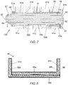
- Figure 7 shows an example of a pin joint assembly 130 according to the present invention.
- the pin assembly 130 of the present example is substantially similar to the examples of the pin assemblies 30, 30a, 30b described in relation to Figures 3 to 6 , with like numerals used to denote like parts.
- the pin joint assembly 130 may be used in a folding wing tip mechanism, as described in relation to Figure 3 , or any other type of hinge assembly, for example a pin joint assembly between a wing 3 and an aileron, slat, spoiler, flap or other control surface.
- the pin joint assembly 130 comprises a U-shaped bushing 90 having features that allow it to be positioned against a lug, for example any of the lugs 41a, 41b, 41c, 41d, 41e shown in Figure 7 , such that the U-shaped bushing 90 may be positioned on a lug 41a, 42a, 43a, 43b adjacent the head end 65 or tail end 66 of a pin 62, or anywhere in between, as will be made clear below.
- the pin joint assembly 130 may include a set of lugs, first lug 41a, third lug 41c, and fifth lug 41e extending from a first structure (for example the tip end of a wing 3) and a set of lugs, second lug 41b, and fourth lug 41d, extending from a second structure (for example the root end of a wing tip device 20).
- the first and fifth lugs 41a, 41e may be end lugs positioned at opposing ends of the pin joint assembly 130, as shown in Figure 7 .
- the lugs 41a, 41b, 41c, 41d, 41e include a pin hole 31 extending therethrough, and through which a headed pin 62 may be inserted.
- the headed pin 62 may be inserted into a pin sleeve 61.
- a set of bushings 63a, 63b, 63c, 63d, 63e, 90 may be arranged between the pin sleeve 61 and each lug 41a, 42a, 43a, 43b to reduce the friction between the relative parts when the first structure 20 folds relative to the second structure 3, with two of the bushings 63e, 90 stacked on top of each other, as will be explained below.
- the headed pin 62 has a head end 65 and a tail end 66, and a pin body 64 between the head end 65 and the tail end 66.
- the head end 65 may have a diameter larger than the pin hole 31 and headed pin 62, such that the headed pin 62 is prevented from being fully inserted into the pin hole 31.
- the head end 65 may be integral with the pin body 64, or separate to the pin body 64 such that the head end 65 may be attachable and/or detachable from the pin body 64.
- the tail end 66 may include a set of locking features 67 (for example locking nuts) that tighten towards the pin sleeve 61, thereby pressing the headed pin 62 against the pin sleeve 61.
- Figure 7 shows a pair of wing tip lugs 41b, 41d positioned between three wing lugs 41a, 41c, 41e, although any number and arrangement of lugs 41a-e may be provided.
- the U-shaped bushing 90 adjacent the head end 65 of the pin 62 comprises end flanges 92a, 92b arranged to extend outwardly from a central axis of the U-shaped bushing 90, and an outer bearing surface 95a between the flanges 92a,b.
- the U-shaped bushing 90 may be positioned adjacent the head end 65 of the pin, with the bushing 63e of the end lug 41e located between the flanges 92a,b and slidable along the outer bearing surface 95a, as shown in Figure 7 .
- the U-shaped bushing 90 may be rotatable with respect to the pin 62 via an inner bearing surface 95b (See Figure 12 A).
- U-shaped bushing 90 An example of a U-shaped bushing 90 is described in more detail in relation to Figures 8 , 9A, and 9B .
- the U-shaped bushing 90 may be a two-part bushing, for example as shown in Figure 8 .
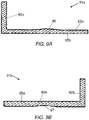
- the U-shaped bushing 90 may include a first bushing component 91a having a first body portion 93a and a first flanged portion 92a extending from the first body portion 93a.
- the first flanged portion 92a may extend substantially perpendicular from the first body portion 93a.
- the U-shaped bushing 90 may include a second bushing component 91b having a second body portion 93b and a second flanged portion 92b extending from the second body portion 93b.
- the second flanged portion 92b may extend substantially perpendicular from the second body portion 93b.
- the first body portion 93a may comprise a protrusion 96.
- the second body portion 93b may comprise a depression 97 sized to correspond to the protrusion 96.
- the protrusion 96 and depression 97 may be arranged such that the protrusion 96 is lodged in the depression 97, thereby fastening the first and second bushing components 91a,b together when the first body portion 91a overlaps the second body portion 91b. This prevents the first and second bushing components 91a, 91b from being separated easily.
- first body portion 93a may comprise a depression 97 and the second body portion 93b may comprise a protrusion 96.
- the height of the protrusion 96 and depth of the depression 97 may be partially dictated by the thickness of the first and second body portions 93a,b, for example the height of the protrusion 96 and depth of the depression 97 may be approximately half of the thickness of the first or second body portions 93a, 93b.
- the protrusion 96 and depression 97 may have a smoothly curved cross-section when viewed in a direction perpendicular to the axis of the bushing 90.
- the cross-section may be continuously circular or ovalised, and may smoothly taper towards the body portion 93a, 93b.
- the first body portion 93a may overlap the second flanged portion 92b and terminate substantially flush with an outer-most face 98 of the second flanged portion 92b, for example as shown in Figure 8 .
- This provides a join between the first and second bushing components 91a,b adjacent a side of the bushing 90, i.e. away from the inner bearing surface 95b.
- the first body portion 93a and second body portion 93b may be fastened together via an interference fit, such that the overlapping faces of the first and second body portions 93a,b may be held together by friction.
- the interference fit may be formed by freeze-fitting or shrink-fitting, wherein the relative size of one of the first or second body portions 93a,b is changed under temperature prior to assembly such that a return to room temperature forces the portions 93a,b tightly together.
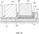
- the outer bearing surface 95a of the U-shaped bushing 90 has a length greater than a length of the bushing 63e located between the flanges 92a,b, for example as shown in Figure 10 , such that the bushing 63e may slide along the outer bearing surface 95a.
- the bushing 63e may slide by a distance defined by the difference between the length of the bearing surface 95a and the length of the bushing 63e.
- the length of the bushing 63e may correspond substantially to the contact distance of the bushing 63e with the bearing surface 95a in a direction parallel to the axis of the U-shaped bushing 90.
- Figure 10 shows an example in which the outer-most face 98 of the second flanged portion 92b is arranged adjacent the bushing 63d of the fourth lug 41d.
- the bushing 63e is slidable along the outer bearing surface 95a with respect to the outer bearing surface 95a in a direction parallel to the axis 38 of the pin 62.
- the bushing 63e of the lug 41e may be a fixed bushing fixedly attached to the lug 41e.
- the bushing 63e may be integral with the lug 41e.
- the bushing 63e may be rotatable with respect to the lug 43e.
- Each of the bushings 63a-d, 90 positioned against the pin sleeve 61 is moveable along the direction of the pin axis 38 with respect to the pin sleeve 61, such that relative movement is provided between the set of lugs 41a, 41c, 41e extending from the tip end of the wing 3 and the set of lugs 41b, 41d extending from the root end of the wing tip device 20.
- the set of lugs 41a,c,e extending from a first structure are fixedly attached to each other such that each of the lugs 41a,c,e are fixed in position relative to each of the other lugs 41a,c,e.
- the set of lugs 41b,d extending from a second structure are fixedly attached to each other such that each of the lugs 41b,d are fixed in position relative to each of the other lugs 41b,d.
- Figure 11 shows the pin joint assembly 130 in a first, rear-most, position in which the first set of lugs 41a,c,e are positioned towards the head end 65 of the pin 62, as close to the head end 65 of the pin 62 as the arrangement will allow in this example.
- a gap X1 is provided between the fixed bushing 63a of the first lug 41a and the locking features 68 that clamp against the shoulder 61a of the pin sleeve 61.
- the gap X1 is prevented from increasing in size, as the third lug 41c bears against the fourth lug 41d, which bears against the U-shaped bushing 90, which itself bears against the shoulder 61b of the pin sleeve 61.
- Gap X2 between the fifth bushing 63e of the fifth lug 41e is therefore prevented from decreasing in size.
- Figure 12 shows the pin joint assembly 130 in a second, forward-most, position in which the first set of lugs 41a,c,e are positioned towards the tail end 66 of the pin 62, such that there is no gap (i.e. gap X1 has closed up) between the fixed bushing 63a of the first lug 41a and the locking features 68 that clamp against the shoulder 61a of the pin sleeve 61, as the first lug 41a has moved forward towards the tail end 66 of the pin 62.
- gap X1 has closed up
- the gap X2 has therefore increased in size.
- the increase in size of X2 corresponds to the decrease in size of X1 with respect to the arrangement shown in Figure 11 .
- the gap X1 therefore defines an allowable amount of float between the first set of lugs 41a,c,e and the second set of lugs 41b,d.
- the float allows relative fore and aft movement between the first set of lugs 41a,c,e, the second set of lugs 41b,d, and the pin 61.
- the float may be 2 mm, 1 mm, or 0. 5mm, although the amount of float will typically depend on the size of the pin joint assembly and the particular application.
- the first set of lugs 41a,c,e, second set of lugs 41b,d, and pin sleeve 61 are moveable relative to each other, i.e. the first set of lugs 41a,c,e are movable with respect to the second set of lugs 41b,d, the first set of lugs 41a,c,e, are moveable with respect to the pin sleeve 61, and the second set of lugs 41b,d are movable with respect to the pin sleeve 61.
- Each of the bushings 63a-e, 90 of the pin joint assembly 130 is unclamped, such that they are rotatable with respect to the pin 62 and pin sleeve 61.
- the U-shaped bushing 90 reduces the amount of float without having to modify the width of the lugs, and unlike the z-shaped bushing 70 described in relation to Figure 3 to 6 , the U-shaped bushing 90 of the present invention does not need to be clamped to the pin sleeve 61. This may allow a dual slip-path between the end lug 40e of the U-shaped bushing 90 and the pin sleeve 61 (and pin 62), thereby providing a reserve slip-path in the event that one of the slip-paths is damaged or otherwise unusable.
- the U-shaped bushing 90 does not need to be clamped, it will be apparent that the U-shaped bushing 90 is suitable for positioning under any of the fixed bushings 63a-e of the lugs 41a-e, not just the fifth bushing 63e or the fifth lug 41e.
- Figure 13 schematically shows an obstruction 49 positioned between a pair of pin assemblies 130: a first pin joint assembly 130a adjacent a leading edge of the wing 3 and a second pin joint assembly 130b adjacent the trailing edge of the wing 3.
- the obstruction may be an actuator 50.
- the axes 38 of the pins 62 of each pin assembly 130a, 130b are aligned with each other to define a hinge axis of the folding assembly, for example a hinge axis 11 of the wing 3 and wing tip device 20.
- the vertical clearance distance Y1 of the first pin joint assembly 130a and the wing structure 80 at a first end of the pin 62 adjacent the tail end 66 is smaller than the vertical clearance distance Y2 of the first pin joint assembly 130a and the wing structure 80 at a second end of the pin 62 adjacent the head end 65. This may be due to the aerodynamic profiling of the wing structure 80, for example the wing structure 80 may be aerofoil shaped.
- the position of the U-shaped bushing 90 is not dictated by the position of the tail end 66 of the pin 62, in contrast to the z-shaped bushing 70, and so can be positioned adjacent the head end 65 of the pin 62, as shown in Figure 13 .
- the pin 62 described in relation to Figures 7 to 13 is shown to have a head end 65 and a tail end 66, wherein the head end 65 has a diameter larger than the pin hole 31 and headed pin 62, such that the headed pin 62 is prevented from being fully inserted into the pin hole 31.
- a headless pin 162 may be provided, in which the headless pin 162 includes a first tail end 166a with a corresponding set of locking features 167a (for example locking nuts) and a second tail end 166b with a corresponding set of locking features 167b (for example locking nuts), wherein the locking features of the first tail end 166a tighten towards the second tail end 166b and the locking features of the second tail end 166b tighten towards the first tail end 166a, thereby clamping the headed pin 162 against the pin sleeve 161.
- pin joint assemblies 130, 130a, 130b described in relation to Figures 7 to 14 are part of a folding wing tip mechanism, between a wing 2,3 and a wing tip device 20.
- a pin joint assembly 230 may be part of a flight control surface mechanism, for example between a wing 2,3 and one of a slat 12, aileron 13, spoiler 14, flap 15 or other control surface.
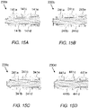
- Figure 15A shows a pin joint assembly 230a comprising a first set of lugs 141a,c,e extending from a wing 2 and a second set of lugs 141b,d extending from a slat 12.
- Figure 15B shows a pin joint assembly 230b comprising a first set of lugs 241a,c,e extending from a wing 2 and a second set of lugs 241b,d extending from an aileron 13.
- Figure 15C shows a pin joint assembly 230c comprising a first set of lugs 341a,c,e extending from a wing 2 and a second set of lugs 341b,d extending from a spoiler 14.
- Figure 15D shows a pin joint assembly 230d comprising a first set of lugs 441a,c,e extending from a wing 2 and a second set of lugs 441b,d extending from a flap 15.
- the U-shaped bushing 90 is particularly applicable in the pin joint assembly 130 shown in Figures 7 to 15 , however it will be clear that the U-shaped bushing 90 will be suitable to a wide range of pin joint assemblies.
- first and second sets may have any number of lugs, including one lug.
Landscapes
- Engineering & Computer Science (AREA)
- Mechanical Engineering (AREA)
- Aviation & Aerospace Engineering (AREA)
- General Engineering & Computer Science (AREA)
- Pivots And Pivotal Connections (AREA)
- Tires In General (AREA)
Abstract
Description
- The present invention relates to a pin joint assembly, an aircraft assembly comprising the pin joint assembly, and an aircraft comprising the aircraft assembly.
- The internal space available for components and systems within an aircraft is typically restricted, particularly in the wings where structural and aerodynamic considerations are paramount.
- Pin joints are often required within wing structures, for example to actuate control surfaces or folding wing tip mechanisms. A pin joint typically requires various bushing arrangements to reduce the friction between respective rotating surfaces, however the design of these bushing arrangements can dictate the positioning of the pin joint due to the restricted space within the aircraft structure. This can have a knock-on effect to the choice and positioning of other adjacent components within the aircraft structure.
- A first aspect of the invention provides a pin joint assembly, comprising: a first lug and a second lug; a pin extending through the first and second lugs; a U-shaped bushing between the first lug and the pin, wherein the U-shaped bushing comprises a first end flange and a second end flange that extend radially outwards and retain the U-shaped bushing to the first lug; wherein the U-shaped bushing comprises a bearing surface between the first and second end flanges on which the first lug is slidable.
- The float provided to a pin joint assembly may be relatively large for ease of assembly and then subsequently require reduction prior to operation of the pin joint. With the arrangement of the present invention, the U-shaped bushing is able to reduce the amount of float provided to a pin joint assembly, whilst allowing movement of the second bushing, as well as being positionable on any of the lugs of the pin joint.
- Preferably, the pin comprises a head end, a tail end, and a body portion between the head end and tail end, wherein the head end has a diameter greater than a diameter of the body portion.
- Preferably, the U-shaped bushing is adjacent the head end of the pin. The U-shaped bushing can be particularly advantageous in combination with a headed pin, as the U-shaped bushing can be placed anywhere along the length of the pin, including adjacent the head end.
- Preferably, the U-shaped bushing bears against the second lug. With this arrangement, relative movement between the U-shaped bushing and the second lug can be prevented.
- Preferably, the pin assembly comprises a first bushing between the first lug and the pin and/or a second bushing between the second lug and the U-shaped bushing.
- Preferably, the first bushing is a fixed bushing fixedly attached to the first lug and/or the second bushing is a fixed bushing fixedly attached to the second lug.
- Preferably, the U-shaped bushing is a two-part bushing comprising: a first bushing component having a first body portion and a first flanged portion extending from the first body portion; a second bushing component having a second body portion and a second flanged portion extending from the second body portion; wherein the first body portion is arranged to overlap the second body portion to fasten the first and second bushing components together.
- With this arrangement, the second bushing is easier to position on the bearing surface of the U-shaped bushing.
- Preferably, the first body portion overlaps the second flanged portion and terminates substantially flush with an outer-most face of the second flanged portion.
- With this arrangement, the join between the first and second bushing components is not at the inner bearing surface of the U-shaped bushing.
- Preferably, the outer-most face of the second flanged portion is arranged adjacent the head end of the pin.
- With this arrangement, the join between the first and second bushing components is not adjacent to a lug or bushing. This can be particularly advantageous when the relative rotation between U-shaped bushing and the second lug is expected to be greater than the relative rotation between the U-shaped bushing and the pin.
- Preferably, the first body portion and second body portion are fastened together via an interference fit.
- Preferably, the first body portion or second body portion comprises a protrusion, and the other of the first body portion or second body portion comprises a depression sized to correspond to the protrusion; and wherein the first and second bushing components are fastened together by lodging the protrusion into the depression.
- Preferably, the U-shaped bushing is rotatable with respect to the pin. This provides a dual-slip path, thereby providing a redundant slip path in the event that a slip path becomes damaged or otherwise unusable.
- A second aspect of the invention provides an aircraft assembly comprising the pin joint assembly of any preceding claim, a first aircraft component, and a second aircraft component, wherein the first end lug extends from one of the first or second aircraft components and the second lug extends from one of the first or second aircraft components, such that the first aircraft component is arranged to rotate relative to the second aircraft component about an axis of the pin joint assembly.
- Preferably, the first aircraft component is a main wing portion of a wing and the second aircraft component is a wing tip device.
- Preferably, the first aircraft component is a main wing portion of a wing and the second aircraft component is a flight control surface.
- Preferably, the flight control surface is one of: an aileron, a slat, a spoiler, and a flap.
- Preferably, the aircraft assembly further comprises an obstruction arranged at an obstructed end of the pin hole.
- Preferably, the obstruction is an actuator for rotating the second aircraft component relative to the first aircraft component.
- Preferably, the head end of the pin is arranged adjacent the obstruction. With this arrangement, the tail end and associated locking features may be positioned on an opposite end of the pin assembly, away from the obstruction, thereby providing additional space for the obstruction. This can be useful when the obstruction is, e.g., an actuator for actuating the first aircraft component and second aircraft component about the axis of the pin joint assembly. The obstruction may be positioned in a better position, or allow a bigger obstruction (e.g. actuator) to be installed, or even more room for maintenance.
- Preferably, the pin joint assembly is a first pin joint assembly, and the aircraft assembly further comprises a second pin joint assembly, wherein the obstruction is arranged at the obstructed end of the first pin joint assembly and at an obstructed end of the second pin joint assembly.
- Preferably, the head end of the pin of the second pin joint assembly is arranged adjacent the obstruction.
- Preferably, the first aircraft component and/or second aircraft component comprises an outer shell, and wherein a clearance distance between the pin and the outer shell in a direction parallel to an axis of the pin varies along the pin. The pin assembly can be particularly advantageous in an aircraft assembly with an outer shell (e.g. an aerodynamic shell) that causes the clearance distance between the pin assembly and outer shell to vary, as the U-shaped bushing is suitable for positioning anywhere along the pin, such that the increased stack height caused by the U-shaped bushing can be positioned where there is most clearance room.
- A third aspect of the invention provides an aircraft comprising the aircraft assembly of the second aspect.
- Embodiments of the invention will now be described with reference to the accompanying drawings, in which:
-
Figure 1 shows a perspective view of a typical fixed wing aircraft; -
Figure 2 shows a planform view of a port side wing; -
Figure 3 shows a pin joint assembly of the prior art; -
Figure 4 shows a z-shaped bushing of the prior art; -
Figure 5 shows a close-up view of the pin joint assembly ofFigure 3 ; -
Figure 6 shows an aircraft assembly including a pair of pin joint assemblies of the prior art; -
Figure 7 shows an example of a pin joint assembly of the present invention; -
Figure 8 shows a U-shaped bushing according to an example of the present invention; -
Figure 9A shows a first bushing component of the U-shaped bushing ofFigure 8 ; -
Figure 9B shows a second bushing component of the U-shaped bushing ofFigure 8 ; -
Figure 10 shows a close-up view of the pin joint assembly ofFigure 7 ; -
Figure 11 shows the pin joint assembly in a first, rear-most, position; -
Figure 12 shows the pin joint assembly in a second, forward-most, position; -
Figure 13 shows an aircraft assembly including a pair of pin joint assemblies according to the present invention; -
Figure 14 shows an example of a pin joint assembly comprising a headless pin; -
Figure 15A shows a pin joint assembly between a wing and a slat; -
Figure 15B shows a pin joint assembly between a wing and an aileron; -
Figure 15C shows a pin joint assembly between a wing and a spoiler; -
Figure 15D shows a pin joint assembly between a wing and a flap. -
Figure 1 illustrates a typical fixed wing aircraft 1. The aircraft 1 may have aport wing 2 and astarboard wing 3 that extend from afuselage 4. Eachwing engines 9. Thefuselage 4 has a nose 5 and atail 6. Thetail 6 may have horizontal and vertical stabiliser surfaces 7, 8. The aircraft 1 may be a typical jet passenger transport aircraft although the invention is applicable to a wide variety of fixed wing aircraft types, including commercial, military, passenger, cargo, jet, propeller, general aviation, etc. with any number of engines attached to the wings or fuselage. - Each
wing main wing portion 10 that is a cantilevered structure with a length extending in a span-wise direction from a wing root to a wing tip, the root being joined to theaircraft fuselage 4. Awing tip device 20 may be provided on the tip end of eachwing wings starboard wing 3 will be described in detail with reference toFigure 2 . - The
wing 3 may have a plurality of flight control surfaces. Thewing 3 may includeslats 12.Figure 2 showsslats 12 adjacent to the leading edge of thewing 3. A plurality ofslats 12 may be distributed along the span of thewing 3. Thewing 3 may include anaileron 13.Figure 2 shows anaileron 13 provided on an outboard section of the trailing edge of thewing 3. Thewing 3 may include air brakes/spoilers 14.Figure 2 shows air brakes/spoilers 14 provided across the upper surface of thewing 3 towards the trailing edge of thewing 3. Thewing 3 may include a flap 15.Figure 2 shows aninner flap 15a adjacent to the wing root, and anouter flap 15b outboard of the inner flap towards theaileron 13. - Whilst the aircraft 1 is shown with a particular quantity and configuration of control surfaces, it will be understood that the
wings - The
wing tip device 20 may be a foldingwing tip device 20 configured to rotate relative to thewing 3 about afold axis 11. Thefold axis 11 may extend from a leading edge to a trailing edge of thewing 3. The foldingwing tip device 20 may be rotated relative to thewing 3 by anactuator 50. -
Figure 3 shows an existing folding wing tip mechanism according to an example of the prior art. The mechanism includes a pinjoint assembly 30. - The pin
joint assembly 30 includes a first set of lugs,first lug 41a,third lug 41c, andfifth lug 41e extending from the tip end of thewing 3 and a second set of lugs,second lug 41b, andfourth lug 41d, extending from a root end of thewing tip device 20. The first andfifth lugs joint assembly 30. Thelugs 41a-e may be aluminium lugs. - The
lugs pin hole 31 extending therethrough, and through which a headedpin 62 is inserted. The headedpin 62 may be a steel pin. The headedpin 62 is inserted into apin sleeve 61. A set of bushings,first bushing 63a,second bushing 63b,third bushing 63c,fourth bushing 63d andfifth bushing 63e, are arranged between thepin sleeve 61 and eachlug 41a, 42a, 43a, 43b to reduce the friction between the relative parts when thewing tip device 20 folds relative to thewing 3, and for example to protect the relatively soft aluminium of thelugs 41a-e from thesteel pin 62 orpin sleeve 61. Thebushings 63a-e may be fixed bushings, fixedly attached to each of therespective lugs 41a-e. - The
bushings 63a-e may be integral with theirrespective lugs 41a-e. For example, if thelugs 41a-e andpin 62 are made of the same material, such as steel. Alternatively, any of thebushings 63a-e may be rotatable with respect to their respective lugs 43a-e. - The headed
pin 62 has ahead end 65 and atail end 66. Thehead end 65 has a diameter larger than thepin hole 31 and headedpin 62, such that the headedpin 62 is prevented from being fully inserted into thepin hole 31. Thetail end 66 includes a set of locking features 67 (for example locking nuts) that tighten towards thehead end 65, thereby pressing the headedpin 62 against thepin sleeve 61.Figure 3 shows the headedpin 62 pressing against theend bushings - The
end bushing 63a adjacent thetail end 66 is located on the bearingsurface 71 of a substantially z-shapedbushing 70, for example as shown in cross-section inFigure 4 . The z-shapedbushing 70 comprises afirst end flange 72 that is an inwardly extending flange, such that the flange extends towards an axis of thebushing 63a, and asecond end flange 73 that is an outwardly extending flange, such that the flange extends away from the axis of thebushing 63a. The bearingsurface 71 is defined as being between the first andsecond end flanges bushing 63a of theend lug 41a is positioned. - As shown in
Figure 3 , and in an expanded view shown inFigure 5 , the z-shapedend bushing 70 is clamped to ashoulder 61a of thepin sleeve 61 by a set of locking features 68. Specifically, the inwardly extendingend flange 72 is clamped to thepin sleeve 61. - The locking features 68 may comprise one or more of a
locking ring 69a,tab washer 69b or thrustwasher 69c. - The z-shaped
bushing 70 has a length greater than the length of the fixedbushing 63a in a direction parallel to theaxis 38 of thepin 62, such that the z-shapedbushing 70 reduces the gap to the fixedbushing 63b of theadjacent lug 41b of thewing tip device 20 whilst allowing the fixedbushing 63a on itsbearing surface 71 to move along the bearingsurface 71. - Consequently, the axial movement of the first set of
lugs lugs bushing 70, as the axial movement of the second set oflugs bushing 70 and in the opposite direction by thethird lug 41c. Thisthird lug 41c is itself limited in its axial movement towards thehead end 65, as thethird lug 41c is connected to the first (end)lug 41a and fifth (end)lug 41e via the structure of thewing 3, and the axial movement of thethird lug 41c is thereby restricted by thefifth lug 41e contacting thehead end 65 or by thefirst lug 41a contacting the outwardly extendingend flange 73 of the z-shapedbushing 70. - The movement prior to the installation of the z-shaped
bushing 70 may be 3 mm, 5 mm, or more so as to provide additional clearance (i.e. float) for assembling thewing 3 to thewing tip device 20. Installation of the z-shapedbushing 70 reduces this float to a value that is acceptable in the assembled state for actuation of the pin joint, for example, the float may be 1mm or less after assembly of the z-shapedbushing 70. - There may be limited space within a structure to house the pin
joint assembly 3, for example due to the aerodynamic profile of the airframe orwing structure 80 in which the mechanism may be housed. -
Figure 6 schematically shows anactuator 50 positioned between a pair of pin assemblies 30: a first pinjoint assembly 30a adjacent a leading edge of thewing 3 and a second pinjoint assembly 30b adjacent the trailing edge of thewing 3. Theaxes 38 of the headed pins 62 of eachassembly hinge axis 11 of thewing 3 andwing tip device 20. - Due to the limited space within the
wing structure 80, theactuator 50 fills a substantial amount of the space between the two pinjoint assemblies joint assemblies wing 3, respectively. - As a result, the vertical clearance distance between the
pin 62 and the wing structure 80 (e.g. the outer shell of the wing box) in a direction parallel to theaxis 38 of thepin 62 varies along the length of thepin 62. For example,Figure 6 shows the vertical clearance distance Y1 of the first pinjoint assembly 30a and thewing structure 80 at a first end of thepin 62 adjacent thetail end 66 is smaller than the vertical clearance distance Y2 of the first pinjoint assembly 30a and thewing structure 80 at a second end of thepin 62 adjacent thehead end 65. This may be due to the aerodynamic profiling of thewing structure 80. This can limit the possible arrangement and orientation of the first and second pinjoint assemblies - In
Figure 6 , the first pinjoint assembly 30a is oriented with thetail end 66 facing towards the leading edge and thehead end 65 facing towards the trailing edge. This provides additional space for theactuator 50 positioned between the first and second pinjoint assemblies joint assembly 30a take up a large amount of axial space (with respect to the axial space taken by the arrangement at the head end). - In contrast, there is limited vertical clearance towards the trailing edge of the
wing structure 80. Due to the increased stack height resulting from use of the z-shaped bushing 70 (i.e. the combined height of the z-shapedbushing 70 and the fixedbushing 63a), which is positioned against thetail end 66 of thepin 62, it is not possible to position thetail end 66 towards the trailing edge. As a result, thetail end 66 is positioned so as to face the leading edge, and thereby occupies space between the two pinjoint assemblies actuator 50. -
Figure 7 shows an example of a pinjoint assembly 130 according to the present invention. Thepin assembly 130 of the present example is substantially similar to the examples of thepin assemblies Figures 3 to 6 , with like numerals used to denote like parts. The pinjoint assembly 130 may be used in a folding wing tip mechanism, as described in relation toFigure 3 , or any other type of hinge assembly, for example a pin joint assembly between awing 3 and an aileron, slat, spoiler, flap or other control surface. - The pin
joint assembly 130 comprises aU-shaped bushing 90 having features that allow it to be positioned against a lug, for example any of thelugs Figure 7 , such that theU-shaped bushing 90 may be positioned on alug 41a, 42a, 43a, 43b adjacent thehead end 65 ortail end 66 of apin 62, or anywhere in between, as will be made clear below. - The pin
joint assembly 130 may include a set of lugs,first lug 41a,third lug 41c, andfifth lug 41e extending from a first structure (for example the tip end of a wing 3) and a set of lugs,second lug 41b, andfourth lug 41d, extending from a second structure (for example the root end of a wing tip device 20). The first andfifth lugs joint assembly 130, as shown inFigure 7 . - The
lugs pin hole 31 extending therethrough, and through which a headedpin 62 may be inserted. The headedpin 62 may be inserted into apin sleeve 61. A set ofbushings pin sleeve 61 and eachlug 41a, 42a, 43a, 43b to reduce the friction between the relative parts when thefirst structure 20 folds relative to thesecond structure 3, with two of thebushings - The headed
pin 62 has ahead end 65 and atail end 66, and apin body 64 between thehead end 65 and thetail end 66. Thehead end 65 may have a diameter larger than thepin hole 31 and headedpin 62, such that the headedpin 62 is prevented from being fully inserted into thepin hole 31. Thehead end 65 may be integral with thepin body 64, or separate to thepin body 64 such that thehead end 65 may be attachable and/or detachable from thepin body 64. - The
tail end 66 may include a set of locking features 67 (for example locking nuts) that tighten towards thepin sleeve 61, thereby pressing the headedpin 62 against thepin sleeve 61.Figure 7 shows a pair of wing tip lugs 41b, 41d positioned between threewing lugs lugs 41a-e may be provided. - The
U-shaped bushing 90 adjacent thehead end 65 of thepin 62 comprisesend flanges U-shaped bushing 90, and anouter bearing surface 95a between theflanges 92a,b. TheU-shaped bushing 90 may be positioned adjacent thehead end 65 of the pin, with thebushing 63e of theend lug 41e located between theflanges 92a,b and slidable along theouter bearing surface 95a, as shown inFigure 7 . TheU-shaped bushing 90 may be rotatable with respect to thepin 62 via aninner bearing surface 95b (SeeFigure 12 A). - An example of a
U-shaped bushing 90 is described in more detail in relation toFigures 8 ,9A, and 9B . - The
U-shaped bushing 90 may be a two-part bushing, for example as shown inFigure 8 . - The
U-shaped bushing 90 may include afirst bushing component 91a having afirst body portion 93a and a firstflanged portion 92a extending from thefirst body portion 93a. The firstflanged portion 92a may extend substantially perpendicular from thefirst body portion 93a. - The
U-shaped bushing 90 may include asecond bushing component 91b having asecond body portion 93b and a secondflanged portion 92b extending from thesecond body portion 93b. The secondflanged portion 92b may extend substantially perpendicular from thesecond body portion 93b. - The
first body portion 93a may comprise aprotrusion 96. Thesecond body portion 93b may comprise adepression 97 sized to correspond to theprotrusion 96. Theprotrusion 96 anddepression 97 may be arranged such that theprotrusion 96 is lodged in thedepression 97, thereby fastening the first andsecond bushing components 91a,b together when thefirst body portion 91a overlaps thesecond body portion 91b. This prevents the first andsecond bushing components - In an alternative example, the
first body portion 93a may comprise adepression 97 and thesecond body portion 93b may comprise aprotrusion 96. - The height of the
protrusion 96 and depth of thedepression 97 may be partially dictated by the thickness of the first andsecond body portions 93a,b, for example the height of theprotrusion 96 and depth of thedepression 97 may be approximately half of the thickness of the first orsecond body portions - The
protrusion 96 anddepression 97 may have a smoothly curved cross-section when viewed in a direction perpendicular to the axis of thebushing 90. The cross-section may be continuously circular or ovalised, and may smoothly taper towards thebody portion - The
first body portion 93a may overlap the secondflanged portion 92b and terminate substantially flush with anouter-most face 98 of the secondflanged portion 92b, for example as shown inFigure 8 . This provides a join between the first andsecond bushing components 91a,b adjacent a side of thebushing 90, i.e. away from theinner bearing surface 95b. - The
first body portion 93a andsecond body portion 93b may be fastened together via an interference fit, such that the overlapping faces of the first andsecond body portions 93a,b may be held together by friction. The interference fit may be formed by freeze-fitting or shrink-fitting, wherein the relative size of one of the first orsecond body portions 93a,b is changed under temperature prior to assembly such that a return to room temperature forces theportions 93a,b tightly together. - The
outer bearing surface 95a of theU-shaped bushing 90 has a length greater than a length of thebushing 63e located between theflanges 92a,b, for example as shown inFigure 10 , such that thebushing 63e may slide along theouter bearing surface 95a. Thebushing 63e may slide by a distance defined by the difference between the length of the bearingsurface 95a and the length of thebushing 63e. The length of thebushing 63e may correspond substantially to the contact distance of thebushing 63e with the bearingsurface 95a in a direction parallel to the axis of theU-shaped bushing 90. -
Figure 10 shows an example in which theouter-most face 98 of the secondflanged portion 92b is arranged adjacent thebushing 63d of thefourth lug 41d. In an alternative example, it may be preferable to position theouter-most face 98 of the secondflanged portion 92b adjacent thehead end 65 of thepin 62 due to the increased relative rotation expected between the first and second sets oflugs 41a-e. - The
bushing 63e is slidable along theouter bearing surface 95a with respect to theouter bearing surface 95a in a direction parallel to theaxis 38 of thepin 62. Thebushing 63e of thelug 41e may be a fixed bushing fixedly attached to thelug 41e. Thebushing 63e may be integral with thelug 41e. Alternatively, thebushing 63e may be rotatable with respect to the lug 43e. - The movement of the
bushing 63e along a direction parallel to theaxis 38 of thepin 62, with respect to theouter bearing surface 95a, is limited by theflanges 92a,b on either end of theouter bearing surface 95a. - Each of the
bushings 63a-d, 90 positioned against thepin sleeve 61 is moveable along the direction of thepin axis 38 with respect to thepin sleeve 61, such that relative movement is provided between the set oflugs wing 3 and the set oflugs wing tip device 20. - The set of
lugs 41a,c,e extending from a first structure (for example the tip end of a wing 3) are fixedly attached to each other such that each of thelugs 41a,c,e are fixed in position relative to each of theother lugs 41a,c,e. Similarly, the set oflugs 41b,d extending from a second structure (for example the root end of a wing tip device 20) are fixedly attached to each other such that each of thelugs 41b,d are fixed in position relative to each of theother lugs 41b,d. -
Figure 11 shows the pinjoint assembly 130 in a first, rear-most, position in which the first set oflugs 41a,c,e are positioned towards thehead end 65 of thepin 62, as close to thehead end 65 of thepin 62 as the arrangement will allow in this example. - In this configuration, a gap X1 is provided between the fixed
bushing 63a of thefirst lug 41a and the locking features 68 that clamp against theshoulder 61a of thepin sleeve 61. The gap X1 is prevented from increasing in size, as thethird lug 41c bears against thefourth lug 41d, which bears against theU-shaped bushing 90, which itself bears against theshoulder 61b of thepin sleeve 61. Gap X2 between thefifth bushing 63e of thefifth lug 41e is therefore prevented from decreasing in size. -
Figure 12 shows the pinjoint assembly 130 in a second, forward-most, position in which the first set oflugs 41a,c,e are positioned towards thetail end 66 of thepin 62, such that there is no gap (i.e. gap X1 has closed up) between the fixedbushing 63a of thefirst lug 41a and the locking features 68 that clamp against theshoulder 61a of thepin sleeve 61, as thefirst lug 41a has moved forward towards thetail end 66 of thepin 62. - As the
first lug 41a is connected to the third andfifth lugs first structure 3, the third andfifth lugs tail end 66 of thepin 62 with thefirst lug 41a. The gap X2 has therefore increased in size. The increase in size of X2 corresponds to the decrease in size of X1 with respect to the arrangement shown inFigure 11 . - The gap X1 therefore defines an allowable amount of float between the first set of
lugs 41a,c,e and the second set oflugs 41b,d. The float allows relative fore and aft movement between the first set oflugs 41a,c,e, the second set oflugs 41b,d, and thepin 61. The float may be 2 mm, 1 mm, or 0. 5mm, although the amount of float will typically depend on the size of the pin joint assembly and the particular application. - The first set of
lugs 41a,c,e, second set oflugs 41b,d, and pin sleeve 61 (and pin 62 attached to the pin sleeve 61) are moveable relative to each other, i.e. the first set oflugs 41a,c,e are movable with respect to the second set oflugs 41b,d, the first set oflugs 41a,c,e, are moveable with respect to thepin sleeve 61, and the second set oflugs 41b,d are movable with respect to thepin sleeve 61. Each of thebushings 63a-e, 90 of the pinjoint assembly 130 is unclamped, such that they are rotatable with respect to thepin 62 andpin sleeve 61. - The
U-shaped bushing 90 reduces the amount of float without having to modify the width of the lugs, and unlike the z-shapedbushing 70 described in relation toFigure 3 to 6 , theU-shaped bushing 90 of the present invention does not need to be clamped to thepin sleeve 61. This may allow a dual slip-path between the end lug 40e of theU-shaped bushing 90 and the pin sleeve 61 (and pin 62), thereby providing a reserve slip-path in the event that one of the slip-paths is damaged or otherwise unusable. - As the
U-shaped bushing 90 does not need to be clamped, it will be apparent that theU-shaped bushing 90 is suitable for positioning under any of the fixedbushings 63a-e of thelugs 41a-e, not just thefifth bushing 63e or thefifth lug 41e. - This allows more design freedom in the arrangement of the pin
joint assembly 130, which can have beneficial knock-on effects to other features and systems. -
Figure 13 schematically shows anobstruction 49 positioned between a pair of pin assemblies 130: a first pinjoint assembly 130a adjacent a leading edge of thewing 3 and a second pinjoint assembly 130b adjacent the trailing edge of thewing 3. The obstruction may be anactuator 50. Theaxes 38 of thepins 62 of eachpin assembly hinge axis 11 of thewing 3 andwing tip device 20. - The vertical clearance distance Y1 of the first pin
joint assembly 130a and thewing structure 80 at a first end of thepin 62 adjacent thetail end 66 is smaller than the vertical clearance distance Y2 of the first pinjoint assembly 130a and thewing structure 80 at a second end of thepin 62 adjacent thehead end 65. This may be due to the aerodynamic profiling of thewing structure 80, for example thewing structure 80 may be aerofoil shaped. - The position of the
U-shaped bushing 90 is not dictated by the position of thetail end 66 of thepin 62, in contrast to the z-shapedbushing 70, and so can be positioned adjacent thehead end 65 of thepin 62, as shown inFigure 13 . This allows the second pinjoint assembly 130b to be reversed, with respect to the arrangement shown inFigure 6 , so that thehead end 65 is positionable towards the middle of the structure. This increases the available space for fitting and positioning theactuator 50 between the pinjoint assemblies - The
pin 62 described in relation toFigures 7 to 13 is shown to have ahead end 65 and atail end 66, wherein thehead end 65 has a diameter larger than thepin hole 31 and headedpin 62, such that the headedpin 62 is prevented from being fully inserted into thepin hole 31. However, it will be appreciated that in alternative examples aheadless pin 162 may be provided, in which theheadless pin 162 includes afirst tail end 166a with a corresponding set of lockingfeatures 167a (for example locking nuts) and asecond tail end 166b with a corresponding set of lockingfeatures 167b (for example locking nuts), wherein the locking features of thefirst tail end 166a tighten towards thesecond tail end 166b and the locking features of thesecond tail end 166b tighten towards thefirst tail end 166a, thereby clamping the headedpin 162 against the pin sleeve 161. - The pin
joint assemblies Figures 7 to 14 are part of a folding wing tip mechanism, between awing wing tip device 20. In alternative examples, a pin joint assembly 230 may be part of a flight control surface mechanism, for example between awing slat 12,aileron 13,spoiler 14, flap 15 or other control surface. -
Figure 15A shows a pinjoint assembly 230a comprising a first set oflugs 141a,c,e extending from awing 2 and a second set oflugs 141b,d extending from aslat 12. -
Figure 15B shows a pinjoint assembly 230b comprising a first set oflugs 241a,c,e extending from awing 2 and a second set oflugs 241b,d extending from anaileron 13. -
Figure 15C shows a pinjoint assembly 230c comprising a first set oflugs 341a,c,e extending from awing 2 and a second set oflugs 341b,d extending from aspoiler 14. -
Figure 15D shows a pinjoint assembly 230d comprising a first set oflugs 441a,c,e extending from awing 2 and a second set oflugs 441b,d extending from a flap 15. - The
U-shaped bushing 90 is particularly applicable in the pinjoint assembly 130 shown inFigures 7 to 15 , however it will be clear that theU-shaped bushing 90 will be suitable to a wide range of pin joint assemblies. - The described examples refer to a first set of lugs comprising three lugs and a second set of lugs comprising two lugs, however it will be clear that the first and second sets may have any number of lugs, including one lug.
- Where the word 'or' appears this is to be construed to mean 'and/or' such that items referred to are not necessarily mutually exclusive and may be used in any appropriate combination.
- Although the invention has been described above with reference to one or more preferred embodiments, it will be appreciated that various changes or modifications may be made without departing from the scope of the invention as defined in the appended claims.
Claims (15)
- A pin joint assembly, comprising:a first lug and a second lug;a pin extending through the first and second lugs;a U-shaped bushing between the first lug and the pin, wherein the U-shaped bushing comprises a first end flange and a second end flange that extend radially outwards and retain the U-shaped bushing to the first lug;wherein the U-shaped bushing comprises a bearing surface between the first and second end flanges on which the first lug is slidable.
- The pin joint assembly of claim 1, wherein the pin comprises a head end, a tail end, and a body portion between the head end and tail end, wherein the head end has a diameter greater than a diameter of the body portion, and optionally wherein U-shaped bushing is adjacent the head end of the pin.
- The pin joint assembly of any preceding claim, wherein the U-shaped bushing bears against the second lug.
- The pin joint assembly of any preceding claim, comprising a first bushing between the first lug and the pin and/or a second bushing between the second lug and the U-shaped bushing, optionally wherein the first bushing is a fixed bushing fixedly attached to the first lug and/or the second bushing is a fixed bushing fixedly attached to the second lug.
- The pin joint assembly of any preceding claim, wherein the U-shaped bushing is a two-part bushing comprising:a first bushing component having a first body portion and a first flanged portion extending from the first body portion;a second bushing component having a second body portion and a second flanged portion extending from the second body portion;wherein the first body portion is arranged to overlap the second body portion to fasten the first and second bushing components together.
- The pin joint assembly of claim 5, wherein the first body portion overlaps the second flanged portion and terminates substantially flush with an outer-most face of the second flanged portion, and optionally wherein U-shaped bushing is adjacent the head end of the pin with said outer-most face of the second flanged portion arranged adjacent the head end of the pin.
- The pin joint assembly of claim 5 or 6, wherein the first body portion and second body portion are fastened together via an interference fit; and/or wherein the first body portion or second body portion comprises a protrusion, and the other of the first body portion or second body portion comprises a depression sized to correspond to the protrusion; and wherein the first and second bushing components are fastened together by lodging the protrusion into the depression.
- The pin joint assembly of any preceding claim, wherein the U-shaped bushing is rotatable with respect to the pin.
- An aircraft assembly comprising the pin joint assembly of any preceding claim, a first aircraft component, and a second aircraft component, wherein the first end lug extends from one of the first or second aircraft components and the second lug extends from the other of the first or second aircraft components, such that the first aircraft component is arranged to rotate relative to the second aircraft component about an axis of the pin joint assembly.
- The aircraft assembly of claim 9, wherein the first aircraft component is a main wing portion of a wing and the second aircraft component is a wing tip device, or wherein the first aircraft component is a main wing portion of a wing and the second aircraft component is a flight control surface, and optionally wherein the flight control surface is one of: an aileron, a slat, a spoiler, and a flap.
- The aircraft assembly of claim 9 or 10, comprising an obstruction arranged at an obstructed end of the pin hole, optionally wherein the obstruction is an actuator for rotating the second aircraft component relative to the first aircraft component.
- The aircraft assembly of claim 11 when dependent on claim 2, wherein the head end of the pin is arranged adjacent the obstruction.
- The aircraft assembly of claim 11 or 12, wherein the pin joint assembly is a first pin joint assembly, and further comprising a second pin joint assembly, wherein the obstruction is arranged at the obstructed end of the first pin joint assembly and at an obstructed end of the second pin joint assembly, and optionally wherein the head end of the pin of the second pin joint assembly is arranged adjacent the obstruction.
- The aircraft assembly of any one of claims 9 to 13, wherein the first aircraft component and/or second aircraft component comprises an outer shell, and wherein a clearance distance between the pin and the outer shell in a direction parallel to an axis of the pin varies along the pin.
- An aircraft comprising the aircraft assembly of any one of claims 9 to 14.
Applications Claiming Priority (1)
| Application Number | Priority Date | Filing Date | Title |
|---|---|---|---|
| GB2100577.2A GB2602822A (en) | 2021-01-15 | 2021-01-15 | A pin joint assembly |
Publications (2)
| Publication Number | Publication Date |
|---|---|
| EP4029773A1 true EP4029773A1 (en) | 2022-07-20 |
| EP4029773B1 EP4029773B1 (en) | 2024-03-06 |
Family
ID=74678841
Family Applications (1)
| Application Number | Title | Priority Date | Filing Date |
|---|---|---|---|
| EP22150568.8A Active EP4029773B1 (en) | 2021-01-15 | 2022-01-07 | A pin joint assembly |
Country Status (4)
| Country | Link |
|---|---|
| US (1) | US12091154B2 (en) |
| EP (1) | EP4029773B1 (en) |
| CN (1) | CN114763812A (en) |
| GB (1) | GB2602822A (en) |
Cited By (1)
| Publication number | Priority date | Publication date | Assignee | Title |
|---|---|---|---|---|
| GB2638554A (en) * | 2024-01-31 | 2025-08-27 | Skf Aerospace France Sas | Fixing assembly comprising a clevis and a tang |
Families Citing this family (1)
| Publication number | Priority date | Publication date | Assignee | Title |
|---|---|---|---|---|
| GB2643125A (en) * | 2024-07-31 | 2026-02-11 | Airbus Operations Ltd | Bush |
Citations (4)
| Publication number | Priority date | Publication date | Assignee | Title |
|---|---|---|---|---|
| US4607977A (en) * | 1985-08-05 | 1986-08-26 | Varnelis Edmund K | Pivot joint |
| EP0603840A2 (en) * | 1992-12-24 | 1994-06-29 | TECHNOMATIK MASCHINENELEMENTE GMBH & CO FERTIGUNGS KG | Pivot |
| EP2586700A2 (en) * | 2011-10-27 | 2013-05-01 | Airbus Operations Limited | Plain journal bearing |
| US20170152886A1 (en) * | 2014-08-13 | 2017-06-01 | Safran | Pivot link assembly |
Family Cites Families (5)
| Publication number | Priority date | Publication date | Assignee | Title |
|---|---|---|---|---|
| GB2509944B (en) * | 2013-01-18 | 2015-07-08 | Messier Dowty Ltd | Pin joint assembly |
| JP3198163U (en) | 2015-04-07 | 2015-06-18 | 株式会社 光陽産業 | Telescopic gate and bush |
| FR3079892B1 (en) * | 2018-04-10 | 2020-03-27 | Airbus Operations | PIVOTING CONNECTION DEVICE BETWEEN AT LEAST TWO PARTS, AIRCRAFT COMPRISING A COVER EQUIPPED WITH SAID PIVOTING CONNECTION DEVICE |
| US11820510B2 (en) * | 2019-03-26 | 2023-11-21 | Yaborã Industria Aeronautica S.A. | Quickly adjustable fail-safe link bar assemblies especially useful for connecting structural components of an aircraft |
| FR3099463B1 (en) * | 2019-08-01 | 2021-07-16 | Safran Aircraft Engines | DEVICE FOR MOUNTING AN AXLE ON A SCREED FOR AN AIRCRAFT TURBOMACHINE |
-
2021
- 2021-01-15 GB GB2100577.2A patent/GB2602822A/en not_active Withdrawn
-
2022
- 2022-01-07 EP EP22150568.8A patent/EP4029773B1/en active Active
- 2022-01-13 US US17/575,096 patent/US12091154B2/en active Active
- 2022-01-14 CN CN202210042939.9A patent/CN114763812A/en active Pending
Patent Citations (4)
| Publication number | Priority date | Publication date | Assignee | Title |
|---|---|---|---|---|
| US4607977A (en) * | 1985-08-05 | 1986-08-26 | Varnelis Edmund K | Pivot joint |
| EP0603840A2 (en) * | 1992-12-24 | 1994-06-29 | TECHNOMATIK MASCHINENELEMENTE GMBH & CO FERTIGUNGS KG | Pivot |
| EP2586700A2 (en) * | 2011-10-27 | 2013-05-01 | Airbus Operations Limited | Plain journal bearing |
| US20170152886A1 (en) * | 2014-08-13 | 2017-06-01 | Safran | Pivot link assembly |
Cited By (1)
| Publication number | Priority date | Publication date | Assignee | Title |
|---|---|---|---|---|
| GB2638554A (en) * | 2024-01-31 | 2025-08-27 | Skf Aerospace France Sas | Fixing assembly comprising a clevis and a tang |
Also Published As
| Publication number | Publication date |
|---|---|
| US20220227473A1 (en) | 2022-07-21 |
| US12091154B2 (en) | 2024-09-17 |
| EP4029773B1 (en) | 2024-03-06 |
| GB2602822A (en) | 2022-07-20 |
| CN114763812A (en) | 2022-07-19 |
| GB202100577D0 (en) | 2021-03-03 |
Similar Documents
| Publication | Publication Date | Title |
|---|---|---|
| US11242129B2 (en) | Aerofoil structure and method of assembly | |
| US11505304B2 (en) | Aircraft spoiler actuation systems and related methods | |
| US10494083B2 (en) | Aircraft flap hinge | |
| EP3263461B1 (en) | Non-circular aft nacelle cowling geometry | |
| EP4029773B1 (en) | A pin joint assembly | |
| US12043397B2 (en) | Attachment concept for a fairing on an airfoil body such as a flap or a wing of an aircraft | |
| EP2060767A2 (en) | Pivoting door thrust reverser for a turbofan gas turbine engine | |
| CN110015401B (en) | Kit of parts, airfoil structure and method for assembling an airfoil structure | |
| US12077289B2 (en) | Aircraft assembly having an integral spar-cover | |
| EP3889450B1 (en) | A barrel nut retainer | |
| US10822102B2 (en) | Adjustable length beam between cowl hinges | |
| US8567711B1 (en) | Swept-wing powered-lift aircraft | |
| EP4015850B1 (en) | An aircraft assembly | |
| EP4155214B1 (en) | A kit of parts for forming an aerofoil assembly | |
| EP1834873B1 (en) | Elastic pre-deformed fairing for aircraft and its manufacturing process | |
| US11453476B2 (en) | Structural composite airfoils with an improved leading edge, and related methods | |
| EP3112259B1 (en) | Krueger flap assembly systems and methods | |
| US20210362830A1 (en) | Structural composite airfoils with an improved leading edge, and related methods | |
| US20210362827A1 (en) | Structural composite airfoils with a single spar, and related methods | |
| US20190186184A1 (en) | Replaceable actuator tip | |
| US20260048831A1 (en) | Joint assembly | |
| US20260054846A1 (en) | Device to Secure an Engine Cowling to an Aircraft Engine | |
| EP4198293A2 (en) | Articulating slider for nacelle | |
| Smith | The structural design of an advanced short take‐off vertical landing combat aircraft—part 1 |
Legal Events
| Date | Code | Title | Description |
|---|---|---|---|
| PUAI | Public reference made under article 153(3) epc to a published international application that has entered the european phase |
Free format text: ORIGINAL CODE: 0009012 |
|
| STAA | Information on the status of an ep patent application or granted ep patent |
Free format text: STATUS: THE APPLICATION HAS BEEN PUBLISHED |
|
| AK | Designated contracting states |
Kind code of ref document: A1 Designated state(s): AL AT BE BG CH CY CZ DE DK EE ES FI FR GB GR HR HU IE IS IT LI LT LU LV MC MK MT NL NO PL PT RO RS SE SI SK SM TR |
|
| STAA | Information on the status of an ep patent application or granted ep patent |
Free format text: STATUS: REQUEST FOR EXAMINATION WAS MADE |
|
| 17P | Request for examination filed |
Effective date: 20221115 |
|
| RBV | Designated contracting states (corrected) |
Designated state(s): AL AT BE BG CH CY CZ DE DK EE ES FI FR GB GR HR HU IE IS IT LI LT LU LV MC MK MT NL NO PL PT RO RS SE SI SK SM TR |
|
| GRAP | Despatch of communication of intention to grant a patent |
Free format text: ORIGINAL CODE: EPIDOSNIGR1 |
|
| STAA | Information on the status of an ep patent application or granted ep patent |
Free format text: STATUS: GRANT OF PATENT IS INTENDED |
|
| INTG | Intention to grant announced |
Effective date: 20231004 |
|
| GRAS | Grant fee paid |
Free format text: ORIGINAL CODE: EPIDOSNIGR3 |
|
| GRAA | (expected) grant |
Free format text: ORIGINAL CODE: 0009210 |
|
| STAA | Information on the status of an ep patent application or granted ep patent |
Free format text: STATUS: THE PATENT HAS BEEN GRANTED |
|
| AK | Designated contracting states |
Kind code of ref document: B1 Designated state(s): AL AT BE BG CH CY CZ DE DK EE ES FI FR GB GR HR HU IE IS IT LI LT LU LV MC MK MT NL NO PL PT RO RS SE SI SK SM TR |
|
| REG | Reference to a national code |
Ref country code: CH Ref legal event code: EP |
|
| REG | Reference to a national code |
Ref country code: IE Ref legal event code: FG4D |
|
| REG | Reference to a national code |
Ref country code: DE Ref legal event code: R096 Ref document number: 602022002167 Country of ref document: DE |
|
| REG | Reference to a national code |
Ref country code: LT Ref legal event code: MG9D |
|
| PG25 | Lapsed in a contracting state [announced via postgrant information from national office to epo] |
Ref country code: LT Free format text: LAPSE BECAUSE OF FAILURE TO SUBMIT A TRANSLATION OF THE DESCRIPTION OR TO PAY THE FEE WITHIN THE PRESCRIBED TIME-LIMIT Effective date: 20240306 |
|
| REG | Reference to a national code |
Ref country code: NL Ref legal event code: MP Effective date: 20240306 |
|
| PG25 | Lapsed in a contracting state [announced via postgrant information from national office to epo] |
Ref country code: GR Free format text: LAPSE BECAUSE OF FAILURE TO SUBMIT A TRANSLATION OF THE DESCRIPTION OR TO PAY THE FEE WITHIN THE PRESCRIBED TIME-LIMIT Effective date: 20240607 |
|
| PG25 | Lapsed in a contracting state [announced via postgrant information from national office to epo] |
Ref country code: HR Free format text: LAPSE BECAUSE OF FAILURE TO SUBMIT A TRANSLATION OF THE DESCRIPTION OR TO PAY THE FEE WITHIN THE PRESCRIBED TIME-LIMIT Effective date: 20240306 Ref country code: RS Free format text: LAPSE BECAUSE OF FAILURE TO SUBMIT A TRANSLATION OF THE DESCRIPTION OR TO PAY THE FEE WITHIN THE PRESCRIBED TIME-LIMIT Effective date: 20240606 |
|
| PG25 | Lapsed in a contracting state [announced via postgrant information from national office to epo] |
Ref country code: ES Free format text: LAPSE BECAUSE OF FAILURE TO SUBMIT A TRANSLATION OF THE DESCRIPTION OR TO PAY THE FEE WITHIN THE PRESCRIBED TIME-LIMIT Effective date: 20240306 |
|
| PG25 | Lapsed in a contracting state [announced via postgrant information from national office to epo] |
Ref country code: RS Free format text: LAPSE BECAUSE OF FAILURE TO SUBMIT A TRANSLATION OF THE DESCRIPTION OR TO PAY THE FEE WITHIN THE PRESCRIBED TIME-LIMIT Effective date: 20240606 Ref country code: NO Free format text: LAPSE BECAUSE OF FAILURE TO SUBMIT A TRANSLATION OF THE DESCRIPTION OR TO PAY THE FEE WITHIN THE PRESCRIBED TIME-LIMIT Effective date: 20240606 Ref country code: LT Free format text: LAPSE BECAUSE OF FAILURE TO SUBMIT A TRANSLATION OF THE DESCRIPTION OR TO PAY THE FEE WITHIN THE PRESCRIBED TIME-LIMIT Effective date: 20240306 Ref country code: HR Free format text: LAPSE BECAUSE OF FAILURE TO SUBMIT A TRANSLATION OF THE DESCRIPTION OR TO PAY THE FEE WITHIN THE PRESCRIBED TIME-LIMIT Effective date: 20240306 Ref country code: GR Free format text: LAPSE BECAUSE OF FAILURE TO SUBMIT A TRANSLATION OF THE DESCRIPTION OR TO PAY THE FEE WITHIN THE PRESCRIBED TIME-LIMIT Effective date: 20240607 Ref country code: FI Free format text: LAPSE BECAUSE OF FAILURE TO SUBMIT A TRANSLATION OF THE DESCRIPTION OR TO PAY THE FEE WITHIN THE PRESCRIBED TIME-LIMIT Effective date: 20240306 Ref country code: ES Free format text: LAPSE BECAUSE OF FAILURE TO SUBMIT A TRANSLATION OF THE DESCRIPTION OR TO PAY THE FEE WITHIN THE PRESCRIBED TIME-LIMIT Effective date: 20240306 Ref country code: BG Free format text: LAPSE BECAUSE OF FAILURE TO SUBMIT A TRANSLATION OF THE DESCRIPTION OR TO PAY THE FEE WITHIN THE PRESCRIBED TIME-LIMIT Effective date: 20240306 |
|
| REG | Reference to a national code |
Ref country code: AT Ref legal event code: MK05 Ref document number: 1663248 Country of ref document: AT Kind code of ref document: T Effective date: 20240306 |
|
| PG25 | Lapsed in a contracting state [announced via postgrant information from national office to epo] |
Ref country code: SE Free format text: LAPSE BECAUSE OF FAILURE TO SUBMIT A TRANSLATION OF THE DESCRIPTION OR TO PAY THE FEE WITHIN THE PRESCRIBED TIME-LIMIT Effective date: 20240306 Ref country code: LV Free format text: LAPSE BECAUSE OF FAILURE TO SUBMIT A TRANSLATION OF THE DESCRIPTION OR TO PAY THE FEE WITHIN THE PRESCRIBED TIME-LIMIT Effective date: 20240306 |
|
| PG25 | Lapsed in a contracting state [announced via postgrant information from national office to epo] |
Ref country code: NL Free format text: LAPSE BECAUSE OF FAILURE TO SUBMIT A TRANSLATION OF THE DESCRIPTION OR TO PAY THE FEE WITHIN THE PRESCRIBED TIME-LIMIT Effective date: 20240306 |
|
| PG25 | Lapsed in a contracting state [announced via postgrant information from national office to epo] |
Ref country code: NL Free format text: LAPSE BECAUSE OF FAILURE TO SUBMIT A TRANSLATION OF THE DESCRIPTION OR TO PAY THE FEE WITHIN THE PRESCRIBED TIME-LIMIT Effective date: 20240306 |
|
| PG25 | Lapsed in a contracting state [announced via postgrant information from national office to epo] |
Ref country code: IS Free format text: LAPSE BECAUSE OF FAILURE TO SUBMIT A TRANSLATION OF THE DESCRIPTION OR TO PAY THE FEE WITHIN THE PRESCRIBED TIME-LIMIT Effective date: 20240706 |
|
| PG25 | Lapsed in a contracting state [announced via postgrant information from national office to epo] |
Ref country code: PT Free format text: LAPSE BECAUSE OF FAILURE TO SUBMIT A TRANSLATION OF THE DESCRIPTION OR TO PAY THE FEE WITHIN THE PRESCRIBED TIME-LIMIT Effective date: 20240708 Ref country code: SM Free format text: LAPSE BECAUSE OF FAILURE TO SUBMIT A TRANSLATION OF THE DESCRIPTION OR TO PAY THE FEE WITHIN THE PRESCRIBED TIME-LIMIT Effective date: 20240306 |
|
| PG25 | Lapsed in a contracting state [announced via postgrant information from national office to epo] |
Ref country code: CZ Free format text: LAPSE BECAUSE OF FAILURE TO SUBMIT A TRANSLATION OF THE DESCRIPTION OR TO PAY THE FEE WITHIN THE PRESCRIBED TIME-LIMIT Effective date: 20240306 Ref country code: EE Free format text: LAPSE BECAUSE OF FAILURE TO SUBMIT A TRANSLATION OF THE DESCRIPTION OR TO PAY THE FEE WITHIN THE PRESCRIBED TIME-LIMIT Effective date: 20240306 |
|
| PG25 | Lapsed in a contracting state [announced via postgrant information from national office to epo] |
Ref country code: AT Free format text: LAPSE BECAUSE OF FAILURE TO SUBMIT A TRANSLATION OF THE DESCRIPTION OR TO PAY THE FEE WITHIN THE PRESCRIBED TIME-LIMIT Effective date: 20240306 |
|
| PG25 | Lapsed in a contracting state [announced via postgrant information from national office to epo] |
Ref country code: PL Free format text: LAPSE BECAUSE OF FAILURE TO SUBMIT A TRANSLATION OF THE DESCRIPTION OR TO PAY THE FEE WITHIN THE PRESCRIBED TIME-LIMIT Effective date: 20240306 |
|
| PG25 | Lapsed in a contracting state [announced via postgrant information from national office to epo] |
Ref country code: SK Free format text: LAPSE BECAUSE OF FAILURE TO SUBMIT A TRANSLATION OF THE DESCRIPTION OR TO PAY THE FEE WITHIN THE PRESCRIBED TIME-LIMIT Effective date: 20240306 |
|
| PG25 | Lapsed in a contracting state [announced via postgrant information from national office to epo] |
Ref country code: SM Free format text: LAPSE BECAUSE OF FAILURE TO SUBMIT A TRANSLATION OF THE DESCRIPTION OR TO PAY THE FEE WITHIN THE PRESCRIBED TIME-LIMIT Effective date: 20240306 Ref country code: SK Free format text: LAPSE BECAUSE OF FAILURE TO SUBMIT A TRANSLATION OF THE DESCRIPTION OR TO PAY THE FEE WITHIN THE PRESCRIBED TIME-LIMIT Effective date: 20240306 Ref country code: RO Free format text: LAPSE BECAUSE OF FAILURE TO SUBMIT A TRANSLATION OF THE DESCRIPTION OR TO PAY THE FEE WITHIN THE PRESCRIBED TIME-LIMIT Effective date: 20240306 Ref country code: PT Free format text: LAPSE BECAUSE OF FAILURE TO SUBMIT A TRANSLATION OF THE DESCRIPTION OR TO PAY THE FEE WITHIN THE PRESCRIBED TIME-LIMIT Effective date: 20240708 Ref country code: PL Free format text: LAPSE BECAUSE OF FAILURE TO SUBMIT A TRANSLATION OF THE DESCRIPTION OR TO PAY THE FEE WITHIN THE PRESCRIBED TIME-LIMIT Effective date: 20240306 Ref country code: IS Free format text: LAPSE BECAUSE OF FAILURE TO SUBMIT A TRANSLATION OF THE DESCRIPTION OR TO PAY THE FEE WITHIN THE PRESCRIBED TIME-LIMIT Effective date: 20240706 Ref country code: EE Free format text: LAPSE BECAUSE OF FAILURE TO SUBMIT A TRANSLATION OF THE DESCRIPTION OR TO PAY THE FEE WITHIN THE PRESCRIBED TIME-LIMIT Effective date: 20240306 Ref country code: CZ Free format text: LAPSE BECAUSE OF FAILURE TO SUBMIT A TRANSLATION OF THE DESCRIPTION OR TO PAY THE FEE WITHIN THE PRESCRIBED TIME-LIMIT Effective date: 20240306 Ref country code: AT Free format text: LAPSE BECAUSE OF FAILURE TO SUBMIT A TRANSLATION OF THE DESCRIPTION OR TO PAY THE FEE WITHIN THE PRESCRIBED TIME-LIMIT Effective date: 20240306 |
|
| PG25 | Lapsed in a contracting state [announced via postgrant information from national office to epo] |
Ref country code: IT Free format text: LAPSE BECAUSE OF FAILURE TO SUBMIT A TRANSLATION OF THE DESCRIPTION OR TO PAY THE FEE WITHIN THE PRESCRIBED TIME-LIMIT Effective date: 20240306 |
|
| REG | Reference to a national code |
Ref country code: DE Ref legal event code: R097 Ref document number: 602022002167 Country of ref document: DE |
|
| PG25 | Lapsed in a contracting state [announced via postgrant information from national office to epo] |
Ref country code: IT Free format text: LAPSE BECAUSE OF FAILURE TO SUBMIT A TRANSLATION OF THE DESCRIPTION OR TO PAY THE FEE WITHIN THE PRESCRIBED TIME-LIMIT Effective date: 20240306 |
|
| PLBE | No opposition filed within time limit |
Free format text: ORIGINAL CODE: 0009261 |
|
| STAA | Information on the status of an ep patent application or granted ep patent |
Free format text: STATUS: NO OPPOSITION FILED WITHIN TIME LIMIT |
|
| PG25 | Lapsed in a contracting state [announced via postgrant information from national office to epo] |
Ref country code: DK Free format text: LAPSE BECAUSE OF FAILURE TO SUBMIT A TRANSLATION OF THE DESCRIPTION OR TO PAY THE FEE WITHIN THE PRESCRIBED TIME-LIMIT Effective date: 20240306 |
|
| PG25 | Lapsed in a contracting state [announced via postgrant information from national office to epo] |
Ref country code: DK Free format text: LAPSE BECAUSE OF FAILURE TO SUBMIT A TRANSLATION OF THE DESCRIPTION OR TO PAY THE FEE WITHIN THE PRESCRIBED TIME-LIMIT Effective date: 20240306 |
|
| 26N | No opposition filed |
Effective date: 20241209 |
|
| PG25 | Lapsed in a contracting state [announced via postgrant information from national office to epo] |
Ref country code: SI Free format text: LAPSE BECAUSE OF FAILURE TO SUBMIT A TRANSLATION OF THE DESCRIPTION OR TO PAY THE FEE WITHIN THE PRESCRIBED TIME-LIMIT Effective date: 20240306 |
|
| REG | Reference to a national code |
Ref country code: CH Ref legal event code: PL |
|
| PG25 | Lapsed in a contracting state [announced via postgrant information from national office to epo] |
Ref country code: LU Free format text: LAPSE BECAUSE OF NON-PAYMENT OF DUE FEES Effective date: 20250107 Ref country code: MC Free format text: LAPSE BECAUSE OF FAILURE TO SUBMIT A TRANSLATION OF THE DESCRIPTION OR TO PAY THE FEE WITHIN THE PRESCRIBED TIME-LIMIT Effective date: 20240306 |
|
| PG25 | Lapsed in a contracting state [announced via postgrant information from national office to epo] |
Ref country code: BE Free format text: LAPSE BECAUSE OF NON-PAYMENT OF DUE FEES Effective date: 20250131 |
|
| PG25 | Lapsed in a contracting state [announced via postgrant information from national office to epo] |
Ref country code: CH Free format text: LAPSE BECAUSE OF NON-PAYMENT OF DUE FEES Effective date: 20250131 |
|
| REG | Reference to a national code |
Ref country code: BE Ref legal event code: MM Effective date: 20250131 |
|
| PG25 | Lapsed in a contracting state [announced via postgrant information from national office to epo] |
Ref country code: IE Free format text: LAPSE BECAUSE OF NON-PAYMENT OF DUE FEES Effective date: 20250107 |
|
| PGFP | Annual fee paid to national office [announced via postgrant information from national office to epo] |
Ref country code: GB Payment date: 20260123 Year of fee payment: 5 |
|
| PGFP | Annual fee paid to national office [announced via postgrant information from national office to epo] |
Ref country code: DE Payment date: 20260121 Year of fee payment: 5 |
|
| PGFP | Annual fee paid to national office [announced via postgrant information from national office to epo] |
Ref country code: FR Payment date: 20260123 Year of fee payment: 5 |