EP4029708A1 - Control system of the conditioning of a cab of a vehicle - Google Patents
Control system of the conditioning of a cab of a vehicle Download PDFInfo
- Publication number
- EP4029708A1 EP4029708A1 EP22151634.7A EP22151634A EP4029708A1 EP 4029708 A1 EP4029708 A1 EP 4029708A1 EP 22151634 A EP22151634 A EP 22151634A EP 4029708 A1 EP4029708 A1 EP 4029708A1
- Authority
- EP
- European Patent Office
- Prior art keywords
- vehicle
- conditioning
- mechanical knob
- cabin
- parts
- Prior art date
- Legal status (The legal status is an assumption and is not a legal conclusion. Google has not performed a legal analysis and makes no representation as to the accuracy of the status listed.)
- Granted
Links
Images
Classifications
-
- B—PERFORMING OPERATIONS; TRANSPORTING
- B60—VEHICLES IN GENERAL
- B60H—ARRANGEMENTS OF HEATING, COOLING, VENTILATING OR OTHER AIR-TREATING DEVICES SPECIALLY ADAPTED FOR PASSENGER OR GOODS SPACES OF VEHICLES
- B60H1/00—Heating, cooling or ventilating devices
- B60H1/00642—Control systems or circuits; Control members or indication devices for heating, cooling or ventilating devices
- B60H1/0065—Control members, e.g. levers or knobs
-
- B—PERFORMING OPERATIONS; TRANSPORTING
- B60—VEHICLES IN GENERAL
- B60K—ARRANGEMENT OR MOUNTING OF PROPULSION UNITS OR OF TRANSMISSIONS IN VEHICLES; ARRANGEMENT OR MOUNTING OF PLURAL DIVERSE PRIME-MOVERS IN VEHICLES; AUXILIARY DRIVES FOR VEHICLES; INSTRUMENTATION OR DASHBOARDS FOR VEHICLES; ARRANGEMENTS IN CONNECTION WITH COOLING, AIR INTAKE, GAS EXHAUST OR FUEL SUPPLY OF PROPULSION UNITS IN VEHICLES
- B60K37/00—Dashboards
- B60K37/20—Dashboard panels
-
- B—PERFORMING OPERATIONS; TRANSPORTING
- B60—VEHICLES IN GENERAL
- B60H—ARRANGEMENTS OF HEATING, COOLING, VENTILATING OR OTHER AIR-TREATING DEVICES SPECIALLY ADAPTED FOR PASSENGER OR GOODS SPACES OF VEHICLES
- B60H1/00—Heating, cooling or ventilating devices
- B60H1/00642—Control systems or circuits; Control members or indication devices for heating, cooling or ventilating devices
- B60H1/00985—Control systems or circuits characterised by display or indicating devices, e.g. voice simulators
-
- B—PERFORMING OPERATIONS; TRANSPORTING
- B60—VEHICLES IN GENERAL
- B60K—ARRANGEMENT OR MOUNTING OF PROPULSION UNITS OR OF TRANSMISSIONS IN VEHICLES; ARRANGEMENT OR MOUNTING OF PLURAL DIVERSE PRIME-MOVERS IN VEHICLES; AUXILIARY DRIVES FOR VEHICLES; INSTRUMENTATION OR DASHBOARDS FOR VEHICLES; ARRANGEMENTS IN CONNECTION WITH COOLING, AIR INTAKE, GAS EXHAUST OR FUEL SUPPLY OF PROPULSION UNITS IN VEHICLES
- B60K35/00—Instruments specially adapted for vehicles; Arrangement of instruments in or on vehicles
- B60K35/10—Input arrangements, i.e. from user to vehicle, associated with vehicle functions or specially adapted therefor
-
- B—PERFORMING OPERATIONS; TRANSPORTING
- B60—VEHICLES IN GENERAL
- B60K—ARRANGEMENT OR MOUNTING OF PROPULSION UNITS OR OF TRANSMISSIONS IN VEHICLES; ARRANGEMENT OR MOUNTING OF PLURAL DIVERSE PRIME-MOVERS IN VEHICLES; AUXILIARY DRIVES FOR VEHICLES; INSTRUMENTATION OR DASHBOARDS FOR VEHICLES; ARRANGEMENTS IN CONNECTION WITH COOLING, AIR INTAKE, GAS EXHAUST OR FUEL SUPPLY OF PROPULSION UNITS IN VEHICLES
- B60K35/00—Instruments specially adapted for vehicles; Arrangement of instruments in or on vehicles
- B60K35/20—Output arrangements, i.e. from vehicle to user, associated with vehicle functions or specially adapted therefor
- B60K35/21—Output arrangements, i.e. from vehicle to user, associated with vehicle functions or specially adapted therefor using visual output, e.g. blinking lights or matrix displays
- B60K35/212—Output arrangements, i.e. from vehicle to user, associated with vehicle functions or specially adapted therefor using visual output, e.g. blinking lights or matrix displays displaying on manual operation elements, e.g. on a knob
-
- B—PERFORMING OPERATIONS; TRANSPORTING
- B60—VEHICLES IN GENERAL
- B60K—ARRANGEMENT OR MOUNTING OF PROPULSION UNITS OR OF TRANSMISSIONS IN VEHICLES; ARRANGEMENT OR MOUNTING OF PLURAL DIVERSE PRIME-MOVERS IN VEHICLES; AUXILIARY DRIVES FOR VEHICLES; INSTRUMENTATION OR DASHBOARDS FOR VEHICLES; ARRANGEMENTS IN CONNECTION WITH COOLING, AIR INTAKE, GAS EXHAUST OR FUEL SUPPLY OF PROPULSION UNITS IN VEHICLES
- B60K35/00—Instruments specially adapted for vehicles; Arrangement of instruments in or on vehicles
- B60K35/80—Arrangements for controlling instruments
-
- B—PERFORMING OPERATIONS; TRANSPORTING
- B60—VEHICLES IN GENERAL
- B60K—ARRANGEMENT OR MOUNTING OF PROPULSION UNITS OR OF TRANSMISSIONS IN VEHICLES; ARRANGEMENT OR MOUNTING OF PLURAL DIVERSE PRIME-MOVERS IN VEHICLES; AUXILIARY DRIVES FOR VEHICLES; INSTRUMENTATION OR DASHBOARDS FOR VEHICLES; ARRANGEMENTS IN CONNECTION WITH COOLING, AIR INTAKE, GAS EXHAUST OR FUEL SUPPLY OF PROPULSION UNITS IN VEHICLES
- B60K2360/00—Indexing scheme associated with groups B60K35/00 or B60K37/00 relating to details of instruments or dashboards
- B60K2360/126—Rotatable input devices for instruments
-
- B—PERFORMING OPERATIONS; TRANSPORTING
- B60—VEHICLES IN GENERAL
- B60K—ARRANGEMENT OR MOUNTING OF PROPULSION UNITS OR OF TRANSMISSIONS IN VEHICLES; ARRANGEMENT OR MOUNTING OF PLURAL DIVERSE PRIME-MOVERS IN VEHICLES; AUXILIARY DRIVES FOR VEHICLES; INSTRUMENTATION OR DASHBOARDS FOR VEHICLES; ARRANGEMENTS IN CONNECTION WITH COOLING, AIR INTAKE, GAS EXHAUST OR FUEL SUPPLY OF PROPULSION UNITS IN VEHICLES
- B60K2360/00—Indexing scheme associated with groups B60K35/00 or B60K37/00 relating to details of instruments or dashboards
- B60K2360/139—Clusters of instrument input devices
Definitions
- the invention relates to a system for controlling a conditioning system of a vehicle cabin.
- One of the aspect that requires a particularly careful designing is the control of the conditioning system. Indeed, in some environmental conditions, for example in winter or summer, a strong conditioning of the cabin is necessary in order to ensure a correct comfort.
- control system which are normally obtained on the dashboard of the vehicle and comprise rotating knobs, displays and buttons configured to transmit a control signal to a control unit of the conditioning systems.
- the object of the invention is to fulfil the needs discussed above in an optimized and economic fashion.
- number 1 generally indicates a system for controlling the conditioning of a cabin of a heavy vehicle.
- the control system 1 can be integrated in a dashboard 2 inside the cabin (which is not shown herein) of the heavy vehicle or in any inner portion of the cabin deemed to be comfortable for the use of the driver of the vehicle.
- control system 1 comprises one single pair of mechanical knob regulators 3, 4 next to one another and spaced apart from one another at a distance that is approximately equal to the one of the mechanical knob regulators 3, 4. Said distance preferably is circa 50 mm.
- each mechanical knob regulator 3, 4 comprises a central portion 3b and an annular portion 3a, 4a, which can rotate around the central portion 3b, 4b.
- the central portion 3b, 4b has a cylindrical shape and, hence, extends from the dashboard 2 towards the inside of the cabin and defines a circular lateral surface centred on a respective axis A, B, around which the respective annular portion 3a, 4a can slide in a circumferential manner.
- the two central portions 3b, 4b are arranged so that the axes A, B intersect a same straight line C.
- each central portion 3b, 4b is divided into at least a pair of portions configured to be selectively pressed by the driver of the vehicle like buttons in order to select different functions, as discussed below.
- each central portion 3b, 4b is divided into three portions 3b', 3b", 3b''', 4b', 4b", 4b'' vertically arranged on top of one another, i.e. placed on one another in a direction perpendicular to the straight line C.
- each annular portion further defines at least one indicator portion 3a', 4a' configured to be integral to the annular portion 3a, 4a so as to indicate an angular position thereof relative to the central portion 3b, 4b.
- said indicator portion 3a', 4a' can comprise a projection, which is manufactured as one single piece together with the annular portion 3a, 4a and radially extends from the latter on the opposite side relative to the central portion 3b, 4b.
- each annular portion 3a, 4a comprises two projections, which are diametrically opposite one another.
- the control system 1 further comprises a plurality of graphic signs 5, 6, 7, 8 made on the dashboard 2 and/or on the mechanical knob regulators 3, 4 and representing different functions that can be adjusted by means of the mechanical knob regulators 3, 4.
- each mechanical knob regulator 3, 4 defines, on the respective central portion 3b, 4b, a graphic sign 5, 6 representing, in a shaped manner, the specific shape of the cabin of the vehicle equipped with the control system 1.
- the graphic sign 5, 6 is divided into three portions representing as many areas/functions that can be activated by having the driver press the relative portion 3b', 3b", 3b"', 4b', 4b ⁇ , 4b′′′.
- each annular portion 3a, 4a basically defining a circular crown that can have different colours or thicknesses in order to represent temperatures and/or intensities of the signal that can be controlled through the rotation of the annular portion 3a, 4a.
- a first mechanical knob regulator 3 is configured to control the temperature value inside the cabin of the vehicle and a second mechanical knob regulator 4 is configured to adjust the intensity of the air flow supplied into the cabin of the vehicle.
- the portions 4b', 4b", 4b''' of the second mechanical knob regulator 4 can be selected in combination with one another and enable the activation of the ventilation in the cabin portion represented by the graphic sign 6, i.e., with reference to figure 1 , the lower, central and upper portion of the cabin.
- the portions 3b′, 3b ⁇ , 3b′′′ of the first mechanical knob regulator 3 can only be selected alternatively to one another and enable the activation of the special thermal functions in the cabin portion represented by the graphic sign 5.
- these special thermal functions can comprise:
- one or more of the portions 5b', 5b", 5b''' of the mechanical knob regulator 5 can be selected in order to control the conditioning of the cabin when the vehicle is parked, thus subjecting the cabin to the so-called park cooling or park heating functions.
- the rotation of the annular portions 3a, 4a or the pressing of one of the portions 3b', 3b", 3b"', 4b′, 4b ⁇ , 4b′′′ generates an electric signal that can be acquired by a control unit of the cabin conditioning system, which comprises electronic means configured to control the flow rate, the direction and the temperature of the air conditioning flow accordingly.
- control system 1 The embodiment of the control system 1 described above works as follows.
- drivers can press one of the portions 3b′, 3b ⁇ , 3b′′′ in order to select a special thermal function, while the vehicle is running or is parked, which will automatically adjust the flow and the temperature according to the specific information stored in the control unit of the conditioning system.
- the conditioning system can be controlled in an extremely versatile manner in a compact space and with mechanical control systems, such as buttons or knobs, which, hence, are easy and economic to be manufactured.
- the conditioning system is extremely compact and can be installed in small spaces, besides being capable of replacing already existing systems.
- control system according to the invention can be subjected to changes and variants, which, though, do not go beyond the scope of protection set forth in the appended claims.
- first and second mechanical knob regulator can be different.
- shape of the indicator portions and their number can be different.
- the graphic signs change according to the shape of the cabin of the vehicle where the system is installed.
Landscapes
- Engineering & Computer Science (AREA)
- Mechanical Engineering (AREA)
- Chemical & Material Sciences (AREA)
- Combustion & Propulsion (AREA)
- Transportation (AREA)
- Physics & Mathematics (AREA)
- Thermal Sciences (AREA)
- Air-Conditioning For Vehicles (AREA)
- Vehicle Body Suspensions (AREA)
- Component Parts Of Construction Machinery (AREA)
Abstract
Description
- This Patent Application claims priority from
Italian Patent Application No. 102021000000596 filed on January 14, 2021 - The invention relates to a system for controlling a conditioning system of a vehicle cabin.
- Heavy vehicles, such as trucks, are normally provided with a cabin, which must be designed so as to allow drivers to fulfil travel tasks, which include driving on a road as well as refreshment breaks, with utmost comfort.
- One of the aspect that requires a particularly careful designing is the control of the conditioning system. Indeed, in some environmental conditions, for example in winter or summer, a strong conditioning of the cabin is necessary in order to ensure a correct comfort.
- To this aim, control system are known, which are normally obtained on the dashboard of the vehicle and comprise rotating knobs, displays and buttons configured to transmit a control signal to a control unit of the conditioning systems.
- These systems currently are extremely bulky in order to define a wide range of control elements or, if they are compact, clearly are scarcely versatile. Moreover, merely digital controls, for example from a screen, are very expensive and need a re-designing of the spaces of the dashboard.
- Therefore, systems for controlling the conditioning system of a vehicle cabin are needed, which are compact and versatile.
- The object of the invention is to fulfil the needs discussed above in an optimized and economic fashion.
- The aforesaid object is reached by a conditioning system controlling system and by a vehicle according to the appended independent claims.
- Further preferred embodiments of the invention are described in the dependent claims or in the claims connected to the aforesaid independent claims.
- The invention will be best understood upon perusal of the following detailed description of a preferred embodiment, which is provided by way of non-limiting example, with reference to the accompanying drawing,
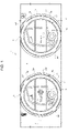
figure 1 , schematically showing a system according to the invention. - In
figure 1 , number 1 generally indicates a system for controlling the conditioning of a cabin of a heavy vehicle. - The control system 1 can be integrated in a dashboard 2 inside the cabin (which is not shown herein) of the heavy vehicle or in any inner portion of the cabin deemed to be comfortable for the use of the driver of the vehicle.
- In particular, according to the invention, the control system 1 comprises one single pair of
mechanical knob regulators mechanical knob regulators - In particular, each
mechanical knob regulator central portion 3b and anannular portion central portion central portion annular portion - Preferably, the two
central portions - More in detail, each
central portion - More in detail, in the embodiment described herein, each
central portion portions 3b', 3b", 3b''', 4b', 4b", 4b''' vertically arranged on top of one another, i.e. placed on one another in a direction perpendicular to the straight line C. - Preferably, each annular portion further defines at least one
indicator portion 3a', 4a' configured to be integral to theannular portion central portion - More in detail, said
indicator portion 3a', 4a' can comprise a projection, which is manufactured as one single piece together with theannular portion central portion - In the embodiment described herein, each
annular portion - The control system 1 further comprises a plurality of graphic signs 5, 6, 7, 8 made on the dashboard 2 and/or on the
mechanical knob regulators mechanical knob regulators - In particular, each
mechanical knob regulator central portion - As a consequence of the description above, the graphic sign 5, 6 is divided into three portions representing as many areas/functions that can be activated by having the driver press the
relative portion 3b', 3b", 3b"', 4b', 4bʺ, 4b‴. - More in detail, further graphic signs 7, 8 are provided around each
annular portion annular portion - More in detail, a first
mechanical knob regulator 3 is configured to control the temperature value inside the cabin of the vehicle and a secondmechanical knob regulator 4 is configured to adjust the intensity of the air flow supplied into the cabin of the vehicle. - Preferably, the
portions 4b', 4b", 4b''' of the secondmechanical knob regulator 4 can be selected in combination with one another and enable the activation of the ventilation in the cabin portion represented by the graphic sign 6, i.e., with reference tofigure 1 , the lower, central and upper portion of the cabin. - Preferably, the
portions 3b′, 3bʺ, 3b‴ of the firstmechanical knob regulator 3 can only be selected alternatively to one another and enable the activation of the special thermal functions in the cabin portion represented by the graphic sign 5. In particular and by way of example, these special thermal functions can comprise: - A. A maximum heating of the lower part of the cabin;
- B. A maximum cooling of the central part of the cabin; or
- C. A maximum heating of the upper part of the cabin.
- In particular and by way of example, the aforesaid functions A, B and C can be carried out as shown in the table below:
Function Temperature Speed Distribution Compressor Recirculation A Maximum maximum Cabin lower part On On B Minimum maximum Cabin central part On On C Maximum maximum Cabin upper part On Off - Optionally, if they are pressed when the vehicle is parked, one or more of the portions 5b', 5b", 5b''' of the mechanical knob regulator 5 can be selected in order to control the conditioning of the cabin when the vehicle is parked, thus subjecting the cabin to the so-called park cooling or park heating functions.
- Clearly, the rotation of the
annular portions portions 3b', 3b", 3b"', 4b′, 4bʺ, 4b‴ generates an electric signal that can be acquired by a control unit of the cabin conditioning system, which comprises electronic means configured to control the flow rate, the direction and the temperature of the air conditioning flow accordingly. - The embodiment of the control system 1 described above works as follows.
- Users can manage the area and the flow rate of the air flow through the second
mechanical knob regulator 4 as well as manage the temperature of said air flow through the firstmechanical knob regulator 3. In particular, the intensity of the flow/temperature is adjusted through the rotation of theannular portions central portion indicator portion 3a', 4a' on the respective graphic sign 7, 8. - Alternatively, drivers can press one of the
portions 3b′, 3bʺ, 3b‴ in order to select a special thermal function, while the vehicle is running or is parked, which will automatically adjust the flow and the temperature according to the specific information stored in the control unit of the conditioning system. - Owing to the above, the advantages of a control system according to the invention are evident.
- Thanks to the system disclosed herein, the conditioning system can be controlled in an extremely versatile manner in a compact space and with mechanical control systems, such as buttons or knobs, which, hence, are easy and economic to be manufactured.
- More in detail, thanks to the specific shape of the vehicle represented on the central portion, it is extremely simple to understand which portion is controlled by the respective knob.
- Moreover, thanks to the selection of special thermal functions, both when the vehicle is running and when it is parked, specific conditioning cycles can be activated with one single button, without having to carry out a manual adjustment.
- Since the system comprises only two knobs, the conditioning system is extremely compact and can be installed in small spaces, besides being capable of replacing already existing systems.
- Finally, the control system according to the invention can be subjected to changes and variants, which, though, do not go beyond the scope of protection set forth in the appended claims.
- Clearly, the shape of the first and second mechanical knob regulator can be different. Similarly, the shape of the indicator portions and their number can be different.
- As already mentioned above, the graphic signs change according to the shape of the cabin of the vehicle where the system is installed.
Claims (11)
- Control system (1) for managing the conditioning of a vehicle cabin, said control system (1) comprising a first and a second mechanical knob regulator (3, 4), each of said first and second mechanical knob regulator (3, 4) comprising a central portion (3b, 4b) and an annular portion (3a, 4a) rotating around said central portion (3b, 4b), each of said central portions (3b, 4b) being divided into several parts (3b′, 3bʺ, 3b‴, 4′, 4bʺ, 4b‴) selectable by the user, each annular portion (3a, 4a) including at least one indicator portion (3a' , 4a') configured to indicate the relative angular position between said annular portion (3a, 4a) and the respective central portion (3b, 4b),
said parts (3b′, 3bʺ, 3b‴, 4b′, 4bʺ, 4b‴) and said annular portion (3a, 4a) being connected to a control unit of a conditioning system of said vehicle. - System according to claim 1, wherein said indicating portion (3a', 4a') comprises a projection extending radially from said annular indicating portion (3a, 4a) on the opposite side of said central portion (3b, 4b) .
- System according to claim 1 or 2, in which said parts (3b', 3b", 3b"', 4b', 4b", 4b"') are made on top of each other along a direction perpendicular to an axis (C) joining the centers of rotation (A, B) of said annular portions (3a, 4a).
- A system according to one of the preceding claims, comprising first graphic signs (5, 6) made on said central portion (3b, 4b), said first graphic signs (5, 6) representing in a stylized way said cab of said vehicle.
- System according to one of the preceding claims, comprising second graphic signs (7, 8) made around said annular portions (3a, 4a), said second graphic signs (7, 8) representing in a stylized way the intensity of a signal adjustable by means of said annular portions (3a, 4a).
- System according to one of the preceding claims in which said first mechanical knob regulator (3) is configured to control the temperature value of an air flow that can be supplied by said conditioning system and in which said second mechanical knob regulator (4) is configured to control the flow rate value of an air flow that can be supplied by said conditioning system.
- System according to claim 6, wherein the parts (4b′, 4bʺ, 4b‴) of said second mechanical knob regulator (4) are configured to select the area of said air flow, said parts (4b′, 4bʺ, 4b‴) being selectable individually or in combination.
- System according to claim 6 or 7, in which the parts (3b′, 3bʺ, 3b‴) of said first mechanical knob regulator (3) are selectable only individually and are configured to activate special thermal functions of conditioning of the cabin of said vehicle, said special thermal functions being stored in said conditioning system.
- System according to claim 8, wherein the parts (3b′, 3bʺ, 3b‴) of said first mechanical knob regulator (3) are selectable when said vehicle is parked to select further special thermal conditioning functions of the cabin of said vehicle, said further special thermal functions being memorized in said conditioning system.
- System according to one of the preceding claims, in which said system (1) comprises only said first and second mechanical knob regulators (3, 4), said first and second mechanical knob regulators (3, 4) being placed side by side with a distance of about 50 mm.
- A vehicle comprising a cabin provided with a control system according to the preceding claims.
Applications Claiming Priority (1)
| Application Number | Priority Date | Filing Date | Title |
|---|---|---|---|
| IT102021000000596A IT202100000596A1 (en) | 2021-01-14 | 2021-01-14 | VEHICLE CAB AIR CONDITIONING CONTROL SYSTEM |
Publications (3)
| Publication Number | Publication Date |
|---|---|
| EP4029708A1 true EP4029708A1 (en) | 2022-07-20 |
| EP4029708C0 EP4029708C0 (en) | 2024-06-19 |
| EP4029708B1 EP4029708B1 (en) | 2024-06-19 |
Family
ID=75252704
Family Applications (1)
| Application Number | Title | Priority Date | Filing Date |
|---|---|---|---|
| EP22151634.7A Active EP4029708B1 (en) | 2021-01-14 | 2022-01-14 | Control system of the air conditioning of a cabin of a vehicle |
Country Status (2)
| Country | Link |
|---|---|
| EP (1) | EP4029708B1 (en) |
| IT (1) | IT202100000596A1 (en) |
Citations (4)
| Publication number | Priority date | Publication date | Assignee | Title |
|---|---|---|---|---|
| FR2773117A1 (en) * | 1997-12-31 | 1999-07-02 | Valeo Climatisation | Vehicle control board typically for heating/ventilation |
| JP2006264636A (en) * | 2005-03-25 | 2006-10-05 | Denso Corp | Air conditioner control unit |
| US20090084220A1 (en) * | 2007-09-28 | 2009-04-02 | U-Shin Ltd | Dial Control Device |
| CN106114126B (en) * | 2016-06-27 | 2018-07-17 | 北京新能源汽车股份有限公司 | Control method of air conditioning system of electric automobile |
-
2021
- 2021-01-14 IT IT102021000000596A patent/IT202100000596A1/en unknown
-
2022
- 2022-01-14 EP EP22151634.7A patent/EP4029708B1/en active Active
Patent Citations (4)
| Publication number | Priority date | Publication date | Assignee | Title |
|---|---|---|---|---|
| FR2773117A1 (en) * | 1997-12-31 | 1999-07-02 | Valeo Climatisation | Vehicle control board typically for heating/ventilation |
| JP2006264636A (en) * | 2005-03-25 | 2006-10-05 | Denso Corp | Air conditioner control unit |
| US20090084220A1 (en) * | 2007-09-28 | 2009-04-02 | U-Shin Ltd | Dial Control Device |
| CN106114126B (en) * | 2016-06-27 | 2018-07-17 | 北京新能源汽车股份有限公司 | Control method of air conditioning system of electric automobile |
Also Published As
| Publication number | Publication date |
|---|---|
| IT202100000596A1 (en) | 2022-07-14 |
| EP4029708C0 (en) | 2024-06-19 |
| EP4029708B1 (en) | 2024-06-19 |
Similar Documents
| Publication | Publication Date | Title |
|---|---|---|
| US5555502A (en) | Display and control apparatus for the electronic systems of a motor vehicle | |
| US5821935A (en) | Graphical user interface with electronic feature access | |
| EP2662263B1 (en) | A steering device for a vehicle | |
| EP2165865B1 (en) | An automotive user interface for a ventilation or airconditioning system of a road vehicle | |
| US5916288A (en) | Multi-functional control switch arrangement | |
| EP1291205B1 (en) | Setting system for an air-conditioner in a vehicle | |
| CN111572620B (en) | Steering control device, method of operating its indicator lighting system and motor vehicle | |
| DE102015121805B4 (en) | Arrangement for a heating, ventilation and air conditioning system and vehicle | |
| JP7421493B2 (en) | User interface and method and system for controlling air conditioner | |
| US20020002432A1 (en) | Automobile multifunctional display and control device method | |
| US7614682B1 (en) | Steering assembly HVAC system | |
| US20090098815A1 (en) | User specific climate control system | |
| KR101520324B1 (en) | Controller for air conditioner in vehicles | |
| US20130274968A1 (en) | Eco-climate control system | |
| EP4029708A1 (en) | Control system of the conditioning of a cab of a vehicle | |
| US6823685B2 (en) | Vehicle air conditioning device | |
| US7405651B2 (en) | Operating element for a heating and air conditioning system | |
| JP2011526227A (en) | Vehicle heating and / or air conditioner with automatic heating and air conditioning control function | |
| US6758265B2 (en) | Temperature control strategy for a rear control system | |
| CN104442274B (en) | Car air conditioner state displaying control method and device | |
| KR20160105590A (en) | Air conditioning system for automotive vehicles | |
| US20040130535A1 (en) | Panel comprising elements for controlling the air conditioning in a vehicle | |
| US11052728B2 (en) | Air inlet apparatus and method for operating an air inlet | |
| DE4443026B4 (en) | Heating and / or air conditioning for motor vehicles | |
| JPH0329607B2 (en) |
Legal Events
| Date | Code | Title | Description |
|---|---|---|---|
| PUAI | Public reference made under article 153(3) epc to a published international application that has entered the european phase |
Free format text: ORIGINAL CODE: 0009012 |
|
| STAA | Information on the status of an ep patent application or granted ep patent |
Free format text: STATUS: THE APPLICATION HAS BEEN PUBLISHED |
|
| AK | Designated contracting states |
Kind code of ref document: A1 Designated state(s): AL AT BE BG CH CY CZ DE DK EE ES FI FR GB GR HR HU IE IS IT LI LT LU LV MC MK MT NL NO PL PT RO RS SE SI SK SM TR |
|
| STAA | Information on the status of an ep patent application or granted ep patent |
Free format text: STATUS: REQUEST FOR EXAMINATION WAS MADE |
|
| 17P | Request for examination filed |
Effective date: 20230117 |
|
| RBV | Designated contracting states (corrected) |
Designated state(s): AL AT BE BG CH CY CZ DE DK EE ES FI FR GB GR HR HU IE IS IT LI LT LU LV MC MK MT NL NO PL PT RO RS SE SI SK SM TR |
|
| STAA | Information on the status of an ep patent application or granted ep patent |
Free format text: STATUS: EXAMINATION IS IN PROGRESS |
|
| 17Q | First examination report despatched |
Effective date: 20230601 |
|
| GRAP | Despatch of communication of intention to grant a patent |
Free format text: ORIGINAL CODE: EPIDOSNIGR1 |
|
| STAA | Information on the status of an ep patent application or granted ep patent |
Free format text: STATUS: GRANT OF PATENT IS INTENDED |
|
| INTG | Intention to grant announced |
Effective date: 20240109 |
|
| GRAS | Grant fee paid |
Free format text: ORIGINAL CODE: EPIDOSNIGR3 |
|
| GRAA | (expected) grant |
Free format text: ORIGINAL CODE: 0009210 |
|
| STAA | Information on the status of an ep patent application or granted ep patent |
Free format text: STATUS: THE PATENT HAS BEEN GRANTED |
|
| AK | Designated contracting states |
Kind code of ref document: B1 Designated state(s): AL AT BE BG CH CY CZ DE DK EE ES FI FR GB GR HR HU IE IS IT LI LT LU LV MC MK MT NL NO PL PT RO RS SE SI SK SM TR |
|
| REG | Reference to a national code |
Ref country code: GB Ref legal event code: FG4D |
|
| REG | Reference to a national code |
Ref country code: CH Ref legal event code: EP |
|
| REG | Reference to a national code |
Ref country code: DE Ref legal event code: R096 Ref document number: 602022003965 Country of ref document: DE |
|
| U01 | Request for unitary effect filed |
Effective date: 20240619 |
|
| U07 | Unitary effect registered |
Designated state(s): AT BE BG DE DK EE FI FR IT LT LU LV MT NL PT SE SI Effective date: 20240626 |
|
| PG25 | Lapsed in a contracting state [announced via postgrant information from national office to epo] |
Ref country code: HR Free format text: LAPSE BECAUSE OF FAILURE TO SUBMIT A TRANSLATION OF THE DESCRIPTION OR TO PAY THE FEE WITHIN THE PRESCRIBED TIME-LIMIT Effective date: 20240619 |
|
| PG25 | Lapsed in a contracting state [announced via postgrant information from national office to epo] |
Ref country code: GR Free format text: LAPSE BECAUSE OF FAILURE TO SUBMIT A TRANSLATION OF THE DESCRIPTION OR TO PAY THE FEE WITHIN THE PRESCRIBED TIME-LIMIT Effective date: 20240920 |
|
| PG25 | Lapsed in a contracting state [announced via postgrant information from national office to epo] |
Ref country code: NO Free format text: LAPSE BECAUSE OF FAILURE TO SUBMIT A TRANSLATION OF THE DESCRIPTION OR TO PAY THE FEE WITHIN THE PRESCRIBED TIME-LIMIT Effective date: 20240919 Ref country code: HR Free format text: LAPSE BECAUSE OF FAILURE TO SUBMIT A TRANSLATION OF THE DESCRIPTION OR TO PAY THE FEE WITHIN THE PRESCRIBED TIME-LIMIT Effective date: 20240619 Ref country code: GR Free format text: LAPSE BECAUSE OF FAILURE TO SUBMIT A TRANSLATION OF THE DESCRIPTION OR TO PAY THE FEE WITHIN THE PRESCRIBED TIME-LIMIT Effective date: 20240920 Ref country code: RS Free format text: LAPSE BECAUSE OF FAILURE TO SUBMIT A TRANSLATION OF THE DESCRIPTION OR TO PAY THE FEE WITHIN THE PRESCRIBED TIME-LIMIT Effective date: 20240919 |
|
| PG25 | Lapsed in a contracting state [announced via postgrant information from national office to epo] |
Ref country code: PL Free format text: LAPSE BECAUSE OF FAILURE TO SUBMIT A TRANSLATION OF THE DESCRIPTION OR TO PAY THE FEE WITHIN THE PRESCRIBED TIME-LIMIT Effective date: 20240619 |
|
| PG25 | Lapsed in a contracting state [announced via postgrant information from national office to epo] |
Ref country code: IS Free format text: LAPSE BECAUSE OF FAILURE TO SUBMIT A TRANSLATION OF THE DESCRIPTION OR TO PAY THE FEE WITHIN THE PRESCRIBED TIME-LIMIT Effective date: 20241019 |
|
| PG25 | Lapsed in a contracting state [announced via postgrant information from national office to epo] |
Ref country code: CZ Free format text: LAPSE BECAUSE OF FAILURE TO SUBMIT A TRANSLATION OF THE DESCRIPTION OR TO PAY THE FEE WITHIN THE PRESCRIBED TIME-LIMIT Effective date: 20240619 |
|
| PG25 | Lapsed in a contracting state [announced via postgrant information from national office to epo] |
Ref country code: RO Free format text: LAPSE BECAUSE OF FAILURE TO SUBMIT A TRANSLATION OF THE DESCRIPTION OR TO PAY THE FEE WITHIN THE PRESCRIBED TIME-LIMIT Effective date: 20240619 Ref country code: SK Free format text: LAPSE BECAUSE OF FAILURE TO SUBMIT A TRANSLATION OF THE DESCRIPTION OR TO PAY THE FEE WITHIN THE PRESCRIBED TIME-LIMIT Effective date: 20240619 |
|
| PG25 | Lapsed in a contracting state [announced via postgrant information from national office to epo] |
Ref country code: SM Free format text: LAPSE BECAUSE OF FAILURE TO SUBMIT A TRANSLATION OF THE DESCRIPTION OR TO PAY THE FEE WITHIN THE PRESCRIBED TIME-LIMIT Effective date: 20240619 Ref country code: ES Free format text: LAPSE BECAUSE OF FAILURE TO SUBMIT A TRANSLATION OF THE DESCRIPTION OR TO PAY THE FEE WITHIN THE PRESCRIBED TIME-LIMIT Effective date: 20240619 |
|
| PG25 | Lapsed in a contracting state [announced via postgrant information from national office to epo] |
Ref country code: SM Free format text: LAPSE BECAUSE OF FAILURE TO SUBMIT A TRANSLATION OF THE DESCRIPTION OR TO PAY THE FEE WITHIN THE PRESCRIBED TIME-LIMIT Effective date: 20240619 Ref country code: SK Free format text: LAPSE BECAUSE OF FAILURE TO SUBMIT A TRANSLATION OF THE DESCRIPTION OR TO PAY THE FEE WITHIN THE PRESCRIBED TIME-LIMIT Effective date: 20240619 Ref country code: RO Free format text: LAPSE BECAUSE OF FAILURE TO SUBMIT A TRANSLATION OF THE DESCRIPTION OR TO PAY THE FEE WITHIN THE PRESCRIBED TIME-LIMIT Effective date: 20240619 Ref country code: PL Free format text: LAPSE BECAUSE OF FAILURE TO SUBMIT A TRANSLATION OF THE DESCRIPTION OR TO PAY THE FEE WITHIN THE PRESCRIBED TIME-LIMIT Effective date: 20240619 Ref country code: IS Free format text: LAPSE BECAUSE OF FAILURE TO SUBMIT A TRANSLATION OF THE DESCRIPTION OR TO PAY THE FEE WITHIN THE PRESCRIBED TIME-LIMIT Effective date: 20241019 Ref country code: ES Free format text: LAPSE BECAUSE OF FAILURE TO SUBMIT A TRANSLATION OF THE DESCRIPTION OR TO PAY THE FEE WITHIN THE PRESCRIBED TIME-LIMIT Effective date: 20240619 Ref country code: CZ Free format text: LAPSE BECAUSE OF FAILURE TO SUBMIT A TRANSLATION OF THE DESCRIPTION OR TO PAY THE FEE WITHIN THE PRESCRIBED TIME-LIMIT Effective date: 20240619 |
|
| U20 | Renewal fee for the european patent with unitary effect paid |
Year of fee payment: 4 Effective date: 20250120 |
|
| PLBE | No opposition filed within time limit |
Free format text: ORIGINAL CODE: 0009261 |
|
| STAA | Information on the status of an ep patent application or granted ep patent |
Free format text: STATUS: NO OPPOSITION FILED WITHIN TIME LIMIT |
|
| 26N | No opposition filed |
Effective date: 20250320 |
|
| REG | Reference to a national code |
Ref country code: CH Ref legal event code: PL |
|
| PG25 | Lapsed in a contracting state [announced via postgrant information from national office to epo] |
Ref country code: MC Free format text: LAPSE BECAUSE OF FAILURE TO SUBMIT A TRANSLATION OF THE DESCRIPTION OR TO PAY THE FEE WITHIN THE PRESCRIBED TIME-LIMIT Effective date: 20240619 |
|
| PG25 | Lapsed in a contracting state [announced via postgrant information from national office to epo] |
Ref country code: CH Free format text: LAPSE BECAUSE OF NON-PAYMENT OF DUE FEES Effective date: 20250131 |
|
| U20 | Renewal fee for the european patent with unitary effect paid |
Year of fee payment: 5 Effective date: 20251211 |
|
| PG25 | Lapsed in a contracting state [announced via postgrant information from national office to epo] |
Ref country code: IE Free format text: LAPSE BECAUSE OF NON-PAYMENT OF DUE FEES Effective date: 20250114 |