EP4029488B1 - A system for providing information to pedestrians - Google Patents
A system for providing information to pedestrians Download PDFInfo
- Publication number
- EP4029488B1 EP4029488B1 EP22150894.8A EP22150894A EP4029488B1 EP 4029488 B1 EP4029488 B1 EP 4029488B1 EP 22150894 A EP22150894 A EP 22150894A EP 4029488 B1 EP4029488 B1 EP 4029488B1
- Authority
- EP
- European Patent Office
- Prior art keywords
- transmitter
- protocol
- receiver
- information signal
- bluetooth
- Prior art date
- Legal status (The legal status is an assumption and is not a legal conclusion. Google has not performed a legal analysis and makes no representation as to the accuracy of the status listed.)
- Active
Links
Images

Classifications
-
- A—HUMAN NECESSITIES
- A61—MEDICAL OR VETERINARY SCIENCE; HYGIENE
- A61H—PHYSICAL THERAPY APPARATUS, e.g. DEVICES FOR LOCATING OR STIMULATING REFLEX POINTS IN THE BODY; ARTIFICIAL RESPIRATION; MASSAGE; BATHING DEVICES FOR SPECIAL THERAPEUTIC OR HYGIENIC PURPOSES OR SPECIFIC PARTS OF THE BODY
- A61H3/00—Appliances for aiding patients or disabled persons to walk about
- A61H3/06—Walking aids for blind persons
- A61H3/061—Walking aids for blind persons with electronic detecting or guiding means
-
- A—HUMAN NECESSITIES
- A61—MEDICAL OR VETERINARY SCIENCE; HYGIENE
- A61H—PHYSICAL THERAPY APPARATUS, e.g. DEVICES FOR LOCATING OR STIMULATING REFLEX POINTS IN THE BODY; ARTIFICIAL RESPIRATION; MASSAGE; BATHING DEVICES FOR SPECIAL THERAPEUTIC OR HYGIENIC PURPOSES OR SPECIFIC PARTS OF THE BODY
- A61H3/00—Appliances for aiding patients or disabled persons to walk about
- A61H3/06—Walking aids for blind persons
- A61H3/066—Installations on the floor, e.g. special surfaces, to guide blind persons
-
- G—PHYSICS
- G08—SIGNALLING
- G08G—TRAFFIC CONTROL SYSTEMS
- G08G1/00—Traffic control systems for road vehicles
- G08G1/005—Traffic control systems for road vehicles including pedestrian guidance indicator
-
- G—PHYSICS
- G09—EDUCATION; CRYPTOGRAPHY; DISPLAY; ADVERTISING; SEALS
- G09B—EDUCATIONAL OR DEMONSTRATION APPLIANCES; APPLIANCES FOR TEACHING, OR COMMUNICATING WITH, THE BLIND, DEAF OR MUTE; MODELS; PLANETARIA; GLOBES; MAPS; DIAGRAMS
- G09B21/00—Teaching, or communicating with, the blind, deaf or mute
- G09B21/001—Teaching or communicating with blind persons
- G09B21/006—Teaching or communicating with blind persons using audible presentation of the information
-
- A—HUMAN NECESSITIES
- A61—MEDICAL OR VETERINARY SCIENCE; HYGIENE
- A61H—PHYSICAL THERAPY APPARATUS, e.g. DEVICES FOR LOCATING OR STIMULATING REFLEX POINTS IN THE BODY; ARTIFICIAL RESPIRATION; MASSAGE; BATHING DEVICES FOR SPECIAL THERAPEUTIC OR HYGIENIC PURPOSES OR SPECIFIC PARTS OF THE BODY
- A61H3/00—Appliances for aiding patients or disabled persons to walk about
- A61H3/06—Walking aids for blind persons
- A61H3/061—Walking aids for blind persons with electronic detecting or guiding means
- A61H2003/063—Walking aids for blind persons with electronic detecting or guiding means with tactile perception
-
- A—HUMAN NECESSITIES
- A61—MEDICAL OR VETERINARY SCIENCE; HYGIENE
- A61H—PHYSICAL THERAPY APPARATUS, e.g. DEVICES FOR LOCATING OR STIMULATING REFLEX POINTS IN THE BODY; ARTIFICIAL RESPIRATION; MASSAGE; BATHING DEVICES FOR SPECIAL THERAPEUTIC OR HYGIENIC PURPOSES OR SPECIFIC PARTS OF THE BODY
- A61H2201/00—Characteristics of apparatus not provided for in the preceding codes
- A61H2201/50—Control means thereof
- A61H2201/5007—Control means thereof computer controlled
-
- A—HUMAN NECESSITIES
- A61—MEDICAL OR VETERINARY SCIENCE; HYGIENE
- A61H—PHYSICAL THERAPY APPARATUS, e.g. DEVICES FOR LOCATING OR STIMULATING REFLEX POINTS IN THE BODY; ARTIFICIAL RESPIRATION; MASSAGE; BATHING DEVICES FOR SPECIAL THERAPEUTIC OR HYGIENIC PURPOSES OR SPECIFIC PARTS OF THE BODY
- A61H2201/00—Characteristics of apparatus not provided for in the preceding codes
- A61H2201/50—Control means thereof
- A61H2201/5007—Control means thereof computer controlled
- A61H2201/501—Control means thereof computer controlled connected to external computer devices or networks
- A61H2201/5012—Control means thereof computer controlled connected to external computer devices or networks using the internet
-
- A—HUMAN NECESSITIES
- A61—MEDICAL OR VETERINARY SCIENCE; HYGIENE
- A61H—PHYSICAL THERAPY APPARATUS, e.g. DEVICES FOR LOCATING OR STIMULATING REFLEX POINTS IN THE BODY; ARTIFICIAL RESPIRATION; MASSAGE; BATHING DEVICES FOR SPECIAL THERAPEUTIC OR HYGIENIC PURPOSES OR SPECIFIC PARTS OF THE BODY
- A61H2201/00—Characteristics of apparatus not provided for in the preceding codes
- A61H2201/50—Control means thereof
- A61H2201/5023—Interfaces to the user
- A61H2201/5038—Interfaces to the user freely programmable by the user
-
- A—HUMAN NECESSITIES
- A61—MEDICAL OR VETERINARY SCIENCE; HYGIENE
- A61H—PHYSICAL THERAPY APPARATUS, e.g. DEVICES FOR LOCATING OR STIMULATING REFLEX POINTS IN THE BODY; ARTIFICIAL RESPIRATION; MASSAGE; BATHING DEVICES FOR SPECIAL THERAPEUTIC OR HYGIENIC PURPOSES OR SPECIFIC PARTS OF THE BODY
- A61H2201/00—Characteristics of apparatus not provided for in the preceding codes
- A61H2201/50—Control means thereof
- A61H2201/5023—Interfaces to the user
- A61H2201/5048—Audio interfaces, e.g. voice or music controlled
-
- A—HUMAN NECESSITIES
- A61—MEDICAL OR VETERINARY SCIENCE; HYGIENE
- A61H—PHYSICAL THERAPY APPARATUS, e.g. DEVICES FOR LOCATING OR STIMULATING REFLEX POINTS IN THE BODY; ARTIFICIAL RESPIRATION; MASSAGE; BATHING DEVICES FOR SPECIAL THERAPEUTIC OR HYGIENIC PURPOSES OR SPECIFIC PARTS OF THE BODY
- A61H2201/00—Characteristics of apparatus not provided for in the preceding codes
- A61H2201/50—Control means thereof
- A61H2201/5058—Sensors or detectors
-
- A—HUMAN NECESSITIES
- A61—MEDICAL OR VETERINARY SCIENCE; HYGIENE
- A61H—PHYSICAL THERAPY APPARATUS, e.g. DEVICES FOR LOCATING OR STIMULATING REFLEX POINTS IN THE BODY; ARTIFICIAL RESPIRATION; MASSAGE; BATHING DEVICES FOR SPECIAL THERAPEUTIC OR HYGIENIC PURPOSES OR SPECIFIC PARTS OF THE BODY
- A61H2201/00—Characteristics of apparatus not provided for in the preceding codes
- A61H2201/50—Control means thereof
- A61H2201/5058—Sensors or detectors
- A61H2201/5064—Position sensors
-
- A—HUMAN NECESSITIES
- A61—MEDICAL OR VETERINARY SCIENCE; HYGIENE
- A61H—PHYSICAL THERAPY APPARATUS, e.g. DEVICES FOR LOCATING OR STIMULATING REFLEX POINTS IN THE BODY; ARTIFICIAL RESPIRATION; MASSAGE; BATHING DEVICES FOR SPECIAL THERAPEUTIC OR HYGIENIC PURPOSES OR SPECIFIC PARTS OF THE BODY
- A61H2201/00—Characteristics of apparatus not provided for in the preceding codes
- A61H2201/50—Control means thereof
- A61H2201/5058—Sensors or detectors
- A61H2201/5069—Angle sensors
-
- A—HUMAN NECESSITIES
- A61—MEDICAL OR VETERINARY SCIENCE; HYGIENE
- A61H—PHYSICAL THERAPY APPARATUS, e.g. DEVICES FOR LOCATING OR STIMULATING REFLEX POINTS IN THE BODY; ARTIFICIAL RESPIRATION; MASSAGE; BATHING DEVICES FOR SPECIAL THERAPEUTIC OR HYGIENIC PURPOSES OR SPECIFIC PARTS OF THE BODY
- A61H2201/00—Characteristics of apparatus not provided for in the preceding codes
- A61H2201/50—Control means thereof
- A61H2201/5058—Sensors or detectors
- A61H2201/5084—Acceleration sensors
-
- A—HUMAN NECESSITIES
- A61—MEDICAL OR VETERINARY SCIENCE; HYGIENE
- A61H—PHYSICAL THERAPY APPARATUS, e.g. DEVICES FOR LOCATING OR STIMULATING REFLEX POINTS IN THE BODY; ARTIFICIAL RESPIRATION; MASSAGE; BATHING DEVICES FOR SPECIAL THERAPEUTIC OR HYGIENIC PURPOSES OR SPECIFIC PARTS OF THE BODY
- A61H2201/00—Characteristics of apparatus not provided for in the preceding codes
- A61H2201/50—Control means thereof
- A61H2201/5058—Sensors or detectors
- A61H2201/5092—Optical sensor
-
- A—HUMAN NECESSITIES
- A61—MEDICAL OR VETERINARY SCIENCE; HYGIENE
- A61H—PHYSICAL THERAPY APPARATUS, e.g. DEVICES FOR LOCATING OR STIMULATING REFLEX POINTS IN THE BODY; ARTIFICIAL RESPIRATION; MASSAGE; BATHING DEVICES FOR SPECIAL THERAPEUTIC OR HYGIENIC PURPOSES OR SPECIFIC PARTS OF THE BODY
- A61H2201/00—Characteristics of apparatus not provided for in the preceding codes
- A61H2201/50—Control means thereof
- A61H2201/5097—Control means thereof wireless
-
- G—PHYSICS
- G08—SIGNALLING
- G08G—TRAFFIC CONTROL SYSTEMS
- G08G1/00—Traffic control systems for road vehicles
- G08G1/01—Detecting movement of traffic to be counted or controlled
- G08G1/02—Detecting movement of traffic to be counted or controlled using treadles built into the road
Definitions
- the present invention relates to a system for providing information to pedestrians. More particularly, but not exclusively, the present invention relates to a system for providing information to pedestrians comprising a plurality of protrusions, a wireless transmitter and a wireless receiver, the transmitter being adapted to transmit an information signal to the receiver and the receiver being adapted to generate an alert signal in response thereto.
- Systems for providing information to pedestrians are known. Such systems typically find application at crossings and the like where they are of particular use to pedestrians who are blind or who have limited vision. As the pedestrian approaches the crossing they are provided with useful information by the system.
- PCT/GB2019/051944 discloses an example of such a system.
- the system comprises a plurality of protrusions attached to the pavement surface. These provide a tactile indication to the pedestrian that they are approaching the crossing.
- Arranged between the protrusions is a plurality of passive RFID tags.
- the pedestrian carries a cane.
- Arranged within the cane is a transmitter. As the pedestrian approaches the crossing the signal transmitted by the transmitter excites the passive RFID tag which sends a return signal back to the cane.
- a receiver within the cane receives the return signal and converts it into speech.
- a problem with such a system is that one requires a large number of passive RFID tags to effectively cover the crossing area.
- the present invention seeks to overcome the problems of the prior art.
- the present invention provides a system for providing information to pedestrians comprising a plurality of protrusions
- the system according to the invention employs at least one active transmitter. Only a small number of such transmitters, possibly only one such transmitter, are therefore required. This substantially reduces installation cost, increases ease of installation and increases the reliability of the system.
- the wireless transmitter is arranged between at least two of the plurality of protrusions.
- the system further comprises a substrate, the plurality of protrusions and the transmitter being arranged on the substrate.
- the substrate is a portion of a pavement.
- the substrate is a portion of a railway platform.
- the protrusions are connected together by connecting arms.
- the system further comprises a resin layer covering the protrusions and transmitter.
- the wireless receiver is a mobile phone.
- the alert comprises at least one of a sound, speech, an image or video.
- the transmitter is configured such that the information signal can be changed remotely.
- the transmitter is configured such that it can be queried remotely.
- the receiver is configured to generate an alert related to the strength of at least a portion of the received information signal.
- the receiver is configured to generate an alert related to the content of at least a portion of the information signal.
- Protocol transmitter and Protocol receiver are configured to pair together.
- the Protocol receiver is configured to provide information to a remote location on completion of the pairing, the information comprising at least one of (a) the existence of the pairing and (b) the direction of motion of the Protocol receiver relative to the Protocol transmitter.
- the short range wireless protocol is Bluetooth
- the short range wireless protocol is any one of Zigbee, Z Wave or a custom short range wireless protocol.
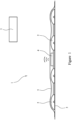
- FIG. 1 shows, in schematic form, a first embodiment of a system 1 according to the invention.
- the system 1 comprises a plurality of protrusions 2 arranged on a substrate 3.
- an active wireless transmitter 4 Arranged between the protrusions 2 is an active wireless transmitter 4.
- the active wireless transmitter 4 is configured to communicate by the Bluetooth short range wireless protocol and so is referred to as a Bluetooth transmitter 4, in particular a Bluetooth beacon 4.
- the protrusions 2 and Bluetooth transmitter 4 are covered in a resin layer 5.
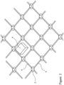
- the protrusions 2 and Bluetooth transmitter 4 are shown in perspective view in figure 2 .
- the protrusions 2 comprise a plurality of half domes 2 arranged in a regular array as shown.
- the domes 2 are connected together by connecting arms 6 which help to retain the domes 2 in fixed relation to each other.
- the domes 2 and connecting arms 6 are arranged on a substrate 3.
- the substrate 3 is typically a portion of a pavement optionally proximate to a crossing point.
- the pavement surface may be any of a variety of materials including tarmac, brick or stone.
- the substrate could be a portion of a railway platform.
- the domes 2 and connecting arms 6 are typically adhered to the substrate 3.
- the Bluetooth transmitter 4 is arranged between the domes 2 and in fixed relation thereto. Typically the Bluetooth transmitter 4 is adhered to the substrate surface. Alternatively the Bluetooth transmitter 4 is arranged in a recess in the substrate 3. Arranging the Bluetooth transmitter 4 in a recess in the substrate 3 has the advantage of providing additional protection to the Bluetooth transmitter 4 however it requires damaging the surface of the substrate 3 which may not be desirable.
- the resin layer 5 may be clear or opaque. It may be coloured or colourless.
- the system 1 further comprises a wireless receiver 7 which is also configured to communicate by the Bluetooth short range wireless protocol and so is referred to as a Bluetooth receiver 7.
- the Bluetooth receiver 7 is a mobile phone which comprises software adapted to employ the Bluetooth functionality of the phone 7.
- the Bluetooth beacon 4 transmits an information signal which comprises a Bluetooth information signal and a Bluetooth ID.
- the operation of Bluetooth is well known and so will not be described in detail.
- the Bluetooth receiver 7 receives the information signal and then generates an alert related to the content of the Bluetooth information portion of the information signal.
- the Bluetooth information signal is converted by the Bluetooth receiver 7 into an alert comprising speech. Examples of such speech are 'the crossing is currently closed for maintenance' or 'You are currently at the crossing on the corner of Street A and Street B'.
- Alternative forms of alert comprise sounds, pictures or video.
- the Bluetooth receiver 7 generates an alert related to the content of the Bluetooth ID portion of the information signal.
- the Bluetooth ID uniquely identifies the Bluetooth beacon 4.
- the Bluetooth receiver 7 can use the Bluetooth ID to generate an alert comprising speech identifying the position of the Bluetooth transmitter 4 and hence the user.
- the Bluetooth receiver 7 is configured to generate an alert related to the strength of at least a portion of the received information signal. This could be the strength of the Bluetooth information signal portion or Bluetooth ID portion or both.
- the Bluetooth receiver 7 is configured to estimate the distance between the Bluetooth transmitter 4 and Bluetooth receiver 7 based on the strength of the portion of the received information signal and generate an alert in the form of speech indicating the range from the Bluetooth transmitter 4. As the user approaches the Bluetooth transmitter 4 multiple alerts are generated indicating the decreasing distance.
- the Bluetooth receiver 7 is configured to provide information to a remote location (typically a server) on receipt of the information signal from the Bluetooth transmitter 4. This could be by SMS or e-mail or other functionality provided by the Bluetooth receiver 7. Typical examples of such information comprise (a) the direction of motion of the Bluetooth receiver 7 relative to the Bluetooth transmitter 4 and (b) confirmation of receipt of the information signal from the Bluetooth transmitter 4 by the Bluetooth receiver 7. In respect of example (a), the Bluetooth receiver 7 will monitor the strength of the information signal over time and from this determine the approximate direction of travel of the Bluetooth receiver 7 and hence the user. Example (b) is particularly useful. From the information provided by the Bluetooth receiver 7 to the server the server is able to determine footfall past an individual Bluetooth transmitter 4. The server can also determiner the travel paths of individual users as they pass multiple Bluetooth transmitters 4.
- the Bluetooth transmitter 4 and Bluetooth receiver 7 are configured to pair together.
- the transmitter 4 is configured to provide information to a remote location (typically a server) on completion of the pairing.
- this information can comprise either or both of (a) the existence of the pairing and (b) the direction of motion of the Bluetooth receiver 7 relative to the Bluetooth transmitter 4.
- example (a) is particularly useful as it enables the server to determine footfall past an individual Bluetooth transmitter 4 and also to determine the path of an individual user as they pass multiple Bluetooth transmitters 4.
- the Bluetooth transmitter 4 is configured such that the information signal can be changed remotely. This can be useful if, for example the crossing is closed for maintenance.
- the Bluetooth transmitter 4 can be reprogrammed so that a user hears a message to this effect when approaching the crossing. When maintenance is complete the information signal can then be returned to its original value.
- the Bluetooth transmitter 4 is configured such that its state can be queried remotely. Typically, the status of a plurality of such Bluetooth transmitters 4 is monitored from a central server and any defective Bluetooth transmitters 4 are replaced when necessary.
- the transmitter 4 and receiver 7 communicate by Bluetooth. Accordingly the transmitter 4 and receiver 7 are referred to as a Bluetooth transmitter 4 and a Bluetooth receiver 7 respectively. In alternative embodiments of the invention the system employs transmitters 4 and receivers 7 which are configured to communicate by other examples of short range wireless protocols. Accordingly, more generally the transmitter 4 and receiver 7 may be referred to as a Protocol transmitter and Protocol receiver respectively. Similarly, more generally the information signal may comprise a Protocol information signal and Protocol ID. Examples of other short range wireless protocols include Zigbee, Z Wave or a custom short range wireless protocol.
- Shown in figure 3 is a further embodiment of a system 1 according to the invention.
- the system 1 comprises a plurality of protrusions 2 arranged on a substrate 3 which is typically a portion of a pavement or a railway platform.
- An active wireless transmitter 4 is arranged on a nearby post 8 in fixed relation to the protrusions 2.
- the wireless transmitter 4 is adapted to transmit an information signal.
- the system further comprises a wireless receiver 7 adapted to receive the information signal and generate an alert in response thereto.
- the transmitter 4 and receiver 7 communicate by Zigbee. Other short range wireless protocols are possible.
- a plurality of active wireless transmitters can be connected to a central computer system.
- the connection is typically wireless.
- the computer system can be accessed by an interface which is typically either a dedicated application or a web based interface.
- the interface typically displays battery life for the active wireless transmitters and also their locations.
- the interface also allows a user to inspect analytic data such as the number of people using a particular crossing and at what times.
- the interface can also be used to program the active wireless transmitters. For example it can be used to change the information signal provided by the at least one active wireless transmitter to the wireless receiver.
Landscapes
- Health & Medical Sciences (AREA)
- General Health & Medical Sciences (AREA)
- Physics & Mathematics (AREA)
- General Physics & Mathematics (AREA)
- Rehabilitation Therapy (AREA)
- Life Sciences & Earth Sciences (AREA)
- Animal Behavior & Ethology (AREA)
- Pain & Pain Management (AREA)
- Public Health (AREA)
- Veterinary Medicine (AREA)
- Epidemiology (AREA)
- Physical Education & Sports Medicine (AREA)
- Engineering & Computer Science (AREA)
- Business, Economics & Management (AREA)
- Audiology, Speech & Language Pathology (AREA)
- Educational Administration (AREA)
- Educational Technology (AREA)
- Theoretical Computer Science (AREA)
- Mobile Radio Communication Systems (AREA)
- Emergency Alarm Devices (AREA)
Description
- The present invention relates to a system for providing information to pedestrians. More particularly, but not exclusively, the present invention relates to a system for providing information to pedestrians comprising a plurality of protrusions, a wireless transmitter and a wireless receiver, the transmitter being adapted to transmit an information signal to the receiver and the receiver being adapted to generate an alert signal in response thereto.
- Systems for providing information to pedestrians are known. Such systems typically find application at crossings and the like where they are of particular use to pedestrians who are blind or who have limited vision. As the pedestrian approaches the crossing they are provided with useful information by the system.
-
PCT/GB2019/051944 - A problem with such a system is that one requires a large number of passive RFID tags to effectively cover the crossing area.
- The present invention seeks to overcome the problems of the prior art.
- Accordingly, the present invention provides a system for providing information to pedestrians comprising a plurality of protrusions;
- at least one active wireless transmitter adapted to transmit an information signal, the at least one wireless transmitter arranged in fixed relation to the protrusions; and,
- a wireless receiver adapted to receive the information signal and generate an alert in response thereto;
- wherein the transmitter and receiver are configured to communicate via a short range wireless protocol;
- wherein the transmitter and receiver comprise a Protocol transmitter and Protocol receiver respectively, the Protocol transmitter being configured to transmit an information signal comprising a Protocol information signal and a Protocol ID;
- wherein the Protocol receiver is configured to provide information to a remote location on receipt of the information signal from the Protocol transmitter;
- the information provided by the Protocol receiver comprising at least one of (a) the direction of motion of the Protocol receiver relative to the Protocol transmitter and (b) confirmation of receipt of the information signal from the Protocol transmitter by the Protocol receiver.
- The system according to the invention employs at least one active transmitter. Only a small number of such transmitters, possibly only one such transmitter, are therefore required. This substantially reduces installation cost, increases ease of installation and increases the reliability of the system.
- Preferably the wireless transmitter is arranged between at least two of the plurality of protrusions.
- Preferably the system further comprises a substrate, the plurality of protrusions and the transmitter being arranged on the substrate.
- Preferably the substrate is a portion of a pavement.
- Alternatively, the substrate is a portion of a railway platform.
- Preferably the protrusions are connected together by connecting arms.
- Preferably the system further comprises a resin layer covering the protrusions and transmitter.
- Preferably the wireless receiver is a mobile phone.
- Preferably the alert comprises at least one of a sound, speech, an image or video.
- Preferably the transmitter is configured such that the information signal can be changed remotely.
- Preferably the transmitter is configured such that it can be queried remotely.
- Preferably the receiver is configured to generate an alert related to the strength of at least a portion of the received information signal.
- Preferably the receiver is configured to generate an alert related to the content of at least a portion of the information signal.
- Preferably the Protocol transmitter and Protocol receiver are configured to pair together.
- Preferably the Protocol receiver is configured to provide information to a remote location on completion of the pairing, the information comprising at least one of (a) the existence of the pairing and (b) the direction of motion of the Protocol receiver relative to the Protocol transmitter.
- Preferably the short range wireless protocol is Bluetooth
- Alternatively the short range wireless protocol is any one of Zigbee, Z Wave or a custom short range wireless protocol.
- The present invention will now be described by way of example only and not in any limitative sense with reference to the accompanying figures in which
-
Figure 1 shows a system according to the invention in schematic form; -
Figure 2 shows the protrusions and transmitter of the system offigure 1 arranged on a substrate; and, -
Figure 3 shows a further embodiment of a system according to the invention. -
Figure 1 shows, in schematic form, a first embodiment of asystem 1 according to the invention. Thesystem 1 comprises a plurality ofprotrusions 2 arranged on asubstrate 3. Arranged between theprotrusions 2 is an activewireless transmitter 4. In this embodiment the activewireless transmitter 4 is configured to communicate by the Bluetooth short range wireless protocol and so is referred to as a Bluetoothtransmitter 4, in particular a Bluetoothbeacon 4. Theprotrusions 2 and Bluetoothtransmitter 4 are covered in aresin layer 5. - The
protrusions 2 and Bluetoothtransmitter 4 are shown in perspective view infigure 2 . Theprotrusions 2 comprise a plurality ofhalf domes 2 arranged in a regular array as shown. Thedomes 2 are connected together by connectingarms 6 which help to retain thedomes 2 in fixed relation to each other. - The
domes 2 and connectingarms 6 are arranged on asubstrate 3. Thesubstrate 3 is typically a portion of a pavement optionally proximate to a crossing point. The pavement surface may be any of a variety of materials including tarmac, brick or stone. Alternatively the substrate could be a portion of a railway platform. Thedomes 2 and connectingarms 6 are typically adhered to thesubstrate 3. - The Bluetooth
transmitter 4 is arranged between thedomes 2 and in fixed relation thereto. Typically the Bluetoothtransmitter 4 is adhered to the substrate surface. Alternatively the Bluetoothtransmitter 4 is arranged in a recess in thesubstrate 3. Arranging the Bluetoothtransmitter 4 in a recess in thesubstrate 3 has the advantage of providing additional protection to the Bluetoothtransmitter 4 however it requires damaging the surface of thesubstrate 3 which may not be desirable. - Once the
protrusions 2 and Bluetoothtransmitter 4 are in place they are preferably covered with aresin layer 5 which provides protection to theprotrusions 2 and Bluetoothtransmitter 4. Theresin layer 5 may be clear or opaque. It may be coloured or colourless. - Returning back to
figure 1 , thesystem 1 further comprises awireless receiver 7 which is also configured to communicate by the Bluetooth short range wireless protocol and so is referred to as aBluetooth receiver 7. In this embodiment theBluetooth receiver 7 is a mobile phone which comprises software adapted to employ the Bluetooth functionality of thephone 7. - In use a user carrying the
phone 7 approaches a crossing. The user will know they are proximate to the crossing when they feel theprotrusions 2 under their feet. This is a signal to the user to activate the software on thephone 7 if it is not already running. TheBluetooth beacon 4 transmits an information signal which comprises a Bluetooth information signal and a Bluetooth ID. The operation of Bluetooth is well known and so will not be described in detail. TheBluetooth receiver 7 receives the information signal and then generates an alert related to the content of the Bluetooth information portion of the information signal. Typically the Bluetooth information signal is converted by theBluetooth receiver 7 into an alert comprising speech. Examples of such speech are 'the crossing is currently closed for maintenance' or 'You are currently at the crossing on the corner of Street A and Street B'. Alternative forms of alert comprise sounds, pictures or video. - In a further embodiment of the invention the
Bluetooth receiver 7 generates an alert related to the content of the Bluetooth ID portion of the information signal. The Bluetooth ID uniquely identifies theBluetooth beacon 4. By use of an appropriate look up table which converts Bluetooth ID into geographical location theBluetooth receiver 7 can use the Bluetooth ID to generate an alert comprising speech identifying the position of theBluetooth transmitter 4 and hence the user. - In a further embodiment of the invention the
Bluetooth receiver 7 is configured to generate an alert related to the strength of at least a portion of the received information signal. This could be the strength of the Bluetooth information signal portion or Bluetooth ID portion or both. TheBluetooth receiver 7 is configured to estimate the distance between theBluetooth transmitter 4 andBluetooth receiver 7 based on the strength of the portion of the received information signal and generate an alert in the form of speech indicating the range from theBluetooth transmitter 4. As the user approaches theBluetooth transmitter 4 multiple alerts are generated indicating the decreasing distance. - The
Bluetooth receiver 7 is configured to provide information to a remote location (typically a server) on receipt of the information signal from theBluetooth transmitter 4. This could be by SMS or e-mail or other functionality provided by theBluetooth receiver 7. Typical examples of such information comprise (a) the direction of motion of theBluetooth receiver 7 relative to theBluetooth transmitter 4 and (b) confirmation of receipt of the information signal from theBluetooth transmitter 4 by theBluetooth receiver 7. In respect of example (a), theBluetooth receiver 7 will monitor the strength of the information signal over time and from this determine the approximate direction of travel of theBluetooth receiver 7 and hence the user. Example (b) is particularly useful. From the information provided by theBluetooth receiver 7 to the server the server is able to determine footfall past anindividual Bluetooth transmitter 4. The server can also determiner the travel paths of individual users as they passmultiple Bluetooth transmitters 4. - In a further embodiment of the invention the
Bluetooth transmitter 4 andBluetooth receiver 7 are configured to pair together. This enables theBluetooth transmitter 4 to provide additional functionality. In this embodiment thetransmitter 4 is configured to provide information to a remote location (typically a server) on completion of the pairing. By way of example this information can comprise either or both of (a) the existence of the pairing and (b) the direction of motion of theBluetooth receiver 7 relative to theBluetooth transmitter 4. As above, example (a) is particularly useful as it enables the server to determine footfall past anindividual Bluetooth transmitter 4 and also to determine the path of an individual user as they passmultiple Bluetooth transmitters 4. - In each of the above embodiments it is preferable that the
Bluetooth transmitter 4 is configured such that the information signal can be changed remotely. This can be useful if, for example the crossing is closed for maintenance. TheBluetooth transmitter 4 can be reprogrammed so that a user hears a message to this effect when approaching the crossing. When maintenance is complete the information signal can then be returned to its original value. - In each of the above embodiments it is also preferable that the
Bluetooth transmitter 4 is configured such that its state can be queried remotely. Typically, the status of a plurality ofsuch Bluetooth transmitters 4 is monitored from a central server and anydefective Bluetooth transmitters 4 are replaced when necessary. - In all of the above embodiments the
transmitter 4 andreceiver 7 communicate by Bluetooth. Accordingly thetransmitter 4 andreceiver 7 are referred to as aBluetooth transmitter 4 and aBluetooth receiver 7 respectively. In alternative embodiments of the invention the system employstransmitters 4 andreceivers 7 which are configured to communicate by other examples of short range wireless protocols. Accordingly, more generally thetransmitter 4 andreceiver 7 may be referred to as a Protocol transmitter and Protocol receiver respectively. Similarly, more generally the information signal may comprise a Protocol information signal and Protocol ID. Examples of other short range wireless protocols include Zigbee, Z Wave or a custom short range wireless protocol. - Shown in
figure 3 is a further embodiment of asystem 1 according to the invention. As before thesystem 1 comprises a plurality ofprotrusions 2 arranged on asubstrate 3 which is typically a portion of a pavement or a railway platform. Anactive wireless transmitter 4 is arranged on anearby post 8 in fixed relation to theprotrusions 2. Thewireless transmitter 4 is adapted to transmit an information signal. The system further comprises awireless receiver 7 adapted to receive the information signal and generate an alert in response thereto. In this embodiment thetransmitter 4 andreceiver 7 communicate by Zigbee. Other short range wireless protocols are possible. - A plurality of active wireless transmitters can be connected to a central computer system. The connection is typically wireless. The computer system can be accessed by an interface which is typically either a dedicated application or a web based interface. The interface typically displays battery life for the active wireless transmitters and also their locations. The interface also allows a user to inspect analytic data such as the number of people using a particular crossing and at what times. The interface can also be used to program the active wireless transmitters. For example it can be used to change the information signal provided by the at least one active wireless transmitter to the wireless receiver.
Claims (17)
- A system (1) for providing information to pedestrians comprisinga plurality of protrusions (2);at least one active wireless transmitter (4) adapted to transmit an information signal, the at least one wireless transmitter (4) arranged in fixed relation to the protrusions (2); and,a wireless receiver (7) adapted to receive the information signal and generate an alert in response thereto;wherein the transmitter (4) and receiver (7) are configured to communicate via a short range wireless protocol;wherein the transmitter (4) and receiver (7) comprise a Protocol transmitter (4) and Protocol receiver (7) respectively, the Protocol transmitter (4) being configured to transmit an information signal comprising a Protocol information signal and a Protocol ID;wherein the Protocol receiver (7) is configured to provide information to a remote location on receipt of the information signal from the Protocol transmitter (4);the information provided by the Protocol receiver (7) comprising at least one of (a) the direction of motion of the Protocol receiver (7) relative to the Protocol transmitter (4) and (b) confirmation of receipt of the information signal from the Protocol transmitter (4) by the Protocol receiver (7).
- A system (1) as claimed in claim 1 wherein the wireless transmitter (4) is arranged between at least two of the plurality of protrusions (2).
- A system (1) as claimed in either of claims 1 or 2, further comprising a substrate (3), the plurality of protrusions (2) and the transmitter (4) being arranged on the substrate (3).
- A system (1) as claimed in claim 3, wherein the substrate (3) is a portion of a pavement.
- A system (1) as claimed in claim 3, wherein the substrate (3) is a portion of a railway platform.
- A system (1) as claimed in any one of claims 1 to 5, wherein the protrusions (2) are connected together by connecting arms (6).
- A system (1) as claimed in any one of claims 1 to 6, further comprising a resin layer (5) covering the protrusions (2) and transmitter (4).
- A system (1) as claimed in any one of claims 1 to 7, wherein the wireless receiver (7) is a mobile phone.
- A system (1) as claimed in any one of claims 1 to 8, wherein the alert comprises at least one of a sound, speech, an image or video.
- A system (1) as claimed in any one of claims 1 to 9, wherein the transmitter (4) is configured such that the information signal can be changed remotely.
- A system (1) as claimed in any one of claims 1 to 10, wherein the transmitter (4) is configured such that it can be queried remotely.
- A system (1) as claimed in any one of claims 1 to 11, wherein the receiver (7) is configured to generate an alert related to the strength of at least a portion of the received information signal.
- A system (1) as claimed in any one of claims 1 to 12, wherein the receiver (7) is configured to generate an alert related to the content of at least a portion of the information signal.
- A system (1) as claimed in claim 1, wherein the Protocol transmitter (4) and Protocol receiver (7) are configured to pair together.
- A system (1) as claimed in claim 14, wherein the Protocol receiver (7) is configured to provide information to a remote location on completion of the pairing, the information comprising at least one of (a) the existence of the pairing and (b) the direction of motion of the Protocol receiver (7) relative to the Protocol transmitter (4).
- A system (1) as claimed in any one of claims 1 to 15, wherein the short range wireless protocol is Bluetooth.
- A system as claimed in any one of claims 1 to 15, wherein the short range wireless protocol is any one of Zigbee, Z Wave or a custom short range wireless protocol.
Applications Claiming Priority (2)
| Application Number | Priority Date | Filing Date | Title |
|---|---|---|---|
| GBGB2100326.4A GB202100326D0 (en) | 2021-01-11 | 2021-01-11 | A system of providing information to pedestrians |
| GB2114361.5A GB2604206A (en) | 2021-01-11 | 2021-10-07 | A system for providing information to pedestrians |
Publications (2)
| Publication Number | Publication Date |
|---|---|
| EP4029488A1 EP4029488A1 (en) | 2022-07-20 |
| EP4029488B1 true EP4029488B1 (en) | 2024-05-08 |
Family
ID=80118780
Family Applications (1)
| Application Number | Title | Priority Date | Filing Date |
|---|---|---|---|
| EP22150894.8A Active EP4029488B1 (en) | 2021-01-11 | 2022-01-11 | A system for providing information to pedestrians |
Country Status (1)
| Country | Link |
|---|---|
| EP (1) | EP4029488B1 (en) |
Families Citing this family (1)
| Publication number | Priority date | Publication date | Assignee | Title |
|---|---|---|---|---|
| DE202022105734U1 (en) | 2022-10-11 | 2022-11-07 | Ralph Schulze | warning system |
Family Cites Families (4)
| Publication number | Priority date | Publication date | Assignee | Title |
|---|---|---|---|---|
| KR100643336B1 (en) * | 2004-12-16 | 2006-11-15 | 이효숙 | Visually handicapped sidewalk block and system |
| CN102261179A (en) * | 2010-05-28 | 2011-11-30 | 陈浚 | Blind guiding floor, blind guiding system and blind guiding method |
| US11612538B2 (en) * | 2018-05-14 | 2023-03-28 | Brandbumps, Llc | Tactile warning panel system with geothermal system |
| GB2575506A (en) * | 2018-07-13 | 2020-01-15 | Robert Pearson Stephen | User interface device |
-
2022
- 2022-01-11 EP EP22150894.8A patent/EP4029488B1/en active Active
Also Published As
| Publication number | Publication date |
|---|---|
| EP4029488A1 (en) | 2022-07-20 |
Similar Documents
| Publication | Publication Date | Title |
|---|---|---|
| Kanan et al. | An IoT-based autonomous system for workers' safety in construction sites with real-time alarming, monitoring, and positioning strategies | |
| US12061946B2 (en) | Package sealing tape types with varied transducer sampling densities | |
| EP1810049B1 (en) | Navigation system for disabled persons, in particular visually impaired persons | |
| KR100982398B1 (en) | State monitoring system using zigbee and cctv | |
| US20060129308A1 (en) | Management and navigation system for the blind | |
| CN101694519A (en) | Positioning system and positioning method thereof | |
| GB2440583A (en) | A portable route planning and object identification device for the visually impaired | |
| WO2019118440A1 (en) | Flexible adhesive tape platform for wireless transducing circuits and applications | |
| EP4029488A1 (en) | A system for providing information to pedestrians | |
| JP2009515427A (en) | Radio frequency locator system | |
| KR101791639B1 (en) | Emergency call system using beacon and mobile terminal | |
| US7085568B2 (en) | Provision of local data in a wireless system | |
| KR20040087226A (en) | Notice method for emergent dispatch using mobile communication device | |
| GB2604206A (en) | A system for providing information to pedestrians | |
| CN107105411A (en) | A kind of mobile intelligent terminal track monitoring system and method based on intelligent switch panel | |
| KR20160064417A (en) | System for Preventing a Calamity based on Beacon and Controlling Meathod for the Same | |
| CN100548005C (en) | Mobile terminal for providing atmospheric condition information | |
| KR101470105B1 (en) | Intelligent System for Managing Members in a Group | |
| US20190164401A1 (en) | Object tracking system | |
| KR101066561B1 (en) | Location tracking system and method | |
| JP2011258109A (en) | Sensing method and sensor network system | |
| KR102009964B1 (en) | System and Method for Location Information Services using BLE Transmitter and Receiver | |
| KR101468562B1 (en) | System and method for providing realtime reporting services using Near Field Communication | |
| KR20160144763A (en) | Method for searching lost child using beacone | |
| KR100824727B1 (en) | Location Information Service System and Method in Complex Using LBS |
Legal Events
| Date | Code | Title | Description |
|---|---|---|---|
| PUAI | Public reference made under article 153(3) epc to a published international application that has entered the european phase |
Free format text: ORIGINAL CODE: 0009012 |
|
| STAA | Information on the status of an ep patent application or granted ep patent |
Free format text: STATUS: THE APPLICATION HAS BEEN PUBLISHED |
|
| AK | Designated contracting states |
Kind code of ref document: A1 Designated state(s): AL AT BE BG CH CY CZ DE DK EE ES FI FR GB GR HR HU IE IS IT LI LT LU LV MC MK MT NL NO PL PT RO RS SE SI SK SM TR |
|
| STAA | Information on the status of an ep patent application or granted ep patent |
Free format text: STATUS: REQUEST FOR EXAMINATION WAS MADE |
|
| 17P | Request for examination filed |
Effective date: 20230120 |
|
| RBV | Designated contracting states (corrected) |
Designated state(s): AL AT BE BG CH CY CZ DE DK EE ES FI FR GB GR HR HU IE IS IT LI LT LU LV MC MK MT NL NO PL PT RO RS SE SI SK SM TR |
|
| GRAP | Despatch of communication of intention to grant a patent |
Free format text: ORIGINAL CODE: EPIDOSNIGR1 |
|
| STAA | Information on the status of an ep patent application or granted ep patent |
Free format text: STATUS: GRANT OF PATENT IS INTENDED |
|
| RIC1 | Information provided on ipc code assigned before grant |
Ipc: G08G 1/02 20060101ALI20231031BHEP Ipc: G09B 21/00 20060101ALI20231031BHEP Ipc: G08G 1/005 20060101ALI20231031BHEP Ipc: A61H 3/06 20060101AFI20231031BHEP |
|
| INTG | Intention to grant announced |
Effective date: 20231130 |
|
| GRAS | Grant fee paid |
Free format text: ORIGINAL CODE: EPIDOSNIGR3 |
|
| GRAA | (expected) grant |
Free format text: ORIGINAL CODE: 0009210 |
|
| STAA | Information on the status of an ep patent application or granted ep patent |
Free format text: STATUS: THE PATENT HAS BEEN GRANTED |
|
| AK | Designated contracting states |
Kind code of ref document: B1 Designated state(s): AL AT BE BG CH CY CZ DE DK EE ES FI FR GB GR HR HU IE IS IT LI LT LU LV MC MK MT NL NO PL PT RO RS SE SI SK SM TR |
|
| REG | Reference to a national code |
Ref country code: GB Ref legal event code: FG4D |
|
| REG | Reference to a national code |
Ref country code: CH Ref legal event code: EP |
|
| REG | Reference to a national code |
Ref country code: DE Ref legal event code: R096 Ref document number: 602022003256 Country of ref document: DE |
|
| REG | Reference to a national code |
Ref country code: IE Ref legal event code: FG4D |
|
| REG | Reference to a national code |
Ref country code: NL Ref legal event code: FP |
|
| REG | Reference to a national code |
Ref country code: LT Ref legal event code: MG9D |
|
| PG25 | Lapsed in a contracting state [announced via postgrant information from national office to epo] |
Ref country code: IS Free format text: LAPSE BECAUSE OF FAILURE TO SUBMIT A TRANSLATION OF THE DESCRIPTION OR TO PAY THE FEE WITHIN THE PRESCRIBED TIME-LIMIT Effective date: 20240908 |
|
| PG25 | Lapsed in a contracting state [announced via postgrant information from national office to epo] |
Ref country code: BG Free format text: LAPSE BECAUSE OF FAILURE TO SUBMIT A TRANSLATION OF THE DESCRIPTION OR TO PAY THE FEE WITHIN THE PRESCRIBED TIME-LIMIT Effective date: 20240508 |
|
| PG25 | Lapsed in a contracting state [announced via postgrant information from national office to epo] |
Ref country code: HR Free format text: LAPSE BECAUSE OF FAILURE TO SUBMIT A TRANSLATION OF THE DESCRIPTION OR TO PAY THE FEE WITHIN THE PRESCRIBED TIME-LIMIT Effective date: 20240508 Ref country code: FI Free format text: LAPSE BECAUSE OF FAILURE TO SUBMIT A TRANSLATION OF THE DESCRIPTION OR TO PAY THE FEE WITHIN THE PRESCRIBED TIME-LIMIT Effective date: 20240508 |
|
| PG25 | Lapsed in a contracting state [announced via postgrant information from national office to epo] |
Ref country code: GR Free format text: LAPSE BECAUSE OF FAILURE TO SUBMIT A TRANSLATION OF THE DESCRIPTION OR TO PAY THE FEE WITHIN THE PRESCRIBED TIME-LIMIT Effective date: 20240809 |
|
| PG25 | Lapsed in a contracting state [announced via postgrant information from national office to epo] |
Ref country code: PT Free format text: LAPSE BECAUSE OF FAILURE TO SUBMIT A TRANSLATION OF THE DESCRIPTION OR TO PAY THE FEE WITHIN THE PRESCRIBED TIME-LIMIT Effective date: 20240909 |
|
| REG | Reference to a national code |
Ref country code: AT Ref legal event code: MK05 Ref document number: 1684425 Country of ref document: AT Kind code of ref document: T Effective date: 20240508 |
|
| PG25 | Lapsed in a contracting state [announced via postgrant information from national office to epo] |
Ref country code: ES Free format text: LAPSE BECAUSE OF FAILURE TO SUBMIT A TRANSLATION OF THE DESCRIPTION OR TO PAY THE FEE WITHIN THE PRESCRIBED TIME-LIMIT Effective date: 20240508 |
|
| PG25 | Lapsed in a contracting state [announced via postgrant information from national office to epo] |
Ref country code: AT Free format text: LAPSE BECAUSE OF FAILURE TO SUBMIT A TRANSLATION OF THE DESCRIPTION OR TO PAY THE FEE WITHIN THE PRESCRIBED TIME-LIMIT Effective date: 20240508 |
|
| PG25 | Lapsed in a contracting state [announced via postgrant information from national office to epo] |
Ref country code: PL Free format text: LAPSE BECAUSE OF FAILURE TO SUBMIT A TRANSLATION OF THE DESCRIPTION OR TO PAY THE FEE WITHIN THE PRESCRIBED TIME-LIMIT Effective date: 20240508 |
|
| PG25 | Lapsed in a contracting state [announced via postgrant information from national office to epo] |
Ref country code: LV Free format text: LAPSE BECAUSE OF FAILURE TO SUBMIT A TRANSLATION OF THE DESCRIPTION OR TO PAY THE FEE WITHIN THE PRESCRIBED TIME-LIMIT Effective date: 20240508 |
|
| RAP4 | Party data changed (patent owner data changed or rights of a patent transferred) |
Owner name: CONNOR SPECIALIST PAVING LIMITED |
|
| PG25 | Lapsed in a contracting state [announced via postgrant information from national office to epo] |
Ref country code: PT Free format text: LAPSE BECAUSE OF FAILURE TO SUBMIT A TRANSLATION OF THE DESCRIPTION OR TO PAY THE FEE WITHIN THE PRESCRIBED TIME-LIMIT Effective date: 20240909 Ref country code: PL Free format text: LAPSE BECAUSE OF FAILURE TO SUBMIT A TRANSLATION OF THE DESCRIPTION OR TO PAY THE FEE WITHIN THE PRESCRIBED TIME-LIMIT Effective date: 20240508 Ref country code: NO Free format text: LAPSE BECAUSE OF FAILURE TO SUBMIT A TRANSLATION OF THE DESCRIPTION OR TO PAY THE FEE WITHIN THE PRESCRIBED TIME-LIMIT Effective date: 20240808 Ref country code: LV Free format text: LAPSE BECAUSE OF FAILURE TO SUBMIT A TRANSLATION OF THE DESCRIPTION OR TO PAY THE FEE WITHIN THE PRESCRIBED TIME-LIMIT Effective date: 20240508 Ref country code: IS Free format text: LAPSE BECAUSE OF FAILURE TO SUBMIT A TRANSLATION OF THE DESCRIPTION OR TO PAY THE FEE WITHIN THE PRESCRIBED TIME-LIMIT Effective date: 20240908 Ref country code: HR Free format text: LAPSE BECAUSE OF FAILURE TO SUBMIT A TRANSLATION OF THE DESCRIPTION OR TO PAY THE FEE WITHIN THE PRESCRIBED TIME-LIMIT Effective date: 20240508 Ref country code: GR Free format text: LAPSE BECAUSE OF FAILURE TO SUBMIT A TRANSLATION OF THE DESCRIPTION OR TO PAY THE FEE WITHIN THE PRESCRIBED TIME-LIMIT Effective date: 20240809 Ref country code: FI Free format text: LAPSE BECAUSE OF FAILURE TO SUBMIT A TRANSLATION OF THE DESCRIPTION OR TO PAY THE FEE WITHIN THE PRESCRIBED TIME-LIMIT Effective date: 20240508 Ref country code: ES Free format text: LAPSE BECAUSE OF FAILURE TO SUBMIT A TRANSLATION OF THE DESCRIPTION OR TO PAY THE FEE WITHIN THE PRESCRIBED TIME-LIMIT Effective date: 20240508 Ref country code: BG Free format text: LAPSE BECAUSE OF FAILURE TO SUBMIT A TRANSLATION OF THE DESCRIPTION OR TO PAY THE FEE WITHIN THE PRESCRIBED TIME-LIMIT Effective date: 20240508 Ref country code: AT Free format text: LAPSE BECAUSE OF FAILURE TO SUBMIT A TRANSLATION OF THE DESCRIPTION OR TO PAY THE FEE WITHIN THE PRESCRIBED TIME-LIMIT Effective date: 20240508 Ref country code: RS Free format text: LAPSE BECAUSE OF FAILURE TO SUBMIT A TRANSLATION OF THE DESCRIPTION OR TO PAY THE FEE WITHIN THE PRESCRIBED TIME-LIMIT Effective date: 20240808 |
|
| PG25 | Lapsed in a contracting state [announced via postgrant information from national office to epo] |
Ref country code: DK Free format text: LAPSE BECAUSE OF FAILURE TO SUBMIT A TRANSLATION OF THE DESCRIPTION OR TO PAY THE FEE WITHIN THE PRESCRIBED TIME-LIMIT Effective date: 20240508 |
|
| PG25 | Lapsed in a contracting state [announced via postgrant information from national office to epo] |
Ref country code: EE Free format text: LAPSE BECAUSE OF FAILURE TO SUBMIT A TRANSLATION OF THE DESCRIPTION OR TO PAY THE FEE WITHIN THE PRESCRIBED TIME-LIMIT Effective date: 20240508 |
|
| PG25 | Lapsed in a contracting state [announced via postgrant information from national office to epo] |
Ref country code: CZ Free format text: LAPSE BECAUSE OF FAILURE TO SUBMIT A TRANSLATION OF THE DESCRIPTION OR TO PAY THE FEE WITHIN THE PRESCRIBED TIME-LIMIT Effective date: 20240508 |
|
| PG25 | Lapsed in a contracting state [announced via postgrant information from national office to epo] |
Ref country code: SK Free format text: LAPSE BECAUSE OF FAILURE TO SUBMIT A TRANSLATION OF THE DESCRIPTION OR TO PAY THE FEE WITHIN THE PRESCRIBED TIME-LIMIT Effective date: 20240508 Ref country code: RO Free format text: LAPSE BECAUSE OF FAILURE TO SUBMIT A TRANSLATION OF THE DESCRIPTION OR TO PAY THE FEE WITHIN THE PRESCRIBED TIME-LIMIT Effective date: 20240508 |
|
| PG25 | Lapsed in a contracting state [announced via postgrant information from national office to epo] |
Ref country code: SM Free format text: LAPSE BECAUSE OF FAILURE TO SUBMIT A TRANSLATION OF THE DESCRIPTION OR TO PAY THE FEE WITHIN THE PRESCRIBED TIME-LIMIT Effective date: 20240508 |
|
| PG25 | Lapsed in a contracting state [announced via postgrant information from national office to epo] |
Ref country code: SM Free format text: LAPSE BECAUSE OF FAILURE TO SUBMIT A TRANSLATION OF THE DESCRIPTION OR TO PAY THE FEE WITHIN THE PRESCRIBED TIME-LIMIT Effective date: 20240508 Ref country code: SK Free format text: LAPSE BECAUSE OF FAILURE TO SUBMIT A TRANSLATION OF THE DESCRIPTION OR TO PAY THE FEE WITHIN THE PRESCRIBED TIME-LIMIT Effective date: 20240508 Ref country code: RO Free format text: LAPSE BECAUSE OF FAILURE TO SUBMIT A TRANSLATION OF THE DESCRIPTION OR TO PAY THE FEE WITHIN THE PRESCRIBED TIME-LIMIT Effective date: 20240508 Ref country code: EE Free format text: LAPSE BECAUSE OF FAILURE TO SUBMIT A TRANSLATION OF THE DESCRIPTION OR TO PAY THE FEE WITHIN THE PRESCRIBED TIME-LIMIT Effective date: 20240508 Ref country code: DK Free format text: LAPSE BECAUSE OF FAILURE TO SUBMIT A TRANSLATION OF THE DESCRIPTION OR TO PAY THE FEE WITHIN THE PRESCRIBED TIME-LIMIT Effective date: 20240508 Ref country code: CZ Free format text: LAPSE BECAUSE OF FAILURE TO SUBMIT A TRANSLATION OF THE DESCRIPTION OR TO PAY THE FEE WITHIN THE PRESCRIBED TIME-LIMIT Effective date: 20240508 |
|
| PG25 | Lapsed in a contracting state [announced via postgrant information from national office to epo] |
Ref country code: IT Free format text: LAPSE BECAUSE OF FAILURE TO SUBMIT A TRANSLATION OF THE DESCRIPTION OR TO PAY THE FEE WITHIN THE PRESCRIBED TIME-LIMIT Effective date: 20240508 |
|
| REG | Reference to a national code |
Ref country code: DE Ref legal event code: R097 Ref document number: 602022003256 Country of ref document: DE |
|
| PLBE | No opposition filed within time limit |
Free format text: ORIGINAL CODE: 0009261 |
|
| STAA | Information on the status of an ep patent application or granted ep patent |
Free format text: STATUS: NO OPPOSITION FILED WITHIN TIME LIMIT |
|
| 26N | No opposition filed |
Effective date: 20250211 |
|
| PG25 | Lapsed in a contracting state [announced via postgrant information from national office to epo] |
Ref country code: SI Free format text: LAPSE BECAUSE OF FAILURE TO SUBMIT A TRANSLATION OF THE DESCRIPTION OR TO PAY THE FEE WITHIN THE PRESCRIBED TIME-LIMIT Effective date: 20240508 |
|
| REG | Reference to a national code |
Ref country code: CH Ref legal event code: PL |
|
| PG25 | Lapsed in a contracting state [announced via postgrant information from national office to epo] |
Ref country code: SE Free format text: LAPSE BECAUSE OF FAILURE TO SUBMIT A TRANSLATION OF THE DESCRIPTION OR TO PAY THE FEE WITHIN THE PRESCRIBED TIME-LIMIT Effective date: 20240508 |
|
| PG25 | Lapsed in a contracting state [announced via postgrant information from national office to epo] |
Ref country code: LU Free format text: LAPSE BECAUSE OF NON-PAYMENT OF DUE FEES Effective date: 20250111 Ref country code: MC Free format text: LAPSE BECAUSE OF FAILURE TO SUBMIT A TRANSLATION OF THE DESCRIPTION OR TO PAY THE FEE WITHIN THE PRESCRIBED TIME-LIMIT Effective date: 20240508 |
|
| PG25 | Lapsed in a contracting state [announced via postgrant information from national office to epo] |
Ref country code: BE Free format text: LAPSE BECAUSE OF NON-PAYMENT OF DUE FEES Effective date: 20250131 |
|
| PG25 | Lapsed in a contracting state [announced via postgrant information from national office to epo] |
Ref country code: CH Free format text: LAPSE BECAUSE OF NON-PAYMENT OF DUE FEES Effective date: 20250131 |
|
| REG | Reference to a national code |
Ref country code: BE Ref legal event code: MM Effective date: 20250131 |
|
| PGFP | Annual fee paid to national office [announced via postgrant information from national office to epo] |
Ref country code: NL Payment date: 20251215 Year of fee payment: 5 Ref country code: FR Payment date: 20251230 Year of fee payment: 5 |
|
| PGFP | Annual fee paid to national office [announced via postgrant information from national office to epo] |
Ref country code: IE Payment date: 20251217 Year of fee payment: 5 |
|
| PGFP | Annual fee paid to national office [announced via postgrant information from national office to epo] |
Ref country code: GB Payment date: 20260219 Year of fee payment: 5 |
|
| PGFP | Annual fee paid to national office [announced via postgrant information from national office to epo] |
Ref country code: DE Payment date: 20251217 Year of fee payment: 5 |
|
| PG25 | Lapsed in a contracting state [announced via postgrant information from national office to epo] |
Ref country code: CY Free format text: LAPSE BECAUSE OF FAILURE TO SUBMIT A TRANSLATION OF THE DESCRIPTION OR TO PAY THE FEE WITHIN THE PRESCRIBED TIME-LIMIT Effective date: 20240508 |
|
| PG25 | Lapsed in a contracting state [announced via postgrant information from national office to epo] |
Ref country code: TR Free format text: LAPSE BECAUSE OF FAILURE TO SUBMIT A TRANSLATION OF THE DESCRIPTION OR TO PAY THE FEE WITHIN THE PRESCRIBED TIME-LIMIT Effective date: 20240508 |
|
| PG25 | Lapsed in a contracting state [announced via postgrant information from national office to epo] |
Ref country code: LT Free format text: LAPSE BECAUSE OF FAILURE TO SUBMIT A TRANSLATION OF THE DESCRIPTION OR TO PAY THE FEE WITHIN THE PRESCRIBED TIME-LIMIT Effective date: 20240508 |