EP4029415B1 - Power supply base with vibration touch keys - Google Patents
Power supply base with vibration touch keys Download PDFInfo
- Publication number
- EP4029415B1 EP4029415B1 EP21204262.6A EP21204262A EP4029415B1 EP 4029415 B1 EP4029415 B1 EP 4029415B1 EP 21204262 A EP21204262 A EP 21204262A EP 4029415 B1 EP4029415 B1 EP 4029415B1
- Authority
- EP
- European Patent Office
- Prior art keywords
- lamp strip
- touch
- transparent ring
- ring
- post
- Prior art date
- Legal status (The legal status is an assumption and is not a legal conclusion. Google has not performed a legal analysis and makes no representation as to the accuracy of the status listed.)
- Active
Links
Images





Classifications
-
- H—ELECTRICITY
- H01—ELECTRIC ELEMENTS
- H01R—ELECTRICALLY-CONDUCTIVE CONNECTIONS; STRUCTURAL ASSOCIATIONS OF A PLURALITY OF MUTUALLY-INSULATED ELECTRICAL CONNECTING ELEMENTS; COUPLING DEVICES; CURRENT COLLECTORS
- H01R13/00—Details of coupling devices of the kinds covered by groups H01R12/70 or H01R24/00 - H01R33/00
- H01R13/02—Contact members
- H01R13/10—Sockets for co-operation with pins or blades
-
- H—ELECTRICITY
- H03—ELECTRONIC CIRCUITRY
- H03K—PULSE TECHNIQUE
- H03K17/00—Electronic switching or gating, i.e. not by contact-making and –breaking
- H03K17/94—Electronic switching or gating, i.e. not by contact-making and –breaking characterised by the way in which the control signals are generated
- H03K17/96—Touch switches
- H03K17/962—Capacitive touch switches
- H03K17/9622—Capacitive touch switches using a plurality of detectors, e.g. keyboard
-
- H—ELECTRICITY
- H01—ELECTRIC ELEMENTS
- H01R—ELECTRICALLY-CONDUCTIVE CONNECTIONS; STRUCTURAL ASSOCIATIONS OF A PLURALITY OF MUTUALLY-INSULATED ELECTRICAL CONNECTING ELEMENTS; COUPLING DEVICES; CURRENT COLLECTORS
- H01R13/00—Details of coupling devices of the kinds covered by groups H01R12/70 or H01R24/00 - H01R33/00
- H01R13/66—Structural association with built-in electrical component
- H01R13/70—Structural association with built-in electrical component with built-in switch
-
- A—HUMAN NECESSITIES
- A47—FURNITURE; DOMESTIC ARTICLES OR APPLIANCES; COFFEE MILLS; SPICE MILLS; SUCTION CLEANERS IN GENERAL
- A47J—KITCHEN EQUIPMENT; COFFEE MILLS; SPICE MILLS; APPARATUS FOR MAKING BEVERAGES
- A47J27/00—Cooking-vessels
- A47J27/21—Water-boiling vessels, e.g. kettles
- A47J27/21008—Water-boiling vessels, e.g. kettles electrically heated
- A47J27/2105—Water-boiling vessels, e.g. kettles electrically heated of the cordless type, i.e. whereby the water vessel can be plugged into an electrically-powered base element
-
- G—PHYSICS
- G06—COMPUTING OR CALCULATING; COUNTING
- G06F—ELECTRIC DIGITAL DATA PROCESSING
- G06F3/00—Input arrangements for transferring data to be processed into a form capable of being handled by the computer; Output arrangements for transferring data from processing unit to output unit, e.g. interface arrangements
- G06F3/01—Input arrangements or combined input and output arrangements for interaction between user and computer
- G06F3/016—Input arrangements with force or tactile feedback as computer generated output to the user
-
- G—PHYSICS
- G06—COMPUTING OR CALCULATING; COUNTING
- G06F—ELECTRIC DIGITAL DATA PROCESSING
- G06F3/00—Input arrangements for transferring data to be processed into a form capable of being handled by the computer; Output arrangements for transferring data from processing unit to output unit, e.g. interface arrangements
- G06F3/01—Input arrangements or combined input and output arrangements for interaction between user and computer
- G06F3/03—Arrangements for converting the position or the displacement of a member into a coded form
- G06F3/041—Digitisers, e.g. for touch screens or touch pads, characterised by the transducing means
-
- H—ELECTRICITY
- H01—ELECTRIC ELEMENTS
- H01R—ELECTRICALLY-CONDUCTIVE CONNECTIONS; STRUCTURAL ASSOCIATIONS OF A PLURALITY OF MUTUALLY-INSULATED ELECTRICAL CONNECTING ELEMENTS; COUPLING DEVICES; CURRENT COLLECTORS
- H01R13/00—Details of coupling devices of the kinds covered by groups H01R12/70 or H01R24/00 - H01R33/00
- H01R13/62—Means for facilitating engagement or disengagement of coupling parts or for holding them in engagement
-
- H—ELECTRICITY
- H01—ELECTRIC ELEMENTS
- H01R—ELECTRICALLY-CONDUCTIVE CONNECTIONS; STRUCTURAL ASSOCIATIONS OF A PLURALITY OF MUTUALLY-INSULATED ELECTRICAL CONNECTING ELEMENTS; COUPLING DEVICES; CURRENT COLLECTORS
- H01R13/00—Details of coupling devices of the kinds covered by groups H01R12/70 or H01R24/00 - H01R33/00
- H01R13/66—Structural association with built-in electrical component
- H01R13/717—Structural association with built-in electrical component with built-in light source
- H01R13/7175—Light emitting diodes (LEDs)
-
- H—ELECTRICITY
- H03—ELECTRONIC CIRCUITRY
- H03K—PULSE TECHNIQUE
- H03K2217/00—Indexing scheme related to electronic switching or gating, i.e. not by contact-making or -breaking covered by H03K17/00
- H03K2217/94—Indexing scheme related to electronic switching or gating, i.e. not by contact-making or -breaking covered by H03K17/00 characterised by the way in which the control signal is generated
- H03K2217/96—Touch switches
- H03K2217/96062—Touch switches with tactile or haptic feedback
-
- H—ELECTRICITY
- H03—ELECTRONIC CIRCUITRY
- H03K—PULSE TECHNIQUE
- H03K2217/00—Indexing scheme related to electronic switching or gating, i.e. not by contact-making or -breaking covered by H03K17/00
- H03K2217/94—Indexing scheme related to electronic switching or gating, i.e. not by contact-making or -breaking covered by H03K17/00 characterised by the way in which the control signal is generated
- H03K2217/96—Touch switches
- H03K2217/9607—Capacitive touch switches
- H03K2217/960755—Constructional details of capacitive touch and proximity switches
- H03K2217/96076—Constructional details of capacitive touch and proximity switches with spring electrode
-
- H—ELECTRICITY
- H03—ELECTRONIC CIRCUITRY
- H03K—PULSE TECHNIQUE
- H03K2217/00—Indexing scheme related to electronic switching or gating, i.e. not by contact-making or -breaking covered by H03K17/00
- H03K2217/94—Indexing scheme related to electronic switching or gating, i.e. not by contact-making or -breaking covered by H03K17/00 characterised by the way in which the control signal is generated
- H03K2217/96—Touch switches
- H03K2217/9607—Capacitive touch switches
- H03K2217/960785—Capacitive touch switches with illumination
- H03K2217/96079—Capacitive touch switches with illumination using a single or more light guides
Definitions
- the present disclosure relates to a power supply base, in particular to a dustproof and waterproof touch power supply base used on an electric kettle and a coffee pot.
- the power base In small household appliances, in electric kettles, coffee pots, health pots, steamers and other electrical products, the power base is widely used. Generally, the power base adopts mechanical keys and fewer touch bases, and the overall function configuration is too single without too many innovative changes.
- the mechanical key structure comprises a face shell and a base bottom, the face shell is installed on the line base bottom.
- a circuit board and a coupler (a base connector) for connecting the upper kettle are installed between the face shell and the base bottom.
- the face shell is provided with a key which is provided with a switch touch boss.
- An elastic silica gel sheet is provided between the key and the touch switch of the circuit board, and a pressure plate is provided around the elastic silica gel sheet to press and seal or make a drainage hole.
- the structure key guide sign of the conventional in-use touch power supply base adopts the film pasting technology. This technology has a small film pasting sheet, poor position and easy edge leakage.
- a known power supply base is described in DE 20 2011 051685 U1 , said power supply base comprising capacitive touch keys, a face shell, a bottom cover, a base connector, a control circuit board and a power cord.
- a touch spring and an indicator lamp are also provided.
- the technical problem to be solved by the present disclosure is to provide a power supply socket with vibration touch keys for electric kettles, coffee pots, health pots, steamers and other products with good waterproof, dustproof and LED light guiding effects.
- the key of the present disclosure has good waterproof, dustproof, LED light guiding, vibrating effects.
- a power supply base with vibration touch keys comprises a face shell 2, a bottom cover 1, a vibration motor 3, a base connector 12, a control circuit board 9, a power cord 18, a foot pad 19, a touch key transparent aperture 5, a lamp strip progress bar 11 and a knob A.
- the inner side of the face shell 2 is provided with a slot for installing a vibration motor 2a.
- a vibration motor 3 is installed in the slot. 2a. The vibration surface of the vibration motor 3 is in close contact with the bottom plane of the slot 2a.
- the vibration surface of the vibration motor 3 is provided with an adhesive layer 3-1 which is tightly bonded with the bottom plane of the installing groove 2a.
- the back surface of the vibration motor is pressed by a motor fixing base 801.
- An elastic buffer material layer 3-2 is provided between the vibration motor 3 and the motor fixing base 801 to protect the vibration motor 3 from crushing and reduce noise.
- the lead wire 3-3 of the vibration motor 3 is electrically connected with the control circuit board 9.
- the face shell 2 is provided with a touch key installing hole 2b.
- a touch key transparent aperture 5 is installed on the touch key installing hole 2b.
- An inner ring of the touch key transparent aperture 5 is provided with a touch decorative sheet 4.
- a first sealing ring 6 is provided between the touch key transparent aperture 5 and the face shell 2.
- a transparent aperture fixing base 802 is provided below the touch key transparent aperture 5.
- the touch key transparent aperture 5 and the touch decorative sheet 4 are located above the transparent aperture fixing base 802.
- the fixing base through hole 8-2 is provided at the middle position of the transparent aperture fixing base 802 corresponding to finger touch, and a touch spring 9-1 on the control circuit board and an indicator lamp 9-2 are installed in the middle of the fixing base through hole 8-2. The touch end of the touch spring 9-1 abuts against with the inner surface of the touch key transparent aperture 5.
- the abutting surface 4-3 of the touch key transparent aperture 5 and the touch decorative sheet 4 is right at the position of the touch spring 9-1, and no gap is reserved in the design, which is beneficial to touch sensitivity debugging.
- the face shell 2 is provided with a lamp strip installing hole 2c.
- a lamp strip progress bar 11 is installed at the lamp strip installing hole 2c.
- the lamp strip progress bar 11 consists of a plurality of lamp strip posts 11-1.
- the bottom end of the lamp strip posts 11-1 is provided with an abutting table 11-4.
- a second sealing ring 10 is provided between the abutting table 11-4 and the face shell 2.
- a lamp strip post fixing base 803 for fixing the lamp strip post is provided below the lamp strip post 11-1.
- a lamp strip post through hole 8-3 is provided in the middle of the lamp strip post fixing base 803 corresponding to the lamp strip post 11-1, and a lamp strip indicator lamp 9-3 of the control circuit board is installed in the middle of the lamp strip post through hole 8-3.
- the function of the lamp strip progress bar 11 is to make cooking say goodbye to blind guessing and make the cooking progress clear at a glance.
- a multi-function knob A can be flexibly configured on the touch key-type power cord base.
- the function knob A mainly consists of a knob 7, a knob transparent aperture 13, a knob decorative sheet 14, a knob spring 15 and a sliding post 16.
- the face shell 2 is provided with a second installing hole 2d for installing the knob 7.
- a plurality of gear grooves 2-7, a knob abutting surface 2-8, a limiting I bump 2-9 and a limiting II bump 2-10 are provided in the second installing hole 2d, as shown in FIG. 10 .
- the knob 7 is provided with a knob installing hole 7a, a recess 7-1 and a female buckle 7-2, as shown in FIG. 11 .
- the knob transparent aperture 13 comprises a centering shaft 13-1, a potentiometer knob bolt 13-2, an elastic buckle 13-3, a male buckle 13-4, a sealing convex rib 13-5, a limiting convex rib 13-6, an abutting surface convex rib 13-7, an accommodating hole 13-8 and a rotation limiting rib 13-9.
- the knob transparent aperture 13 is fixed on the knob installing hole 7a.
- the limiting convex rib 13-6 of the knob transparent aperture coincides with the recess 7-1 of the knob 7, and the male buckle 13-4 of the knob transparent aperture 13 is buckled with the female buckle 7-2 of the knob 7.
- One end of the sliding post 16 is provided with a hollow hole 16-1, and the other end of the sliding post 16 is provided with a round head 16-1.
- One end of the sliding post 16 provided with a hollow hole 16-1 is placed in the accommodating hole 13-8 of the knob transparent aperture 13, and the hollow hole 16-1 of the sliding post 16 is sleeved on the centering shaft 13-1 of the knob transparent aperture 13.
- a knob spring 15 is provided between one end of the sliding post 16 provided with a hollow hole 16-1 and the accommodating hole 13-8 of the knob transparent aperture 13.
- the centering shaft 13-1 of the knob transparent aperture 13 can prevent the sliding post 16 from being eccentric and crooked, which is beneficial to ensuring the linear expansion and contraction of the sliding post 16.
- the function knob A is buckled and connected with the knob abutting surface 2-8 of the face shell 2 by the elastic buckle 13-3 on the knob transparent aperture 13.
- the potentiometer knob bolt 13-2 of the knob transparent aperture 13 is inserted into the gear rotary bushing 9-4a of the potentiometer 9-4 on the control circuit board 9.
- a plurality of indicator lamps 9-5 are provided around the potentiometer 9-4 of the circuit board.
- the indicator lamps 9-5 are provided between the control circuit board 9 and the knob transparent aperture 13.
- a knob decorative sheet 14 is provided in the inner ring of the knob transparent aperture 13. The assembly positioning manner of the knob decorative sheet 14 and the knob transparent aperture 13 is similar to the structure of the touch key transparent aperture 5 and the touch decorative sheet 4. The structure will not be described in detail here.
- the center of the function knob 7 has a bolt 13-2 connected to the potentiometer.
- the sliding post 16 and the knob spring 15 are installed through the function knob A. Every time the function knob 7 rotates to switch an angle, the bolt 13-2 of the potentiometer 9-4 drives the potentiometer gear rotating bushing 9-4a to switch a function angle synchronously, and the sliding post 16 stretches and bounces into the corresponding gear groove 2-7, thus realizing gear function selection.
- the gear groove 2-7 consists of a first sliding surface 2-7a and a second sliding surface 2-7b.
- the touch key transparent aperture 5 comprises an aperture ring 5-5, a first polygonal positioning hole 5-2, a first positioning rib gap 5-3, a limiting bump 5-4 and a sealing convex rib 5-1.
- a plurality of touch key transparent apertures 5 can be connected in series with a connecting arm 5-6 integrally, which is convenient for assembly, quick taking, mistake prevention and foolproof performance. Alternatively, apertures are independent according to structural requirements.
- a touch decorative sheet 4 is provided in the inner ring of the touch key transparent aperture 5.
- the touch decorative sheet 4 is provided with a positioning post 4-1, a first positioning rib 4-2 and an abutting surface 4-3.
- the positioning post 4-1 is provided in the middle of the abutting surface 4-3, and the first positioning rib 4-2 is arranged on the outer surface of the positioning post 4-1 along the axial direction of the positioning post 4-1.
- the positioning post 4-1 of the touch decorative sheet abuts against the first polygonal positioning hole 5-2 of the touch key transparent aperture.
- the first positioning rib 4-2 of the touch decorative sheet 4 is matched with the first positioning rib gap 5-3 of the touch key transparent aperture.
- the angle of the first positioning rib gap 5-3 is the same as that of the first positioning rib 4-2. According to the needs of functions, the plurality of touch key decorative sheets and the assembly positioning ribs of the transparent apertures can be set differently, so as to play the role of mistake prevention and foolproof performance in assembly.
- the face shell 2 is provided with a limiting notch 2-1, a lamp strip limiting notch 2-4, a key silica gel sealing groove 2-2 and a lamp strip silica gel sealing groove 2-3.
- a touch key transparent aperture limiting bump 5-4 is matched with the limiting notch 2-1 of the face shell 2.
- the lamp strip progress bar 11 comprises a lamp strip post 11-1, a limiting rib 11-2 and a connecting arm 11-3.
- the limiting rib 11-2 is matched with a lamp strip limiting notch 2-4 on the face shell 2.
- the lights between all the transparent apertures of the present disclosure are designed to prevent light from escaping.
- the face shell 2 is provided with a key transparent aperture surrounding bone 2-6 and a lamp bar surrounding bone 2-5.
- the transparent aperture fixing base 802 is provided with a first anti-light escaping surrounding bone 8-4
- the lamp strip post fixing base 803 is provided with a second anti-light escaping surrounding bone 8-5.
- the touch key transparent aperture 5 is placed in the first anti-light escaping surrounding bone 8-4.
- the lamp strip of the lamp strip abutting platform 11-4 is accommodated in the second anti-light escaping surrounding bone 8-5.
- the first anti-light escaping surrounding bone 8-4 abuts against the key transparent aperture surrounding bone 2-6.
- the second anti-light escaping surrounding bone 8-5 abuts against the lamp strip surrounding bone 2-5.
- the surrounding bone is abutted and separated layer by layer for the best anti-light escaping design.
- the transparent aperture fixing base 802 is provided with a lamp ring avoiding notch 8-1
- the lamp strip post fixing base 803 is provided with a lamp strip avoiding notch 8-6.
- a lamp ring limiting lug 5-4 corresponding to the lamp strip avoiding notch 8-6 and a lamp strip limiting rib 11 corresponding to the lamp strip avoiding notch 8-6 provide assembly retreating.
- the position of the avoiding notch key is not opposite to that of the key, and the position of the lamp is not opposite to that of the lamp gap, so as to prevent the light source between gaps from colliding with each other.
- the motor fixing base 801, the transparent aperture fixing base 802 and the lamp strip post fixing base 803 are combined to form a fixing base 8. Independent separation in design also falls within the protection scope of this embodiment.
- the touch key transparent aperture sealing ring 10 As shown in FIG. 8 , the touch key transparent aperture sealing ring 10, the connecting arm 6-2 and the connecting arm 6-3 of the lamp strip progress bar sealing ring are connected integrally, which is convenient for assembly, quick taking, mistake prevention and foolproof performance.
- the silica gel rings between keys and between lamps are separated from each other, and the lamps are separated from each other's silica gel rings.
- independent separation in design also falls within the protection scope of this embodiment.
- the functional knob A is provided with an annular convex rib 2-11 on the face shell 2.
- the annular convex rib 2-11 can prevent water droplets from flowing backwards into the knob, and can block water droplets from the knob to avoid circuit damage caused by flowing into the internal circuit board.
- the abutting mating surface between the knob 7 and the knob transparent aperture 13 is provided with a waterproof sealing rib 13-5 on the knob transparent aperture 13.
- the installing method of the function knob A is as follows. First, the knob spring 15 and the sliding post 16 are installed into the accommodating hole 13-8 of the knob transparent aperture, and simultaneously, the sliding post 16 is pressed by fingers to be folded into the accommodating hole 13-8. Second, the sliding post 16 is aligned with the gear groove 2-7. The elastic buckle 13-3 of the knob transparent aperture can stagger the limiting lugs 2-9 and the limiting lugs 2-10 of the face shell. Finally, the elastic buckle 13-3 is buckled into the face shell installing hole 2d and installed in place. In the buckling process, when the round head 16-1 of the sliding post touches the hole wall of the installing hole 2d, the finger pressing the sliding post is released, and then the function knob A can be installed in place by using the thrust force. After assembly, the sliding post 16 is restored and bounced into the gear groove 2-7 by the elasticity of the knob spring 15.
- the sliding post 16 of the function knob A and the potentiometer bolt 13-2 are arranged vertically, which can be regarded as a first embodiment.
- the embodiment of the function knob A is not limited to this, and the following second, third and fourth embodiments will be further supplemented.
- FIG. 13 and FIG. 14 the structural schematic diagram of a second embodiment not part of the claimed invention of the function knob A in this example is shown.
- the embodiment is derived from the first embodiment.
- a knob transparent aperture bracket 20 and a sealing silica gel ring 21 are added.
- the sliding post 16 is placed between the knob transparent aperture 13 and the knob transparent aperture bracket 20 and is perpendicular to each other.
- the sliding post 16 and potentiometer bolt 13-2 are arranged side by side, as shown in the figure.
- the knob transparent aperture bracket 20 is provided with a gear groove 20-4, a limiting bump 20-2 and a limiting bump 20-3, a drainage pipe 20-1 and an annular surrounding bone 20-5.
- a sealing silica gel ring 21 is provided between the knob transparent aperture bracket 20 and the face shell 2.
- the drainage pipe 20-1 is directly connected to the bottom cover water leakage port 1-1, and the annular surrounding bone 20-5 is inserted into the surrounding bone 13-3 and overlapped with each other.
- the function is to prevent the water droplets entering the knob from flowing backwards, and the entered water droplets can only be discharged out of the line base through the drainage pipe.
- the knob transparent aperture bracket 20 is a transparent member.
- FIG. 15 and FIG. 16 the structural schematic diagram of a third embodiment not part of the claimed invention of the function knob A in this embodiment is shown.
- the third embodiment mainly explains that the knob decorative sheet is changed into a depressible knob key 23 on the basis of the above function knob.
- the potentiometer bolt 13-2 on the knob transparent aperture 13 is provided with a through hole 13-2a.
- the knob key 23 is provided with a key pin 23-2 and a buckle position 23-1.
- the key pin 23-2 is placed on the key switch 9-6 through the through hole 13-2a.
- the elastic silica gel 22 is provided between the knob key 23 and the knob transparent aperture 13.
- the elastic silica gel 22 plays a role in sealing and resetting the key press.
- the surface of the face shell 2 is coated with a layer of hardware face shell 24, which can improve the product grade.
- FIG. 17 it is a separation schematic diagram of parts according to a second embodiment of the present disclosure.
- FIG. 18 it is a schematic structural sectional view of a second embodiment.
- the touch key transparent aperture and the lamp strip progress bar in the described embodiment are secondary injection molding or two-color injection molding process, while the first sealing ring 6 and the second sealing ring 10 are omitted in this embodiment, the aperture 25 is a primary injection molding part, and the face shell 2 is a secondary injection molding part.
- FIG. 19 it is a structural separation schematic diagram of a first embodiment in which the face shell 2 and the transparent aperture 25 perform mutual secondary injection molding in FIG. 18 .
- the transparent aperture 25 consists of an aperture 25-1, a glue feeding notch 25-2, a plurality of lamp strip progress bars 25-3, a hole groove 25-4, a first connecting arm 25-5, a second connecting arm 25-6 and a third connecting arm 25-7 integrally.
- This integrated structure is beneficial to the secondary injection molding and positioning of parts. When choosing the two-color injection molding process, it can reduce the number of molds flowing to hot nozzles, so as to reduce the cost of molds.
- a touch wall 2-12 filled by secondary injection molding is provided in the inner ring of the transparent aperture 25.
- the touch wall 2-12 is injection molded by dipping glue at the position of the glue feeding notch 25-2.
- the touch wall 2-12 is integrated with the face shell 2 through the dipping glue arm 2-11.
- the dipping glue arm 2-11 will have shadows when transmitting light. Therefore, the width of the glue feeding notch 25-2 is recommended to be about 1.0mm. On the premise of satisfying the secondary injection molding process, the gap width should be as small as possible.
- the fixing base 8 is provided with a spacer 8-1 inserted into the hole groove 25-4.
- the face shell 2 is provided with a first surrounding bone 2-14 and a second surrounding bone 2-15.
- the surrounding bone plays a role of light blocking, and its light blocking structure is similar to the first embodiment, which it will not be described in detail here.
- FIG. 20 it is a structural separation schematic diagram of a second embodiment in which the face shell 2 and the transparent aperture 25 perform mutual secondary injection molding in FIG. 18 .
- the difference from the first embodiment is that the connecting arm 25-6 of the transparent aperture 25 is provided with an external connection, and the distance between the connecting arm 25-6 and the touch key transparent aperture 25-1 is widened, so that the anti-light escaping effect is better than that of the first embodiment of FIG. 19 .
- FIG. 21 it is a structural separation schematic diagram of a third embodiment in which the face shell 2 and the transparent aperture 25 perform mutual secondary injection molding in FIG. 18 .
- the difference from the second embodiment is that the transparent aperture 25 is independently separated, and the anti-light escaping effect is better than that of the first and second embodiments.
- the present disclosure has good waterproof, dustproof, LED light guide, and vibrating effects.
Landscapes
- Engineering & Computer Science (AREA)
- General Engineering & Computer Science (AREA)
- Theoretical Computer Science (AREA)
- Human Computer Interaction (AREA)
- Physics & Mathematics (AREA)
- General Physics & Mathematics (AREA)
- Food Science & Technology (AREA)
- Switch Cases, Indication, And Locking (AREA)
- Apparatus For Making Beverages (AREA)
Description
- The present disclosure relates to a power supply base, in particular to a dustproof and waterproof touch power supply base used on an electric kettle and a coffee pot.
- In small household appliances, in electric kettles, coffee pots, health pots, steamers and other electrical products, the power base is widely used. Generally, the power base adopts mechanical keys and fewer touch bases, and the overall function configuration is too single without too many innovative changes. First, the mechanical key structure comprises a face shell and a base bottom, the face shell is installed on the line base bottom. A circuit board and a coupler (a base connector) for connecting the upper kettle are installed between the face shell and the base bottom. The face shell is provided with a key which is provided with a switch touch boss. An elastic silica gel sheet is provided between the key and the touch switch of the circuit board, and a pressure plate is provided around the elastic silica gel sheet to press and seal or make a drainage hole. In this structure, there is a gap between the key and the face shell. The gap is easy to be blocked and stuck by foreign matters, and water is easy to accumulate between the key and the elastic silica gel sheet. The elastic silica gel sheet will accelerate aging and lose its elasticity at the stressed position which is pressed for a long time. In severe cases, it will also be cracked and damaged and cannot be safely sealed, which may cause the risk of electric leakage or electric shock, thus shortening the service life of the power supply base to a certain extent. Second, generally, the structure key guide sign of the conventional in-use touch power supply base adopts the film pasting technology. This technology has a small film pasting sheet, poor position and easy edge leakage. There are too many dust spots, and the edges are easy to be embossed and warped. At the same time, the light transmission effect is uneven and easily light escaping, which cannot meet the requirements of higher-grade products. Alternatively, a small number of touch-type power base surface shells will adopt IMD in-mold injection molding technology, which can provide products with better surface wear-resistant and chemical-resistant characteristics and diversified styles, and can create technical features such as metal plating or special styles of natural materials according to customer requirements. However, IMD technology needs smooth appearance to meet the manufacturing process, which has great restrictions on structural modeling design. The mold cost and unit price cost of this technology are very high. At present, this technology cannot meet the popularization and application of multi-modeling power sockets.
- A known power supply base is described in
DE 20 2011 051685 U1 - The technical problem to be solved by the present disclosure is to provide a power supply socket with vibration touch keys for electric kettles, coffee pots, health pots, steamers and other products with good waterproof, dustproof and LED light guiding effects.
- In order to solve the above technical problems, a power supply base according to the invention is defined in appended
independent claim 1. Further preferred embodiments are defined in the dependent claims. - The key of the present disclosure has good waterproof, dustproof, LED light guiding, vibrating effects.
-
-
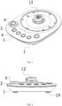
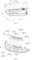
FIG. 1 is a structural schematic diagram of one of the preferred embodiments of the present disclosure; -
FIG. 2 is a schematic side view ofFIG. 1 ; -
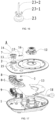
FIG. 3 is a separation schematic diagram of one of the preferred embodiments of the present disclosure; -
FIG. 4 is a schematic structural sectional view of one of the preferred embodiments of the present disclosure; -
FIG. 5 is a partially enlarged schematic diagram at B inFIG. 4 ; -
FIG. 6 is an schematic structural analysis diagram of the bottom structure of a face shell according to one of the preferred embodiments of the present disclosure; -
FIG. 7 is an exploded schematic diagram of the parts inFIG. 5 ; -
FIG. 8 is a combined schematic diagram of the parts inFIG. 5 ; -
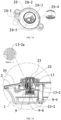
FIG. 9 is a schematic sectional view of a first embodiment of the function knob A according to one embodiment not part of the claimed invention; -
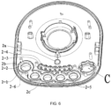
FIG. 10 is a partially enlarged schematic diagram at C inFIG. 6 ; -
FIG. 11 is a schematic structural analysis diagram of a knob inFIG. 9 ; -
FIG. 12 is a schematic structural analysis diagram of a knob transparent aperture inFIG. 9 ; -
FIG. 13 is a schematic sectional view of a second embodiment of the function knob not part of the claimed invention; -
FIG. 14 is a schematic structural analysis diagram of thepart 20 inFIG. 13 ; -
FIG. 15 is a schematic sectional view of a third structural embodiment of a function knob not part of the claimed invention; -
FIG. 16 is a schematic structural analysis diagram of thepart 23 inFIG. 15 ; -
FIG. 17 is a separation schematic diagram of a second preferred embodiment of the present disclosure; -
FIG. 18 is a schematic sectional view of a second preferred embodiment of the present disclosure; -
FIG. 19 is a structural separation schematic diagram of a first embodiment in which thepart 2 and thepart 25 perform mutual secondary injection molding inFIG. 18 ; -
FIG. 20 is a structural separation schematic diagram of a second embodiment in which thepart 2 and thepart 25 perform mutual secondary injection molding inFIG. 18 ; -
FIG. 21 is a structural separation schematic diagram of a third embodiment in which thepart 2 and thepart 25 perform mutual secondary injection molding inFIG. 18 . - The present disclosure will be described in further detail with reference to the accompanying drawings.
- As shown in
FIG. 1 to FIG. 3 , a power supply base with vibration touch keys comprises aface shell 2, abottom cover 1, avibration motor 3, abase connector 12, acontrol circuit board 9, apower cord 18, afoot pad 19, a touch keytransparent aperture 5, a lampstrip progress bar 11 and a knob A. As shown inFIG. 4, FIG. 5 andFIG. 6 , the inner side of theface shell 2 is provided with a slot for installing avibration motor 2a. Avibration motor 3 is installed in the slot. 2a. The vibration surface of thevibration motor 3 is in close contact with the bottom plane of theslot 2a. In order to ensure the reliability of this contact, the vibration surface of thevibration motor 3 is provided with an adhesive layer 3-1 which is tightly bonded with the bottom plane of the installinggroove 2a. The back surface of the vibration motor is pressed by amotor fixing base 801. An elastic buffer material layer 3-2 is provided between thevibration motor 3 and themotor fixing base 801 to protect thevibration motor 3 from crushing and reduce noise. The lead wire 3-3 of thevibration motor 3 is electrically connected with thecontrol circuit board 9. When the finger touches a key, the vibration motor will have synchronous tactile signal feedback, which brings different touch experiences to the user. Theface shell 2 is provided with a touchkey installing hole 2b. A touch keytransparent aperture 5 is installed on the touchkey installing hole 2b. An inner ring of the touch keytransparent aperture 5 is provided with a touchdecorative sheet 4. Afirst sealing ring 6 is provided between the touch keytransparent aperture 5 and theface shell 2. A transparentaperture fixing base 802 is provided below the touch keytransparent aperture 5. The touch keytransparent aperture 5 and the touchdecorative sheet 4 are located above the transparentaperture fixing base 802. The fixing base through hole 8-2 is provided at the middle position of the transparentaperture fixing base 802 corresponding to finger touch, and a touch spring 9-1 on the control circuit board and an indicator lamp 9-2 are installed in the middle of the fixing base through hole 8-2. The touch end of the touch spring 9-1 abuts against with the inner surface of the touch keytransparent aperture 5. The abutting surface 4-3 of the touch keytransparent aperture 5 and the touchdecorative sheet 4 is right at the position of the touch spring 9-1, and no gap is reserved in the design, which is beneficial to touch sensitivity debugging. Theface shell 2 is provided with a lamp strip installing hole 2c. A lampstrip progress bar 11 is installed at the lamp strip installing hole 2c. The lampstrip progress bar 11 consists of a plurality of lamp strip posts 11-1. The bottom end of the lamp strip posts 11-1 is provided with an abutting table 11-4. Asecond sealing ring 10 is provided between the abutting table 11-4 and theface shell 2. A lamp strippost fixing base 803 for fixing the lamp strip post is provided below the lamp strip post 11-1. A lamp strip post through hole 8-3 is provided in the middle of the lamp strip post fixing base 803 corresponding to the lamp strip post 11-1, and a lamp strip indicator lamp 9-3 of the control circuit board is installed in the middle of the lamp strip post through hole 8-3. The function of the lampstrip progress bar 11 is to make cooking say goodbye to blind guessing and make the cooking progress clear at a glance. - As shown in
FIG. 1, FIG. 2 ,FIG. 9 ,FIG. 10, FIG. 11 andFIG. 12 , according to the requirements of product function configuration, a multi-function knob A can be flexibly configured on the touch key-type power cord base. The function knob A mainly consists of aknob 7, a knobtransparent aperture 13, a knobdecorative sheet 14, aknob spring 15 and a slidingpost 16. Theface shell 2 is provided with asecond installing hole 2d for installing theknob 7. A plurality of gear grooves 2-7, a knob abutting surface 2-8, a limiting I bump 2-9 and a limiting II bump 2-10 are provided in thesecond installing hole 2d, as shown inFIG. 10 . Theknob 7 is provided with aknob installing hole 7a, a recess 7-1 and a female buckle 7-2, as shown inFIG. 11 . As shown inFIGS. 9 ,12 and 13 , the knobtransparent aperture 13 comprises a centering shaft 13-1, a potentiometer knob bolt 13-2, an elastic buckle 13-3, a male buckle 13-4, a sealing convex rib 13-5, a limiting convex rib 13-6, an abutting surface convex rib 13-7, an accommodating hole 13-8 and a rotation limiting rib 13-9. As shown inFIG. 9 andFIG. 13 , the knobtransparent aperture 13 is fixed on theknob installing hole 7a. The limiting convex rib 13-6 of the knob transparent aperture coincides with the recess 7-1 of theknob 7, and the male buckle 13-4 of the knobtransparent aperture 13 is buckled with the female buckle 7-2 of theknob 7. One end of the slidingpost 16 is provided with a hollow hole 16-1, and the other end of the slidingpost 16 is provided with a round head 16-1. One end of the slidingpost 16 provided with a hollow hole 16-1 is placed in the accommodating hole 13-8 of the knobtransparent aperture 13, and the hollow hole 16-1 of the slidingpost 16 is sleeved on the centering shaft 13-1 of the knobtransparent aperture 13. Aknob spring 15 is provided between one end of the slidingpost 16 provided with a hollow hole 16-1 and the accommodating hole 13-8 of the knobtransparent aperture 13. The centering shaft 13-1 of the knobtransparent aperture 13 can prevent the slidingpost 16 from being eccentric and crooked, which is beneficial to ensuring the linear expansion and contraction of the slidingpost 16. The function knob A is buckled and connected with the knob abutting surface 2-8 of theface shell 2 by the elastic buckle 13-3 on the knobtransparent aperture 13. - As shown in
FIG. 9 , the potentiometer knob bolt 13-2 of the knobtransparent aperture 13 is inserted into the gear rotary bushing 9-4a of the potentiometer 9-4 on thecontrol circuit board 9. A plurality of indicator lamps 9-5 are provided around the potentiometer 9-4 of the circuit board. The indicator lamps 9-5 are provided between thecontrol circuit board 9 and the knobtransparent aperture 13. A knobdecorative sheet 14 is provided in the inner ring of the knobtransparent aperture 13. The assembly positioning manner of the knobdecorative sheet 14 and the knobtransparent aperture 13 is similar to the structure of the touch keytransparent aperture 5 and the touchdecorative sheet 4. The structure will not be described in detail here. - As shown in
FIG. 9 , the center of thefunction knob 7 has a bolt 13-2 connected to the potentiometer. The slidingpost 16 and theknob spring 15 are installed through the function knob A. Every time thefunction knob 7 rotates to switch an angle, the bolt 13-2 of the potentiometer 9-4 drives the potentiometer gear rotating bushing 9-4a to switch a function angle synchronously, and the slidingpost 16 stretches and bounces into the corresponding gear groove 2-7, thus realizing gear function selection. As shown inFIG. 10 , the gear groove 2-7 consists of a first sliding surface 2-7a and a second sliding surface 2-7b. - In an embodiment, as shown in
FIG. 7 , the touch keytransparent aperture 5 comprises an aperture ring 5-5, a first polygonal positioning hole 5-2, a first positioning rib gap 5-3, a limiting bump 5-4 and a sealing convex rib 5-1. A plurality of touch keytransparent apertures 5 can be connected in series with a connecting arm 5-6 integrally, which is convenient for assembly, quick taking, mistake prevention and foolproof performance. Alternatively, apertures are independent according to structural requirements. A touchdecorative sheet 4 is provided in the inner ring of the touch keytransparent aperture 5. The touchdecorative sheet 4 is provided with a positioning post 4-1, a first positioning rib 4-2 and an abutting surface 4-3. The positioning post 4-1 is provided in the middle of the abutting surface 4-3, and the first positioning rib 4-2 is arranged on the outer surface of the positioning post 4-1 along the axial direction of the positioning post 4-1. The positioning post 4-1 of the touch decorative sheet abuts against the first polygonal positioning hole 5-2 of the touch key transparent aperture. The first positioning rib 4-2 of the touchdecorative sheet 4 is matched with the first positioning rib gap 5-3 of the touch key transparent aperture. The angle of the first positioning rib gap 5-3 is the same as that of the first positioning rib 4-2. According to the needs of functions, the plurality of touch key decorative sheets and the assembly positioning ribs of the transparent apertures can be set differently, so as to play the role of mistake prevention and foolproof performance in assembly. Theface shell 2 is provided with a limiting notch 2-1, a lamp strip limiting notch 2-4, a key silica gel sealing groove 2-2 and a lamp strip silica gel sealing groove 2-3. A touch key transparent aperture limiting bump 5-4 is matched with the limiting notch 2-1 of theface shell 2. - In an embodiment, as shown in
FIG. 6 andFIG. 7 , the lampstrip progress bar 11 comprises a lamp strip post 11-1, a limiting rib 11-2 and a connecting arm 11-3. The limiting rib 11-2 is matched with a lamp strip limiting notch 2-4 on theface shell 2. - In an embodiment, the lights between all the transparent apertures of the present disclosure are designed to prevent light from escaping. As shown in
FIGS. 5 ,6 and7 , theface shell 2 is provided with a key transparent aperture surrounding bone 2-6 and a lamp bar surrounding bone 2-5. The transparentaperture fixing base 802 is provided with a first anti-light escaping surrounding bone 8-4, and the lamp strippost fixing base 803 is provided with a second anti-light escaping surrounding bone 8-5. The touch keytransparent aperture 5 is placed in the first anti-light escaping surrounding bone 8-4. The lamp strip of the lamp strip abutting platform 11-4 is accommodated in the second anti-light escaping surrounding bone 8-5. The first anti-light escaping surrounding bone 8-4 abuts against the key transparent aperture surrounding bone 2-6. The second anti-light escaping surrounding bone 8-5 abuts against the lamp strip surrounding bone 2-5. The surrounding bone is abutted and separated layer by layer for the best anti-light escaping design. The transparentaperture fixing base 802 is provided with a lamp ring avoiding notch 8-1, and the lamp strippost fixing base 803 is provided with a lamp strip avoiding notch 8-6. A lamp ring limiting lug 5-4 corresponding to the lamp strip avoiding notch 8-6 and a lampstrip limiting rib 11 corresponding to the lamp strip avoiding notch 8-6 provide assembly retreating. The position of the avoiding notch key is not opposite to that of the key, and the position of the lamp is not opposite to that of the lamp gap, so as to prevent the light source between gaps from colliding with each other. - In an embodiment, the
motor fixing base 801, the transparentaperture fixing base 802 and the lamp strippost fixing base 803 are combined to form a fixingbase 8. Independent separation in design also falls within the protection scope of this embodiment. - In this embodiment, as shown in
FIG. 8 , the touch key transparentaperture sealing ring 10, the connecting arm 6-2 and the connecting arm 6-3 of the lamp strip progress bar sealing ring are connected integrally, which is convenient for assembly, quick taking, mistake prevention and foolproof performance. Alternatively, the silica gel rings between keys and between lamps are separated from each other, and the lamps are separated from each other's silica gel rings. Without departing from the spirit and scope of this embodiment, independent separation in design also falls within the protection scope of this embodiment. - In an embodiment not part of the claimed invention, as shown in
FIG. 9 , the functional knob A is provided with an annular convex rib 2-11 on theface shell 2. The annular convex rib 2-11 can prevent water droplets from flowing backwards into the knob, and can block water droplets from the knob to avoid circuit damage caused by flowing into the internal circuit board. The abutting mating surface between theknob 7 and the knobtransparent aperture 13 is provided with a waterproof sealing rib 13-5 on the knobtransparent aperture 13. - The installing method of the function knob A is as follows. First, the
knob spring 15 and the slidingpost 16 are installed into the accommodating hole 13-8 of the knob transparent aperture, and simultaneously, the slidingpost 16 is pressed by fingers to be folded into the accommodating hole 13-8. Second, the slidingpost 16 is aligned with the gear groove 2-7. The elastic buckle 13-3 of the knob transparent aperture can stagger the limiting lugs 2-9 and the limiting lugs 2-10 of the face shell. Finally, the elastic buckle 13-3 is buckled into the faceshell installing hole 2d and installed in place. In the buckling process, when the round head 16-1 of the sliding post touches the hole wall of the installinghole 2d, the finger pressing the sliding post is released, and then the function knob A can be installed in place by using the thrust force. After assembly, the slidingpost 16 is restored and bounced into the gear groove 2-7 by the elasticity of theknob spring 15. - In this embodiment, as shown in
FIG. 9 , the slidingpost 16 of the function knob A and the potentiometer bolt 13-2 are arranged vertically, which can be regarded as a first embodiment. The embodiment of the function knob A is not limited to this, and the following second, third and fourth embodiments will be further supplemented. - As shown in
FIG. 13 andFIG. 14 , the structural schematic diagram of a second embodiment not part of the claimed invention of the function knob A in this example is shown. The embodiment is derived from the first embodiment. In the second embodiment of the function knob A, a knobtransparent aperture bracket 20 and a sealingsilica gel ring 21 are added. The slidingpost 16 is placed between the knobtransparent aperture 13 and the knobtransparent aperture bracket 20 and is perpendicular to each other. In this embodiment, the slidingpost 16 and potentiometer bolt 13-2 are arranged side by side, as shown in the figure. In the embodiment, the knobtransparent aperture bracket 20 is provided with a gear groove 20-4, a limiting bump 20-2 and a limiting bump 20-3, a drainage pipe 20-1 and an annular surrounding bone 20-5. A sealingsilica gel ring 21 is provided between the knobtransparent aperture bracket 20 and theface shell 2. The drainage pipe 20-1 is directly connected to the bottom cover water leakage port 1-1, and the annular surrounding bone 20-5 is inserted into the surrounding bone 13-3 and overlapped with each other. The function is to prevent the water droplets entering the knob from flowing backwards, and the entered water droplets can only be discharged out of the line base through the drainage pipe. In this embodiment, the knobtransparent aperture bracket 20 is a transparent member. In this embodiment, simple modifications or improvements made by those skilled in the art, such as changing the gear groove 20-4 to the knob transparent aperture, changing the slidingpost 16 to the knobtransparent aperture bracket 20, and exchanging the position, are considered to be within the protection scope of this embodiment. - As shown in
FIG. 15 andFIG. 16 , the structural schematic diagram of a third embodiment not part of the claimed invention of the function knob A in this embodiment is shown. The third embodiment mainly explains that the knob decorative sheet is changed into a depressible knob key 23 on the basis of the above function knob. The potentiometer bolt 13-2 on the knobtransparent aperture 13 is provided with a through hole 13-2a. Theknob key 23 is provided with a key pin 23-2 and a buckle position 23-1. The key pin 23-2 is placed on the key switch 9-6 through the through hole 13-2a. Theelastic silica gel 22 is provided between theknob key 23 and the knobtransparent aperture 13. Theelastic silica gel 22 plays a role in sealing and resetting the key press. In addition, the surface of theface shell 2 is coated with a layer ofhardware face shell 24, which can improve the product grade. - As shown in
FIG. 17 , it is a separation schematic diagram of parts according to a second embodiment of the present disclosure. As shown inFIG. 18 , it is a schematic structural sectional view of a second embodiment. The difference from the first embodiment ofFIGS. 1 to 8 is that the touch key transparent aperture and the lamp strip progress bar in the described embodiment are secondary injection molding or two-color injection molding process, while thefirst sealing ring 6 and thesecond sealing ring 10 are omitted in this embodiment, theaperture 25 is a primary injection molding part, and theface shell 2 is a secondary injection molding part. As shown inFIG. 19 , it is a structural separation schematic diagram of a first embodiment in which theface shell 2 and thetransparent aperture 25 perform mutual secondary injection molding inFIG. 18 . In the preferred embodiment, thetransparent aperture 25 consists of an aperture 25-1, a glue feeding notch 25-2, a plurality of lamp strip progress bars 25-3, a hole groove 25-4, a first connecting arm 25-5, a second connecting arm 25-6 and a third connecting arm 25-7 integrally. This integrated structure is beneficial to the secondary injection molding and positioning of parts. When choosing the two-color injection molding process, it can reduce the number of molds flowing to hot nozzles, so as to reduce the cost of molds. A touch wall 2-12 filled by secondary injection molding is provided in the inner ring of thetransparent aperture 25. The touch wall 2-12 is injection molded by dipping glue at the position of the glue feeding notch 25-2. The touch wall 2-12 is integrated with theface shell 2 through the dipping glue arm 2-11. The dipping glue arm 2-11 will have shadows when transmitting light. Therefore, the width of the glue feeding notch 25-2 is recommended to be about 1.0mm. On the premise of satisfying the secondary injection molding process, the gap width should be as small as possible. - As shown in
FIG. 18 , in order to avoid light escaping from the lamp source between the transparent aperture 25-1 and the lamp strip progress bar 25-3, the fixingbase 8 is provided with a spacer 8-1 inserted into the hole groove 25-4. Theface shell 2 is provided with a first surrounding bone 2-14 and a second surrounding bone 2-15. The surrounding bone plays a role of light blocking, and its light blocking structure is similar to the first embodiment, which it will not be described in detail here. - As shown in
FIG. 20 , it is a structural separation schematic diagram of a second embodiment in which theface shell 2 and thetransparent aperture 25 perform mutual secondary injection molding inFIG. 18 . The difference from the first embodiment is that the connecting arm 25-6 of thetransparent aperture 25 is provided with an external connection, and the distance between the connecting arm 25-6 and the touch key transparent aperture 25-1 is widened, so that the anti-light escaping effect is better than that of the first embodiment ofFIG. 19 . - As shown in
FIG. 21 , it is a structural separation schematic diagram of a third embodiment in which theface shell 2 and thetransparent aperture 25 perform mutual secondary injection molding inFIG. 18 . The difference from the second embodiment is that thetransparent aperture 25 is independently separated, and the anti-light escaping effect is better than that of the first and second embodiments. - The present disclosure has good waterproof, dustproof, LED light guide, and vibrating effects.
Claims (5)
- A power supply base with vibration touch keys, comprising a face shell (2), a bottom cover (1), a base connector (12), a control circuit board (9) and a power cord (18), wherein the inner side of the face shell (2) is provided with a slot (2a) for installing vibration motor , a vibration motor (3) is installed in the slot (2a), the vibration surface of the vibration motor (3) is in contact with the bottom plane of the slot (2a), the vibration motor (3) is electrically connected with the control circuit board (9), and the vibration motor is configured to have synchronous vibration signal feedback when a finger touches any of the vibration touch keys;
whereinthe face shell (2) is provided with a hole for installing touch key (2b), the hole (2b) is provided with a touch key transparent ring (5), a first sealing ring (6) is provided between the touch key transparent ring (5) and the face shell (2), a transparent ring fixing base (802) for fixing the touch key transparent ring is provided below the touch key transparent ring, the touch key transparent ring (5) is located above the transparent ring fixing base (802), the transparent ring fixing base (802) is provided with a fixing base through hole (8-2) at the middle position corresponding to finger touch, and a touch spring (9-1) on the control circuit board and an indicator lamp (9-2) are installed in the middle of the fixing base through hole (8-2);the face shell (2) is provided with a lamp strip installing hole (2c), a lamp strip progress bar (11) is installed at the lamp strip installing hole (2c), the lamp strip progress bar (11) consists of a plurality of lamp strip posts (11-1), a second sealing ring (10) is provided between the lamp strip progress bar (11) and the face shell (2), a lamp strip post fixing base (803) for fixing the lamp strip post (11-1) is provided below the lamp strip post (11-1), a lamp strip post through hole (8-3) is provided in the middle of the lamp strip post fixing base (803) corresponding to the lamp strip post (11-1), and a lamp strip indicator lamp (9-3) is installed in the lamp strip post through hole (8-3). - The power supply base with vibration touch keys according to claim 1, wherein the touch key transparent ring (5) comprises a ring (5-5), a first polygonal positioning hole (5-2), a first positioning rib gap (5-3), a limiting bump (5-4), a sealing convex rib (5-1), the ring (5-5) is provided with a touch decorative sheet (4), the touch decorative sheet (4) is provided with a touch decorative sheet positioning post (4-1), a first positioning rib (4-2) and an abutting surface (4-3), the touch decorative sheet positioning post (4-1) abuts against a first polygonal positioning hole (5-2) of the transparent ring, and the first positioning rib (4-2) of the touch decorative sheet is matched with the first positioning rib gap (5-3) of the transparent ring; the face shell (2) is provided with a limiting notch (2-1), a lamp strip limiting notch (2-4), a touch key silica gel sealing groove (2-2) and a lamp strip silica gel sealing groove (2-3), and the limiting bump (5-4) of the touch key transparent ring is matched with the limiting notch (2-1) of the face shell (2).
- The power supply base with vibration touch keys according to claim 1, wherein the lamp strip progress bar (11) comprises a lamp strip post (11-1), a limiting rib (11-2), and a connecting arm (11-3), and the limiting rib (11-2) is matched with the lamp strip limiting notch (2-4) on the face shell (2).
- The power supply base with vibration touch keys according to claim 1, wherein: the face shell (2) is provided with a touch key transparent ring surrounding frame (2-6) and a light bar surrounding frame (2-5), the transparent ring fixing base (802) is provided with a first anti-light escaping surrounding frame (8-4), the lamp strip post fixing base (803) is provided with a second anti-light escaping surrounding frame (8-5), the touch key transparent ring (5) is accommodated in the first anti-light escaping surrounding frame (8-4), the lamp strip of a lamp strip abutment table (11-4) is accommodated in the second anti-light escaping surrounding frame (8-5), the first anti-light escaping surrounding frame (8-4) on the transparent ring fixing base (802) abuts against the touch key transparent ring surrounding frame (2-6), the second anti-light escaping surrounding frame (8-5) abuts against the lamp strip surrounding frame (2-5), the transparent ring fixing base (802) is provided with a lamp ring avoiding notch (8-1), the lamp strip post fixing base (803) is provided with a lamp strip avoiding notch (8-6), and a lamp ring limiting lug (5-4) corresponding to the lamp strip avoiding notch (8-6) and a lamp strip limiting rib (11-2) corresponding to the lamp strip avoiding notch (8-6) provide assembly retreating.
- The power supply base with vibration touch keys according to claim 1, wherein the touch key transparent ring sealing ring (10), a first connecting arm (6-2) and a second connecting arm (6-3) of the lamp strip progress strip sealing ring are connected integrally.
Applications Claiming Priority (1)
| Application Number | Priority Date | Filing Date | Title |
|---|---|---|---|
| CN202110063978.2A CN114824875B (en) | 2021-01-18 | 2021-01-18 | Power supply base with vibration sensing touch key |
Publications (3)
| Publication Number | Publication Date |
|---|---|
| EP4029415A2 EP4029415A2 (en) | 2022-07-20 |
| EP4029415A3 EP4029415A3 (en) | 2022-07-27 |
| EP4029415B1 true EP4029415B1 (en) | 2024-12-11 |
Family
ID=78598701
Family Applications (1)
| Application Number | Title | Priority Date | Filing Date |
|---|---|---|---|
| EP21204262.6A Active EP4029415B1 (en) | 2021-01-18 | 2021-10-22 | Power supply base with vibration touch keys |
Country Status (3)
| Country | Link |
|---|---|
| US (1) | US12327960B2 (en) |
| EP (1) | EP4029415B1 (en) |
| CN (1) | CN114824875B (en) |
Families Citing this family (2)
| Publication number | Priority date | Publication date | Assignee | Title |
|---|---|---|---|---|
| JP2025005894A (en) * | 2023-06-28 | 2025-01-17 | パナソニックIpマネジメント株式会社 | Cutting device |
| CN117100567B (en) * | 2023-07-04 | 2025-12-16 | 东莞市多果智创科技有限公司 | Multifunctional massage device |
Citations (3)
| Publication number | Priority date | Publication date | Assignee | Title |
|---|---|---|---|---|
| WO2014016136A1 (en) * | 2012-07-24 | 2014-01-30 | BSH Bosch und Siemens Hausgeräte GmbH | Domestic appliance having a contact surface |
| EP2837721A1 (en) * | 2013-08-13 | 2015-02-18 | Electrolux Appliances Aktiebolag | Laundry appliance provided with a control-panel assembly |
| WO2015149324A1 (en) * | 2014-04-03 | 2015-10-08 | Micro Motion, Inc. | Capacitive touch sensor |
Family Cites Families (35)
| Publication number | Priority date | Publication date | Assignee | Title |
|---|---|---|---|---|
| US860225A (en) * | 1904-01-07 | 1907-07-16 | Monarch Typewriter Co | Type-writing machine. |
| US6027463A (en) * | 1996-12-27 | 2000-02-22 | Moriyasu; Hiro | Music massager |
| DE10352681A1 (en) * | 2003-11-03 | 2005-06-02 | E.G.O. Control Systems Gmbh & Co. Kg | Operating device for operating an electrical appliance with a touch switch |
| KR101022477B1 (en) * | 2004-11-25 | 2011-03-15 | 삼성전자주식회사 | Key input device using magnetic force, its operation method and computer readable recording medium storing computer program |
| US20070142077A1 (en) * | 2005-12-19 | 2007-06-21 | Chiang-Shui Huang | Hand-held device combining controller unit and mobile phone |
| WO2009032598A1 (en) * | 2007-08-29 | 2009-03-12 | Cfph, Llc | Game of chance processing apparatus |
| KR101498622B1 (en) * | 2008-06-25 | 2015-03-04 | 엘지전자 주식회사 | Mobile terminal for providing haptic effect and control method thereof |
| KR101498623B1 (en) * | 2008-06-25 | 2015-03-04 | 엘지전자 주식회사 | A mobile terminal and a control method thereof |
| KR101556522B1 (en) * | 2008-06-27 | 2015-10-01 | 엘지전자 주식회사 | Mobile terminal for providing haptic effect and control method thereof |
| US8169306B2 (en) * | 2009-03-23 | 2012-05-01 | Methode Electronics, Inc. | Touch panel assembly with haptic effects and method of manufacturing thereof |
| KR101672212B1 (en) * | 2010-06-15 | 2016-11-04 | 엘지전자 주식회사 | Mobile terminal and operation method thereof |
| KR101606727B1 (en) * | 2010-06-25 | 2016-03-28 | 엘지전자 주식회사 | Mobile terminal and operation method thereof |
| KR101685363B1 (en) * | 2010-09-27 | 2016-12-12 | 엘지전자 주식회사 | Mobile terminal and operation method thereof |
| EP2446788A1 (en) * | 2010-10-27 | 2012-05-02 | Koninklijke Philips Electronics N.V. | Tea maker with symbol-selectable tea brewing program |
| US20130233685A1 (en) * | 2012-03-06 | 2013-09-12 | Qing Zhang | Press key |
| KR20150066832A (en) * | 2013-12-09 | 2015-06-17 | 삼성전자주식회사 | An electronic device including openable cover |
| US9484631B1 (en) * | 2014-12-01 | 2016-11-01 | Amazon Technologies, Inc. | Split band antenna design |
| CN105167520A (en) * | 2015-03-26 | 2015-12-23 | 深圳市一么么科技有限公司 | Cup base |
| CN205411929U (en) * | 2015-12-10 | 2016-08-03 | 周泉清 | Well low frequency channels and collaterals health preservation massages appearance |
| KR102553886B1 (en) * | 2015-12-24 | 2023-07-11 | 삼성전자주식회사 | Electronic device and method for image control thereof |
| WO2018003266A1 (en) * | 2016-06-28 | 2018-01-04 | 三菱電機株式会社 | Electric rice cooker, household electric appliance, power command device and operation management system for household electric appliance |
| CN206134574U (en) * | 2016-09-29 | 2017-04-26 | 普天智能照明研究院有限公司 | Touch -control flush mounting plate of switch of area vibration feedback |
| KR102729069B1 (en) * | 2016-12-01 | 2024-11-13 | 삼성전자 주식회사 | Lamp device for inputting or outputting voice signals and a method of driving the lamp device |
| KR102663618B1 (en) * | 2017-02-23 | 2024-05-09 | 삼성전자 주식회사 | Multi-band antenna device and electronic device comprising the same |
| KR102387164B1 (en) * | 2017-03-28 | 2022-04-18 | 삼성전자주식회사 | Electronic device and method for controlling audio path thereof |
| DE102017113658A1 (en) * | 2017-06-21 | 2018-12-27 | Trw Automotive Electronics & Components Gmbh | Motor vehicle operating device |
| KR102374408B1 (en) * | 2017-09-08 | 2022-03-15 | 삼성전자주식회사 | Method for controlling a pointer in a screen of virtual reality and electronic device |
| US10754439B2 (en) * | 2018-06-29 | 2020-08-25 | Intel Corporation | Selectively displaced keys for input and output |
| US11199853B1 (en) * | 2018-07-11 | 2021-12-14 | AI Incorporated | Versatile mobile platform |
| CN109039318B (en) * | 2018-07-27 | 2023-01-24 | 惠州市德赛西威汽车电子股份有限公司 | Touch key vibration feedback touch device, control circuit and control method thereof |
| CN211063908U (en) * | 2019-12-30 | 2020-07-21 | 重庆权奇科技有限公司 | Dustproof and waterproof controller suitable for control tarpaulin motor |
| CN215583777U (en) * | 2020-12-31 | 2022-01-21 | 汉华数字饮水器具科技(深圳)有限公司 | Intelligent cup |
| CN214254811U (en) * | 2021-01-18 | 2021-09-21 | 深圳市北鼎科技有限公司 | Power supply seat with vibration sense touch key |
| CN215133291U (en) * | 2021-04-02 | 2021-12-14 | 左点实业(湖北)有限公司 | Intelligent interactive sitting moxibustion instrument |
| CN219578692U (en) * | 2023-02-24 | 2023-08-25 | 广东德琪电器实业有限公司 | Liquid heater |
-
2021
- 2021-01-18 CN CN202110063978.2A patent/CN114824875B/en active Active
- 2021-10-22 EP EP21204262.6A patent/EP4029415B1/en active Active
- 2021-10-22 US US17/507,830 patent/US12327960B2/en active Active
Patent Citations (3)
| Publication number | Priority date | Publication date | Assignee | Title |
|---|---|---|---|---|
| WO2014016136A1 (en) * | 2012-07-24 | 2014-01-30 | BSH Bosch und Siemens Hausgeräte GmbH | Domestic appliance having a contact surface |
| EP2837721A1 (en) * | 2013-08-13 | 2015-02-18 | Electrolux Appliances Aktiebolag | Laundry appliance provided with a control-panel assembly |
| WO2015149324A1 (en) * | 2014-04-03 | 2015-10-08 | Micro Motion, Inc. | Capacitive touch sensor |
Also Published As
| Publication number | Publication date |
|---|---|
| US20220231468A1 (en) | 2022-07-21 |
| CN114824875A (en) | 2022-07-29 |
| CN114824875B (en) | 2024-12-17 |
| EP4029415A3 (en) | 2022-07-27 |
| EP4029415A2 (en) | 2022-07-20 |
| US12327960B2 (en) | 2025-06-10 |
Similar Documents
| Publication | Publication Date | Title |
|---|---|---|
| EP4029415A2 (en) | Power supply socket with vibration touch keys | |
| JP7053258B2 (en) | Bi-directional electric connect socket and bi-directional electric connect plug | |
| US7749001B2 (en) | Computer peripheral device with a movable protective shelter body | |
| EP2337225B1 (en) | Icon illumination for capacitive touch switch | |
| US20070292186A1 (en) | Washable keyboard | |
| GB2497978A (en) | Liquid heating vessel and control | |
| CN214254811U (en) | Power supply seat with vibration sense touch key | |
| CN201111008Y (en) | Bus cable package assembly of touching control panel | |
| CN202651477U (en) | A waterproof socket | |
| CN209694865U (en) | Cooking apparatus | |
| CN209471428U (en) | A kind of mouse of changeable switch | |
| CN204164425U (en) | A kind of automatically controlled hydroseparator structure | |
| CN209357030U (en) | The cover plate assembly of In-cell touch panel | |
| CN217508738U (en) | Display devices and home appliances | |
| CN201282360Y (en) | Modularization case structure of electric load administrative terminal | |
| CN201219827Y (en) | Touching control panel | |
| CN101752746B (en) | RJ45 connector device with button structure to change pin definition | |
| CN215651695U (en) | Touch control type electric toothbrush | |
| CN117638562A (en) | Electric connection module, face lid subassembly and cooking device | |
| CN211744446U (en) | Novel capacitive touch switch | |
| CN206080216U (en) | Independent collision of rice cooker device of uncapping | |
| CN211375469U (en) | A waterproof, dustproof and drop-proof tablet computer and its casing | |
| CN219204996U (en) | Household appliance waterproof control structure and household appliance | |
| CN222749781U (en) | Protective shell of socket and socket | |
| CN206560279U (en) | Cooking utensil |
Legal Events
| Date | Code | Title | Description |
|---|---|---|---|
| PUAI | Public reference made under article 153(3) epc to a published international application that has entered the european phase |
Free format text: ORIGINAL CODE: 0009012 |
|
| STAA | Information on the status of an ep patent application or granted ep patent |
Free format text: STATUS: REQUEST FOR EXAMINATION WAS MADE |
|
| PUAL | Search report despatched |
Free format text: ORIGINAL CODE: 0009013 |
|
| 17P | Request for examination filed |
Effective date: 20211022 |
|
| AK | Designated contracting states |
Kind code of ref document: A2 Designated state(s): AL AT BE BG CH CY CZ DE DK EE ES FI FR GB GR HR HU IE IS IT LI LT LU LV MC MK MT NL NO PL PT RO RS SE SI SK SM TR |
|
| AK | Designated contracting states |
Kind code of ref document: A3 Designated state(s): AL AT BE BG CH CY CZ DE DK EE ES FI FR GB GR HR HU IE IS IT LI LT LU LV MC MK MT NL NO PL PT RO RS SE SI SK SM TR |
|
| RIC1 | Information provided on ipc code assigned before grant |
Ipc: H03K 17/96 20060101ALI20220617BHEP Ipc: A47J 27/21 20060101AFI20220617BHEP |
|
| GRAP | Despatch of communication of intention to grant a patent |
Free format text: ORIGINAL CODE: EPIDOSNIGR1 |
|
| STAA | Information on the status of an ep patent application or granted ep patent |
Free format text: STATUS: GRANT OF PATENT IS INTENDED |
|
| INTG | Intention to grant announced |
Effective date: 20240708 |
|
| GRAS | Grant fee paid |
Free format text: ORIGINAL CODE: EPIDOSNIGR3 |
|
| GRAA | (expected) grant |
Free format text: ORIGINAL CODE: 0009210 |
|
| STAA | Information on the status of an ep patent application or granted ep patent |
Free format text: STATUS: THE PATENT HAS BEEN GRANTED |
|
| AK | Designated contracting states |
Kind code of ref document: B1 Designated state(s): AL AT BE BG CH CY CZ DE DK EE ES FI FR GB GR HR HU IE IS IT LI LT LU LV MC MK MT NL NO PL PT RO RS SE SI SK SM TR |
|
| REG | Reference to a national code |
Ref country code: GB Ref legal event code: FG4D |
|
| REG | Reference to a national code |
Ref country code: CH Ref legal event code: EP |
|
| REG | Reference to a national code |
Ref country code: IE Ref legal event code: FG4D |
|
| REG | Reference to a national code |
Ref country code: DE Ref legal event code: R096 Ref document number: 602021023191 Country of ref document: DE |
|
| REG | Reference to a national code |
Ref country code: LT Ref legal event code: MG9D |
|
| PG25 | Lapsed in a contracting state [announced via postgrant information from national office to epo] |
Ref country code: HR Free format text: LAPSE BECAUSE OF FAILURE TO SUBMIT A TRANSLATION OF THE DESCRIPTION OR TO PAY THE FEE WITHIN THE PRESCRIBED TIME-LIMIT Effective date: 20241211 |
|
| PG25 | Lapsed in a contracting state [announced via postgrant information from national office to epo] |
Ref country code: FI Free format text: LAPSE BECAUSE OF FAILURE TO SUBMIT A TRANSLATION OF THE DESCRIPTION OR TO PAY THE FEE WITHIN THE PRESCRIBED TIME-LIMIT Effective date: 20241211 |
|
| PG25 | Lapsed in a contracting state [announced via postgrant information from national office to epo] |
Ref country code: BG Free format text: LAPSE BECAUSE OF FAILURE TO SUBMIT A TRANSLATION OF THE DESCRIPTION OR TO PAY THE FEE WITHIN THE PRESCRIBED TIME-LIMIT Effective date: 20241211 |
|
| REG | Reference to a national code |
Ref country code: NL Ref legal event code: MP Effective date: 20241211 |
|
| PG25 | Lapsed in a contracting state [announced via postgrant information from national office to epo] |
Ref country code: ES Free format text: LAPSE BECAUSE OF FAILURE TO SUBMIT A TRANSLATION OF THE DESCRIPTION OR TO PAY THE FEE WITHIN THE PRESCRIBED TIME-LIMIT Effective date: 20241211 |
|
| PG25 | Lapsed in a contracting state [announced via postgrant information from national office to epo] |
Ref country code: NO Free format text: LAPSE BECAUSE OF FAILURE TO SUBMIT A TRANSLATION OF THE DESCRIPTION OR TO PAY THE FEE WITHIN THE PRESCRIBED TIME-LIMIT Effective date: 20250311 |
|
| PG25 | Lapsed in a contracting state [announced via postgrant information from national office to epo] |
Ref country code: LV Free format text: LAPSE BECAUSE OF FAILURE TO SUBMIT A TRANSLATION OF THE DESCRIPTION OR TO PAY THE FEE WITHIN THE PRESCRIBED TIME-LIMIT Effective date: 20241211 Ref country code: GR Free format text: LAPSE BECAUSE OF FAILURE TO SUBMIT A TRANSLATION OF THE DESCRIPTION OR TO PAY THE FEE WITHIN THE PRESCRIBED TIME-LIMIT Effective date: 20250312 |
|
| PG25 | Lapsed in a contracting state [announced via postgrant information from national office to epo] |
Ref country code: RS Free format text: LAPSE BECAUSE OF FAILURE TO SUBMIT A TRANSLATION OF THE DESCRIPTION OR TO PAY THE FEE WITHIN THE PRESCRIBED TIME-LIMIT Effective date: 20250311 |
|
| PG25 | Lapsed in a contracting state [announced via postgrant information from national office to epo] |
Ref country code: NL Free format text: LAPSE BECAUSE OF FAILURE TO SUBMIT A TRANSLATION OF THE DESCRIPTION OR TO PAY THE FEE WITHIN THE PRESCRIBED TIME-LIMIT Effective date: 20241211 |
|
| REG | Reference to a national code |
Ref country code: AT Ref legal event code: MK05 Ref document number: 1749658 Country of ref document: AT Kind code of ref document: T Effective date: 20241211 |
|
| PG25 | Lapsed in a contracting state [announced via postgrant information from national office to epo] |
Ref country code: SM Free format text: LAPSE BECAUSE OF FAILURE TO SUBMIT A TRANSLATION OF THE DESCRIPTION OR TO PAY THE FEE WITHIN THE PRESCRIBED TIME-LIMIT Effective date: 20241211 |
|
| PG25 | Lapsed in a contracting state [announced via postgrant information from national office to epo] |
Ref country code: PL Free format text: LAPSE BECAUSE OF FAILURE TO SUBMIT A TRANSLATION OF THE DESCRIPTION OR TO PAY THE FEE WITHIN THE PRESCRIBED TIME-LIMIT Effective date: 20241211 |
|
| PG25 | Lapsed in a contracting state [announced via postgrant information from national office to epo] |
Ref country code: IS Free format text: LAPSE BECAUSE OF FAILURE TO SUBMIT A TRANSLATION OF THE DESCRIPTION OR TO PAY THE FEE WITHIN THE PRESCRIBED TIME-LIMIT Effective date: 20250411 |
|
| PG25 | Lapsed in a contracting state [announced via postgrant information from national office to epo] |
Ref country code: PT Free format text: LAPSE BECAUSE OF FAILURE TO SUBMIT A TRANSLATION OF THE DESCRIPTION OR TO PAY THE FEE WITHIN THE PRESCRIBED TIME-LIMIT Effective date: 20250411 |
|
| PG25 | Lapsed in a contracting state [announced via postgrant information from national office to epo] |
Ref country code: EE Free format text: LAPSE BECAUSE OF FAILURE TO SUBMIT A TRANSLATION OF THE DESCRIPTION OR TO PAY THE FEE WITHIN THE PRESCRIBED TIME-LIMIT Effective date: 20241211 |
|
| PG25 | Lapsed in a contracting state [announced via postgrant information from national office to epo] |
Ref country code: AT Free format text: LAPSE BECAUSE OF FAILURE TO SUBMIT A TRANSLATION OF THE DESCRIPTION OR TO PAY THE FEE WITHIN THE PRESCRIBED TIME-LIMIT Effective date: 20241211 Ref country code: RO Free format text: LAPSE BECAUSE OF FAILURE TO SUBMIT A TRANSLATION OF THE DESCRIPTION OR TO PAY THE FEE WITHIN THE PRESCRIBED TIME-LIMIT Effective date: 20241211 |
|
| PG25 | Lapsed in a contracting state [announced via postgrant information from national office to epo] |
Ref country code: SK Free format text: LAPSE BECAUSE OF FAILURE TO SUBMIT A TRANSLATION OF THE DESCRIPTION OR TO PAY THE FEE WITHIN THE PRESCRIBED TIME-LIMIT Effective date: 20241211 |
|
| PG25 | Lapsed in a contracting state [announced via postgrant information from national office to epo] |
Ref country code: CZ Free format text: LAPSE BECAUSE OF FAILURE TO SUBMIT A TRANSLATION OF THE DESCRIPTION OR TO PAY THE FEE WITHIN THE PRESCRIBED TIME-LIMIT Effective date: 20241211 |
|
| PG25 | Lapsed in a contracting state [announced via postgrant information from national office to epo] |
Ref country code: IT Free format text: LAPSE BECAUSE OF FAILURE TO SUBMIT A TRANSLATION OF THE DESCRIPTION OR TO PAY THE FEE WITHIN THE PRESCRIBED TIME-LIMIT Effective date: 20241211 |
|
| PG25 | Lapsed in a contracting state [announced via postgrant information from national office to epo] |
Ref country code: SE Free format text: LAPSE BECAUSE OF FAILURE TO SUBMIT A TRANSLATION OF THE DESCRIPTION OR TO PAY THE FEE WITHIN THE PRESCRIBED TIME-LIMIT Effective date: 20241211 |
|
| REG | Reference to a national code |
Ref country code: DE Ref legal event code: R097 Ref document number: 602021023191 Country of ref document: DE |
|
| PG25 | Lapsed in a contracting state [announced via postgrant information from national office to epo] |
Ref country code: DK Free format text: LAPSE BECAUSE OF FAILURE TO SUBMIT A TRANSLATION OF THE DESCRIPTION OR TO PAY THE FEE WITHIN THE PRESCRIBED TIME-LIMIT Effective date: 20241211 |
|
| PGFP | Annual fee paid to national office [announced via postgrant information from national office to epo] |
Ref country code: GB Payment date: 20250924 Year of fee payment: 5 |
|
| PLBE | No opposition filed within time limit |
Free format text: ORIGINAL CODE: 0009261 |
|
| STAA | Information on the status of an ep patent application or granted ep patent |
Free format text: STATUS: NO OPPOSITION FILED WITHIN TIME LIMIT |
|
| 26N | No opposition filed |
Effective date: 20250912 |
|
| PGFP | Annual fee paid to national office [announced via postgrant information from national office to epo] |
Ref country code: DE Payment date: 20251015 Year of fee payment: 5 |
|
| PGFP | Annual fee paid to national office [announced via postgrant information from national office to epo] |
Ref country code: FR Payment date: 20251027 Year of fee payment: 5 |