EP4029359A1 - Front lower links system for super steer agricultural vehicle and super steer agricultural vehicle including the front lower links system - Google Patents
Front lower links system for super steer agricultural vehicle and super steer agricultural vehicle including the front lower links system Download PDFInfo
- Publication number
- EP4029359A1 EP4029359A1 EP22152301.2A EP22152301A EP4029359A1 EP 4029359 A1 EP4029359 A1 EP 4029359A1 EP 22152301 A EP22152301 A EP 22152301A EP 4029359 A1 EP4029359 A1 EP 4029359A1
- Authority
- EP
- European Patent Office
- Prior art keywords
- support
- arm
- arms
- frame
- super
- Prior art date
- Legal status (The legal status is an assumption and is not a legal conclusion. Google has not performed a legal analysis and makes no representation as to the accuracy of the status listed.)
- Granted
Links
Images

Classifications
-
- A—HUMAN NECESSITIES
- A01—AGRICULTURE; FORESTRY; ANIMAL HUSBANDRY; HUNTING; TRAPPING; FISHING
- A01B—SOIL WORKING IN AGRICULTURE OR FORESTRY; PARTS, DETAILS, OR ACCESSORIES OF AGRICULTURAL MACHINES OR IMPLEMENTS, IN GENERAL
- A01B59/00—Devices specially adapted for connection between animals or tractors and agricultural machines or implements
- A01B59/002—Details, component parts
- A01B59/004—Length-adjustable links
-
- A—HUMAN NECESSITIES
- A01—AGRICULTURE; FORESTRY; ANIMAL HUSBANDRY; HUNTING; TRAPPING; FISHING
- A01B—SOIL WORKING IN AGRICULTURE OR FORESTRY; PARTS, DETAILS, OR ACCESSORIES OF AGRICULTURAL MACHINES OR IMPLEMENTS, IN GENERAL
- A01B59/00—Devices specially adapted for connection between animals or tractors and agricultural machines or implements
- A01B59/06—Devices specially adapted for connection between animals or tractors and agricultural machines or implements for machines mounted on tractors
- A01B59/064—Devices specially adapted for connection between animals or tractors and agricultural machines or implements for machines mounted on tractors for connection to the front of the tractor
-
- A—HUMAN NECESSITIES
- A01—AGRICULTURE; FORESTRY; ANIMAL HUSBANDRY; HUNTING; TRAPPING; FISHING
- A01B—SOIL WORKING IN AGRICULTURE OR FORESTRY; PARTS, DETAILS, OR ACCESSORIES OF AGRICULTURAL MACHINES OR IMPLEMENTS, IN GENERAL
- A01B71/00—Construction or arrangement of setting or adjusting mechanisms, of implement or tool drive or of power take-off; Means for protecting parts against dust, or the like; Adapting machine elements to or for agricultural purposes
- A01B71/06—Special adaptations of coupling means between power take-off and transmission shaft to the implement or machine
Definitions
- the present invention relates to the field of the interfaces of agricultural super steer vehicles needed to connect an appliance or implement to the front of the vehicle.
- the super steer vehicle are special agricultural vehicles where the entire front axle rotate over a central hinge.
- this kind of steering solution differs from the usual solutions where each front wheel is provided with a hinge.
- the main advantage of the super steer vehicles is the reduced steering angle, so that such vehicles are capable to turn almost on itself. This feature is particularly appreciated at the end of crop rows, when the vehicle has to turn to work further crop rows.
- the super steer vehicles are capable to carry front appliances or implements, active or passive.
- Active means that the implement receives the motion from the front PTO, while passive means that the implements is not driven by the vehicle engine, but simply suspended to the front portion of the vehicle.
- Front Hitch Power Lift In order to attach such appliances to the front of the vehicle is provided of the so called Front Hitch Power Lift (FHPL), which includes two hinged and paired arms with an hook at the free end of each arm and a couple of hydraulic actuator suitable to raise/lower the arms.
- FHPL Front Hitch Power Lift
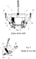
- Figures 1 and 2 disclose an example of FHPL of the prior art, according to a frontal view and a corresponding lateral view of the example.
- a frame F defines a structure to which hydraulic actuators 13 and 23 and the swinging support 3 are hinged.
- the swinging support 3 supports the arms 11 and 21 and has a first portion hinged to the frame F and a second portion, opposite to the first one, arranged to support the arms 11 and 21.
- the first portion, hinged to the frame defines a hinge axis HI.
- the hydraulic actuators 13 and 23 are hinged on one end to the frame defining the hinge axis H2, and on the opposite end, to the support 3 defining the hinge axis H3.
- the hydraulic actuator motion causes the rotation of the support 3 over the first hinge axis HI.
- the two hydraulic actuators are parallel between each other and work constantly at the same manner to rise and lower the support 3 and its arms consequently.
- the arms are often interchangeable in order for better adapting to the kind of appliance, especially in case of active appliance for optimizing its connection to the PTO.
- the arms 12 and 13 are connected to the support 3 by means of a couple of pins P. More in particular the support 3 comprises two forks housing where the arms are inserted and the pins P are inserted transversally in order to lock each arm to the corresponding housing.
- the main principle of the invention is render the extension of the arm adjustable without replacing them through a telescopic configuration.
- the support element includes tubular housings, one for each of the arms, such that the arms can be locked though pins in at least two configurations: extracted and retracted.
- each pair of arms has not only its length but also its diverging shape in order to fit the kind of implement to be hooked. Therefore, in case of diverging tubular housings, the distance between the hooks would change according to the extraction/retraction movement of the arms with respect to the respective housings.
- tubular housings are reciprocally parallel such that the extraction/retraction of the arms would not affect the distance between the hooks.
- the arms are curved and the hooks are slidably associated to the arms such that it is possible to adapt the distance between the hooks to receive a specific appliance.
- the arms are L-shaped, such that the free ends of the arms are reciprocally diverging or converging.
- the distance between the hooks and the extension of the arms are independent conditions between each other, therefore, it is possible to grasp any kind of appliance and to maintain it in at least two conditions: retracted/extracted.
- second element does not imply the presence of a "first element”, first, second, etc.. are used only for improving the clarity of the description and they should not be interpreted in a limiting way.
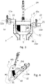
- the FHPL of the present invention differs from prior art essentially for the support 3, which includes a first portion 31, directly hinged to the frame F, and a second portion 32 including tubular housings arranged to receive the arms 2 in a telescopic fashion.
- the support 3 defines an (inverted) A-shape with the tubular housings arranged parallel between each other, while the first portion 31 includes two diverging elements and a traverse T connecting the two diverging elements.
- the traverse is disposed at the interconnection between the diverging elements and the tubular housings.
- the first hinge axis H1 defines the section where the diversion of the two diverging elements starts.
- the support 3 is symmetric with respect to a vertical plane including the longitudinal axis X of the vehicle.
- Each tubular housing has an inner shape such that to receive the corresponding arm 11, 21 by permitting only a simple sliding movement with a limited the reciprocal play.
- the inner shape of the tubular housing is parallelepiped as at least a corresponding portion of the arm 11, 21.
- the arms are supported in a telescopic fashion by the support 3.
- the first portion 31 of the support 3 appears to be inclined with the concavity facing forward. This shape permits to limit the height of the FHPL and to guarantee a good clearance of the vehicle from the ground.
- the locking system for locking a reciprocal position between an arm and its housing includes at least one pin PN, suitable to fit a passing through opening PH defined by both the tubular housing and the corresponding arm.
- the opening PH is arranged transversally to the reciprocal sliding motion of the arm with respect to the corresponding housing.
- the same pin(s) PN is used to lock the arm in all the admitted operative positions between the fully extracted and fully retracted operative positions.
- an operative configuration refers to the arm fixedly connected to the support 3.
- the pin in turn, includes a cotter pin CPN suitable to avoid any unwanted extraction of the pin from the corresponding opening.
- the cotter pin is provided of a rotatable hinged ring suitable to be folded on the end of the pin by locking the cotter pin in its seat.
- each arm has a certain number of passing through openings such that to be locked over the corresponding tubular housing in at least two different extraction conditions, such that to define a retracted and an extracted condition.
- the left arm 11 is disclosed in extracted condition, while the right arm 21 is disclosed in retracted condition, to compare the at least two different configurations.
- the arms 11 and 21 are L-shaped, according to a preferred embodiment of the invention, and the corresponding hooks 12, 22 are not fixed with the arms as for the prior art, but can be associated to each corresponding arms at different positions in order to vary the distance between the hooks.
- each hook is affixed on a tubular element 12a, 22a having a symmetry axis perpendicular to the plane including the body of the hook, such that the tubular element can fit the end 11b, 21b of the corresponding arms 11 and 21.
- connection between each hook and the corresponding arm is realized in a slidably fashion.
- the arms are shaped in both cases, as the male of the coupling with the support 3 and with the hooks 12, 22, which is considered to represent the better solution; however, it could be conceived also a mechanical inversion, where the arms define tubular housings and the support 3 and/or the hooks 12, 22 include a longitudinal element suitable to fit into tubular housings of the arms.
- the hooks are provided of a lock system for locking the reciprocal position of each hook over the corresponding arm. Also in this case, it is preferable to implement a pin PN as those used to lock the reciprocal position of the arms with respect to the support 3.
- Figure 5 disclose a frontal-bottom view of the FHPL similar to figure 3 , where the arms develop the same extension. Also in this case the hooks are disclosed in asymmetric positions only to clarify that their position is not fixed.
- the arms are L-shaped and can be coupled with the corresponding tubular housings with the ends 11b and 21b diverging as disclosed in all the figures 3 - 6 .
- the L-shaped arms can be exchanged such that the ends are converging. In other words the left arm is put on the right and the right arm is put on the left.
- Such solution can be useful in accordance with the features of the appliance to be attached to the vehicle.
- the 90° L-shape is only optional. Indeed the angle between the two portions of each arm can be larger than 90°. It is clear that the hooks tubular elements 12a, 22a should be inclined with respect to the hook body in such a way to slide over the arms by keeping the hooks body lying in a vertical plane parallel with the longitudinal development X of the vehicle. Therefore, the bend of each arm and the bend of the corresponding hook are reciprocal complimentary.
- the FHPL of the present invention includes at least an actuator 23 to obtain the raising lowering of the arms with respect to the frame F.
- the FHPL of the present invention includes an upper arm UA hinged on the top portion of the frame such that the relating hinge axis is parallel with the first hinge axis H1, relating to the support 3.
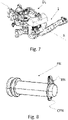
- Figure 7 discloses the front transmission DL of the agricultural vehicle with the FHPL of the present invention. It shows the links to connect and drive in rotation one of the front wheels.
- the transmission DL is hinged to the rest of the vehicle (no disclosed) in such a way to rotate around a vertical axis in a known way, so the entire front axle rather than the sole wheels rotates.
- Example embodiments are provided so that this disclosure will be thorough, and will fully convey the scope to those who are skilled in the art. Numerous specific details are set forth such as examples of specific components, devices, and methods, to provide a thorough understanding of embodiments of the present disclosure. It will be apparent to those skilled in the art that specific details need not be employed, that example embodiments may be embodied in many different forms and that neither should be construed to limit the scope of the disclosure. In some example embodiments, well known processes, well-known device structures, and well known technologies are not described in detail.
Landscapes
- Life Sciences & Earth Sciences (AREA)
- Zoology (AREA)
- Engineering & Computer Science (AREA)
- Mechanical Engineering (AREA)
- Soil Sciences (AREA)
- Environmental Sciences (AREA)
- Body Structure For Vehicles (AREA)
- Agricultural Machines (AREA)
- Steering-Linkage Mechanisms And Four-Wheel Steering (AREA)
- Guiding Agricultural Machines (AREA)
Abstract
Description
- The present invention relates to the field of the interfaces of agricultural super steer vehicles needed to connect an appliance or implement to the front of the vehicle.
- The super steer vehicle are special agricultural vehicles where the entire front axle rotate over a central hinge.
- Therefore, this kind of steering solution differs from the usual solutions where each front wheel is provided with a hinge. The main advantage of the super steer vehicles is the reduced steering angle, so that such vehicles are capable to turn almost on itself. This feature is particularly appreciated at the end of crop rows, when the vehicle has to turn to work further crop rows.
- Often the super steer vehicles are capable to carry front appliances or implements, active or passive.
- "Active" means that the implement receives the motion from the front PTO, while passive means that the implements is not driven by the vehicle engine, but simply suspended to the front portion of the vehicle.
- In order to attach such appliances to the front of the vehicle is provided of the so called Front Hitch Power Lift (FHPL), which includes two hinged and paired arms with an hook at the free end of each arm and a couple of hydraulic actuator suitable to raise/lower the arms.
-
Figures 1 and 2 disclose an example of FHPL of the prior art, according to a frontal view and a corresponding lateral view of the example. - A frame F defines a structure to which
hydraulic actuators swinging support 3 are hinged. Theswinging support 3 supports thearms arms hydraulic actuators support 3 defining the hinge axis H3. - The hydraulic actuator motion causes the rotation of the
support 3 over the first hinge axis HI. - As clear from
figure 1 , the two hydraulic actuators are parallel between each other and work constantly at the same manner to rise and lower thesupport 3 and its arms consequently. - The arms are often interchangeable in order for better adapting to the kind of appliance, especially in case of active appliance for optimizing its connection to the PTO. The
arms support 3 by means of a couple of pins P. More in particular thesupport 3 comprises two forks housing where the arms are inserted and the pins P are inserted transversally in order to lock each arm to the corresponding housing. - However, when a pair of arms is in use, another pair must be stored till a new need. Storing the not-in-use arms is inconvenient.
- Therefore, it is the main object of the present invention to provide front lower links system for super steer agricultural vehicle, which overcomes the above problems/drawbacks.
- The main principle of the invention is render the extension of the arm adjustable without replacing them through a telescopic configuration. In particular, the support element includes tubular housings, one for each of the arms, such that the arms can be locked though pins in at least two configurations: extracted and retracted.
- It should be clear that, according to prior art, each pair of arms has not only its length but also its diverging shape in order to fit the kind of implement to be hooked. Therefore, in case of diverging tubular housings, the distance between the hooks would change according to the extraction/retraction movement of the arms with respect to the respective housings.
- Preferably, the tubular housings are reciprocally parallel such that the extraction/retraction of the arms would not affect the distance between the hooks.
- According to another embodiment of the invention, the arms are curved and the hooks are slidably associated to the arms such that it is possible to adapt the distance between the hooks to receive a specific appliance.
- Preferably, the arms are L-shaped, such that the free ends of the arms are reciprocally diverging or converging. Advantageously, the distance between the hooks and the extension of the arms are independent conditions between each other, therefore, it is possible to grasp any kind of appliance and to maintain it in at least two conditions: retracted/extracted.
- These and further objects are achieved by means of the attached claims, which describe preferred embodiments of the invention, forming an integral part of the present description.
- The invention will become fully clear from the following detailed description, given by way of a mere exemplifying and non limiting example, to be read with reference to the attached drawing figures, wherein:
-
Figs. 1 and 2 show respectively a front and a lateral view of known FHPL system, -
Figs. 3 and 4 disclose respectively a front and lateral view of a preferred FHPL according to the present invention; -
Fig. 5 shows front from bottom view of the same preferred FHPL offigures 3 and 4 , -
Fig. 6 shows another perspective view of the example of the previousfigures 3 - 5 , -
Fig. 7 shows the front transmission of a super steer vehicle to which the FHPL is connected forming one piece, -
Fig. 8 discloses a preferred pin implemented to lock slidably portions of the FHPL of the previousfigures 3 - 7 . - The same reference numerals and letters in the figures designate the same or functionally equivalent parts.
- In order to improve the understanding of the invention, the same reference numeral are used of similar components both for prior art and the example of the present invention. According to the present invention, the term "second element" does not imply the presence of a "first element", first, second, etc.. are used only for improving the clarity of the description and they should not be interpreted in a limiting way.
- According to
figures 3 - 5 , the FHPL of the present invention differs from prior art essentially for thesupport 3, which includes afirst portion 31, directly hinged to the frame F, and asecond portion 32 including tubular housings arranged to receive the arms 2 in a telescopic fashion. Preferably, thesupport 3 defines an (inverted) A-shape with the tubular housings arranged parallel between each other, while thefirst portion 31 includes two diverging elements and a traverse T connecting the two diverging elements. The traverse is disposed at the interconnection between the diverging elements and the tubular housings. The first hinge axis H1 defines the section where the diversion of the two diverging elements starts. - It should be noted that, considering
figure 3 , thesupport 3 is symmetric with respect to a vertical plane including the longitudinal axis X of the vehicle. - Each tubular housing has an inner shape such that to receive the
corresponding arm arm - In other words, the arms are supported in a telescopic fashion by the
support 3. - According to
figure 4 , thefirst portion 31 of thesupport 3 appears to be inclined with the concavity facing forward. This shape permits to limit the height of the FHPL and to guarantee a good clearance of the vehicle from the ground. The locking system for locking a reciprocal position between an arm and its housing includes at least one pin PN, suitable to fit a passing through opening PH defined by both the tubular housing and the corresponding arm. - The opening PH is arranged transversally to the reciprocal sliding motion of the arm with respect to the corresponding housing.
- The same pin(s) PN is used to lock the arm in all the admitted operative positions between the fully extracted and fully retracted operative positions.
- An example of PIN is given on
figure 8 . - Of course, the arms can be completely extracted by the
support 3 for replacing them; however, in such case it does not represent an "operative" configuration. According to the present description an operative configuration refers to the arm fixedly connected to thesupport 3. - The pin, in turn, includes a cotter pin CPN suitable to avoid any unwanted extraction of the pin from the corresponding opening. The cotter pin is provided of a rotatable hinged ring suitable to be folded on the end of the pin by locking the cotter pin in its seat.
- According to the present invention, each arm has a certain number of passing through openings such that to be locked over the corresponding tubular housing in at least two different extraction conditions, such that to define a retracted and an extracted condition.
- According to
figure 3 , theleft arm 11 is disclosed in extracted condition, while theright arm 21 is disclosed in retracted condition, to compare the at least two different configurations. - It should be noted that the
arms - Preferably, each hook is affixed on a
tubular element end arms - In other words, also the connection between each hook and the corresponding arm is realized in a slidably fashion.
- It should be noted that the arms are shaped in both cases, as the male of the coupling with the
support 3 and with thehooks support 3 and/or thehooks support 3. -
Figure 5 disclose a frontal-bottom view of the FHPL similar tofigure 3 , where the arms develop the same extension. Also in this case the hooks are disclosed in asymmetric positions only to clarify that their position is not fixed. - The arms are L-shaped and can be coupled with the corresponding tubular housings with the
ends figures 3 - 6 . However, the L-shaped arms can be exchanged such that the ends are converging. In other words the left arm is put on the right and the right arm is put on the left. Such solution can be useful in accordance with the features of the appliance to be attached to the vehicle. - It should be understood that the 90° L-shape is only optional. Indeed the angle between the two portions of each arm can be larger than 90°. It is clear that the hooks
tubular elements - The FHPL of the present invention, as for prior art, includes at least an actuator 23 to obtain the raising lowering of the arms with respect to the frame F.
- As for prior art, the FHPL of the present invention includes an upper arm UA hinged on the top portion of the frame such that the relating hinge axis is parallel with the first hinge axis H1, relating to the
support 3. -
Figure 7 discloses the front transmission DL of the agricultural vehicle with the FHPL of the present invention. It shows the links to connect and drive in rotation one of the front wheels. - The transmission DL is hinged to the rest of the vehicle (no disclosed) in such a way to rotate around a vertical axis in a known way, so the entire front axle rather than the sole wheels rotates.
- Example embodiments are provided so that this disclosure will be thorough, and will fully convey the scope to those who are skilled in the art. Numerous specific details are set forth such as examples of specific components, devices, and methods, to provide a thorough understanding of embodiments of the present disclosure. It will be apparent to those skilled in the art that specific details need not be employed, that example embodiments may be embodied in many different forms and that neither should be construed to limit the scope of the disclosure. In some example embodiments, well known processes, well-known device structures, and well known technologies are not described in detail.
- Many changes, modifications, variations and other uses and applications of the subject invention will become apparent to those skilled in the art after considering the specification and the accompanying drawings which disclose preferred embodiments thereof as described in the appended claims.
- The features disclosed in the prior art background are introduced only in order to better understand the invention and not as a declaration about the existence of known prior art. In addition, said features define the context of the present invention, thus such features shall be considered in common with the detailed description.
- Further implementation details will not be described, as the man skilled in the art is able to carry out the invention starting from the teaching of the above description.
Claims (10)
- Front lower links system (1) for super steer agricultural vehicle including a frame (F), a support (3) hinged to the frame and at least an actuator (23) interposed between the support and the frame to adjust an angular position of the support (3) with respect to the frame (F), the support being arranged to support two arms (11, 12) provided of relating hooks (12, 22), the device being characterized in that the arms extension is adjustable in such a way to define at least an operative extracted configuration and an operative retracted configuration of the arms.
- Device according to claim 1, wherein each arm has ha free end provided with a hook (12, 22), wherein the distance between the hooks is adjustable defining at least two operative conditions.
- Device according to any one of previous claims, wherein the connection between each arm and the support (3) is realized in a telescopic fashion.
- Device according to any one of previous claims, wherein the connection between each arm and the corresponding hook is realized in a telescopic fashion.
- Device according to any one of the previous claims, wherein a stable locking between each arm and the support (3) is realized by means of at least a pin (PN) to be inserted into a passing through opening, passing through the arm and a corresponding housing of the support, such as to lock any reciprocal movement.
- Device according to any one of the previous claims 2-5, wherein a stable locking between each arm and corresponding hook is realized by means of at least a pin (P) to be inserted into a passing through opening, passing through the arm and a corresponding portion (12a, 22a) of the hook, such as to lock any reciprocal movement.
- Device according to any one of preceding claims, wherein the support (3) is A-shaped with a first portion (31) directly hinged to the frame (F) including two diverging elements and two tubular housings (32) connected to the diverging element and a traverse (T) with the opposite ends connected at the interconnection between each diverging element and the tubular housing (32) .
- Device according to any one of the preceding claims 2 - 7, wherein the adjustable movement of each arm is perpendicular to the adjustable movement of each corresponding hook in order to permit independent adjustment of arm length from hooks reciprocal distance.
- Device according to claim 8, wherein each arm is L-shaped, with a first portion (21a) arranged to fit a corresponding support housing and a second portion (21b) arranged to fit a sleeve portion (22a) of the corresponding hook (22).
- Super steer agricultural vehicle including a front lower links system according to any one of the previous claims 1 - 9.
Applications Claiming Priority (1)
| Application Number | Priority Date | Filing Date | Title |
|---|---|---|---|
| IT102021000000845A IT202100000845A1 (en) | 2021-01-19 | 2021-01-19 | FRONT LOWER LINK SYSTEM FOR SUPER STEERING AGRICULTURAL VEHICLES AND SUPER STEER AGRICULTURAL VEHICLES INCLUDING FRONT LOWER LINK SYSTEM |
Publications (2)
| Publication Number | Publication Date |
|---|---|
| EP4029359A1 true EP4029359A1 (en) | 2022-07-20 |
| EP4029359B1 EP4029359B1 (en) | 2025-03-26 |
Family
ID=74875250
Family Applications (1)
| Application Number | Title | Priority Date | Filing Date |
|---|---|---|---|
| EP22152301.2A Active EP4029359B1 (en) | 2021-01-19 | 2022-01-19 | Front lower links system for super steer agricultural vehicle and super steer agricultural vehicle including the front lower links system |
Country Status (2)
| Country | Link |
|---|---|
| EP (1) | EP4029359B1 (en) |
| IT (1) | IT202100000845A1 (en) |
Cited By (1)
| Publication number | Priority date | Publication date | Assignee | Title |
|---|---|---|---|---|
| EP4344522A1 (en) * | 2022-09-30 | 2024-04-03 | Deere & Company | Hitch for a vehicle |
Citations (3)
| Publication number | Priority date | Publication date | Assignee | Title |
|---|---|---|---|---|
| US20090084566A1 (en) * | 2007-09-28 | 2009-04-02 | Gerd Bernhardt | Hitch device for a working vehicle |
| EP3386287B1 (en) * | 2015-12-07 | 2021-01-06 | Multihog R&D Limited | A work vehicle |
| WO2021146615A1 (en) * | 2020-01-15 | 2021-07-22 | Great Plains Manufacturing, Inc. | Autonomous agricultural system |
-
2021
- 2021-01-19 IT IT102021000000845A patent/IT202100000845A1/en unknown
-
2022
- 2022-01-19 EP EP22152301.2A patent/EP4029359B1/en active Active
Patent Citations (3)
| Publication number | Priority date | Publication date | Assignee | Title |
|---|---|---|---|---|
| US20090084566A1 (en) * | 2007-09-28 | 2009-04-02 | Gerd Bernhardt | Hitch device for a working vehicle |
| EP3386287B1 (en) * | 2015-12-07 | 2021-01-06 | Multihog R&D Limited | A work vehicle |
| WO2021146615A1 (en) * | 2020-01-15 | 2021-07-22 | Great Plains Manufacturing, Inc. | Autonomous agricultural system |
Cited By (2)
| Publication number | Priority date | Publication date | Assignee | Title |
|---|---|---|---|---|
| EP4344522A1 (en) * | 2022-09-30 | 2024-04-03 | Deere & Company | Hitch for a vehicle |
| US12653082B2 (en) | 2022-09-30 | 2026-06-16 | Deere & Company | Hitch for a vehicle |
Also Published As
| Publication number | Publication date |
|---|---|
| IT202100000845A1 (en) | 2022-07-19 |
| EP4029359B1 (en) | 2025-03-26 |
Similar Documents
| Publication | Publication Date | Title |
|---|---|---|
| EP1269816B1 (en) | Device for attaching farm implements to a tractor | |
| US20130233580A1 (en) | Smooth forward folding implement frame | |
| US8496070B2 (en) | Folding hitch lift arm | |
| EP4029359B1 (en) | Front lower links system for super steer agricultural vehicle and super steer agricultural vehicle including the front lower links system | |
| SE505020C2 (en) | Side support for lower link arm to three-point bracket | |
| US9468138B2 (en) | Implement for a tractor hitch | |
| CA2749704C (en) | Three-point linkage systems | |
| US20150097362A1 (en) | Tractor counterweight mounting | |
| EP1529430B1 (en) | Device at a soil tillage implement | |
| US9554500B2 (en) | Gravitational latch for wing lift wheels | |
| CN203072317U (en) | Automatic depth wheel of mounted turnover plow | |
| CN111096111B (en) | Power lifting device for agricultural tractor | |
| US3995411A (en) | Oscillating mounting support for agricultural instrument | |
| EP1016340A2 (en) | Automatic device for all-purpose coupling of agricultural implements and the like | |
| CN202773258U (en) | Semi-hanging turnable plow | |
| US12538858B2 (en) | Service hitch attachment | |
| IT202100000878A1 (en) | FRONT LOWER LINK SYSTEM FOR SUPER STEERING AGRICULTURAL VEHICLES AND SUPER STEER AGRICULTURAL VEHICLES INCLUDING FRONT LOWER LINK SYSTEM | |
| CN222339974U (en) | Folding frame of folding returning machine | |
| RU26873U1 (en) | TRACTOR ATTACHMENT | |
| EP4117411B1 (en) | Improved pick-up hitch assembly | |
| RU2322779C2 (en) | Loader for farm tractors | |
| CN216437977U (en) | Suspension type hydraulic side-moving mower | |
| US2969602A (en) | Tractor lift | |
| WO2025094160A1 (en) | Plough | |
| JP3001898B2 (en) | Tractor work equipment coupling device |
Legal Events
| Date | Code | Title | Description |
|---|---|---|---|
| PUAI | Public reference made under article 153(3) epc to a published international application that has entered the european phase |
Free format text: ORIGINAL CODE: 0009012 |
|
| STAA | Information on the status of an ep patent application or granted ep patent |
Free format text: STATUS: THE APPLICATION HAS BEEN PUBLISHED |
|
| AK | Designated contracting states |
Kind code of ref document: A1 Designated state(s): AL AT BE BG CH CY CZ DE DK EE ES FI FR GB GR HR HU IE IS IT LI LT LU LV MC MK MT NL NO PL PT RO RS SE SI SK SM TR |
|
| STAA | Information on the status of an ep patent application or granted ep patent |
Free format text: STATUS: REQUEST FOR EXAMINATION WAS MADE |
|
| 17P | Request for examination filed |
Effective date: 20230120 |
|
| RBV | Designated contracting states (corrected) |
Designated state(s): AL AT BE BG CH CY CZ DE DK EE ES FI FR GB GR HR HU IE IS IT LI LT LU LV MC MK MT NL NO PL PT RO RS SE SI SK SM TR |
|
| RAP3 | Party data changed (applicant data changed or rights of an application transferred) |
Owner name: CNH INDUSTRIAL ITALIA S.P.A. |
|
| GRAP | Despatch of communication of intention to grant a patent |
Free format text: ORIGINAL CODE: EPIDOSNIGR1 |
|
| RIC1 | Information provided on ipc code assigned before grant |
Ipc: A01B 71/06 20060101ALN20240411BHEP Ipc: A01B 59/06 20060101ALI20240411BHEP Ipc: A01B 59/00 20060101AFI20240411BHEP |
|
| STAA | Information on the status of an ep patent application or granted ep patent |
Free format text: STATUS: GRANT OF PATENT IS INTENDED |
|
| RIC1 | Information provided on ipc code assigned before grant |
Ipc: A01B 71/06 20060101ALN20240430BHEP Ipc: A01B 59/06 20060101ALI20240430BHEP Ipc: A01B 59/00 20060101AFI20240430BHEP |
|
| INTG | Intention to grant announced |
Effective date: 20240516 |
|
| GRAS | Grant fee paid |
Free format text: ORIGINAL CODE: EPIDOSNIGR3 |
|
| GRAJ | Information related to disapproval of communication of intention to grant by the applicant or resumption of examination proceedings by the epo deleted |
Free format text: ORIGINAL CODE: EPIDOSDIGR1 |
|
| GRAL | Information related to payment of fee for publishing/printing deleted |
Free format text: ORIGINAL CODE: EPIDOSDIGR3 |
|
| STAA | Information on the status of an ep patent application or granted ep patent |
Free format text: STATUS: REQUEST FOR EXAMINATION WAS MADE |
|
| GRAP | Despatch of communication of intention to grant a patent |
Free format text: ORIGINAL CODE: EPIDOSNIGR1 |
|
| STAA | Information on the status of an ep patent application or granted ep patent |
Free format text: STATUS: GRANT OF PATENT IS INTENDED |
|
| INTC | Intention to grant announced (deleted) | ||
| RIC1 | Information provided on ipc code assigned before grant |
Ipc: A01B 71/06 20060101ALN20241001BHEP Ipc: A01B 59/06 20060101ALI20241001BHEP Ipc: A01B 59/00 20060101AFI20241001BHEP |
|
| INTG | Intention to grant announced |
Effective date: 20241022 |
|
| GRAA | (expected) grant |
Free format text: ORIGINAL CODE: 0009210 |
|
| STAA | Information on the status of an ep patent application or granted ep patent |
Free format text: STATUS: THE PATENT HAS BEEN GRANTED |
|
| AK | Designated contracting states |
Kind code of ref document: B1 Designated state(s): AL AT BE BG CH CY CZ DE DK EE ES FI FR GB GR HR HU IE IS IT LI LT LU LV MC MK MT NL NO PL PT RO RS SE SI SK SM TR |
|
| REG | Reference to a national code |
Ref country code: GB Ref legal event code: FG4D |
|
| REG | Reference to a national code |
Ref country code: CH Ref legal event code: EP |
|
| REG | Reference to a national code |
Ref country code: DE Ref legal event code: R096 Ref document number: 602022012088 Country of ref document: DE |
|
| REG | Reference to a national code |
Ref country code: IE Ref legal event code: FG4D |
|
| PG25 | Lapsed in a contracting state [announced via postgrant information from national office to epo] |
Ref country code: RS Free format text: LAPSE BECAUSE OF FAILURE TO SUBMIT A TRANSLATION OF THE DESCRIPTION OR TO PAY THE FEE WITHIN THE PRESCRIBED TIME-LIMIT Effective date: 20250626 |
|
| PG25 | Lapsed in a contracting state [announced via postgrant information from national office to epo] |
Ref country code: FI Free format text: LAPSE BECAUSE OF FAILURE TO SUBMIT A TRANSLATION OF THE DESCRIPTION OR TO PAY THE FEE WITHIN THE PRESCRIBED TIME-LIMIT Effective date: 20250326 |
|
| REG | Reference to a national code |
Ref country code: LT Ref legal event code: MG9D |
|
| PG25 | Lapsed in a contracting state [announced via postgrant information from national office to epo] |
Ref country code: NO Free format text: LAPSE BECAUSE OF FAILURE TO SUBMIT A TRANSLATION OF THE DESCRIPTION OR TO PAY THE FEE WITHIN THE PRESCRIBED TIME-LIMIT Effective date: 20250626 |
|
| PG25 | Lapsed in a contracting state [announced via postgrant information from national office to epo] |
Ref country code: HR Free format text: LAPSE BECAUSE OF FAILURE TO SUBMIT A TRANSLATION OF THE DESCRIPTION OR TO PAY THE FEE WITHIN THE PRESCRIBED TIME-LIMIT Effective date: 20250326 |
|
| PG25 | Lapsed in a contracting state [announced via postgrant information from national office to epo] |
Ref country code: LV Free format text: LAPSE BECAUSE OF FAILURE TO SUBMIT A TRANSLATION OF THE DESCRIPTION OR TO PAY THE FEE WITHIN THE PRESCRIBED TIME-LIMIT Effective date: 20250326 |
|
| PG25 | Lapsed in a contracting state [announced via postgrant information from national office to epo] |
Ref country code: GR Free format text: LAPSE BECAUSE OF FAILURE TO SUBMIT A TRANSLATION OF THE DESCRIPTION OR TO PAY THE FEE WITHIN THE PRESCRIBED TIME-LIMIT Effective date: 20250627 Ref country code: BG Free format text: LAPSE BECAUSE OF FAILURE TO SUBMIT A TRANSLATION OF THE DESCRIPTION OR TO PAY THE FEE WITHIN THE PRESCRIBED TIME-LIMIT Effective date: 20250326 |
|
| REG | Reference to a national code |
Ref country code: NL Ref legal event code: MP Effective date: 20250326 |
|
| PG25 | Lapsed in a contracting state [announced via postgrant information from national office to epo] |
Ref country code: NL Free format text: LAPSE BECAUSE OF FAILURE TO SUBMIT A TRANSLATION OF THE DESCRIPTION OR TO PAY THE FEE WITHIN THE PRESCRIBED TIME-LIMIT Effective date: 20250326 |
|
| PG25 | Lapsed in a contracting state [announced via postgrant information from national office to epo] |
Ref country code: SE Free format text: LAPSE BECAUSE OF FAILURE TO SUBMIT A TRANSLATION OF THE DESCRIPTION OR TO PAY THE FEE WITHIN THE PRESCRIBED TIME-LIMIT Effective date: 20250326 |
|
| REG | Reference to a national code |
Ref country code: AT Ref legal event code: MK05 Ref document number: 1778079 Country of ref document: AT Kind code of ref document: T Effective date: 20250326 |
|
| PG25 | Lapsed in a contracting state [announced via postgrant information from national office to epo] |
Ref country code: SM Free format text: LAPSE BECAUSE OF FAILURE TO SUBMIT A TRANSLATION OF THE DESCRIPTION OR TO PAY THE FEE WITHIN THE PRESCRIBED TIME-LIMIT Effective date: 20250326 |
|
| PG25 | Lapsed in a contracting state [announced via postgrant information from national office to epo] |
Ref country code: ES Free format text: LAPSE BECAUSE OF FAILURE TO SUBMIT A TRANSLATION OF THE DESCRIPTION OR TO PAY THE FEE WITHIN THE PRESCRIBED TIME-LIMIT Effective date: 20250326 Ref country code: PT Free format text: LAPSE BECAUSE OF FAILURE TO SUBMIT A TRANSLATION OF THE DESCRIPTION OR TO PAY THE FEE WITHIN THE PRESCRIBED TIME-LIMIT Effective date: 20250728 |
|
| PG25 | Lapsed in a contracting state [announced via postgrant information from national office to epo] |
Ref country code: PL Free format text: LAPSE BECAUSE OF FAILURE TO SUBMIT A TRANSLATION OF THE DESCRIPTION OR TO PAY THE FEE WITHIN THE PRESCRIBED TIME-LIMIT Effective date: 20250326 |
|
| PG25 | Lapsed in a contracting state [announced via postgrant information from national office to epo] |
Ref country code: AT Free format text: LAPSE BECAUSE OF FAILURE TO SUBMIT A TRANSLATION OF THE DESCRIPTION OR TO PAY THE FEE WITHIN THE PRESCRIBED TIME-LIMIT Effective date: 20250326 |
|
| PG25 | Lapsed in a contracting state [announced via postgrant information from national office to epo] |
Ref country code: EE Free format text: LAPSE BECAUSE OF FAILURE TO SUBMIT A TRANSLATION OF THE DESCRIPTION OR TO PAY THE FEE WITHIN THE PRESCRIBED TIME-LIMIT Effective date: 20250326 |
|
| PG25 | Lapsed in a contracting state [announced via postgrant information from national office to epo] |
Ref country code: RO Free format text: LAPSE BECAUSE OF FAILURE TO SUBMIT A TRANSLATION OF THE DESCRIPTION OR TO PAY THE FEE WITHIN THE PRESCRIBED TIME-LIMIT Effective date: 20250326 |
|
| PG25 | Lapsed in a contracting state [announced via postgrant information from national office to epo] |
Ref country code: SK Free format text: LAPSE BECAUSE OF FAILURE TO SUBMIT A TRANSLATION OF THE DESCRIPTION OR TO PAY THE FEE WITHIN THE PRESCRIBED TIME-LIMIT Effective date: 20250326 |
|
| PG25 | Lapsed in a contracting state [announced via postgrant information from national office to epo] |
Ref country code: IS Free format text: LAPSE BECAUSE OF FAILURE TO SUBMIT A TRANSLATION OF THE DESCRIPTION OR TO PAY THE FEE WITHIN THE PRESCRIBED TIME-LIMIT Effective date: 20250726 |
|
| REG | Reference to a national code |
Ref country code: DE Ref legal event code: R097 Ref document number: 602022012088 Country of ref document: DE |
|
| PG25 | Lapsed in a contracting state [announced via postgrant information from national office to epo] |
Ref country code: DK Free format text: LAPSE BECAUSE OF FAILURE TO SUBMIT A TRANSLATION OF THE DESCRIPTION OR TO PAY THE FEE WITHIN THE PRESCRIBED TIME-LIMIT Effective date: 20250326 |
|
| PG25 | Lapsed in a contracting state [announced via postgrant information from national office to epo] |
Ref country code: CZ Free format text: LAPSE BECAUSE OF FAILURE TO SUBMIT A TRANSLATION OF THE DESCRIPTION OR TO PAY THE FEE WITHIN THE PRESCRIBED TIME-LIMIT Effective date: 20250326 |
|
| PLBE | No opposition filed within time limit |
Free format text: ORIGINAL CODE: 0009261 |
|
| STAA | Information on the status of an ep patent application or granted ep patent |
Free format text: STATUS: NO OPPOSITION FILED WITHIN TIME LIMIT |
|
| REG | Reference to a national code |
Ref country code: CH Ref legal event code: L10 Free format text: ST27 STATUS EVENT CODE: U-0-0-L10-L00 (AS PROVIDED BY THE NATIONAL OFFICE) Effective date: 20260211 |
|
| 26N | No opposition filed |
Effective date: 20260105 |
|
| PGFP | Annual fee paid to national office [announced via postgrant information from national office to epo] |
Ref country code: GB Payment date: 20260126 Year of fee payment: 5 |
|
| PGFP | Annual fee paid to national office [announced via postgrant information from national office to epo] |
Ref country code: DE Payment date: 20260127 Year of fee payment: 5 |
|
| PGFP | Annual fee paid to national office [announced via postgrant information from national office to epo] |
Ref country code: IT Payment date: 20260123 Year of fee payment: 5 |
|
| PGFP | Annual fee paid to national office [announced via postgrant information from national office to epo] |
Ref country code: FR Payment date: 20260126 Year of fee payment: 5 |
|
| PG25 | Lapsed in a contracting state [announced via postgrant information from national office to epo] |
Ref country code: LT Free format text: LAPSE BECAUSE OF FAILURE TO SUBMIT A TRANSLATION OF THE DESCRIPTION OR TO PAY THE FEE WITHIN THE PRESCRIBED TIME-LIMIT Effective date: 20250326 |